

Page 1

Link to Download Desktop Software:
WWW.SUPPORT.NOMADIO.NET/REACT
User’s Guide
Page 2
Page 3

Link to Download Desktop Software:
WWW.SUPPORT.NOMADIO.NET/REACT
Copyright 2006 Nomadio
Published November, 2006
Table of Contents
Getting to Know Your React .................................................................................................................7
Power Switch...............................................................................................................................7
Display Screen.............................................................................................................................7
Navigation Buttons ......................................................................................................................8
Selection Buttons.........................................................................................................................8
Trim Buttons................................................................................................................................9
Grip Buttons ................................................................................................................................9
Charging and Installing Batteries......................................................................................................9
Installing the Batteries......................................................................................................................9
Charging the Batteries ....................................................................................................................10
Installing the Transceiver................................................................................................................11
Mounting the Transceiver ..........................................................................................................11
Connecting the Transceiver........................................................................................................11
Servo Connection..............................................................................................................12
FCC Compliance Reminder ..............................................................................................12
Installing the Optional Sensors............................................................................................................12
Receiver Battery Sensor .................................................................................................................12
Voltage Sensor ...............................................................................................................................12
Temperature Sensor........................................................................................................................13
Installation......................................................................................................................................... 13
Connection .....................................................................................................................................13
Tachometer Sensor.........................................................................................................................14
Installation..........................................................................................................................................14
2. Install the magnets ......................................................................................................................... 14
Page 4

Connection .....................................................................................................................................15
Connecting the Tach Sensor................................................................................................................15
Binding the Transceiver..................................................................................................................16
How the Binding Process Works................................................................................................16
Binding your transceiver the first time.................................................................................................16
React Controls................................................................................................................................16
Top Menu Level ........................................................................................................................18
Steering Functions..........................................................................................................................18
Steering Trim.............................................................................................................................18
Adjusting Steering Trim using the Function Menu .....................................................................19
Adjusting Steering Trim using the Steering Trim Buttons ..........................................................19
Steering Dual Rate.....................................................................................................................20
Adjusting Steering Dual Rate using the Function Menu .............................................................21
Adjusting Steering Dual Rate using the Trim Buttons ................................................................22
Dual Rate and End Point Adjustment .........................................................................................22
Steering Exponential..................................................................................................................22
Adjusting Steering Exponential ......................................................................................................23
Steering Sub-Trim......................................................................................................................23
Adjusting Steering Sub-trim............................................................................................................... 24
Trim and EPA Interaction ..........................................................................................................24
Steering Left End Point..............................................................................................................25
Use the navigation controls to adjust the left end point as follows: .............................................26
Trim and EPA Interaction ..........................................................................................................26
Steering Right End Point............................................................................................................27
Trim and EPA Interaction ..........................................................................................................28
Steering Servo Reverse ..............................................................................................................29
Changing the Steering Servo Reverse Setting.............................................................................29
Steering Servo Type...................................................................................................................29
Changing the Steering Servo Type .............................................................................................29
Steering Speed ...........................................................................................................................30
Changing the Steering Speed......................................................................................................31
Throttle Functions......................................................................................................................33
Throttle Trim .............................................................................................................................33
Adjusting Throttle Trim using the Function Menu......................................................................34
Adjusting Throttle Trim using the Trim Button..........................................................................35
Trim and EPA Interaction ..........................................................................................................35
Throttle Dual Rate .....................................................................................................................35
Adjusting Throttle Dual Rate using the Function Menu..............................................................36
Adjusting Throttle Dual Rate using the Trim Button ..................................................................36
Dual Rate and End Point Adjustment .........................................................................................36
Throttle Exponential ..................................................................................................................36
Adjusting Throttle Exponential ..................................................................................................38
Brake Exponential......................................................................................................................38
Adjusting Brake Exponential .....................................................................................................39
Throttle Sub-Trim......................................................................................................................40
Adjusting Throttle Sub-trim.......................................................................................................40
Trim and EPA Interaction .................................................................................................41
Adjusting Throttle Dual Rate Increment............................................................................................. 41
Brake End Point.........................................................................................................................42
Page 5

Adjusting the Brake End Point ...................................................................................................43
Trim and EPA Interaction ..........................................................................................................43
Throttle End Point......................................................................................................................44
Adjusting the Throttle End Point................................................................................................46
Trim and EPA Interaction ..........................................................................................................47
Throttle Dual Rate Mode............................................................................................................47
Changing the Throttle Dual Rate Mode......................................................................................47
Throttle Servo Reverse...............................................................................................................47
Changing the Throttle Servo Reverse Setting .............................................................................47
Throttle Servo Type ...................................................................................................................48
Changing the Throttle Servo Type..............................................................................................49
Throttle Speed............................................................................................................................49
Changing the Throttle Speed......................................................................................................51
Interaction with other Settings....................................................................................................51
Channel 3 and Channel 4 Servo Functions .................................................................................51
Channels 3 / 4 Servo Trim..........................................................................................................52
Adjusting Channel 3 / 4 Servo Trims .........................................................................................52
Trim and EPA Interaction .................................................................................................................. 53
Channel 3 / 4 Servo Dual Rate ..................................................................................................53
Adjusting Channel 3 /4 Servo Dual Rate ....................................................................................53
Dual Rate and End Point Adjustment..............................................................................................54
Low End Point ................................................................................................................................... 54
Adjusting the Low End Point .....................................................................................................55
High End Point ..........................................................................................................................56
Adjusting the High End Point .........................................................................................................57
Channel 3 / 4 Dual Rate Mode ...................................................................................................58
Changing the Channel 3 / 4 Dual Rate Mode..............................................................................58
Channel 3 /4 Servo Reverse ............................................................................................................... 58
Changing the Channel 3 / 4 Servo Reverse Setting .....................................................................58
Channel 3 / 4 Servo Type...........................................................................................................59
Changing the Channel 3 / 4 Servo Type .....................................................................................59
Channel 3 / 4 Servo Model .............................................................................................................60
Changing the Channel 3 / 4 Servo Mode.........................................................................................60
Channel 3 / 4 Servo Speed .........................................................................................................61
Changing the Channel 3 / 4 Servo Speed...................................................................................61
Interaction with other Settings............................................................................................................ 62
Advanced Features.....................................................................................................................62
Event Summary..............................................................................................................................63
Event ................................................................................................................................63
Idle Up............................................................................................................................................... 64
Configuring Idle Up...................................................................................................................64
AutoStart........................................................................................................................................65
Configuring AutoStart................................................................................................................65
Antilock Braking System (ABS).....................................................................................................65
Configuring ABS.......................................................................................................................65
Failsafes .........................................................................................................................................66
Setting Failsafe Modes ...................................................................................................................67
Setting Failsafe Positions................................................................................................................67
Calculation method............................................................................................................................ 69
Page 6

Measurement method........................................................................................................69
Tach (RPM)....................................................................................................................................70
Tank Mode......................................................................................................................................... 71
Activating / Deactivating Tank Mode.........................................................................................71
Using The Timer Function .........................................................................................................71
Model Management ...................................................................................................................71
Active Model..................................................................................................................................72
Selecting the Active Model.............................................................................................................73
New Model.....................................................................................................................................73
Creating a New Model....................................................................................................................74
Delete Model..................................................................................................................................74
Deleting a Model .......................................................................................................................74
Copy Model...............................................................................................................................75
Copying a Model .......................................................................................................................75
Rebinding.......................................................................................................................................76
Rebinding to a Model .....................................................................................................................76
Controller Setup.........................................................................................................................76
Vibrator .....................................................................................................................................77
Contrast ............................................................................................................................................. 77
Adjusting the Display Contrast Level.........................................................................................77
Units ..........................................................................................................................................78
Selecting Unit System................................................................................................................78
Calibrate ............................................................................................................................................ 78
Recalibrating the React ..............................................................................................................78
About.........................................................................................................................................79
Viewing the React About Screen................................................................................................79
React Digital RC Desktop ...................................................................................................................80
Minimum System Requirements.....................................................................................................80
Installing the RC Desktop...............................................................................................................80
Connecting the React to your Computer .........................................................................................84
2. Plug the smaller end of the included USB cable into the cable with the matching USB connector
inside the React’s battery compartment. ............................................................................................. 84
Using the React Digital RC Desktop...............................................................................................84
Registration....................................................................................................................................85
Registering a Second Computer......................................................................................................87
Receiving Settings From the React .................................................................................................87
Editing Settings..........................................................................................................................87
Using Softkeys....................................................................................................................................89
Saving Settings...............................................................................................................................90
Sending Settings to the React .....................................................................................................90
Installing React Firmware ..........................................................................................................90
Specifications.............................................................................................................................91
React Controller .............................................................................................................................91
Transceiver ................................................................................................................................91
Support ......................................................................................................................................91
Statement of Compliance ....................................................................................................................94
FCC Compliance Statement............................................................................................................94
RF Exposure Statement ..................................................................................................................94
Modular Approval Statement..........................................................................................................94
Page 7
Racing Association Approvals........................................................................................................95
Nomadio 1 Year Limited Warranty .....................................................................................................95
Warranty Coverage ....................................................................................................................95
Exclusions and Limitations ........................................................................................................96
Consumer Protection Laws ........................................................................................................97
Obtaining Warranty Service.......................................................................................................97
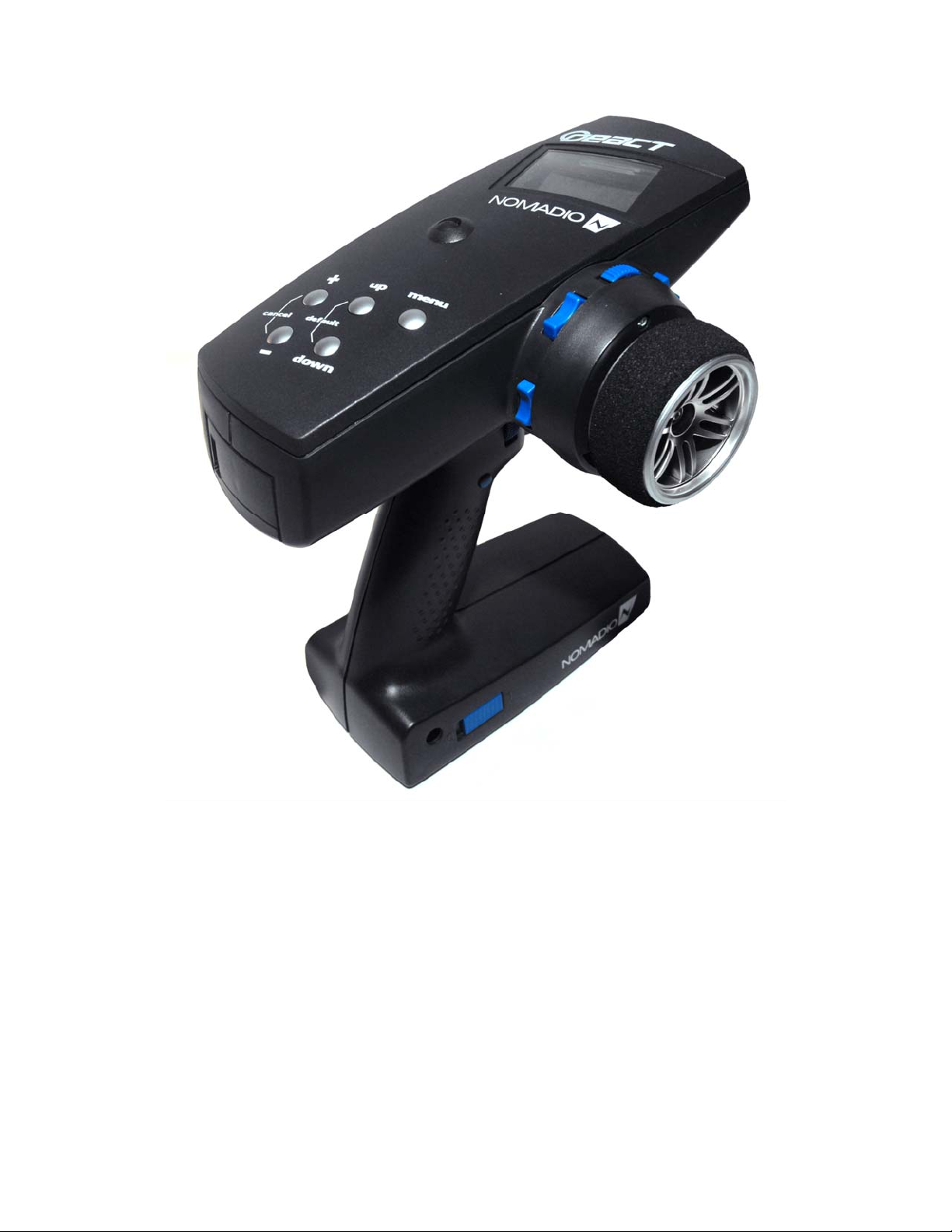
Getting to Know Your React
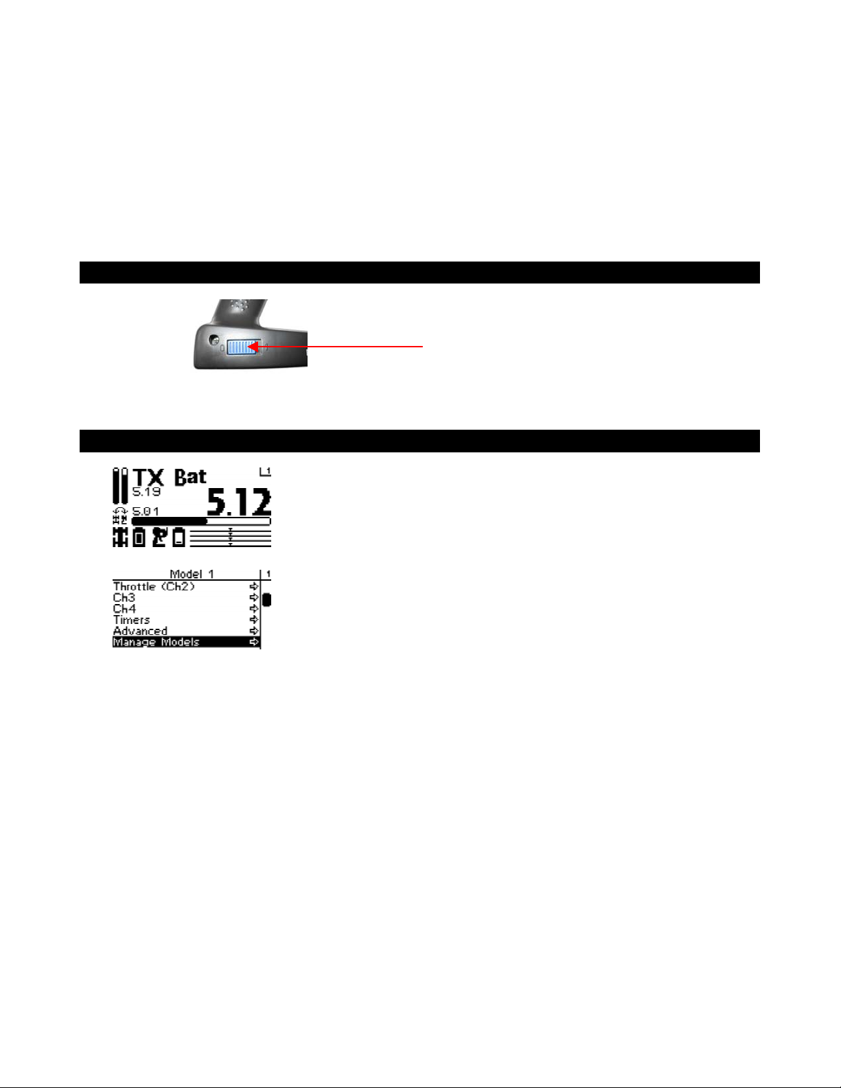
Power Switch
This switch turns the React on and off. It is
recessed to prevent accidental switching during
travel or use.
Display Screen
This is the screen you’ll be seeing 95%
of the time while using the React. It
Driving Screen
displays radio and battery status,
telemetry data that you select and your
servo information.
This screen is the gateway to the
React’s menu system, which is
Menu Screen
described in detail later. You can
always go back to the driving screen by
just pressing the menu key.
Page 8
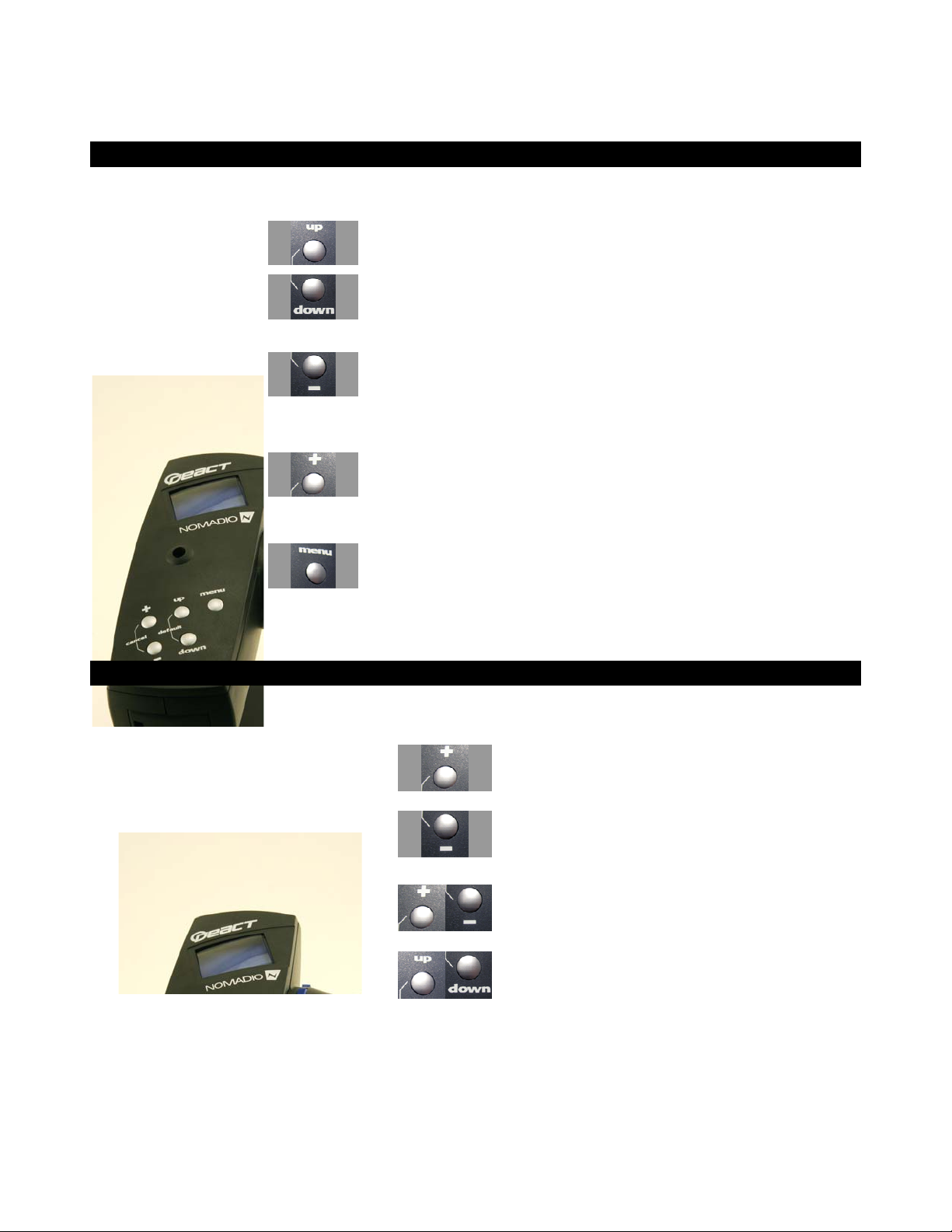
Navigation Buttons
Button In the drive screen In the function menu
Moves to next higher menu item
Moves to next lower menu item
Displays previous reading Decreases selected value
Selection Buttons
Displays next reading
Button In the function menu
Sets the currently edited value to its maximum
value
Sets the currently edited value to its minimum
value
Cancels any changes made and resets value to
where it was before editing started
• Increases selected value
• Goes to next submenu
• Goes to selected submenu
• Saves the change to the selected
setting
Resets the value to its factory default
Page 9
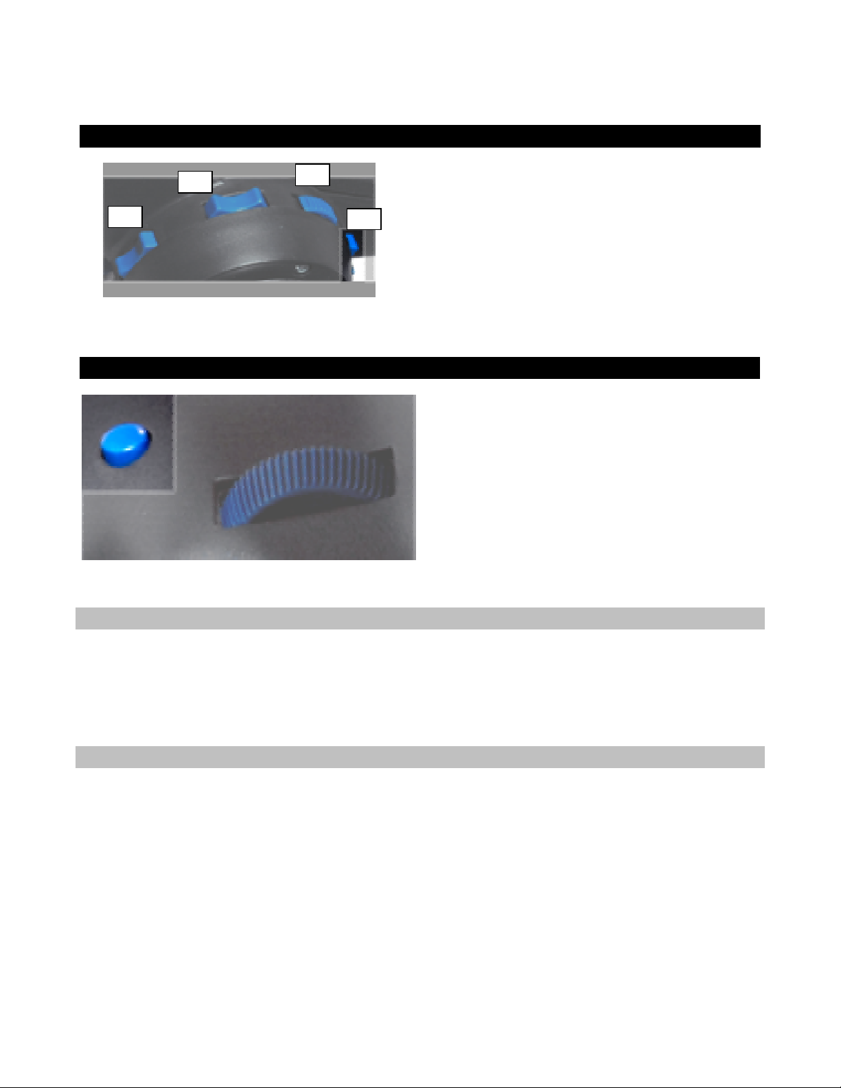
Trim Buttons
Grip Buttons
T3
Button In the drive screen
T1
T2
T3
T4
Perfor ms shifting action on channel 3
Adjusts the steering trim
Adjusts the steering dual rate setting
Adjusts the throttle dual rate setting
Adjusts the throttle trim
Charging and Installing Batteries
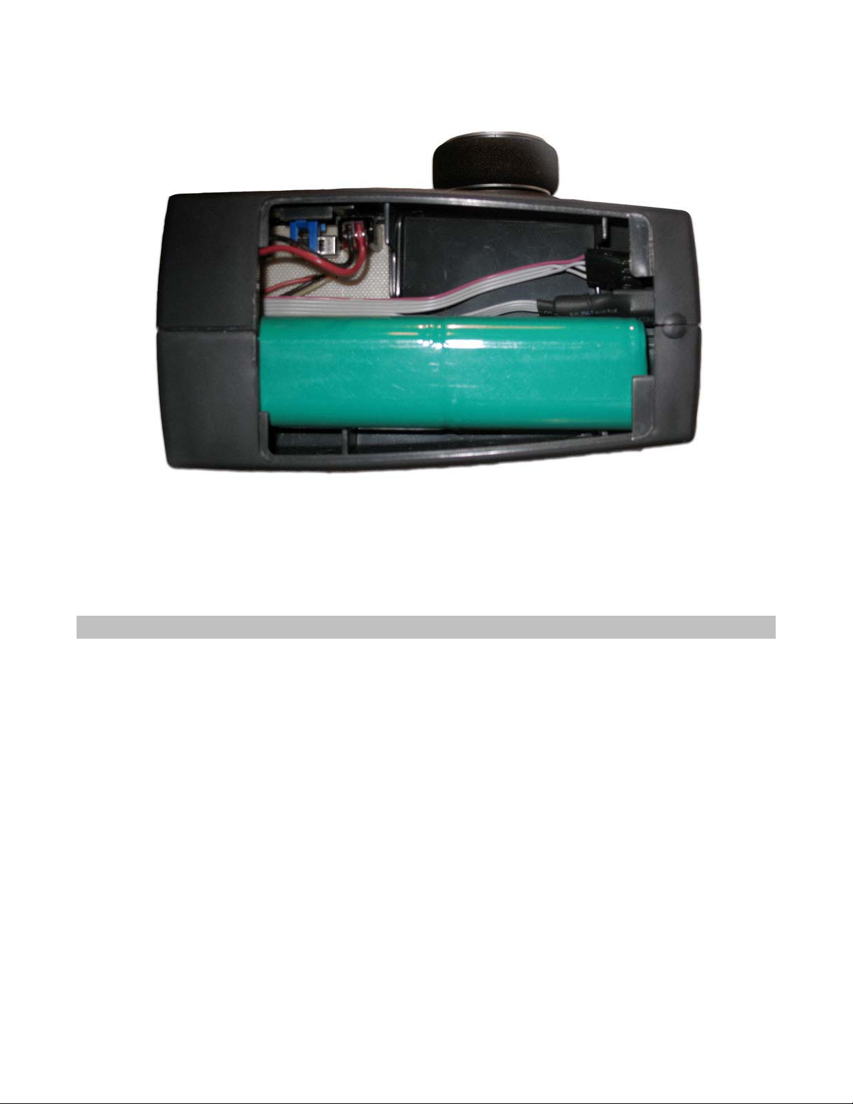
The React is powered by a 4 cell battery pack(included).
Also inside the battery compartment is the 4 wire Receiver Programming Cable. This cable can be
plugged into the receiver’s TACH pins in order to upgrade the software on the receiver. The RC
Desktop will instruct you when a software upgrade is available.
Installing the Batteries
1. Plug the battery connector into the receptacle in the battery compartment. Refer to
photo for battery installation.
Warning!!!! Plugging the battery in backwards will damage the React!!!!!!!!
2. Place the battery holder in the battery compartment. Make sure the wires do not
pinch.
3. Slide the battery compartment cover into place.
Page 10
Charging the Batteries
Make sure the Nomadio React battery pack is properly installed and the React is switched
off. Batteries other than the Nomadio React battery pack cannot be charged by the
React, and attempting to do so will void the warranty. Batteries other than the Nomadio
React battery pack must be removed prior to connecting over USB for any reason, even
when just using RC Desktop.
Connect the USB cables and insert the USB cable into a PC or powered USB hub.
The React will sense a low battery, and will begin charging automatically. To manually
begin charging a battery, hit the “+” key.
The LCD status will display “Charging”, and the timer at the bottom of the screen will
begin. Charging a fully depleted battery should take between 4 and 6 hours.
When the React senses that a battery is fully charged, the LCD status will display “Charge
Done” and will stop charging.
It is safe to manually stop the charging process, by hitting the “-“ key.
If charging fails for any reason, the LCD status will display “Charge Fault”. If this occurs,
verify that:
You are using the Nomadio React battery pack.
Page 11
The battery pack is properly installed.
The USB cables are connected properly.
Installing the Transceiver
Mounting the Transceiver
• Install the transceiver so it is protected from vibration or shock.
• Use double-sided tape or Velcro® to mount the transceiver.
• Position the transceiver where it will not contact other solid components.
• Mount the transceiver away from moving parts, sharp corners, and possible contaminants (fuel,
dirt, etc.).
• When possible, waterproof and protect the transceiver by wrapping it in foam rubber and
placing it in a rubber balloon or plastic bag. If you accidentally get moisture or fuel inside the
transceiver, intermittent or erratic operation may result.
• Position the transceiver so the sensors can be easily connected to it.
Antenna
• The thinner portion at the end of the antenna wire must be outside the vehicle body
• DO NOT CUT the antenna wire
Connecting the Transceiver
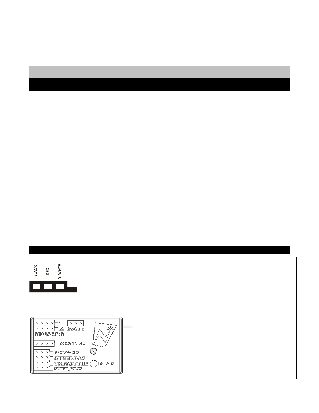
Servo Input Plugs
The transceiver is designed to use Futaba J-style input plugs
with wiring order as shown in the diagram.
Servo lead wires MUST be in this order. If the servo wires
are in a different order, you must re-order the wires in the
input plug. Check with your servo manufacturer about the
color and order of the servo lead wiring.
When you insert the servo input plug into the transceiver,
note that the input plug may have an alignment tab. Orient
the alignment tab properly before inserting the input plug.
To remove in input plug from the transceiver, pull the input
Page 12
plug rather than the servo wires.
Servo Connection
Connect the servos to the appropriate positions in the transceiver:
Connect… …into transceiver receptacle
Receiver battery / Channel 4 servo “Power”
Steering servo “Steering”
Throttle servo or ESC “Throttle”
Shifting servo “Shft/CH3”
FCC Compliance Reminder
If you install the React transceiver inside of a vehicle, and you are not the final end user, FCC
regulations require you to make the React Transceiver’s FCC ID easily visible to the end user. See the
FCC Co mpliance section for more informat ion:
Installing the Optional Sensors
Your React radio system has several optional sensors that you can install in your vehicle and connect to
the transceiver. When properly installed and connected, these sensors will send information back to the
React so that you can monitor the readings while you drive.
Receiver Battery Sensor
The transceiver monitors the receiver battery voltage from the POWER receptacle. There is no
installat ion necessary for this sensor.
Voltage Sensor
The voltage sensor is used to monitor the voltage of a separate battery pack (for example, an electric
car’s main battery pack). In a Nitro car, this sensor is not needed.
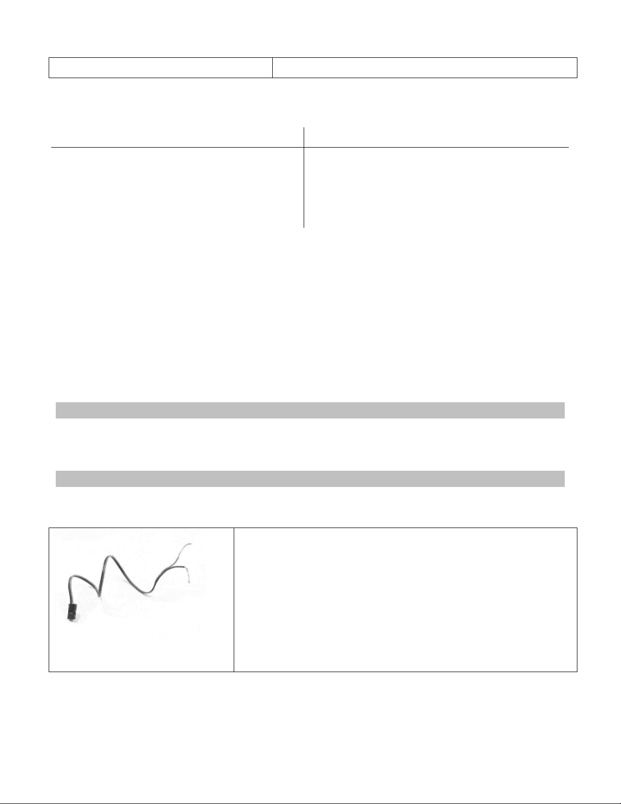
Connecting the Voltage Sensor
1. Connect the RED wire of the voltage sensor to the positive
terminal and the BLACK wire of the voltage sense to the negative
terminal of the battery pack you want to monitor.
2. Carefully route, protect, and secure the sensor wires.
3. Plug the voltage sensor into the BATT receptacle. If your voltage
sensor only has two wires, connect the RED wire to the center pin
and the black wire to either outside pin.
Page 13
Temperature Sensor
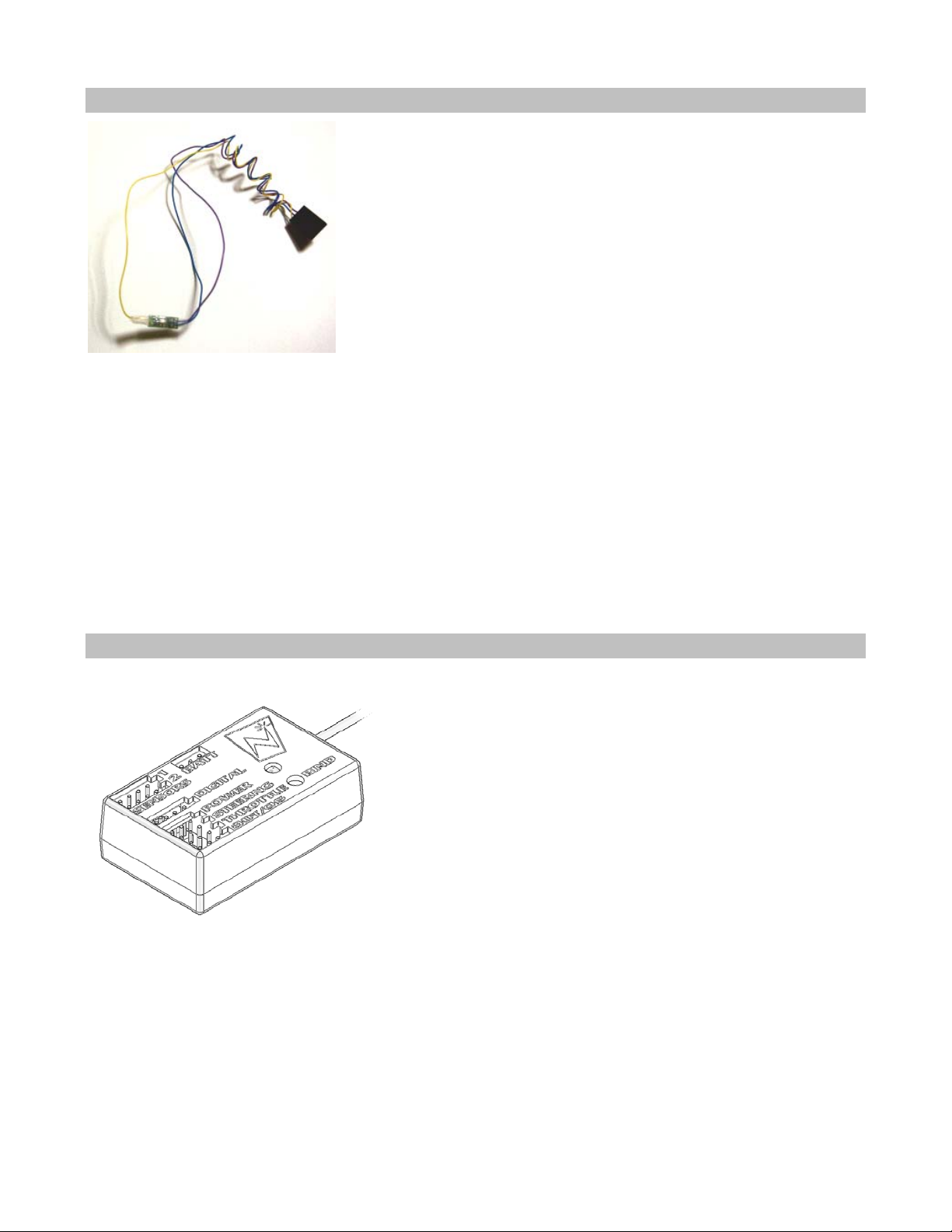
The temperature sensor is used to monitor the temperature of a vehicle
component such as a main battery pack, electric motor, or nitro engine.
Installation
The green circuit board of the sensor is the active measuring element. Install the sensor so that this
board is pressed against the item whose temperature you wish to measure.
The sensor has been designed to be thin enough to fit between the fins on a heat sink. The mounting
wires are strong enough to be used to hold the sensor in place by wrapping them around a cylinder head
or ESC heat sink. Alternately, a high-temperature epoxy may be used to secure the sensor.
When installing on a nitro motor, place the sensor as low as possible on the head, opposite the exhaust
port. The sensor may also be installed on an electric motor, battery pack, or ESC heat sink.
Connection
After you install the temperature sensor in the vehicle, plug it into the “Sensor 1” or “Sensor 2”
receptacle.
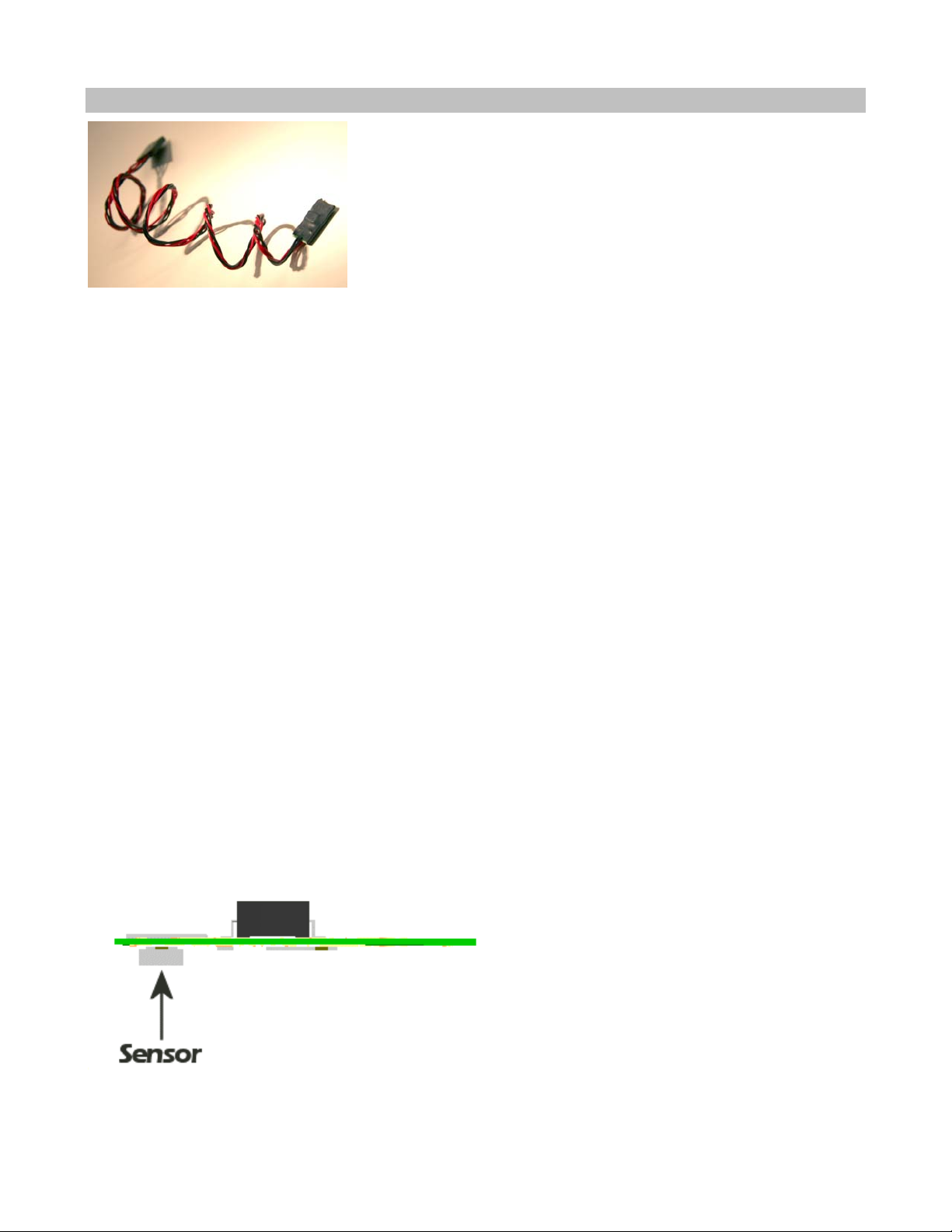
The four-pin connector on the sensor cable has only three wires populated. The unpopulated pin
should be the one furthest from the connector key in the receiver plastic.
The React transceiver will automatically detect which sensors are installed.
Page 14
Tachometer Sensor
The tachometer (“tach”) sensor is used to monitor the rotation speed of a vehicle component such as a
drive shaft and this speed is converted into vehicle speed.
You will need to measure the distance your model rolls in order to provide the React with enough
information to give you an accurate speed. We recommend that you get a tape measure and measure
several rotations of the wheel to reduce the measurement error.
Installation
1. Choose the mounting location
In the drive train, after any clutch or transmission. We recommend that you do not try to mount the
magnets on your motor for magnetic reasons (electric motors) and balance reasons (nitro motors).
Smaller diameter mounting points are better.
The tach sensor must be able to be mounted within 1-2mm of the magnet surface, so you’ll need a solid
mounting point that can position the sensor in the right place.
The completed installat ion should be rigid enough that proximity is maintained without the magnets
impacting the sensor.
2. Install the magnets
Stick two magnets together, mark the exposed faces, then separate them.
Install the magnets with the marked sides out, exactly 180º apart to preserve rotational balance.
IMPORTANT: For correct operation, the sensor must see alternating north and south magnetic poles.
Ideally, countersink the magnets into the surface.
3. Install the tach sensor
Page 15
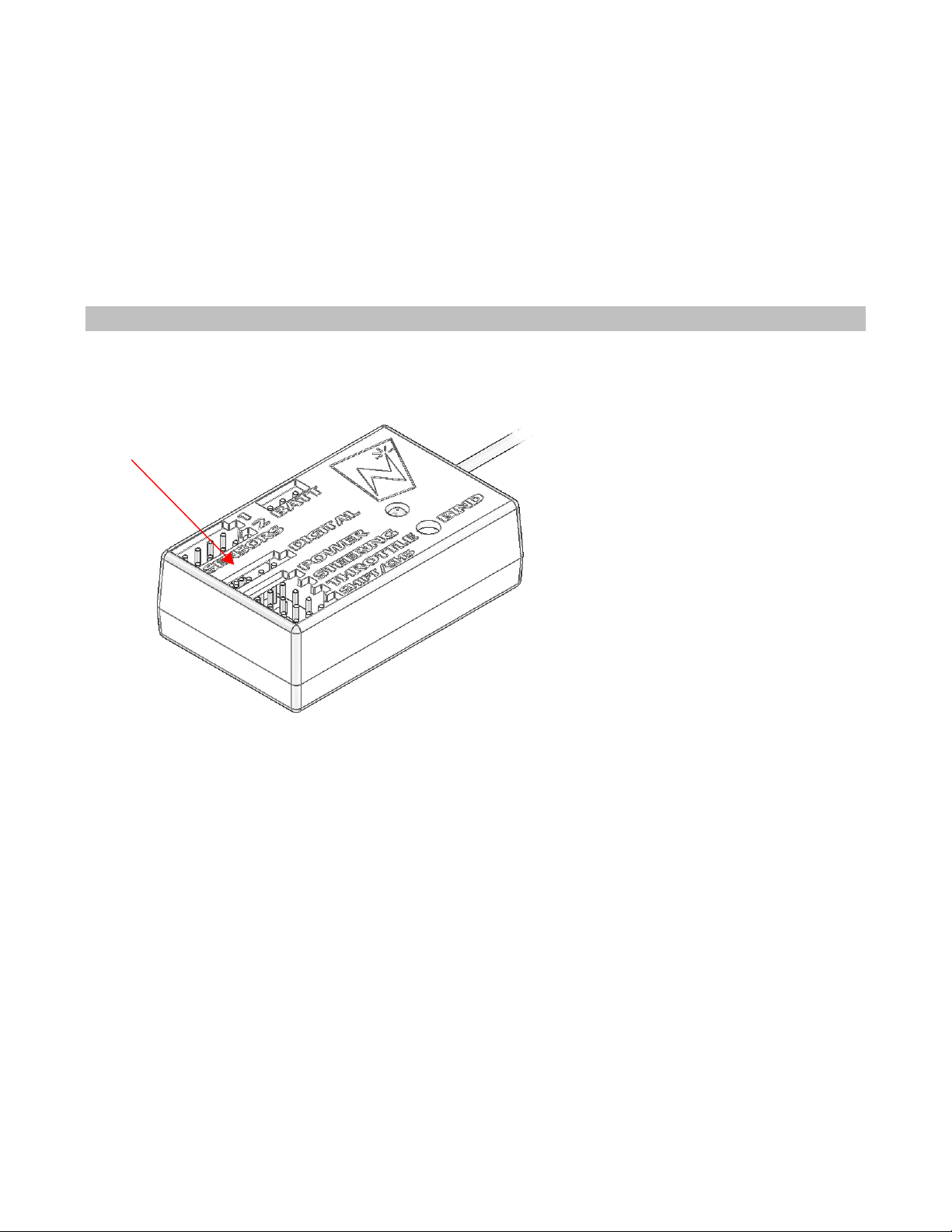
The sensor side of the tach circuit board must be mounted closest to magnets. The sensor is on the
opposite side from the large chip that protrudes from the shrink tubing. The graphic above shows where
the sensor is so you can mount it correctly.
When moving, the magnets should pass directly over the center of the sensor.
We have used a variety of methods of mounting tach sensors, depending on the car and the chosen
location. Some ideas include cable ties, epoxy/hot glue, wire, making a wooden housing that holds the
sensor in a specific place, etc. The only “wrong” way to mount it is if the magnets hit the sensor or are
too far away, or if the sensor moves while the car is running.
Connection
Connect
optional Tach
Connecting the Tach Sensor
After you install the tach sensor in the vehicle, plug it into the “DIGITAL” receptacle.
Plug connector into transceiver – tachometer connector pin 1 (designated with a red wire and an arrow
on the connector body housing) corresponds with the keyed end of transceiver digital port connector
(labelled “digital”). The transceiver will automatically detect which sensors are installed.
Test your sensor’s installation
Power on React and transceiver and bind them
Verify communication between tachometer and transceiver by selecting RPM reading from drive
screen
Correct mechanical installation can be verified by noting RPM value changes on your controller screen
while you spin the wheels of your model.
Page 16

If you don’t see changing RPM values, the magnets or sensor are out of position, or the sensor could be
plugged into the wrong sensor port on your transceiver. If your magnets are hitting the sensor or a part
of your car when the wheels are turning, you must re-mount them so they do not hit anything.
Binding the Transceiver
The binding process “locks” the React and a transceiver together so that they listen only to each other.
Since the React has forty model memories, it is possible that your React will be used to communicate
with as many as forty transceivers. You must therefore perform the binding process once for each
transceiver that will communicate with your React.
Note that the React cannot communicate with all of the transceivers at the same time, but rather the
React will communicate only with the transceiver associated with the React’s currently active model.
For more information, see “Managing Models” later in this instruction manual.
How the Binding Process Works
The binding process is set in motion by depressing the “bind” button on the transceiver when the React
is in “bind mode.” This clears the React ID saved on the transceiver, and allows it to connect to a
React.
When in “bind mode” the React will listen for messages from interested transceivers. When a message
is received the transceiver VIN (the number under the barcode on the FCC label) is displayed, and you
are given the option of connecting to that transceiver or looking for another.
Now, every time you turn on the React and set it to the appropriate model ID (see “Managing Models”
later in this manual), the React sends messages to the appropriate VIN. When you turn on the vehicle’s
transceiver, the transceiver looks for messages from the bound React only.
Binding your transceiver the first time
1. Install a transceiver into your vehicle. (For this example, install a transceiver into your electric
touring car, which will be known to the React as “Model 1.”)
2. In the React’s “Manage Models” function menu, go to “Active Model” and select the appropriate
model ID for the vehicle you are going to bind to. (For this example, select “Model 1.”)
3. After putting your model on a stand to prevent runaways, power up the vehicle and transceiver.
4. In the React’s “Manage Models” function menu, select “Rebind.”
5. Depress and hold the transceiver’s “bind” button until the onboard LED illuminates (you can use an
extended paperclip, ball point pen, small screwdriver, etc).
6: Confirm binding on your React by pressing the “OK” button as the transceiver VIN number is
displayed.
The binding process is now complete.
React Controls
The functions of the React are controlled through the function menu and/or trim controls.
To perform this action... Press......
Page 17
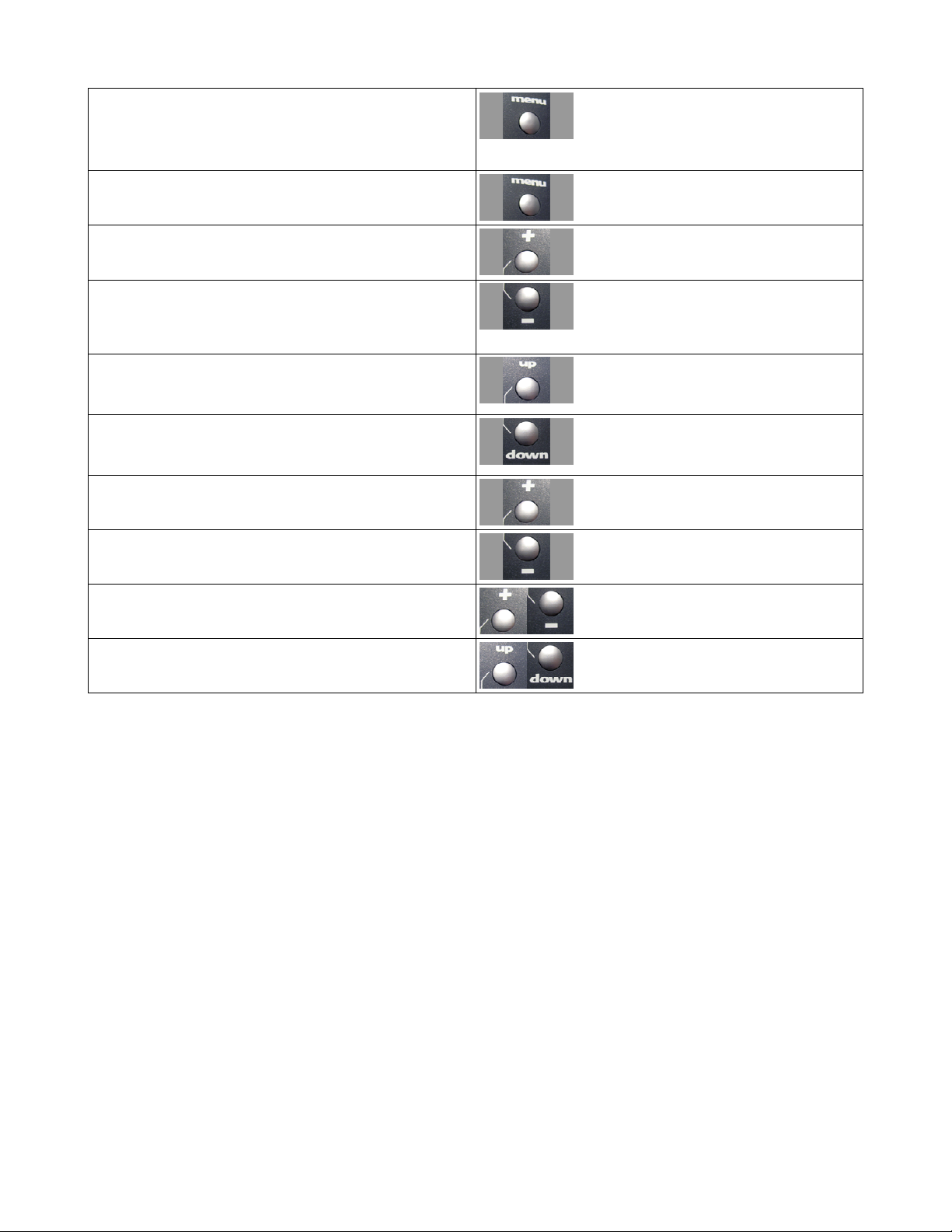
Toggles between the driving screen and the
function menu or returns to the previous level
from a sub-menu
Menu: Go to the selected sub-menu
Menu: Move to the next higher menu item.
Menu: Move to the next lower menu item.
Menu: Go to the selected sub-menu.
Drive: Display next statistic.
Menu: Decrease the selected value setting.
Drive: Display previous statistic.
Menu: Set currently edited value to maximum.
Menu: Set currently edited value to minimum.
Menu: Cancel changes made to the current
parameter.
Menu: Reset currently edited value to factory
default.
Page 18
Top Menu Level
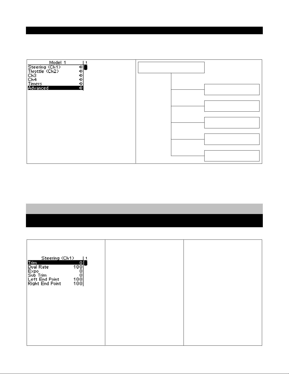
The following illustration shows the function menu structure for the top-level menu. All main submenus may be accessed from the top menu level. Channels 3 & 4 have identical setups, and are
documented together.
Manage Models
Steering Functions
Steering Trim
Active Model
New Model
Delete Model
Copy Model
Rebind
Steering trim adjusts the center
point of the steering servo by
adjusting the center point within
the steering servo’s total travel
range. Unlike steering sub-trim,
the steering left and right end
points are unaffected by steering
trim; by moving the center point
of the steering servo using trim,
the center position moves closer
to one end point or the other.
Steering trim should be used
only after you have initially
adjusted steering sub-trim.
Page 19
4
m
Steering Tri
Steering (Ch1)
Throttle (Ch2)
Shift (Ch3)
Ch
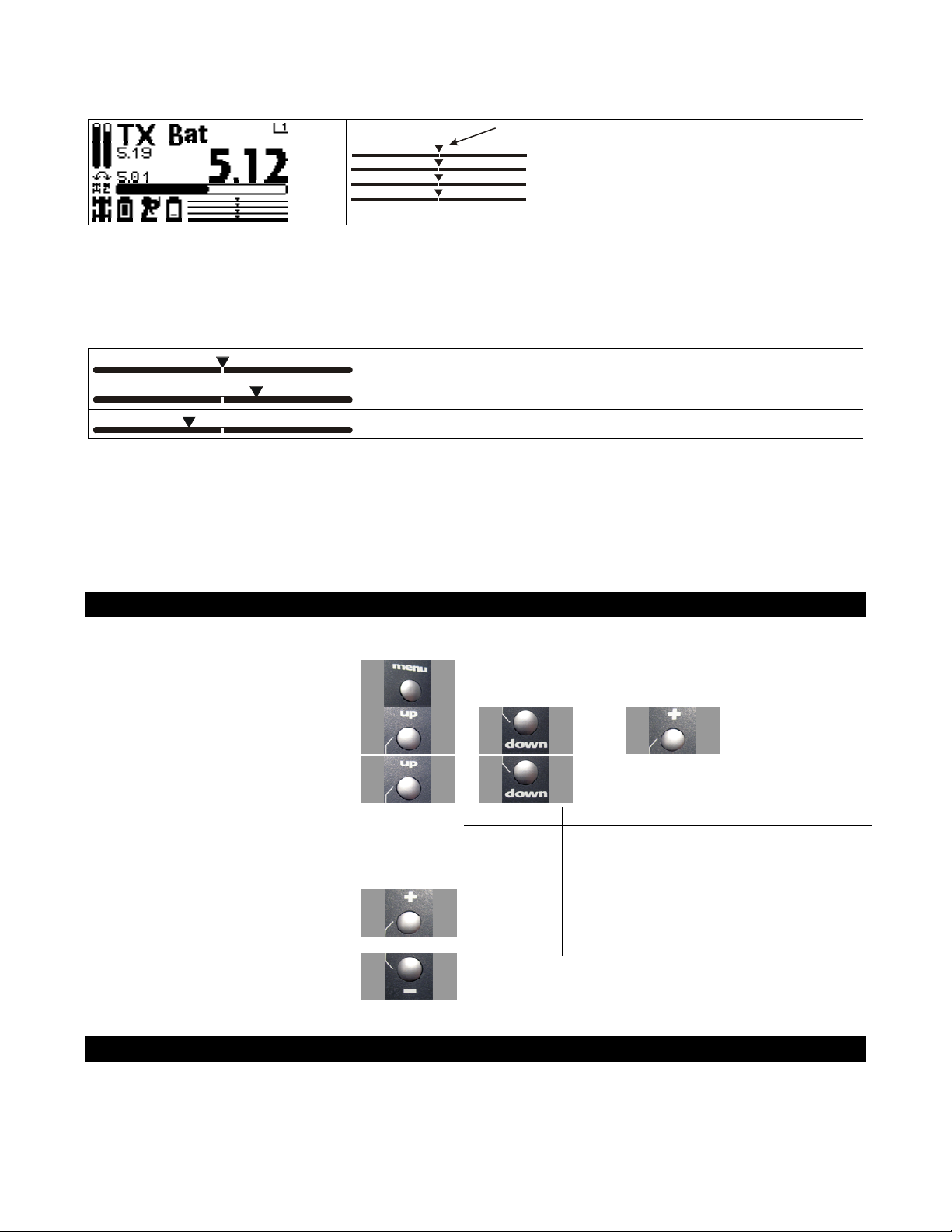
On the driving screen, steering
trim is represented by the
position of the pointer on the
upper bar.
As you change the steering trim, it is shown graphically on the driving screen trim indicator bars:
Steering trim is centered in range (value = 0)
Steering trim is offset to the RIGHT (+ve value
Steering trim is offset to the LEFT (-ve value)
If you find that you have to use a large amount of steering trim to get the vehicle to drive straight, you
should consider resetting the steering trim to 0 and re-adjusting the servo horn on the servo output
shaft.
Adjusting Steering Trim using the Function Menu
Use the navigation controls to adjust steering trim as follows:
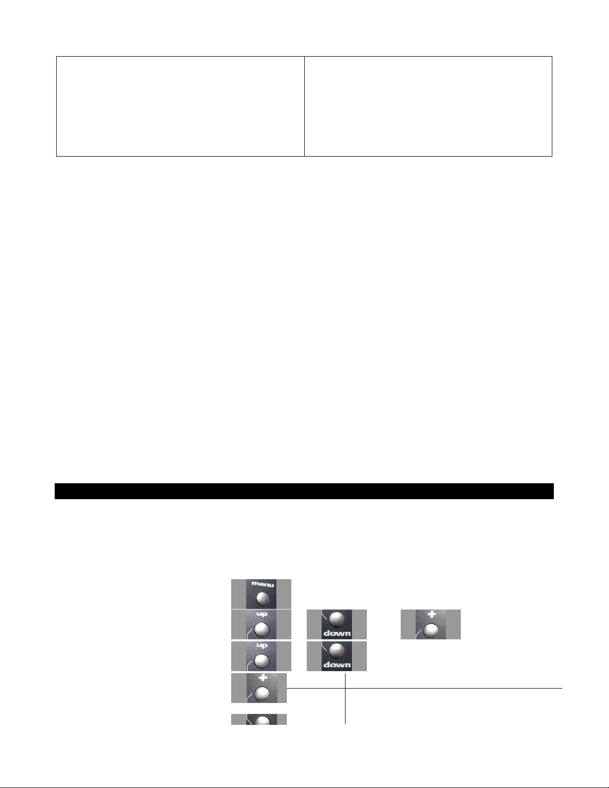
1. Access the top function menu from
the driving screen.
2. Navigate to the Steering (Ch1) menu.
3. Navigate to Trim.
4. Change the value.
or then
or
Value Description
0 Steering trim is centered within the servo
range.
-ve value
(-100 Æ -1)
Steering trim is to the LEFT.
or
+ve value
(1 Æ 100)
Steering trim is to the RIGHT.
Adjusting Steering Trim using the Steering Trim Buttons
Push the trim button forward to advance the trim, backward to reduce it.
A trim (or sub-trim) setting of 100 is equivalent to an End point setting of 50.
Page 20
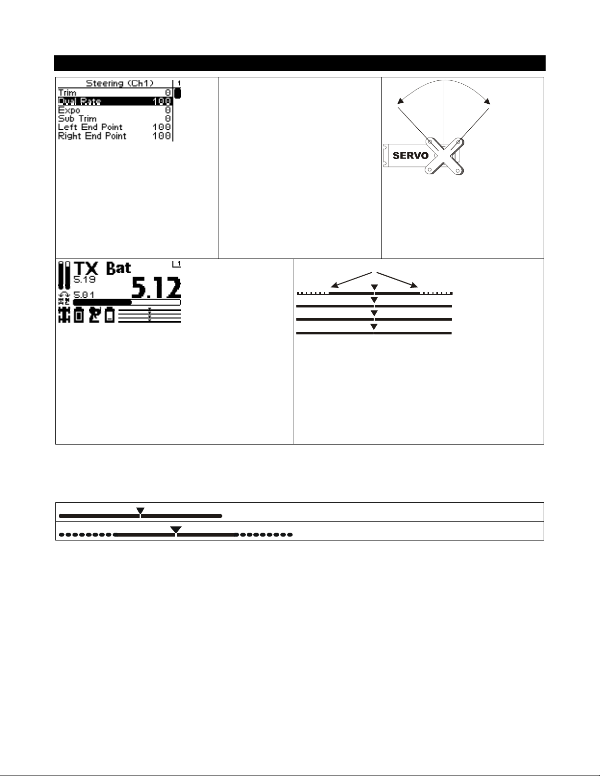
Steering Dual Rate
Steering dual rate adjusts the
range of servo movement when
the steering wheel is fully turned
in either the left or right
direction. This is used to increase
or decrease the steering
sensitivity across the entire servo
range. The steering dual rate
value is applied to both left and
right sides, and is expressed as a
percentage of servo range
(configured by end point
adjustments).
Dual Rate Range
Steering (Ch1)
Throttle (Ch2)
Shift (Ch3)
Ch4
On the driving screen, steering dual rate range is
represented by the solid length of the upper bar.
The total length of the bar (solid and dotted)
represents the servo range. The length of the solid
bar represents the range set by the dual rate value.
As you change the dual rate setting it is shown graphically on the driving screen trim indicator bars:
Full servo range is used.
Lower dual rate value reduces servo range.
Page 21
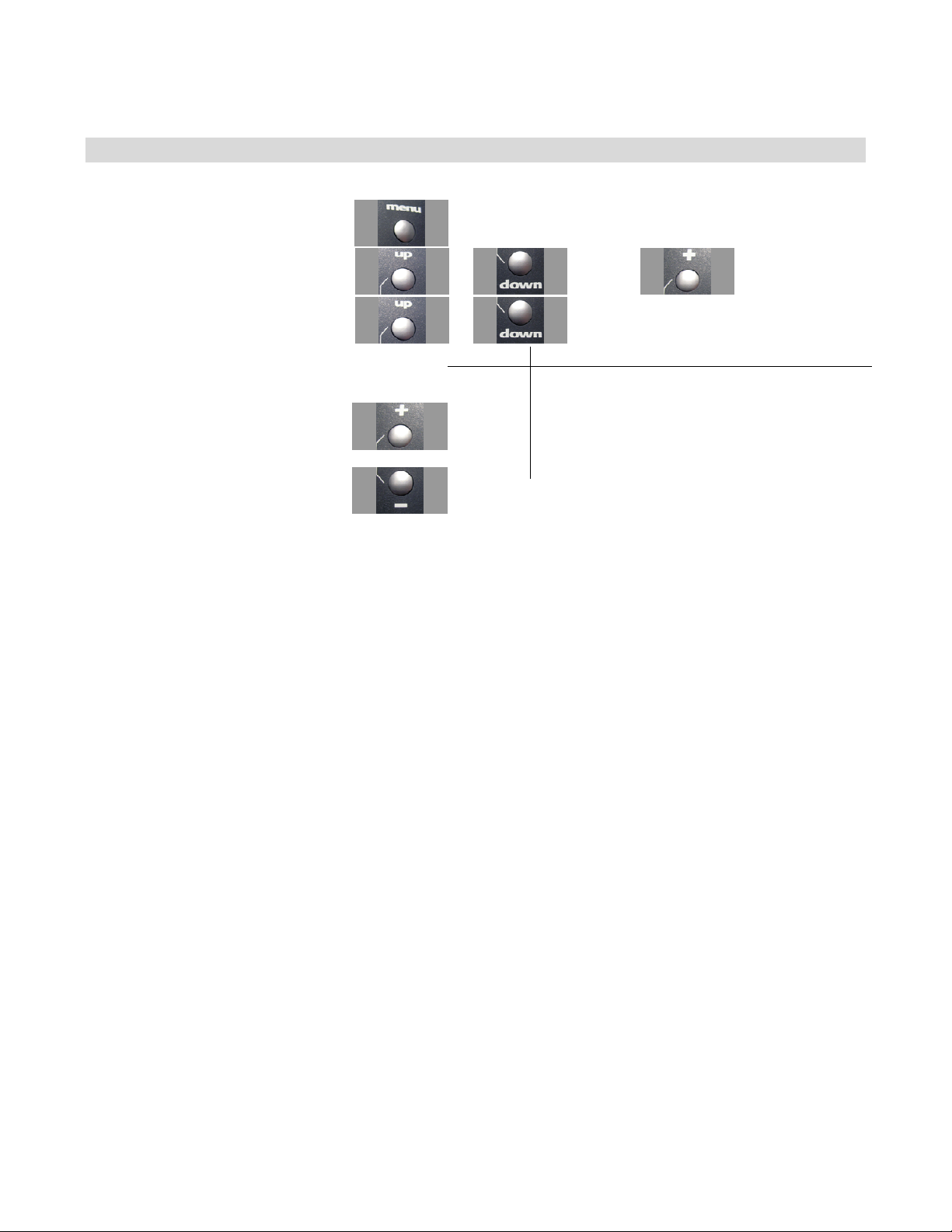
Adjusting Steering Dual Rate using the Function Menu
Use the navigation controls to adjust steering dual rate as follows:
1. Access the top function menu from
the driving screen.
2. Navigate to the Steering (Ch1)
menu.
3. Navigate to Dual Rate.
4. Change the value.
or
or : then
or
Value Description
0 Steering servo range is set to minimum.
Steering servo range is set to a percentage of full
1-99
100 Steering servo range is set to full (100%)
range.
For example, value “50” gives 50% of full servo
range.
Page 22
Adjusting Steering Dual Rate using the Trim Buttons
h
R
You can also use the T2 trim button to adjust the steering dual rate.
Dual Rate and End Point Adjustment
Full servo range is determined by the left and right end point adjustments. The dual rate value
determines the relative servo range between the left and right end points. The servo will never move
beyond the set end point adjustments, no matter what dual rate setting is applied.
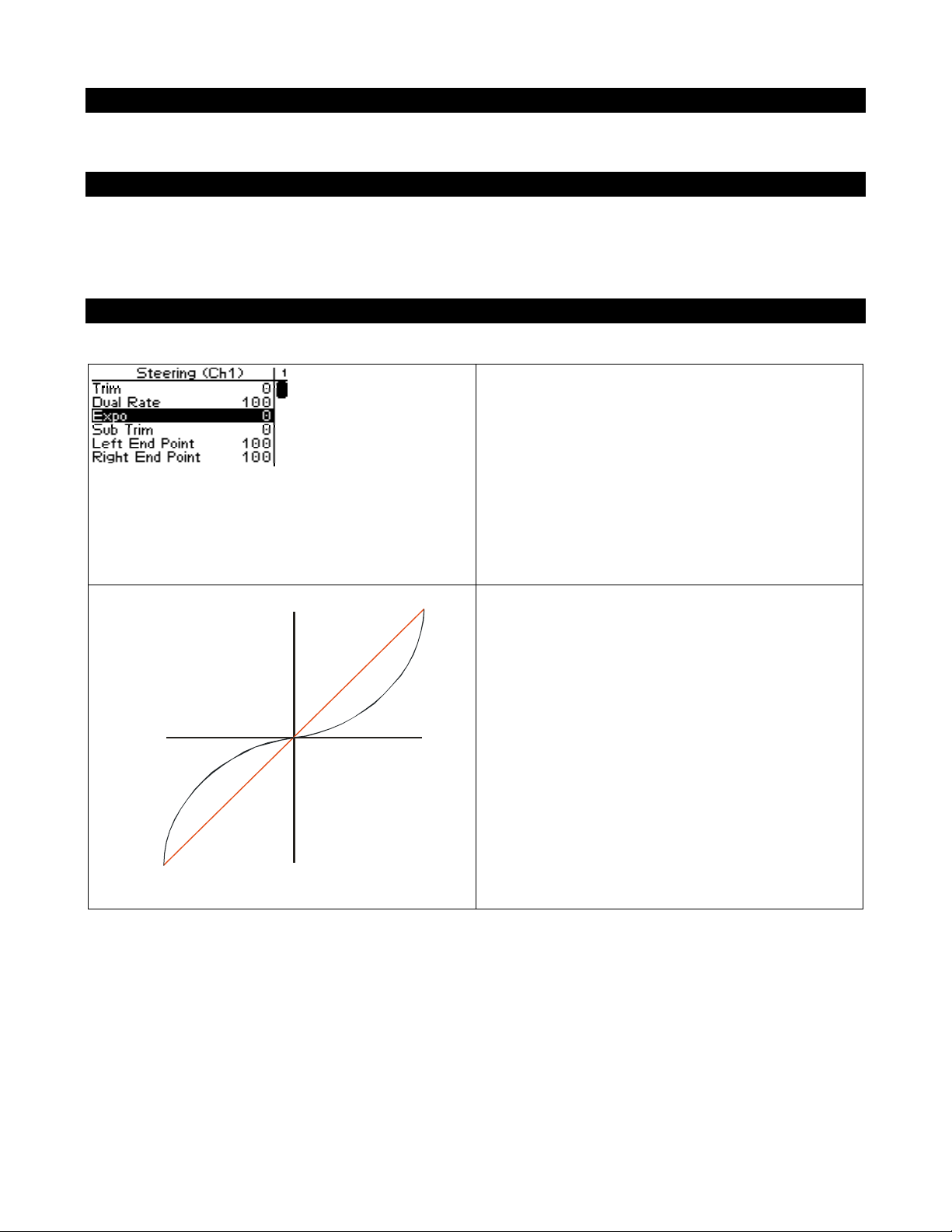
Steering Exponential
Steering exponential adjusts how quickly or
slowly the steering servo responds with respect to
the amount that the steering wheel is turned. This
affects the sensitivity of the steering servo near its
neutral position (center).
Adjusting the steering exponential value affects
both left and right steering response at the same
rate.
-ve exponential
(milder response)
Steering wheel
turned full LEFT
Serv o t ravel
RIGHT
Neutral
Serv o t ravel
LEFT
0% (linear)
-1 ~ -100%
(mild)
Steering w
tur ned full
A negative (-ve) exponential value gives a milder
steering response near the steering neutral point,
making it LESS responsive to small steering
inputs, without affecting total travel like Dual
Rate would.
Page 23
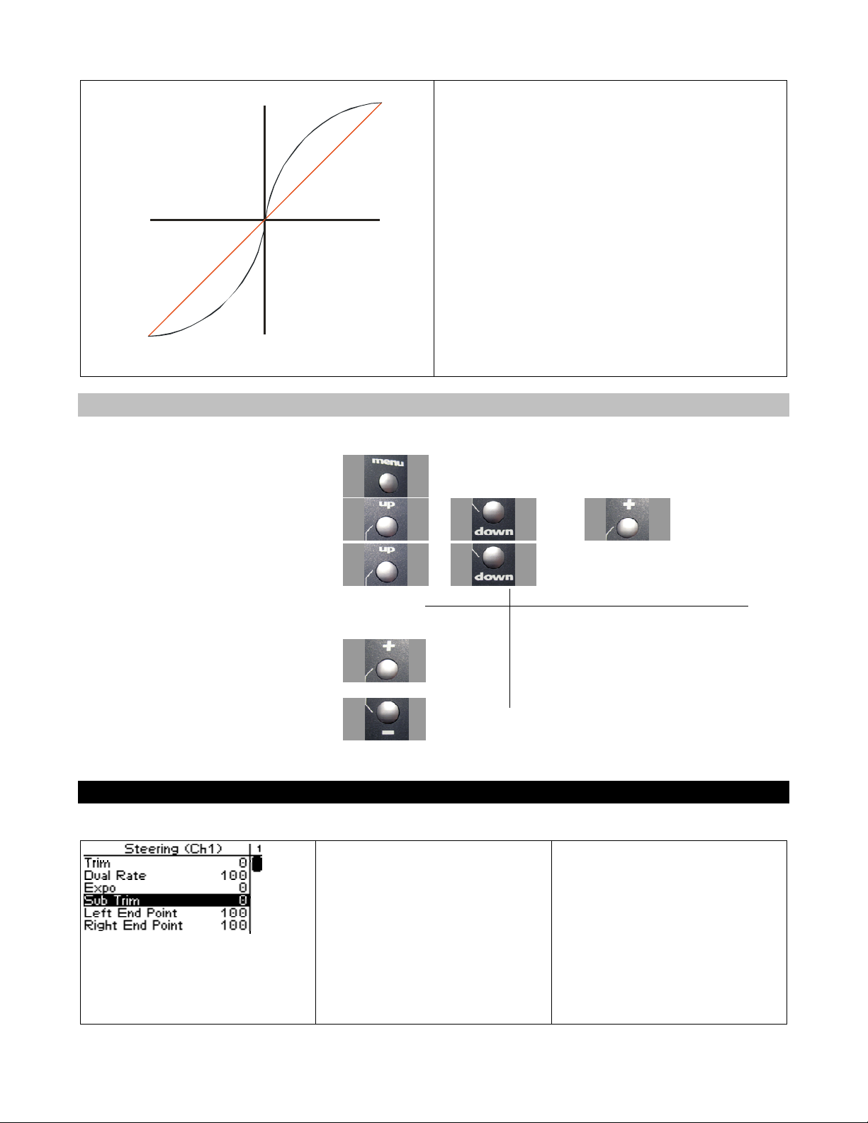
+ve exponential
e
G
(quicker response)
Servo t ravel
RIGHT
1~100%
(quick)
0% (li near)
A positive (+ve) exponential value gives a quicker
steering response near the steering neutral point,
making it MORE responsive to small steering
inputs, without affecting total travel like Dual
Rate would.
Steering wheel
turned ful l LEFT
Neutral
Servo t ravel
LEFT
Stee ring wh
turned full RI
Adjusting Steering Exponential
Use the navigation controls to adjust steering exponential as follows:
1. Access the top function menu from the
driving screen.
2. Navigate to the Steering (Ch1) menu.
3. Navigate to Expo.
or then
or
Value Description
0 Neutral steering response (linear).
4. Change the value.
Steering Sub-Trim
-ve value
(-1 to -100)
or
+ve value
(1 to 100)
Steering sub-trim adjusts the
Milder steering response near center.
Quicker steering response near center.
center point of the steering servo.
This differs from steering trim in
that steering sub-trim adjusts the
servo’s entire travel range; by
moving the center point of the
servo, the left and right end
points (left, right) stay the same
relative “distance” from the
Page 24
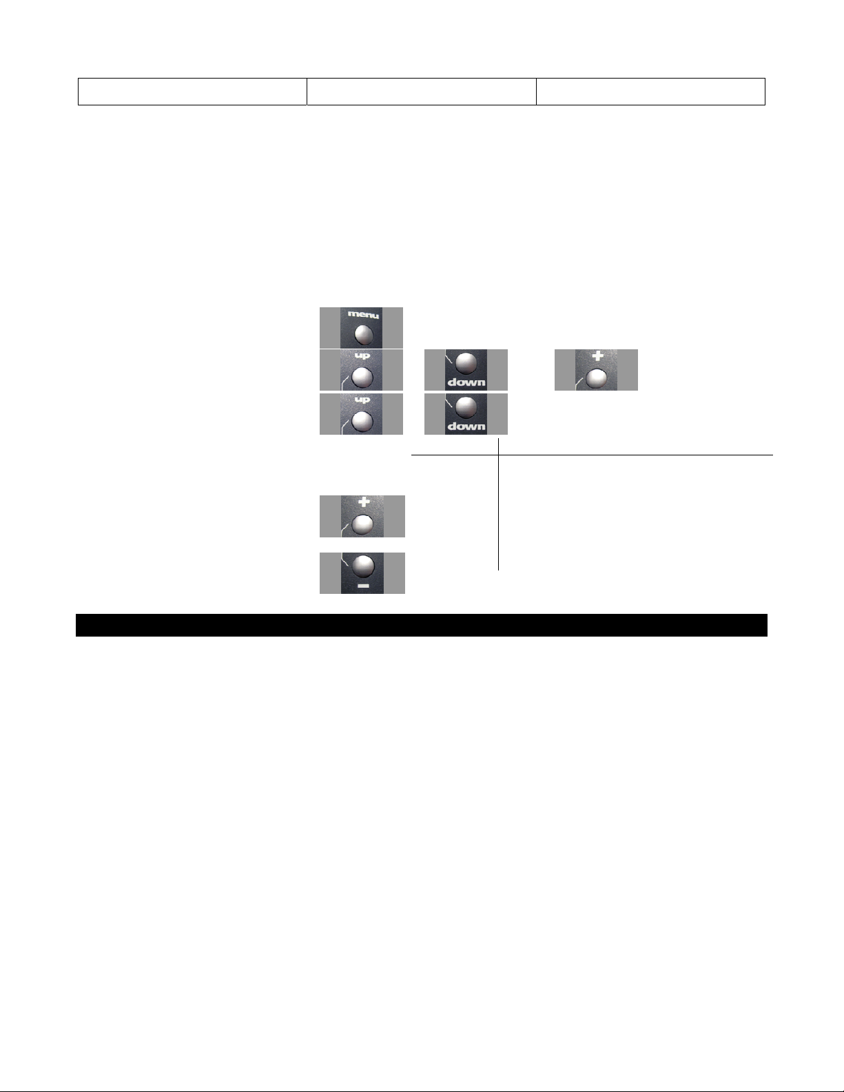
servo center.
Steering sub-trim should be initially adjusted after you have assembled your vehicle’s steering system;
after you begin driving the vehicle, use steering trim to make fine adjustments to center the steering
within the total steering range. If you find that you have to use a large amount of steering sub-trim to
get the vehicle to drive straight, you should consider resetting the steering sub-trim to 0 and readjusting the servo horn on the servo output shaft.
Adjusting Steering Sub-trim
Use the navigation controls to adjust steering sub-trim as follows:
1. Access the top function menu from
the driving screen.
2. Navigate to the Steering (Ch1) menu.
3. Navigate to Sub Trim.
4. Change the value.
or
or then
or
Value Description
0 Steering sub-trim is centered within the servo
range.
-ve value
(-100 Æ -1)
+ve value
(1 Æ 100)
Steering sub-trim is to the LEFT.
Steering sub-trim is to the RIGHT.
Trim and EPA Interaction
Page 25
A trim (or sub-trim) setting of 100 is equivalent to an End point setting of 50.
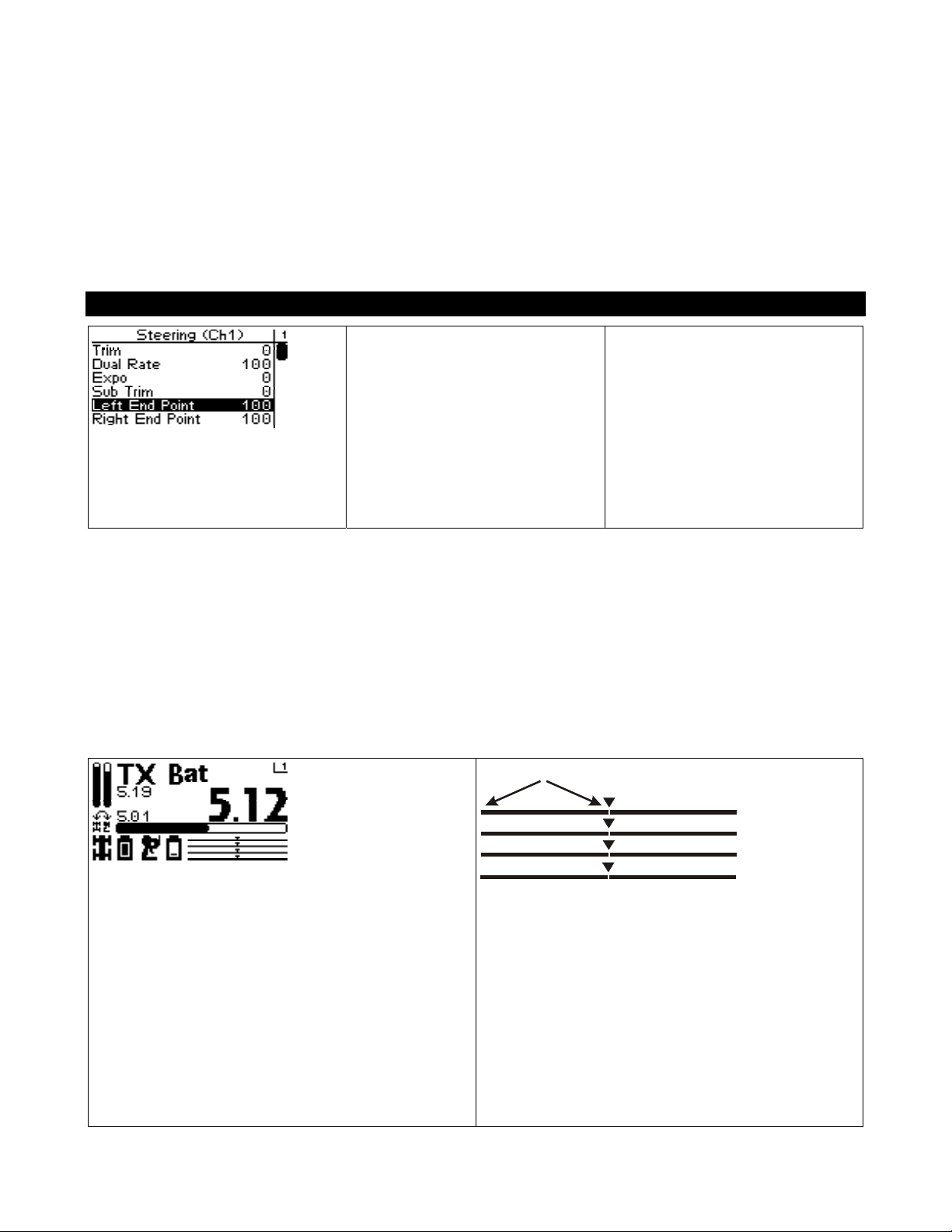
Steering Left End Point
The steering left end point value
adjusts how far the steering
servo turns to the LEFT with
respect to its full range of motion
to the left. End point adjust ment
should be adjusted prior to other
steering settings, as the left end
point value affects other steering
settings.
The left end point is set independently of the right end point (which adjusts how far the steering servo
turns to the RIGHT). The left end point setting should be used to do the following:
Limit steering throw to reduce mechanical binding or servo strain that may occur on full servo throw to
the left. For example, if the servo is trying to turn the steering system to the left farther than it is
mechanically able.
Adjust steering throw to change steering characteristics when turning to the left.
For example, if the current amount of steering throw to the left causes oversteer or understeer when
turning to the left.
Left End Point
Steering (Ch1)
Throttle (Ch2)
Shift (Ch3)
Ch4
On the driving screen, the left end point is
represented by the length of the bar to the left of
the pointer on the upper bar.
The greater the left length of the bar, the greater
the left end point value.
The position of the pointer on the bar is affected
Page 26
by the end point settings (left and right) and trim
settings.
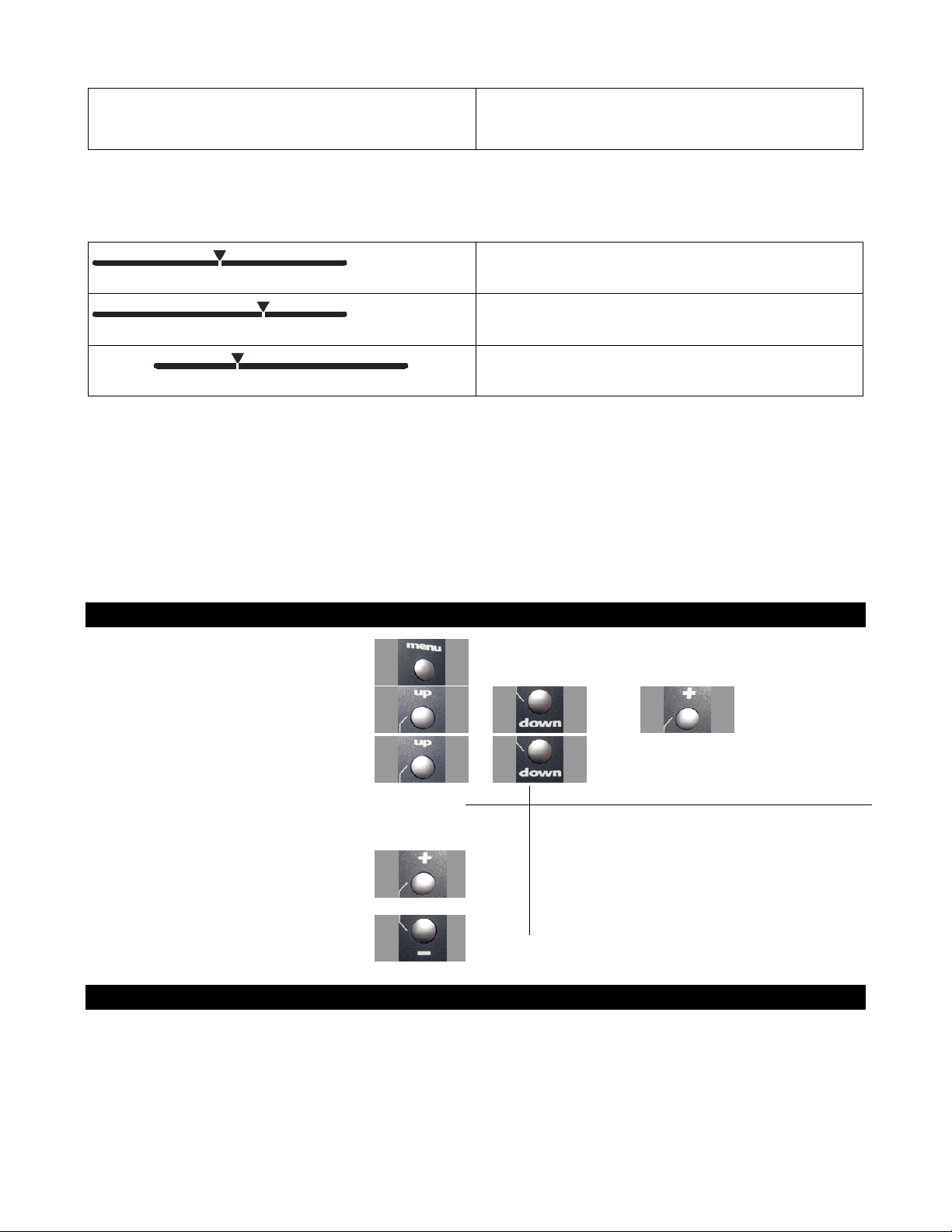
Changing the left end point value has the following visual effect on the driving screen bars.
Left end point value is approximately the same as
the right end point value.
Increased left end point value (more servo travel
to the left is possible).
Decreased left end point value (less servo travel to
the left is possible).
The position of the pointer on the bar is affected by the steering end point settings (left and right) and
trim setting; increasing the left end point value may visually appear to have the same effect as
decreasing the right end point value.
An end point setting of 100 (the default) is typical for most servos, and should always be used for
ESCs. Larger setting values will overdrive most servos.
Use the navigation controls to adjust the left end point as follows:
1. Access the top function menu from the
driving screen.
2. Navigate to the Steering (Ch1) menu.
or then
3. Navigate to Left End Point.
or
Value Description
Minimum left end point; allows NO turning motion
0
to the left.
4. Change the value.
or
1-200
200
Left end point value is set to a percentage of full
left-turning range.
Maximum left end point (will overdrive most
servos)
Trim and EPA Interaction
A trim (or sub-trim) setting of 100 is equivalent to an End point setting of 50.
Page 27
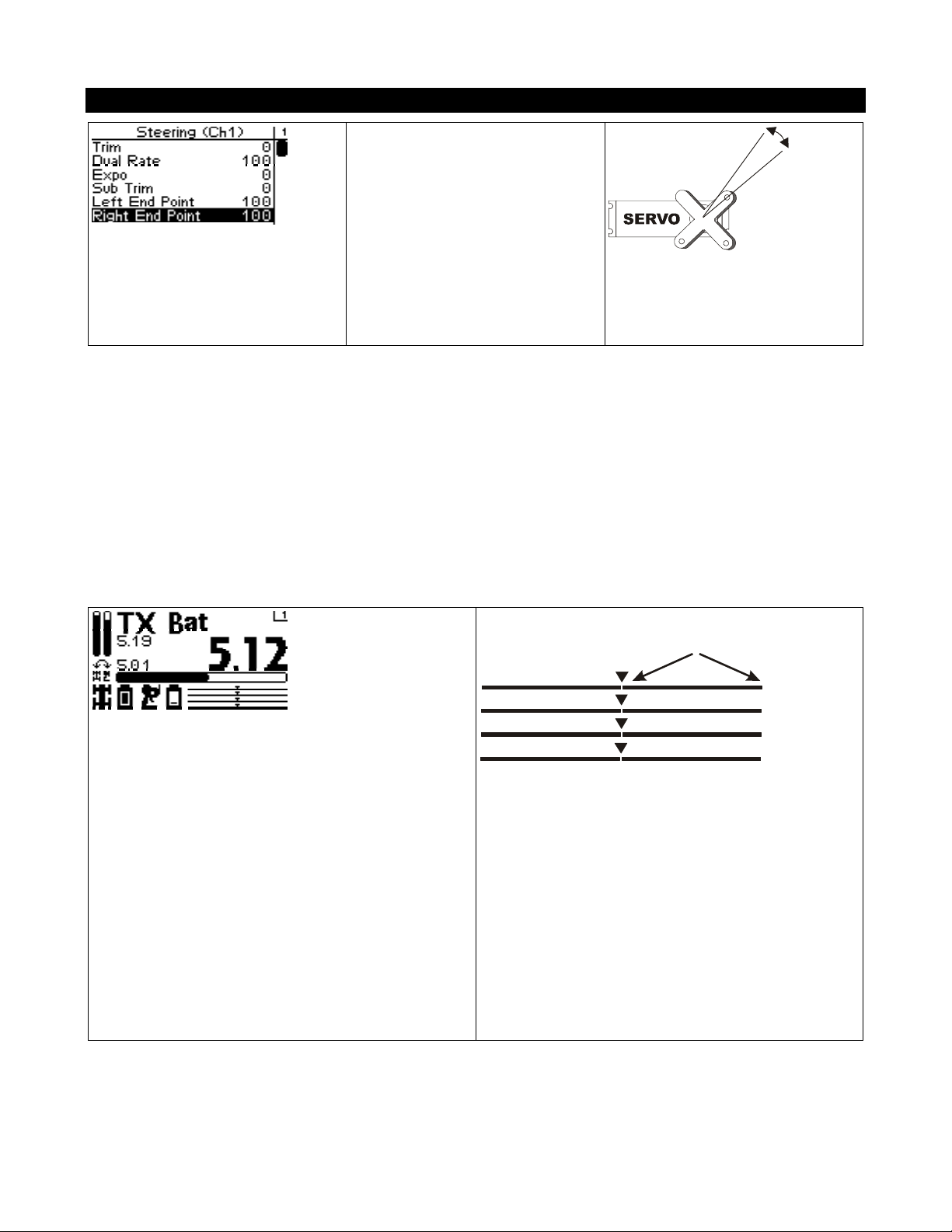
Steering Right End Point
The steering right end point
value adjusts how far the
steering servo turns to the
RIGHT with respect to its full
The right end point is set independently of the left end point (which adjusts how far the steering servo
turns to the LEFT). The right end point setting should be used to do the following:
Limit steering throw to reduce mechanical binding or servo strain that may occur on full servo throw to
the right. For example, if the servo is trying to turn the steering system to the right farther than it is
mechanically able.
Adjust steering throw to change steering characteristics when turning to the right.
For example, if your car is oversteering when turning to the right, then reduce the Right End Point
value to reduce the range of the steering servo on the right.
range of motion to the right. End
point adjustment should be
adjusted prior to other steering
settings, as the right end point
value affects other steering
settings.
Right End Point
Steering (Ch1
Throttle (Ch2)
Shift (Ch3)
Ch4
On the driving screen, the right end point is
represented by the length of the bar to the right of
the pointer on the upper bar.
The greater the right length of the bar, the greater
the right end point value.
The position of the pointer on the bar is affected
by the end point values (left and right) and trim
setting.
Changing the right end point value has the following visual effect on the driving screen bars.
Page 28
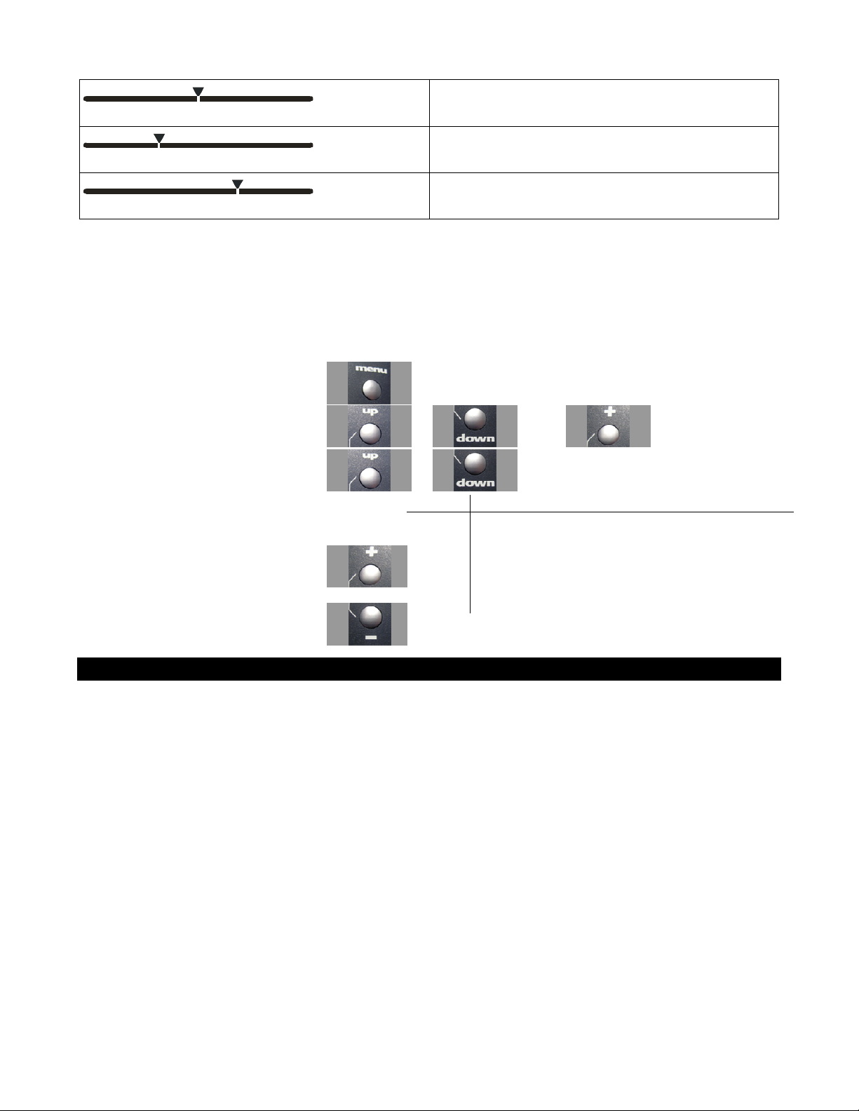
Right end point value is approximately the same
as the left end point value.
Increased right end point value (more servo travel
to right is possible).
Decreased right end point value (less servo travel
to right is possible).
The position of the pointer on the bar is affected by the steering end point values (left and right) and
trim setting; increasing the right end point value may visually appear to have the same effect as
decreasing the left end point value.
An end point setting of 100 (the default) is typical for most servos, and should always be used for
ESCs. Larger setting values will overdrive most servos
Use the navigation controls to adjust the right end point as follows:
1. Access the top function menu from the
driving screen.
2. Navigate to the Steering (Ch1) menu.
3. Navigate to Right End Point.
4. Change the value.
or
or then
or
Value Description
Minimum right end point; allows NO turning motion
0
to the right.
1-200
200 Maximum right end point (will overdrive most servos)
Right end point setting is set to a percentage of full
right-turning range.
Trim and EPA Interaction
A trim (or sub-trim) setting of 100 is equivalent to an End point setting of 50
Page 29
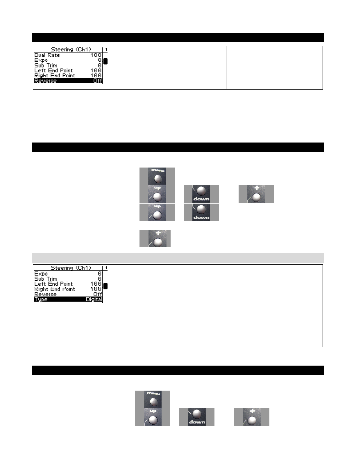
Steering Servo Reverse
Steering Servo Reverse
reverses the direction the
servo moves upon
receiving an input from
the steering wheel.
Changing the Steering Servo Reverse Setting
Use the navigation controls to change the steering servo reverse setting as follows:
1. Access the top function menu from the
driving screen.
2. Navigate to the Steering (Ch1) menu.
3. Navigate to Servo Reverse.
4. Change the value.
or then
or
Value Description
Off Standard servo direction.
On Reversed servo direction.
Steering Servo Type
Steering servo type lets you select the type of
steering servo (analog or digital) in the vehicle.
Analog servos are sent signals at 50 frames/sec,
while Digital servos are sent signals at 100
frames/sec.
If you have high-end analog servos, they may
operate better with the digital setting, try both
settings and choose the best performance.
Changing the Steering Servo Type
Use the navigation controls to change the steering servo type as follows:
1. Access the top function menu from
the driving screen.
2. Navigate to the Steering (Ch1) menu.
or then
Page 30
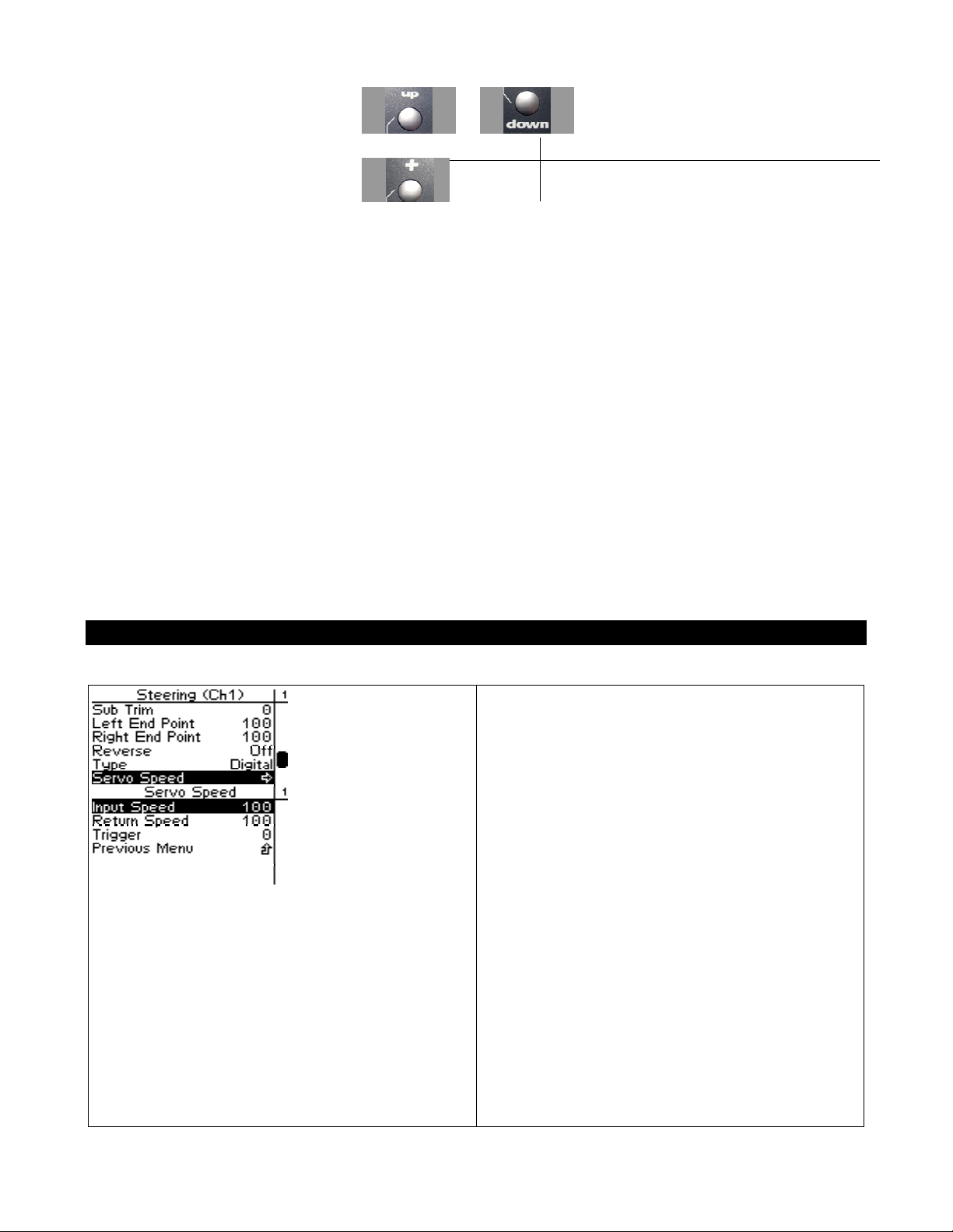
3. Navigate to Servo Type.
4. Change the value.
or
Value Description
Analog Steering servo is analog.
Digital Steering servo is digital.
Steering Speed
Steering speed allows you to limit the maximum
speed that the steering servo will be driven to
match your movements on the wheel. There are
three parameters that can be adjusted to precisely
set up your limiting.
Trigger sets the minimum amount of control input
before the speed limiter becomes active. At 0%,
limiting is always active (input is always >= 0%).
At 50%, limiting is only active if the wheel is
turned half way or more.
Input speed determines the limited speed that is
applied to motions away from center that are
above the trigger setting. 100 is the maximum
servo movement rate. 1 is the minimum rate.
Default is 100 (full speed)
Page 31
Return speed determines the limited speed that is
applied to motions back toward center that are
above the trigger setting. 100 is the maximum
servo movement rate. 1 is the minimum rate.
Default is 100 (full speed)
Changing the Steering Speed
Interaction with other parameters
Servo Speed is applied after Expo. The trigger level for Servo Speed refers to the curved input value.
Use the navigation controls to change the steering servo type as follows:
1. Access the top function menu from
the driving screen.
2. Navigate to the Steering (Ch1) menu.
or then
3. Navigate to Steering Speed.
4. Change the values.
or
or
Value Description
Input
Speed
The percentage of full speed applied to servo
motion away from center once the trigger amount
has been exceeded.
Page 32

Return
Speed
Trigger
The percentage of full speed applied to servo
motion toward center once the trigger amount has
been exceeded.
The threshold above which speed limiting will be
applied.
Page 33
Throttle Functions
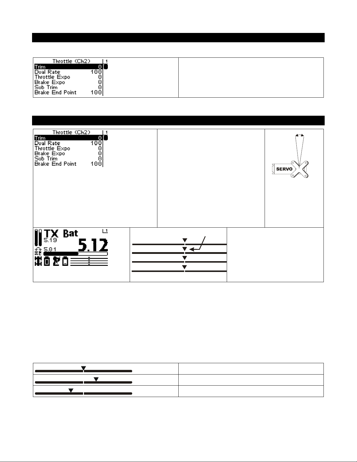
The following illustration shows the function menu structure for the throttle functions:
Throttle Trim
Throttle trim adjusts the resting
(centered) position of the throttle
servo horn (electric or nitro vehicle)
or the neutral point of an ESC
(electric vehicle).
When initially setting up the vehicle,
the throttle trim setting should be set
to 0. On a throttle servo, the servo
horn should be positioned as
appropriate on the servo.
Throttle Trim
Changing the throttle trim has the following visual effect on the driving screen bars:
Throttle trim is centered in range (value = 0)
Throttle trim is offset to throttle end (+ve value)
Throttle trim is offset to brake end (-ve value)
On the driving screen, throttle
trim is represented by the
position of the pointer on the
middle bar.
Page 34
Adjusting Throttle Trim using the Function Menu
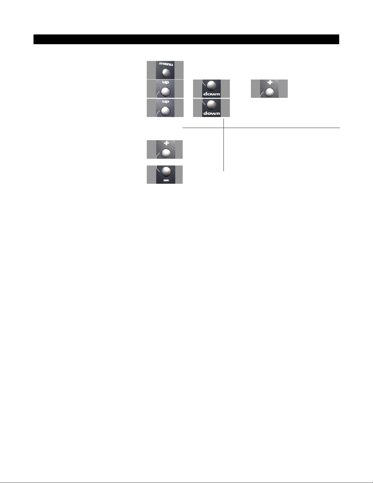
Use the navigation controls to adjust throttle trim as follows:
1. Access the top function menu from the
driving screen.
2. Navigate to the Throttle (Ch2) menu.
3. Navigate to Trim.
or then
or
Value Description
0 Throttle trim is centered within servo range.
4. Change the value.
or
-ve value
(-100 Æ -1)
+ve value
(1 Æ 100)
Throttle trim is to the BRAKE end.
Throttle trim is to the THROTTLE end.
Page 35
Adjusting Throttle Trim using the Trim Button
You can also use the T3 trim button to adjust throttle trim.
Trim and EPA Interaction
A trim (or sub-trim) setting of 100 is equivalent to an End point setting of 50.
Throttle Dual Rate
Throttle dual rate adjusts the
range of servo movement when
the throttle trigger is moved from
full brake to full throttle position.
This is used to increase or
decrease the throttle sensitivity
across the entire servo range.
The throttle dual rate value is
applied to both throttle and brake
end, and is expressed as a
percentage of servo range
(configured by end point
adjustments).
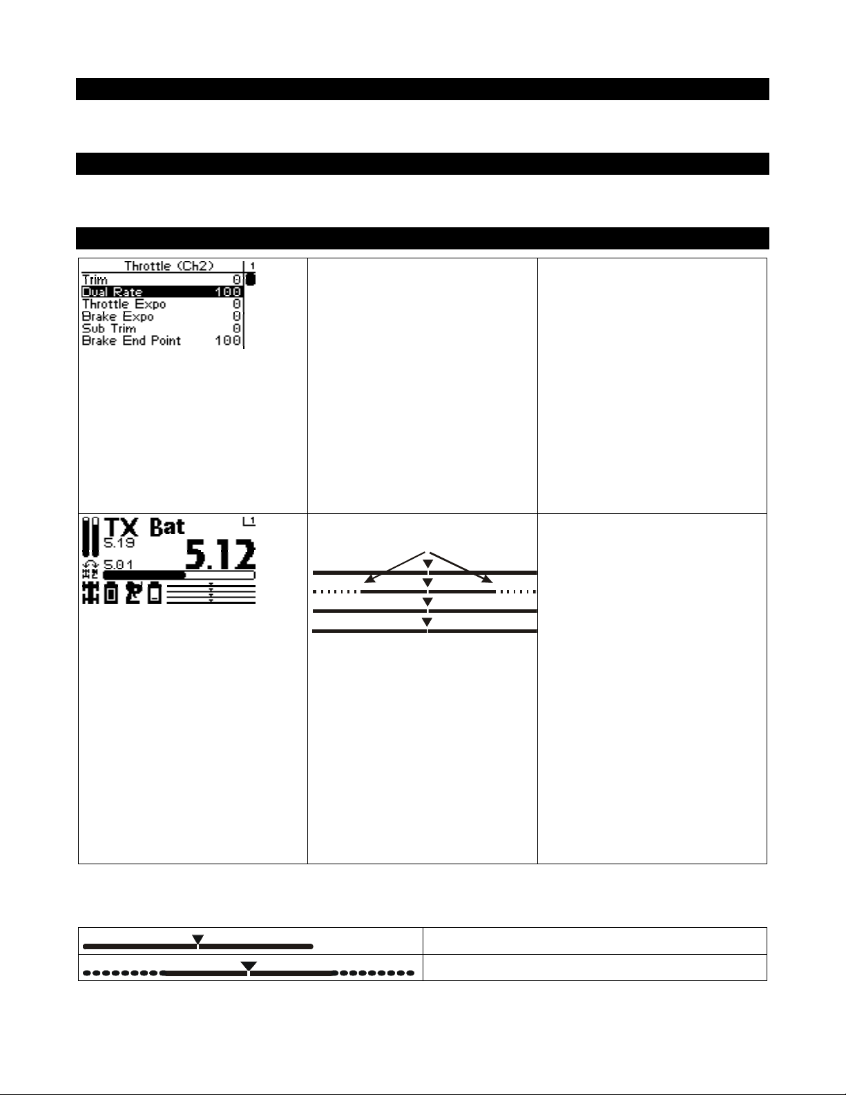
Throttle Dual Rate Range
On the driving screen, throttle
dual rate range is represented by
the solid length of the middle
bar.
The total length of the bar (solid
and dotted) represents the servo
range. The length of the solid bar
represents the servo range set by
the dual rate value.
Changing the dual rate setting has the following visual effect on the driving screen bars:
Full servo range is used.
Lower dual rate value reduces servo range.
Page 36
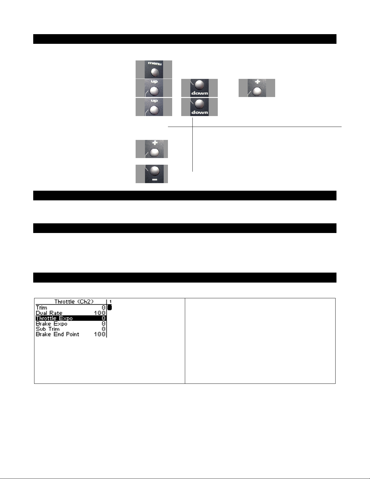
Adjusting Throttle Dual Rate using the Function Menu
Use the navigation controls to adjust throttle dual rate as follows:
1. Access the top function menu from
the driving screen.
2. Navigate to the Throttle (Ch2)
menu.
3. Navigate to Dual Rate.
or then
or
Value Description
1 Throttle/brake range is set to minimum.
4. Change the value.
1-99
or
100 Throttle/brake range is set to full (100%)
Throttle/brake range is set to a percentage of full range.
For example, value “50” gives 50% of full servo range.
Adjusting Throttle Dual Rate using the Trim Button
You can also use the T1 trim button to adjust throttle dual rate.
Dual Rate and End Point Adjustment
Full servo range is determined by the throttle and brake end point adjustments. The dual rate value
determines the relative servo range between the throttle and brake end points. The servo will never
move beyond the set end point adjust ments, no matter what dual rate setting is applied.
Throttle Exponential
Throttle exponential adjusts how quickly or
slowly the throttle servo responds with respect to
the amount that the throttle trigger is moved to the
THROTTLE end. This affects the sensitivity of
the throttle servo near its neutral position.
Adjusting the throttle exponential does not affect
the brake exponential; these settings are set
individually.
Page 37

Servo travel
THROTTLE
0% (linear)
-1 ~ -100%
(mi ld )
A negative (-ve) exponential value gives a milder
throttle response near the throttle neutral point,
making it LESS responsive to small throttle
inputs, without changing overall throttle travel
like Dual Rate would.
Neutral
-ve exponential
(milder response)
Servo travel
THROTTLE
1~100%
(quick)
Neutral
+ve exponential
(quicker response)
0% (l inear )
F ull thr ot tle
A positive (+ve) exponential value gives a quicker
throttle response near the throttle neutral point,
making it MORE responsive to small throttle
inputs, without changing overall throttle travel
like Dual Rate would.
F ull thr ot tle
Page 38
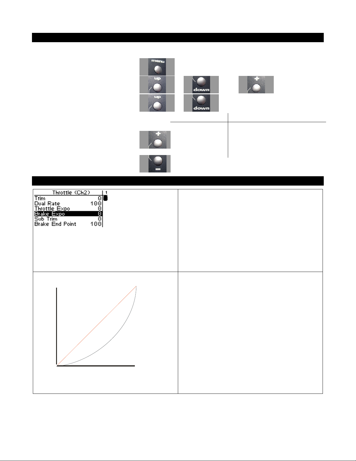
Adjusting Throttle Exponential
Use the navigation controls to adjust throttle exponential as follows:
1. Access the top function menu from the
driving screen.
2. Navigate to the Throttle (Ch2) menu.
3. Navigate to Throttle Expo.
4. Change the value.
or
or then
or
Value Description
0 Neutral throttle response (linear).
-ve value
(-1 to -100)
+ve value
(1 to 100)
Brake Exponential
Brake exponential adjusts how quickly or slowly
the throttle servo responds with respect to the
amount that the throttle trigger is moved to the
BRAKE end. This affects the sensitivity of the
throttle servo near its neutral position.
Milder throttle response near neutral.
Quicker throttle response near neutral.
Servo t rave l
THROTTLE
Neutral
0% (linear)
-ve exponential
(milder response)
Adjusting the brake exponential does not affect
the throttle exponential; these settings are set
individually.
A negative (-ve) exponential value gives a milder
braking response near the throttle neutral point,
making it LESS responsive to small braking
inputs, without changing overall throttle travel
like Dual Rate would.
-1 ~ -100%
(mi ld)
F ull throt tle
Page 39
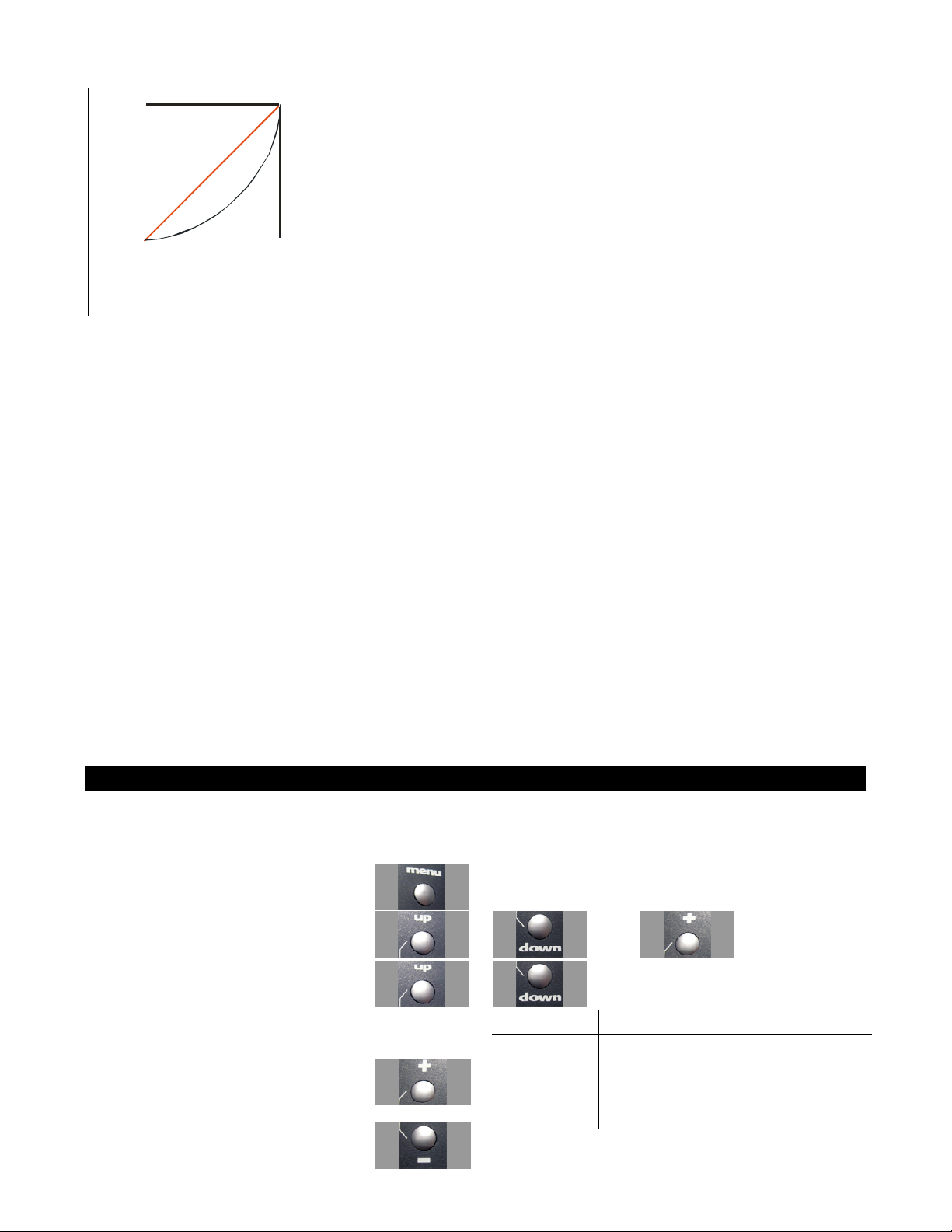
Fu ll br ake
0% (linear)
1~1 00%
(quick)
+ve exponential
(quicker response)
Neutral
Servo travel
BRAKE
A positive (+ve) exponential value gives a quicker
braking response near the throttle neutral point,
making it MORE responsive to small braking
inputs, without changing overall throttle travel
like Dual Rate would.
Adjusting Brake Exponential
Use the navigation controls to adjust brake exponential as follows:
1. Access the top function menu from the
driving screen.
2. Navigate to the Throttle (Ch2) menu.
3. Navigate to Brake Expo.
4. Change the value.
or
or then
or
Value Description
0 Neutral braking response (linear).
-ve value
(-1 to -100)
+ve value
(1 to 100)
Milder braking response near neutral.
Quicker braking response near neutral.
Page 40

Throttle Sub-Trim
Throttle sub-trim adjusts the
center point of the throttle servo.
This differs from throttle trim in
that throttle sub-trim adjusts the
If you find that you have to use a large amount of throttle sub-trim to adjust the throttle position, you
should consider resetting the steering sub-trim to 0 and re-adjusting the servo horn on the servo output
shaft.
servo’s entire travel range; by
moving the center point of the
servo, the throttle and brake end
points (throttle, brake) stay the
same relative “distance” from the
servo center.
Throttle sub-trim should be
initially adjusted before using
throttle trim, which is used to
make fine adjustments to center
the throttle within the total
steering range.
Adjusting Throttle Sub-trim
Use the navigation controls to adjust throttle sub-trim as follows:
Page 41
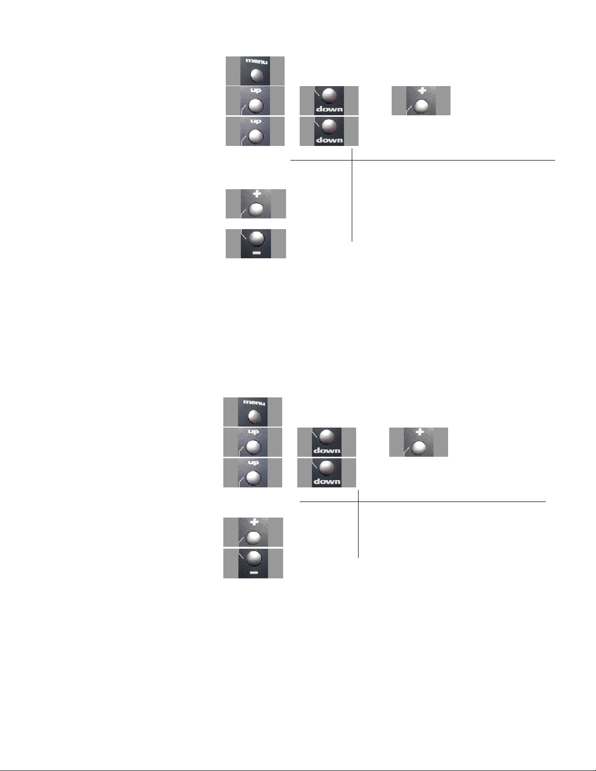
1. Access the top function menu from
the driving screen.
2. Navigate to the Throttle (Ch2) menu.
3. Navigate to Sub Trim.
4. Change the value.
or
or then
or
Value Description
0 Throttle sub-trim is centered within the servo
range.
-ve value
(-100 Æ -1)
+ve value
(1 Æ 100)
Throttle sub-trim is to the BRAKE end.
Throttle sub-trim is to the THROTTLE end.
Trim and EPA Interaction
A trim (or sub-trim) setting of 100 is equivalent to an End point setting of 50.
Adjusting Throttle Dual Rate Increment
Use the navigation controls to adjust throttle dual rate increment as follows:
1. Access the top function menu from
the driving screen.
2. Navigate to the Throttle (Ch2) menu
3. Navigate to DR Increment.
4. Change the value.
or then
or
Value Description
Throttle dual rate value changes by set
increment.
1-20
or
Use smaller values for finer dual rate control.
Use larger values for coarser dual rate
control.
Page 42
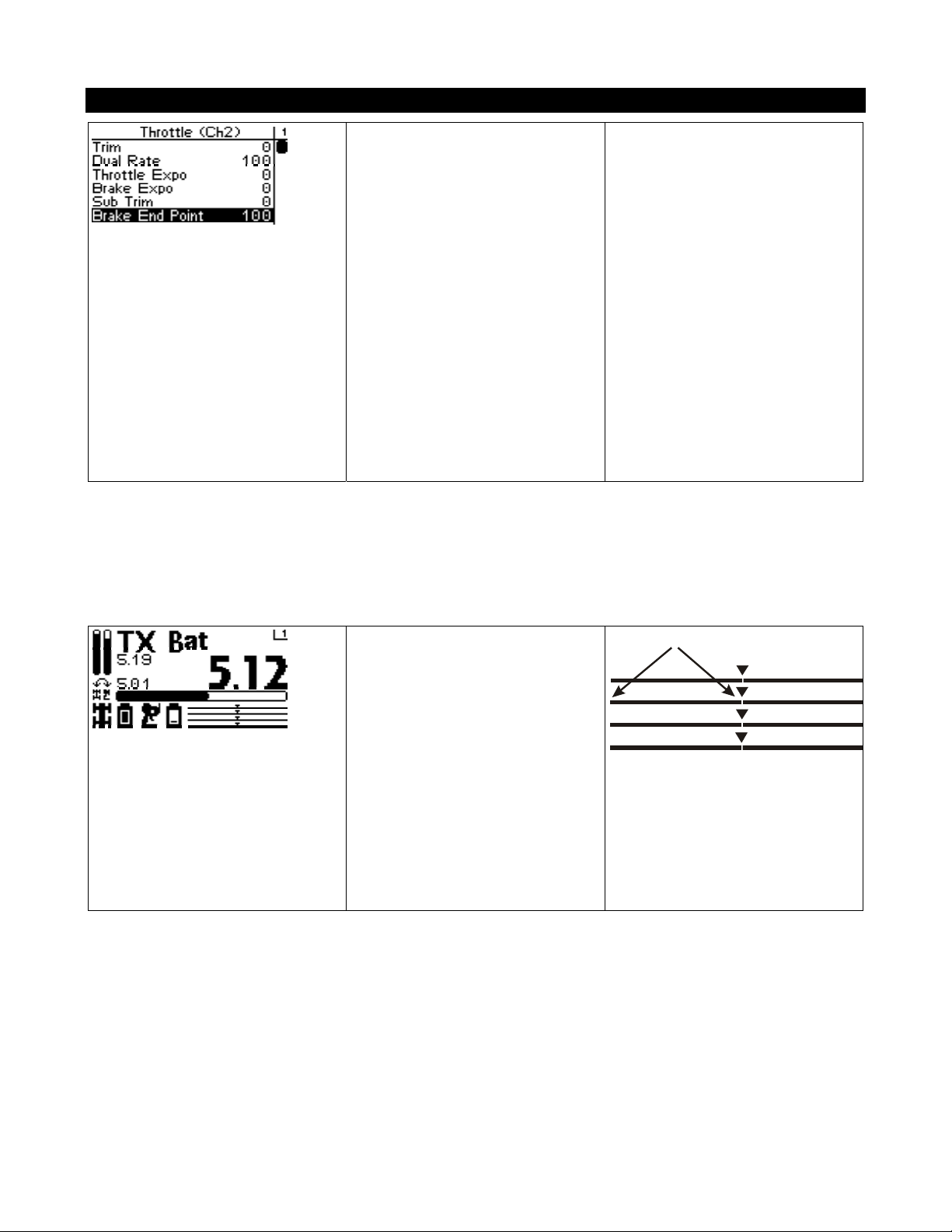
Brake End Point
The brake end point value
adjusts how far the throttle goes
to the BRAKE end with respect
to its full range of motion to the
brake end. End point adjustment
should be adjusted prior to other
throttle settings, as the brake end
point value affects other throttle
settings.
The brake end point is set
independently of the throttle end
point (which adjusts how far the
throttle moves to the
THROTTLE end).
The brake end point setting should be used to do the following:
Limit throttle throw to reduce mechanical binding or servo strain that may occur on full servo throw to
the brake end. For example, if the servo is trying to pull a mechanical brake linkage farther than it is
mechanically able.
Adjust braking range to reduce the full braking force of the vehicle.
On the driving screen, the brake
end point is represented by the
length of the bar to the left of the
pointer on the middle bar. The
greater the left length of the bar,
the greater the brake end point
value.
The position of the pointer on
the bar is affected by end point
settings (throttle and brake) and
trim setting.
Brake End Point
Page 43
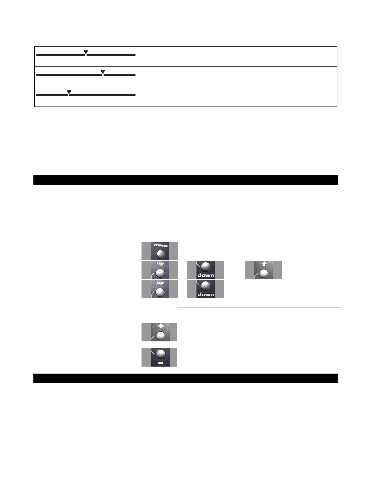
Changing the brake end point value has the following visual effect on the driving screen bars.
Brake end point value is approximately the same
as the throttle end point value.
Increased brake end point value (more servo travel
for BRAKING is possible).
Decreased brake end point value (less servo travel
for BRAKING is possible).
The position of the pointer on the bar is affected by end point settings (throttle and brake) and trim
setting; increasing the brake end point value may visually appear to have the same effect as decreasing
the throttle end point value.
An end point setting of 100 (the default) is typical for most servos, and should always be used for
ESCs. Larger setting values will overdrive most servos
Adjusting the Brake End Point
The brake end point value is a relative value, and is expressed as the percentage of full travel to the
BRAKE end. For example, setting the brake end point value to “100” allows the throttle to go to only
50% of full brake.
Use the navigation controls to adjust the brake end point as follows:
1. Access the top function menu from the
driving screen.
2. Navigate to the Throttle (Ch2) menu.
3. Navigate to Brake End Point.
4. Change the value.
or
or then
or
Value Description
0
1-200
200
Minimum brake end point; allows NO brake
travel.
Brake end point value is set to a percentage of full
braking travel.
Maximum brake end point (will overdrive most
servos)
Trim and EPA Interaction
A trim (or sub-trim) setting of 100 is equivalent to an End point setting of 50.
Page 44
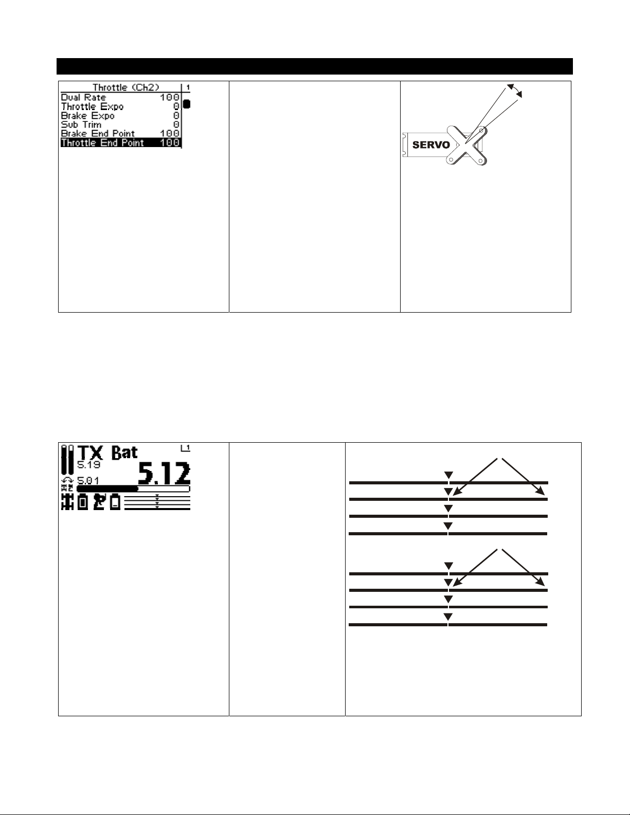
Throttle End Point
n
C
n
C
The throttle end point value
adjusts how far the throttle goes
to the THROTTLE end with
respect to its full range of motion
The throttle end point setting should be used to do the following:
to the throttle end. End point
adjustment should be adjusted
prior to other throttle settings, as
the throttle end point value
affects other throttle settings.
The throttle end point is set
independently of the brake end
point (which adjusts how far the
throttle servo turns to the
BRAKE end).
Limit throttle throw to reduce mechanical binding or servo strain that may occur on full servo throw to
the throttle end. For example, if the servo is trying to pull a mechanical throttle linkage farther than it is
mechanically able.
Adjust throttle range to reduce the top speed of the vehicle.
On the driving screen,
Throttle End Point
the throttle end point
is represented by the
length of the bar to
the right of the
pointer on the middle
bar. The greater the
Throttle End Point
Steeri
Throttl
Shift (
Ch4
right length of the
bar, the greater the
throttle end point
value.
The position of the
Steeri
Throttl
Shift (
Ch4
pointer on the bar is
affected by end point
values (throttle and
brake) and trim
setting.
Page 45
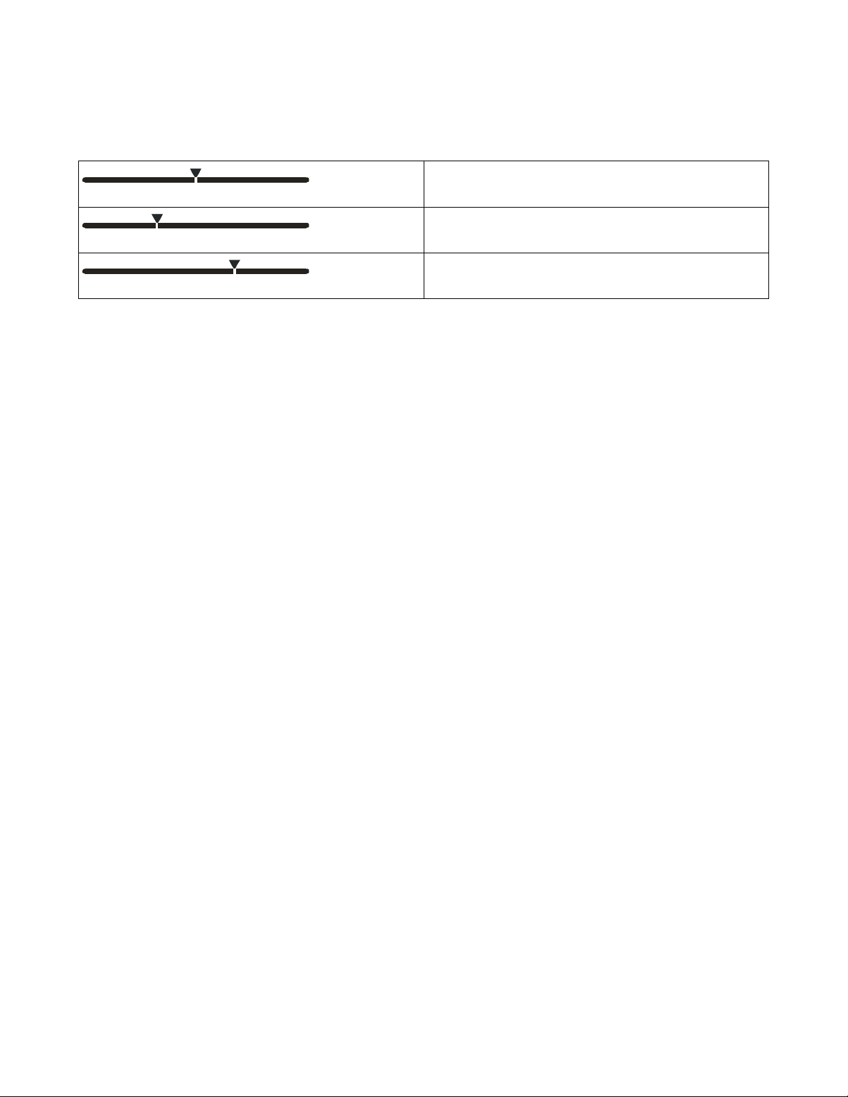
Changing the throttle end point value has the following visual effect on the driving screen bars.
Throttle end point value is approximately the
same as the brake end point value.
Increased throttle end point value (more servo
travel for THROTTLE is possible).
Decreased throttle end point value (less servo
travel for THROTTLE is possible).
Page 46
The position of the pointer on the bar is affected by end point values (throttle and brake) and trim
setting; increasing the throttle end point value may visually appear to have the same effect as
decreasing the brake end point value.
An end point setting of 100 (the default) is typical for most servos, and should always be used for
ESCs. Larger setting values will overdrive most servos
Adjusting the Throttle End Point
The throttle end point value is a relative value, and is expressed as the percentage of full travel to the
THROTTLE end.
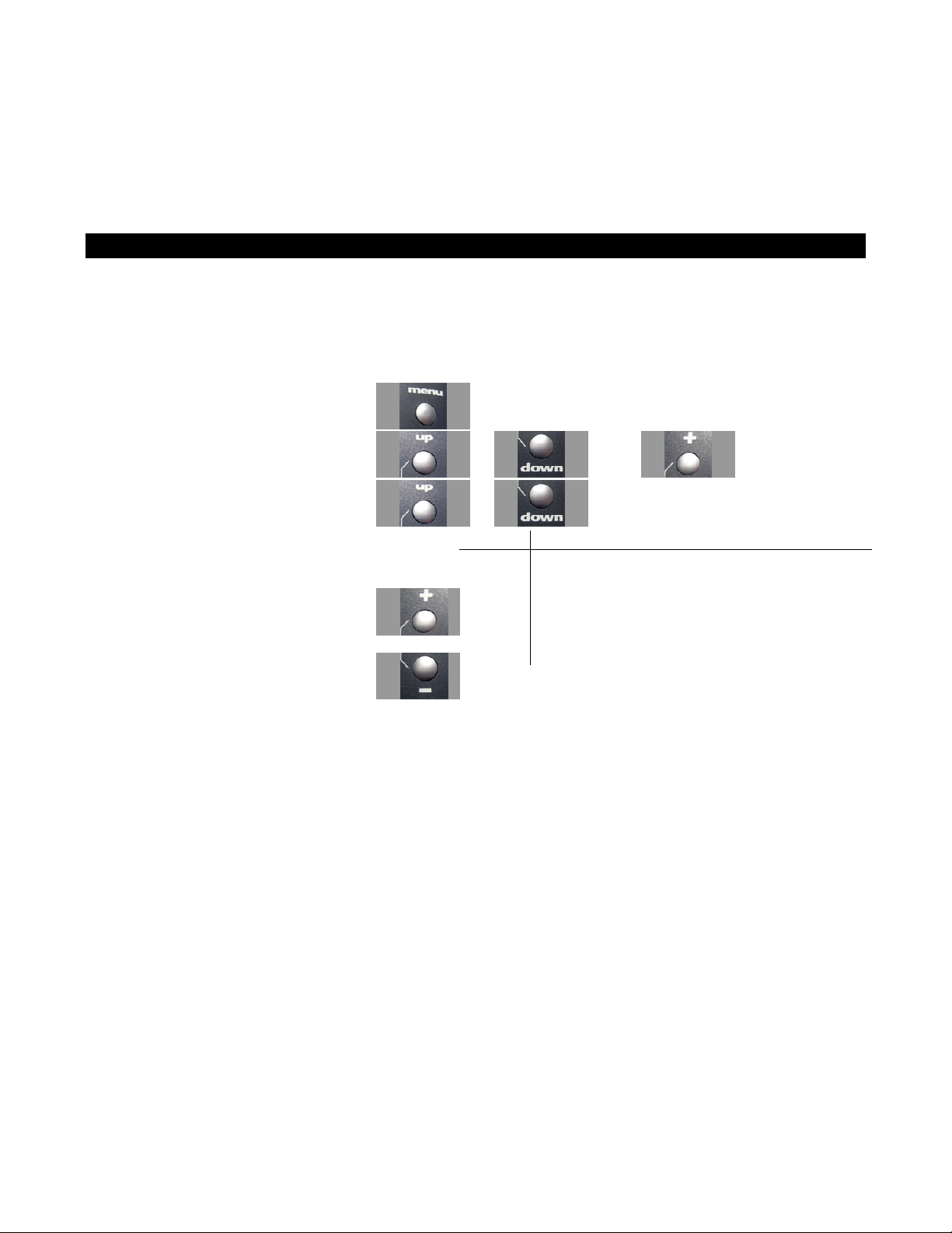
Use the navigation controls to adjust the throttle end point as follows:
1. Access the top function menu from the
driving screen.
2. Navigate to the Throttle (Ch2) menu.
3. Navigate to Throttle End Point.
or then
or
Value Description
0 Minimum throttle end point; allows NO throttle.
4. Change the value.
or
1-199
200
Throttle end point value is set to a percentage of full
throttle travel.
Maximum throttle end point (will overdrive most
servos)
Page 47
Trim and EPA Interaction
A trim (or sub-trim) setting of 100 is equivalent to an End point setting of 50.
Throttle Dual Rate Mode
Dual Rate Mode controls the behavior of the Dual
Rate setting for the throttle servo.
Changing the Throttle Dual Rate Mode
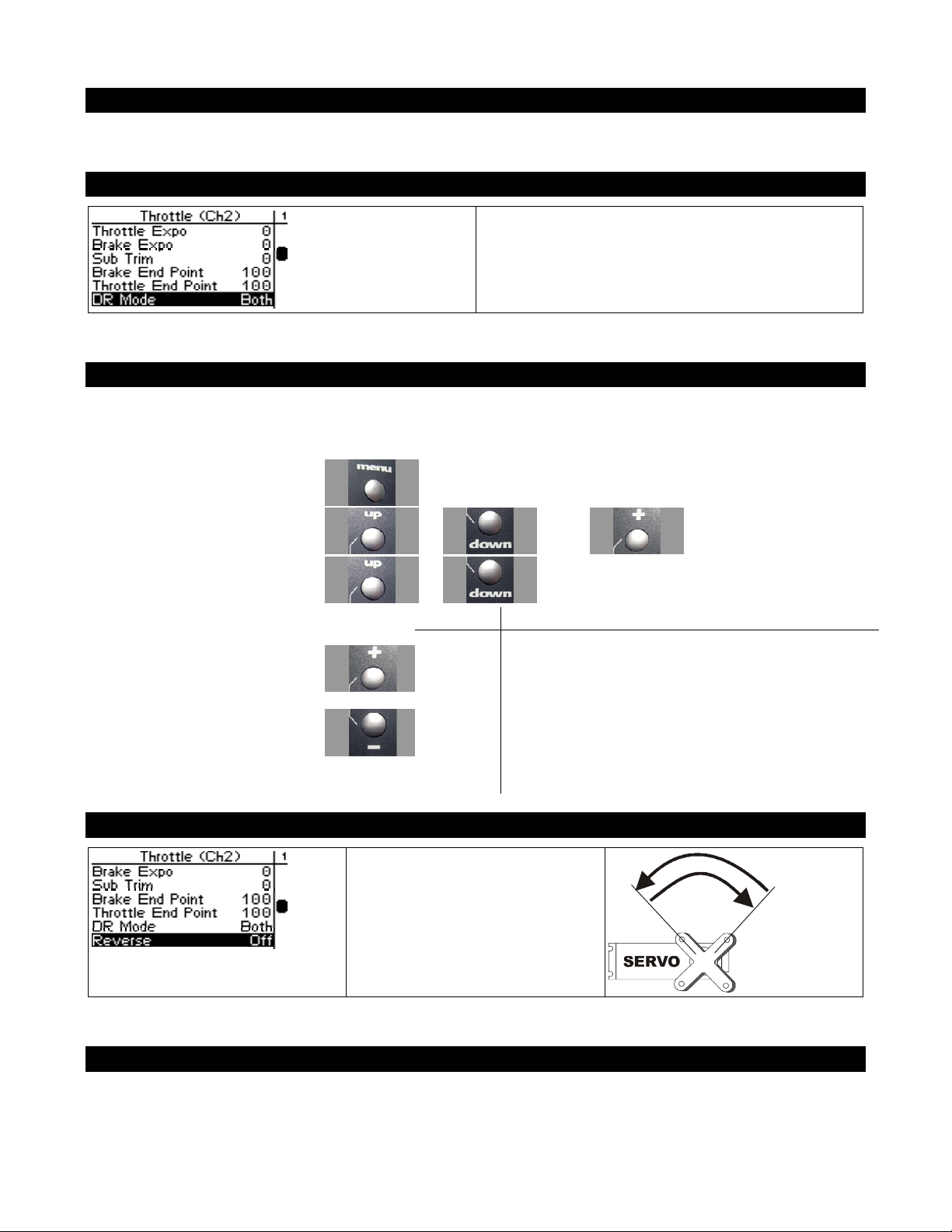
Use the navigation controls to change the dual rate mode as follows:
1. Access the top function menu
from the driving screen.
2. Navigate to the Throttle (Ch2)
menu.
or then
3. Navigate to DR Mode.
4. Change the value.
Throttle Servo Reverse
or
Value Description
Both Dual rate affects travel in both direction
or
Throttle
Brake
Dual rate affects throttle travel only. Useful to limit
throttle inputs early in a run with an electric model.
Dual rate affects brake travel only. Useful to adjust
brakes on a nitro vehicle without affecting throttle travel.
Throttle servo reversing reverses
the direction the throttle servo
moves upon receiving an input
from the throttle trigger.
Changing the Throttle Servo Reverse Setting
Use the navigation controls to change the throttle servo reverse setting as follows:
Page 48
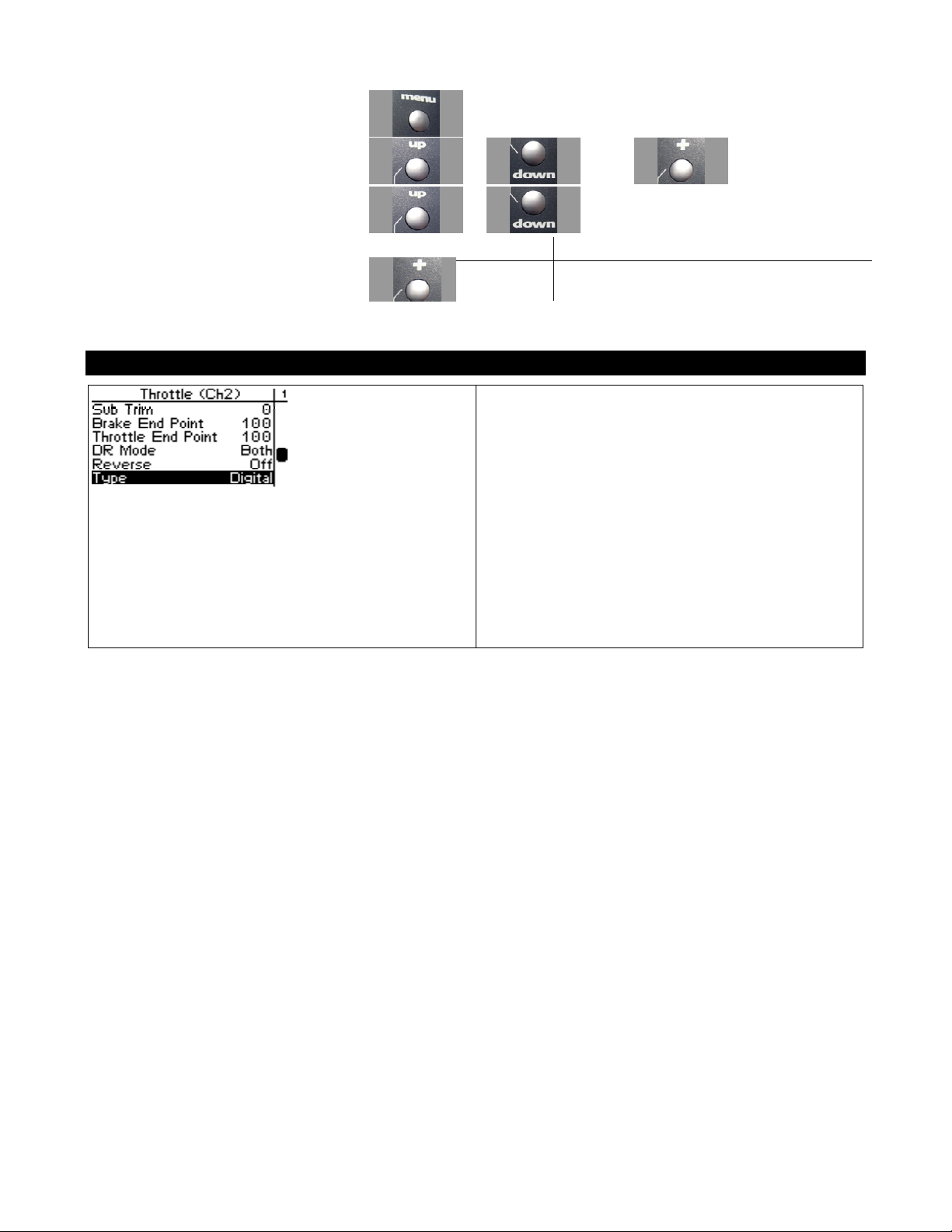
1. Access the top function menu from the
driving screen.
2. Navigate to the Throttle (Ch2) menu.
3. Navigate to Servo Reverse.
4. Change the value.
Throttle Servo Type
or then
or
Value Description
Off Standard servo direction.
On Reversed servo direction.
Throttle servo type lets you select the type of
throttle servo (analog or digital) in the vehicle.
Analog servos are sent signals at 50 frames/sec,
while Digital servos are sent signals at 100
frames/sec.
If you are running an electric car with an ESC, it
may perform better with the digital setting. Some
ESCs may not operate at all with the higher frame
rate. Try both settings and choose the best
performance.
Page 49
Changing the Throttle Servo Type
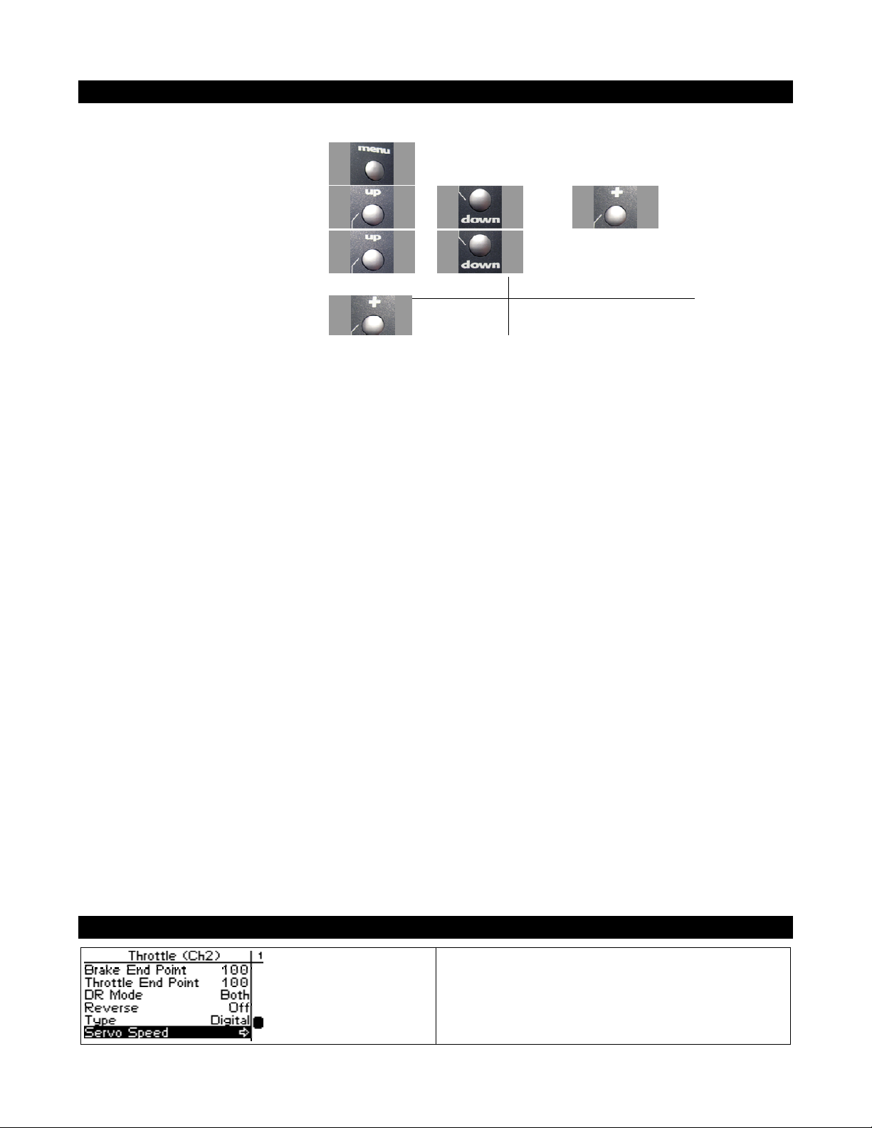
Use the navigation controls to change the throttle servo type as follows:
1. Access the top function menu from
the driving screen.
2. Navigate to the Throttle (Ch2) menu.
3. Navigate to Servo Type.
4. Change the value.
or then
or
Value Description
Analog Throttle servo is analog.
Digital Throttle servo is digital.
Throttle Speed
Throttle speed allows you to limit the maximum
speed that the throttle servo will be driven to
match your movements on the trigger. There are
four parameters that can be adjusted to precisely
 Loading...