

Page 1
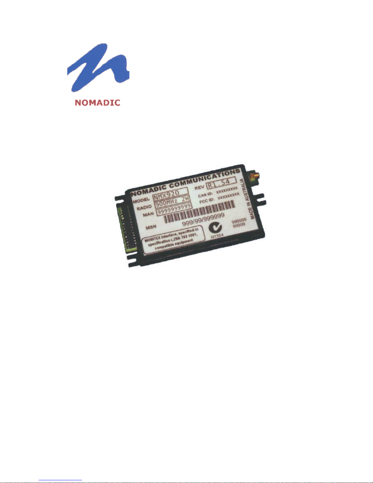
NOMADIC
COMMUNICATIONS
NMX920
OEM Integrators Guide
Version 1.02
December 1999
Page 2

NMX920 OEM Integrators Guide
Page 2 of 21
1. Record of Issue
Issue
Issued by Date Nature of Amendment(s)
1.0
BH 17.11.1999 Draft release
1.01
BH 26.11.1999 Added PCB layout dimensions for plug in
modem option.
1.02
BH 09.12.1999 Update of Modem I/O for improved performance
1.03
BH 03.01.2000 Added SAR compliance results
Any and all specifications are subject to change by Nomadic Communications Pty Ltd without notice except to the appropriate spectrum management authorities.
The information in this specification is deemed reliable at the time of printing. Nomadic Communications does not assume responsibility for any errors that may
appear in this specification nor any omissions that may have occurred at the time of printing. Interested parties must therefore rely on their own enquires. Nomadic
Communications does not assume liability arising from the application or use of any information contained in this document or the product referred to by this
document. Mobitex® is a registered trademark of Telia AB, Sweden.
Page 3

NMX920 OEM Integrators Guide
Page 3 of 21
2. Contents
1. Record of Issue ........................................................................................................ 2
2. Contents ..................................................................................................................3
3. Scope ......................................................................................................................4
3.1. Standards ......................................................................................................... 4
3.2. Applicability....................................................................................................... 4
4. Interface Notes......................................................................................................... 5
5. Physical Requirements ............................................................................................ 6
5.1. Dimensions....................................................................................................... 6
5.2. System Interface............................................................................................... 6
5.3. RF Port ............................................................................................................. 7
5.4. Power Supply.................................................................................................... 7
5.5. Board to Board Connection............................................................................... 9
6. Modes Of Operation............................................................................................... 10
6.1. Application of power........................................................................................ 11
6.2. Network Contact ............................................................................................. 11
6.3. Mode Change ................................................................................................. 11
6.4. Shutdown........................................................................................................ 12
6.5. Removal of power........................................................................................... 12
7. Notes for Integrators .............................................................................................. 13
7.1. Antenna .......................................................................................................... 13
7.2. Human Exposure Issues................................................................................. 13
7.3. Power Supply.................................................................................................. 14
7.4. Operational Notes........................................................................................... 15
8. Mobitex Compliance............................................................................................... 16
9. Technical Specification .......................................................................................... 18
10. Development Tools............................................................................................. 19
10.1. NMD920 Modem Evaluation Kit.................................................................. 19
10.2. ModmTest ................................................................................................... 19
11. Ordering Information........................................................................................... 20
12. References......................................................................................................... 21
Page 4

NMX920 OEM Integrators Guide
Page 4 of 21
3. Scope
The NMX920 Radio Packet Modem is a second generation product providing system
integrators access to 900 MHz Mobitex Networks.
This OEM Integrators Guide documents the behaviour and control of the NMX920 to
enable OEM designers to correctly and efficiently interface with the modem. This
document is concerned with the physical, interface and regulatory issues related to the
use of NMX920. It does not address the issues of good wireless application design, or
code generation, though references to these issues can be found in section ……
3.1. Standards
The NMX920 operates in the 900 MHz SMR (Specialised Mobile Radio) Band in
North America.
The NMX920 is designed to comply with established system and RF standards.
The standard documents listed here are for reference only, and are subject to
change or revision at any time.
Mobitex
Approval Standards: Mobitex Operators Association (MOA)
Documents: Mobitex Interface Specification, Revision R4A, October 1998
Approval Authority: BellSouth Wireless Data
USA
Approval Standards: Federal Communications Commission, FCC, USA
Documents: CFR47, Parts 2, 15, 90
Approval Authority: FCC
Canada
Approval Standards: Industry Canada, IC, Canada
Documents: RSS-119
Approval Authority: Industry Canada
3.2. Applicability
The content of this document is valid for the Nomadic Communications NMX920
Mobitex Radio Modem, with firmware versions greater than 2.01
Page 5

NMX920 OEM Integrators Guide
Page 5 of 21
4. Interface Notes
q Permanent damage can occur to the NMX920 if operated without a properly
connected 50-ohm antenna and cable (eg. RG-174). Care should be taken to ensure
that the antenna and cable are correctly matched to the NMX920.
q NMX920 must be properly subscribed with the approved MOBITEX Network
Operator in the country of intended operation before use. Care should be taken not to
operate an unregistered NMX920.
q When power is applied to the NMX920 power pins it will enter POWER-OFF MODE
(see section 6 below) waiting to sense a “power on request” via the correct assertion
of DTR pins (see section 6 below).
q When operated for the first time, via the correct assertion of the DTR pin (see section
6 below), the NMX920 may take several minutes as it attempts to become BORN on
its’ registered MOBITEX Network. Once BORN, the NMX920 will enter its default
mode, Battery Save or Express, as programmed at time of manufacture. The Mode
may be changed by the relevant MASC command.
q NMX920 should always be operated as described in this document, special attention
should be given to power handling detailed in section 6.
Page 6
NMX920 OEM Integrators Guide
Page 6 of 21
5. Physical Requirements
5.1. Dimensions
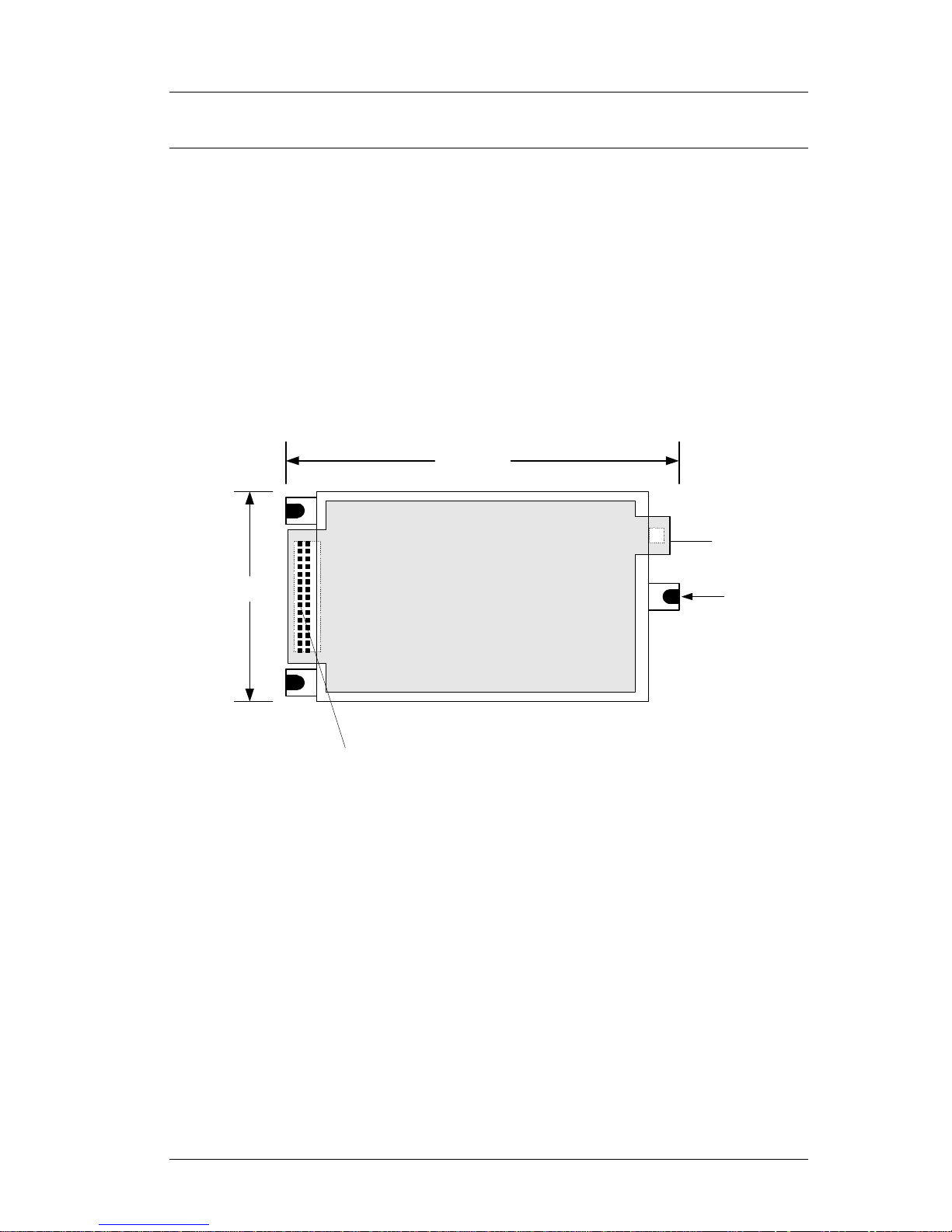
The overall dimensions of the NMX920 are provided below. It should be noted that
the NMX920 can be ordered with a variety of termination options. It is the
integrator’s responsibility to specify these options as required and maintain
sufficient space around the modem for cable access, if required.
The integrator is also required to maintain adequate ventilation about the NMX920.
The amount of ventilation required will be dependent on the worst case transmit
duty cycle that could be expected from the wireless application. Failure to provide
adequate ventilation will not damage the NMX920, but if power amplifier
temperature exceeds safe operating limits, the NMX920 will perform a controlled
shutdown.
MMCX
RF Connector
Locating pin x 3
NMX920
102 mm
System
Interface
30 Way
(2 x 15)
55 mm
12 mm High
1
2930
2
5.2. System Interface
The System Interface port on the NMX920 provides power, serial communication
and status indicators between the OEM device and the modem. In addition to the
user signals, there are a number of signals that are used for manufacturing
purposes. Only the signals listed below may be used for system interconnection.
All other signals should be ‘no connects’.
The standard system interface connector is a 2 x 15 x 2 mm pitch connector. The
NMX920 may be ordered with this connector mounted on the top for cable
interface, or underneath for board to board connection. Refer to the Ordering
Information.
The NMX920 is available with either a RS-232 serial interface, or a TTL (5V) serial
interface. This is an order time option, and is not retrofitable in the field. Refer to
the Ordering Information
Page 7

NMX920 OEM Integrators Guide
Page 7 of 21
Host Interface Connector
Pin# Pin Name Type/Direction1 Description
1-4 PWR VBAT Main power supply input
5-8 GND
GND Ground (Reference ground for all host interface
signals)
9 RXD
TTL/RS232 output
Main serial data receive (optional 5V TTL or
RS-232 DCE compatible output)
10 TXD
TTL/RS232 input
Main serial data transmit (optional 5V TTL or
RS-232 DCE compatible input)
11 DTR
TTL/RS232 input
System power-on control (optional 5V TTL or
RS-232 DCE compatible active edge triggered
input)
12 RFU No Connect2 Reserved for Future Use
13 RFU No Connect Reserved for Future Use
14 RFU No Connect Reserved for Future Use
15 /RADIO_LED Output Radio-on indicator (active low 5V TTL output)
16 /RX_LED Output Receive packet indicator (active low 5V TTL
output)
17 /MODE_LED Output Network mode indicator (active low 5V TTL
output)
18 /TX_LED Output Transmit packet indicator (active low 5V TTL
output)
19 /NET_LED Output Network contact indicator (active low 5V TTL
output)
20 /PWR_LED Output Power-on indicator (active low 5V TTL output)
21 NC No Connect
22 NC No Connect
23 SYSON
+5V_IN System power-on indicator (active high, high
impendence digital output)
24 EXTBAT - (Optional) Standby power supply input (4.75-
5.5VDC @ 100mA maximum)
25 NC No Connect
26 NC No Connect
27 NC No Connect
28 NC No Connect
29 NC No Connect
30 NC No Connect
1
Direction with respect to the Modem
2
All No Connects must be left Open Circuit
5.3. RF Port
The NMX920 is designed to operate with a 50 ohm antenna system. It is fitted with
a MMCX miniature RF connector. As an order time option, the RF connector may
be a straight connector mounted on the bottom of the modem for board to board
connection, or a right angle connector on the top of the board pointing out, or
sideways. See Ordering Information for details.
5.4. Power Supply
Careful consideration must be given to the power supply design for the NMX920.
Whilst receive current is in the order of 100 mA, the transmitter requires 1.7 A
Page 8
NMX920 OEM Integrators Guide
Page 8 of 21
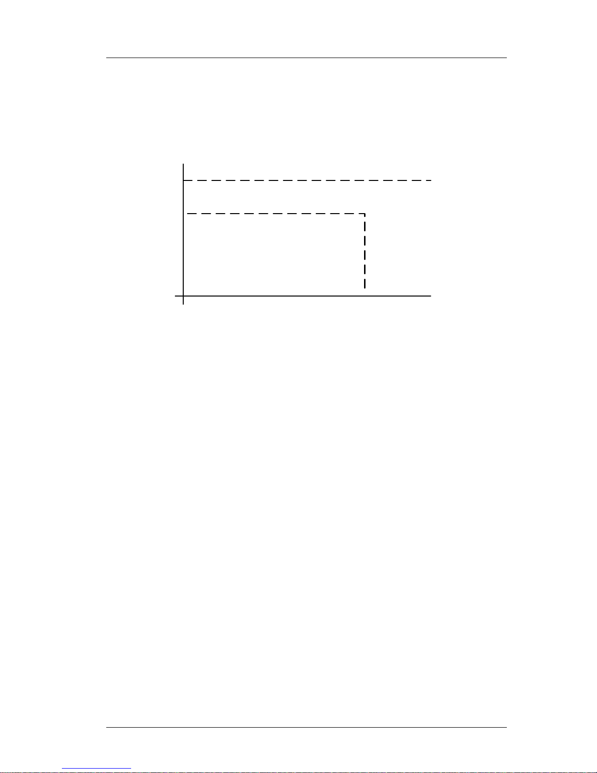
during transmission. This current must be available instantly; the modem has less
than 15 msec to change from receive mode to transmit mode, and at this point the
power amplifier has finished its startup sequence. Additionally, the power supply
must be able to provide this current without voltage sag for a maximum length
transmission, about 980 msec. The OEM power supply should fall within the
following template for reliable modem operation.
7.5v
6.5v
2000mA
OUTPUT
CURRENT
OUTPUT
VOLTAGE
The output voltage must stay within these limits for any transient load change
greater than 10uS.
Page 9
NMX920 OEM Integrators Guide
Page 9 of 21
5.5. Board to Board Connection
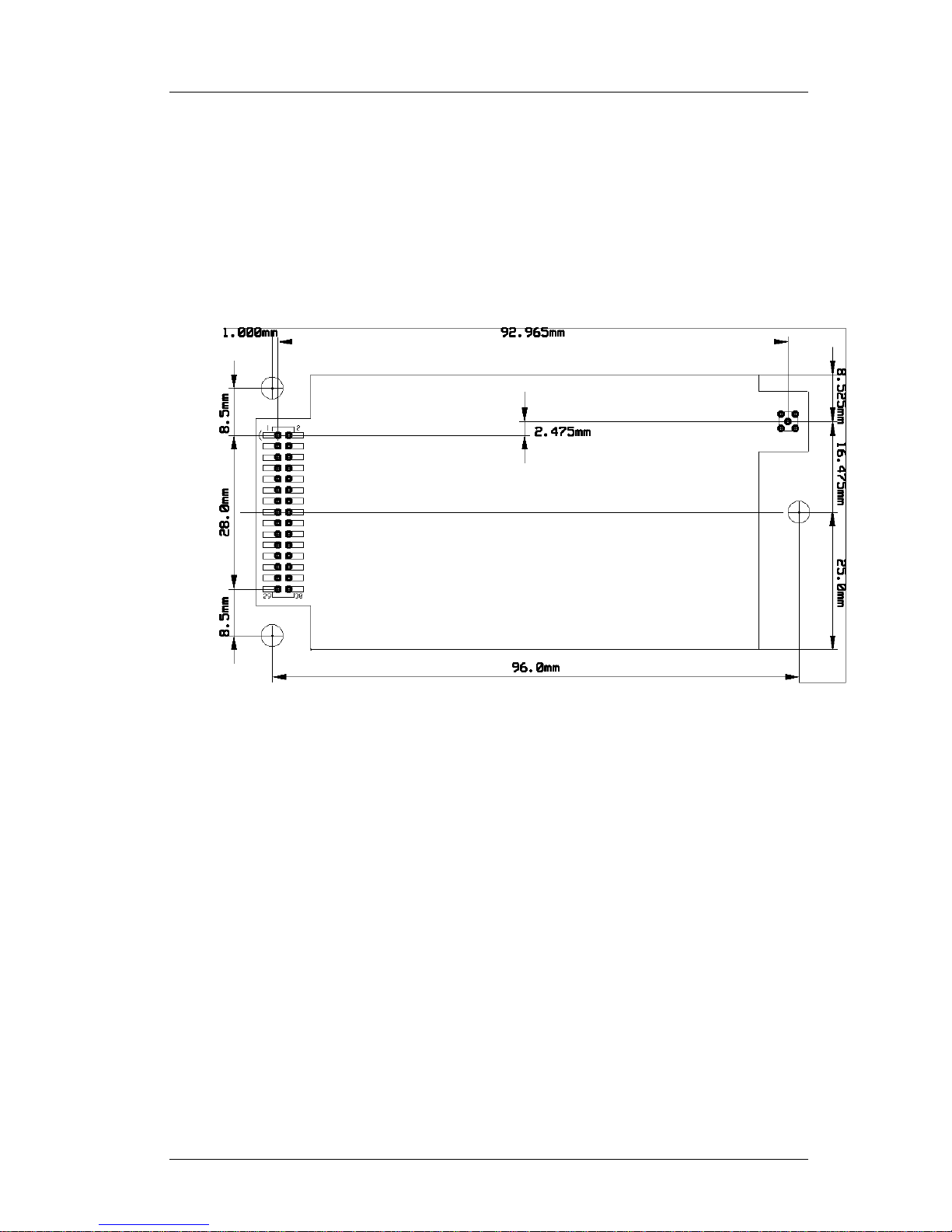
The NMX920 is available in a direct board to board configuration. In this
configuration, the NMX920 mates directly with system interface and RF connectors
in on the OEM system. This configuration eliminates all modem cabling, resulting
in significant cost savings, and ease of assembly. This option is available at time
of ordering.
The dimensions of the required layout on the host unit are shown below.
Additionally electronic versions of this layout in CADINT format ise available from
Nomadic Communications for import into the system integrator’s CAD system.
Recommend Interface Connectors for Board to Board configuration
RF connector is a PCB surface mounted MMCX male, Part No. Johnson 135-3801-
201 straight plug receptacle or equivalent.
System Interface Connector is a surface mounted 2 x 15 x 2mm plug, Part No.
Samtec TMMH-115-01-S-DV-ES, or equivalent.
Page 10
NMX920 OEM Integrators Guide
Page 10 of 21
6. Modes Of Operation
The NMX920 is a microprocessor controlled, hybrid electronic device with special
requirements for power quality and application. The NMX920 is designed to operate with
power applied to the External Interface at all times, and provides the ability to power
itself on and off under software and hardware control. Because of the nature of radio
transmissions, and the MOBITEX network, the NMX920 needs to be able to control its
own powering down to ensure that certain time–critical processes are completed and the
system is left in a known state. If possible, OEM designers should provide for this
behaviour by powering the NMX920 from a constant power source, or the same source
as the OEM equipment.
IMPORTANT!
Care should be taken not to remove power from the External
Interface without properly shutting down the NMX920 via the
MASC FO command. For further information see section “Power
Sequencing”
If power is removed from the External Interface, without correctly shutting down the
NMX920, the MOBITEX network will become unaware of the modem’s Active/Inactive
state. This situation is recoverable, however the sudden loss of power could result in loss
of buffered messages. This section outlines the procedures necessary to properly power
and control the NMX920.
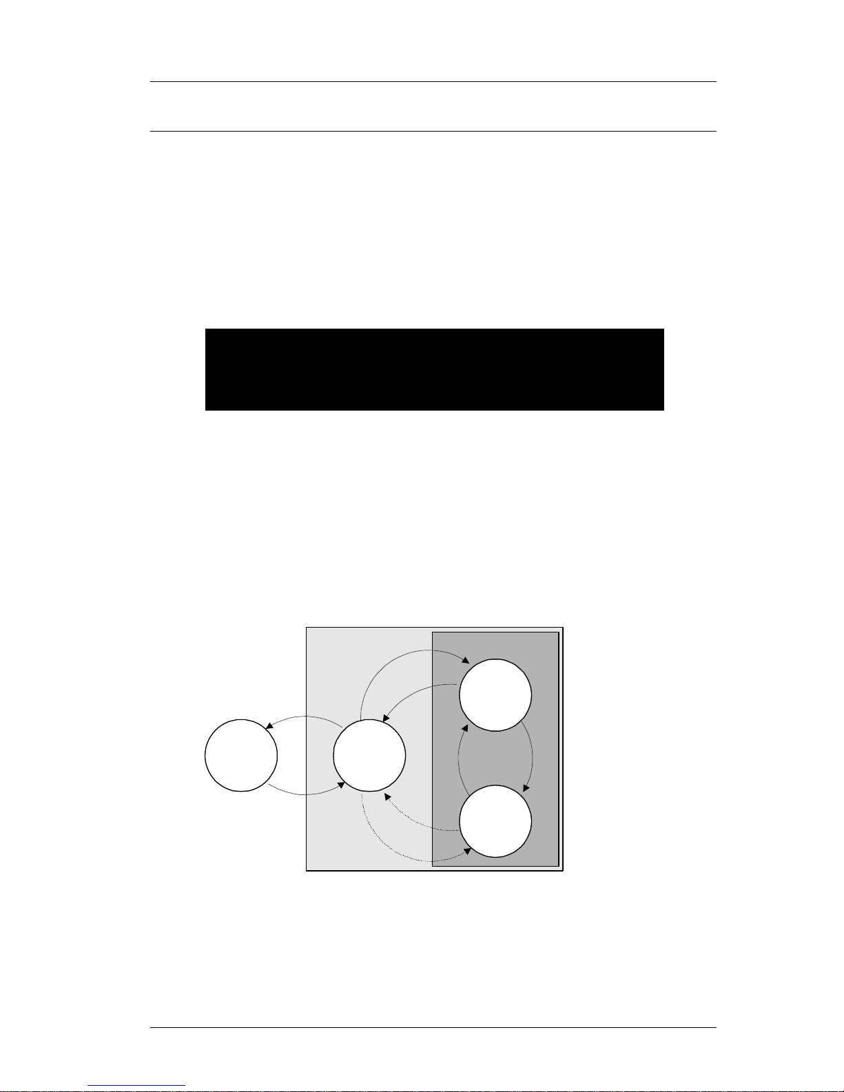
The following diagram outlines the relationship between the three power modes and the
mechanisms for changing between them.
The NMX920 operates in one of three distinct power modes while power is applied to the
External Interface; POWER-OFF MODE, BATTERY SAVE MODE and EXPRESS
MODE. To provide control over the operational state, and power consumption of the
NMX920, the OEM can change between these modes by issuing certain MASC
commands and/or electrically activating the DTR line on the External Interface.
NO
POWER
POWER-OFF
MODE
Removal
of power
BATTERY
SAVE MODE
EXPRESS
MODE
Mode
change
Mode
change
Shutdown
"Power-on
request"
Application
of power
Network Contact
Operational
Shutdown
"Power-on
request"
Page 11

NMX920 OEM Integrators Guide
Page 11 of 21
q POWER-OFF MODE – this mode is selected when the NMX920 is not required to
communicate with the MOBITEX network to send and/or receive messages, or the
NMX920 is to have its power disconnected. Power consumption is reduced to a
minimum in this mode by switching off most internal devices, including the
microprocessor and MASC interface. The NMX920 is waiting to sense a “power on
request” via the correct assertion of the DTR pin (see section …. above). This will
cause the NMX920 to enter its last known operational state (ie. either EXPRESS or
BATTERY SAVE MODE, whichever mode was active when POWER-OFF MODE
was entered.)
q EXPRESS MODE – in this mode the NMX920 the radio is always powered. Radio
conditions permitting, the NMX920 will contact and register with the MOBITEX
network and is able to send and/or receive messages. The NMX920 will enter
BATTERY SAVE MODE when the MASC FY command or MODE MPAK is issued.
Alternatively, the NMX will return to POWER-OFF MODE by issuing the MASC FO
command.
q BATTERY SAVE MODE - this mode is functionally similar to EXPRESS MODE
except that the Radio Module runs on about 10% duty cycle to reduce the average
power consumption.
6.1. Application of power
Electrical power must be applied to the NMX920 via the PWR pins of the External
Interface. The NMX920 will power-up, run internal diagnostics and then enter
POWER-OFF MODE. The designer should allow at least 2 seconds between the
application of power and the first attempt to communicate with the NMX920 to
change out of POWER-OFF MODE.
6.2. Network Contact
Once power has been applied according to Section 6.1 the NMX can be brought
into Network Contact (ie. either EXPRESS or BATTERY MODE) by toggling DTR
to it’s active state.
The NMX920 will issue a MASC B frame to initialise the MASC interface, and begin
MOBITEX network roaming and contact. From this point on the MASC interface is
active and controls the behaviour of the NMX920.
NOTE: Application of DTR for duration less than 1000ms will initiate internal
diagnostics and return to POWER-OFF MODE.
6.3. Mode Change
The NMX920 can toggle between EXPRESS MODE and BATTERY SAVE MODE
while in network contact using one of the following mechanisms:
1. MASC FY command is issued.
2. MODE MPAK issued at MASC interface.
The NMX920 will contact the network to toggle modes, this operation involves
packet transmission and can take up to two seconds.
Page 12

NMX920 OEM Integrators Guide
Page 12 of 21
6.4. Shutdown
The NMX920 can be placed back into POWER-OFF MODE by issuing the MASC
FO command.
The NMX920 will terminate MOBITEX network activities, send an INACTIVE to the
network, issue the MASC FO reply and shut down power to internal devices to
enter POWER-OFF MODE. It is important that the correct shutdown procedure be
used each time the modem is shutdown to prevent lose of buffered messages, and
to keep the network informed of the modem’s status.
The NMX920 can toggle between EXPRESS/BATTERY SAVE MODE and
POWER-OFF MODE by repeating sections 6.3 and 6.1.
6.5. Removal of power
The NMX920 controls the internal distribution of power from the PWR pins using
digitally controllable switches and regulators. While there is no mechanism for
completely disconnecting power from the NMX920 without externally removing the
power source from the interface, the NMX920 can enter a very low power state
(POWER-OFF MODE) under direct control. It is preferable to use this low power
mode rather than disconnecting power from the External Interface.
If power must be removed from the External Interface the following procedure
should be followed to ensure data integrity and network compatibility:
1. Shut down NMX920 via the MASC FO command.
2. Wait for MASC FO response from the NMX920 to indicate that it has shut
down.
3. Remove electrical power from the interface
Following this procedure will ensure that the network is properly notified and no
buffered messages are lost.
Page 13

NMX920 OEM Integrators Guide
Page 13 of 21
7. Notes for Integrators
Application developers should be aware of the following hardware firmware and
operational issues prior to commencement of integration of the NMX920. These issues
impact hardware design, application software and application certification by the network
operator.
7.1. Antenna
The NMX920 requires a 50 Ω matched antenna with a VSWR no greater than 1.5:1
over the transmission band.
The provision of the antenna system is the responsibility of the system integrator.
The design and location of the antenna system will be largely dictated by system
requirements, and may have system implications with respect to RF exposure, see
regulatory issues below. During certification testing, the NMX920 was tested using
a unity gain (dipole), ground independent antenna, and a printed circuit antenna of
proprietary design.
The unity gain (dipole), ground independent antenna used was manufactured by
ZCG Scalar has the following characteristics, but these characteristics are common
to both ground independent and ground referenced antennas from a number of
manufacturers.
Frequency 890 – 960 MHz
Gain Unity, (0 dBd)
Mounting Straight Connection TNC
Power 5 Watts
Impedance (Nom.) 50 Ohm
Polarisation Vertical polarisation
Construction Delrin, brass and steel
Tuning Factory
7.2. Human Exposure Issues
The NMX920 has been evaluated for human exposure to RF radiation under
Specific Absorption Rate (SAR) guidelines by APREL Laboratories. The NMX920
was battery powered, and utilised the antenna detailed above. The NMX920 was
run with development firmware which restricted the maximum transmit duty cycle to
9%. All production with firmware above R2.00 are limited to a maximum of 9%
transmit duty cycle. This parameter is not alterable in the field. The configuration
used for SAR testing was
• NMX920, pre-production sample (DUT)
• 7.2 V Li-Ion battery pack
• DYNMAST A-409T 800-900 MHz vertical handheld antenna (described above)
The results of the SAR testing are summarised as
“The maximum Specific Absorption Rate (SAR) averaged over 1 g, determined at
901MHz (high channel), of the Nomadic Communications OEM radio modem,
NMX920, is 1.41 W/kg when operating with an 9 % duty factor. The overall margin
Page 14

NMX920 OEM Integrators Guide
Page 14 of 21
of uncertainty for this measurement is ± 16.2 % (Appendix C). The SAR limit given
in the FCC 96-326 safety guideline is 1.6 W/kg. This unit as tested, and as it will be
marketed, is found to be compliant with this requirement”
The complete SAR report is available on request from Nomadic Communications.
If the final integration uses a different antenna configuration, the entire system will
need to be re-evaluated for human exposure to RF radiation. Human exposure to
RF radiation is a very complex system issue. It is affected by parameters (but not
limited to) such as
− Antenna
− Power Supply
− Application
− Case
− Accessories
− Antenna placement.
If the complete system is operated in a fixed location, mobile application or
portable application with a unity gain (0 dBd) antenna and a guaranteed minimum
separation of at least 20 cm between the antenna and any body then the NMX920
can be used in the system without further evaluation.
If a higher gain antenna is used then Maximum Permissible Exposure guidelines
must be checked, and application possibly made for change in licence conditions.
If the NMX920 is to be used in a body worn application, or if a 20 cm separation
between antenna and body cannot be guaranteed by obstruction, then the entire
integrated system must be re-evaluated for SAR. SAR evaluation will need to be
done for all available options for the final systems – all different battery packs,
cases, antennas, power supplies, attached peripherals, after market accessories
etc.
7.3. Power Supply
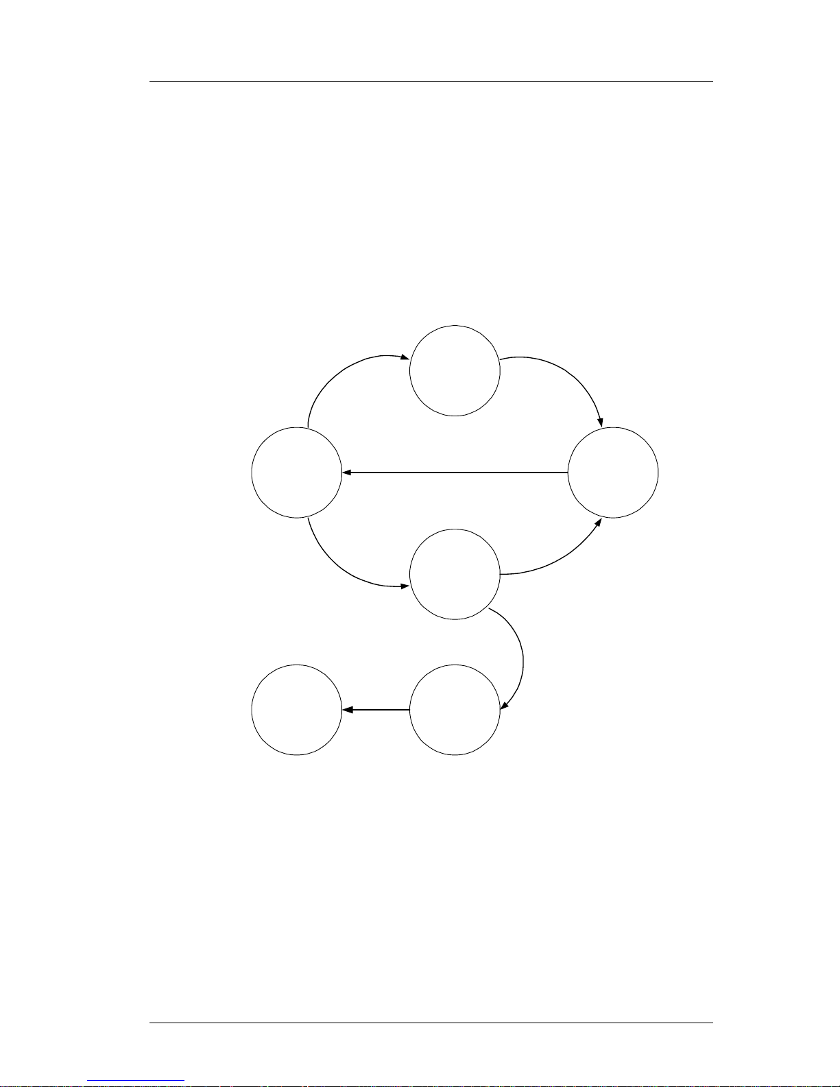
The NMX920 firmware monitors it’s power supply. If the modem’s power supply
falls outside the specified operating limits, the transmitter will be disabled and the
DTE notified. MASC packets appropriate to power supply management are
Page 15
NMX920 OEM Integrators Guide
Page 15 of 21
− F KF7. Power Supply voltage above safe operating limits. No transmission
possible (and also receive unable to complete), but MASC port still active.
− F KFB. Power Supply voltage below specified operating limits. No
transmission possible (and also receive unable to complete), but MASC
port still active.
− F KFB followed by F O. Power Supply voltage so far below specified
operating limits that the entire modem shuts down.
− F K F1. Modem’s power supply has been returned to nominal voltage.
The following diagram outlines the relationship between the voltage monitoring
states, the mechanisms for changing between them, and the MASC traffic
generated.
PWR
High
Normal
Mode
PWR > 7.5 V
PWR < 7.5 V
Periodic
MASC
F KF7
MASC
F KF1
PWR
Low
PWR < 6.5 V
Periodic
MASC
F KFB
PWR > 6.5 V
PWR < 5.5 V
MASC
F O
Shut
Down
7.4. Operational Notes.
− In the case of abrupt power outage, the modem does not save buffered
messages. It does, however, preserve all system parameters allowing the
modem to return to the network contact once power has been restored
− The NMX920 fully complies with the BellSouth Wireless Data requirements
for network delivered Lethal Injection. If the NMX920 is operating on the
BellSouth network, receipt of a Lethal Injection will render the modem
inoperable, requiring reactivation at a service centre or factory. Changing
networks (F R or F 03) does not reset this condition
− MASC frames exceeding 1150 bytes are ignored by the modem
Page 16

NMX920 OEM Integrators Guide
Page 16 of 21
8. Mobitex Compliance
The NMX920 is in conformance with the Mobitex Interface Specification (MIS) R4A.
When operated on the BellSouth Mobitex network it also meets the BellSouth Mobitex
extensions for Wireless Subscription Management (WSM). The NMX920 has been
validated against the BellSouth test specification ‘Radio Modem Certification Test
Specification, Version 5.1 BellSouth Wireless Data USA, December 11, 1998 (Doc. No.
BSWD-031-RMC-TS).
The MASC packets supported by the NMX920 in Production and Engineering versions
are summarised below.
Description Production
R2.01
Engineering
V2.01
B MASC protocol parameters Full Full
M Send and receive MPAK Full Full
E Error packet Full Full
N Return of MPAK not sent to
network
Full Full
R Return of incorrect MPAK Full Full
T Request or set alert text Full Full
U Issue alert MPAK Full Full
X User command Not used Not used
Y User command Not used Not used
Z User command Not used Not used
F A Power save mode functions Full Full
F B Change to Mobitex
operation mode
Not supported Not supported
F C Set up Mobitex line
connection
Not supported Not supported
F D Set up telephone line
connection
Not supported Not supported
F E Disconnect the line
connection
Not supported Not supported
F F Modem is in network
contact
Full Full
F G Modem is out of network
contact
Full Full
F H MPAK has been sent to
network
Full Full
F I Cancel MPAK Full Full
F J Print current MANs Not supported Not supported
F K Error packet Full Full
F L Activate external call
indication
Not supported Not supported
F M Transmitter on/off Full Full
F N Change to manual radio
mode
Not supported Not supported
F O Close down radio modem Full Full
F P Terminal MAN Full Full
F Q MASC device identity Full Full
F R Change network identifier Full Full
F S Change of traffic area Full Full
F T Change the temporary
channel list
Full Full
Page 17

NMX920 OEM Integrators Guide
Page 17 of 21
F U Power control for separate
radio module
Not supported Not supported
F X Change MASC
communication parameters
Full Full
F W RLSD control signal Not supported Not supported
F Y Battery saving mode control Full Full
F Z Product information Full Full
F 01 Network contact status Full Full
F 02 Subscription information Full Full
F 03 Change network by name
and ID
Full Full
QA01 Area list information Full Full
QA02 Roaming parameters
information
Full Full
QA03 Lock on channel pair Full Full
PA01 Radio protocol parameters No Full
PA02 Modem identity parameters No Full
PA03 Default channel list
parameters
No Full
PA04 Power control parameters No Full
PA05 Channel numbers
evaluated and scanned
Full Full
PA06 Radio parameters and
tests
Qualified: Loudspeaker
and speech commands not
supported
Qualified: Loudspeaker
and speech commands not
supported
PA07 Battery-saving protocol
parameters
No Full
PA09 Invalid list report No Full
PA10 MODE/SKIPNUM
parameters
Full Full
KAB Lock on FBI Full Full
KAM Lock on down channel Full Full
KAS Lock on up channel Full Full
Page 18

NMX920 OEM Integrators Guide
Page 18 of 21
9. Technical Specification
Radio Transceiver Specification
General Dual conversion receiver, directly modulated transmitter utilising common
antenna and solid state transmit/receive RF switch.
Modulation Technique NRZ GMSK (BT=0.3)
Transmitter Frequency Range 895 – 905 MHz (800 channels)
Receive Frequency Range 931 – 941 MHz (800 channels)
Channel Spacing 12.5 kHz
Frequency Accuracy
±1.2 kHz over full operating temperature range
Receiver Sensitivity -116 dBm
Transmitter Power (typical)
2 W @ 6.5 – 7.5 VDC into matched 50Ω antenna load at 20°C
Transmitter Power Control 4 level transmit power control (0, -6dB, -12dB and –18dB)
Antenna Cable Connector MMCX Female
Environmental Specification
Operating Temperature
-10°C to +55°C
Storage Temperature
-35°C to +80°C
Cooling Method Convection and thermal conduction of an enclosed environment
Operating Humidity
5% to 95% non-condensing relative humidity at +50°C for at least 8 hours
Physical Specification
Overall dimensions 100 mm x 55mm x 12 mm (standard enclosure) including connectors and
mounting lugs
Weight 70 g including standard enclosure
Mounting Method M2 Screws at 3 positions
Housing High density metallised plastic and stainless steel
Grounding Continuous-edge pressure fit grounding from case to PCB
Power Requirements
Supply Voltage 6.5 – 7.5 VDC
Supply Ripple Less than 35mV rms
All modes – Transmitting high power
1700 mA (typical) @ 7.0 VDC into matched 50Ω antenna at 20°C
Express Mode – Receiving
100 mA (typical) @ 7.0 VDC into matched 50Ω antenna at 20°C
Battery Saving Mode – Receiving
45 mA (ave) (typical) @ 7.0 VDC into matched 50Ω antenna at 20°C
Power-off Mode 250 uA (typical) @ 7.0 VDC
Device Interface
Connector 30-way 0.50 mm pitch FPC socket, or 2 x 15 x 2mm Board to Board
Connector, or cable
Data link protocol Mobitex® Asynchronous Communications Protocol (MASC1)
Data port RS-232 or TTL (Manufacturing Option)
Data rate 1200 – 9600bps
Specifications Subject to change
Page 19
NMX920 OEM Integrators Guide
Page 19 of 21
10. Development Tools
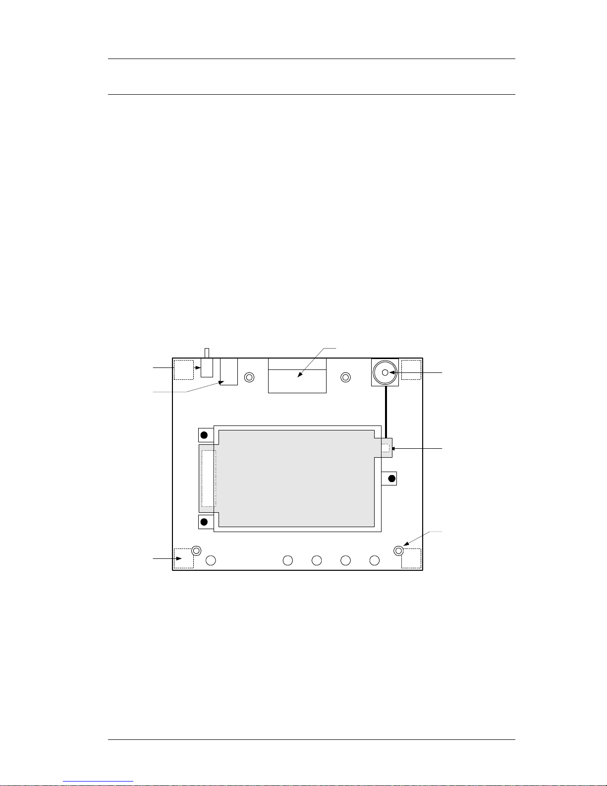
10.1. NMD920 Modem Evaluation Kit
The Nomadic Communications NMD920 Development Interface provides the
systems integrator a convenient platform from which to evaluate the operation
and performance of NMX920 Mobitex® Radio Packet Modems. The NMD920
provides an optimised power supply for the NMX920 series modems, socket for
antenna mounting and PC serial interface.
Key Features
q Power control and regulation for the modem
q Modem plugs directly onto NMD920.
q Connection to PC via 9 pin ‘D’ connector.
q TNC connector for mounting antenna, or coaxial cable to external antenna or
test instruments.
q LED indicators for modem status and power integrity.
NMD-920
Evaluation Kit
MODEM ON
NETWORK
CONTACT
TRANSMIT
EXPRESS
MODE
5.5mm barrel
socket (centre
positive)
Right angle
female DB-9
Push on/off
power switch
Johnson 1353801-201 straight
plug receptacle
POWER
APPLIED
Plated mounting hole x 4
NMX920
Rubber foot x 4
Board mount
straight TNC
female socket
10.2. ModmTest
Radio Modem Test Utility, Version 8.30. Copyright© RAM Mobile Data (May 1995)
Page 20

NMX920 OEM Integrators Guide
Page 20 of 21
11. Ordering Information
NMX F 2 0 W X Y Z / HH / S / C / O
Options
Blank = None
Configuration
Blank = None
Software Revision
Blank = Latest
Home Network
01 = United Wireless (400)
02 = STMD (400)
03 = BellSouth (900)
04 = Cantel (900)
Default Mode
E = Express
B = Battery
Antenna Connector Configuration
B = Bottom
S = Top Straight
R = Top Right Angle
System I/O
R = RS232
T = TTL
System Connector
T = Samtek 15 x 2 x 2mm Top Mount
B = Samtek 15 x 2 x 2mm Bottom Mount
F = FPC 30 x 0.5 mm
Network Frequency
4 = 400 MHz
9 = 900 MHz
Page 21

NMX920 OEM Integrators Guide
Page 21 of 21
12. References
− Mobitex Interface Specification (MIS), Revision R4A, October 1998.
− Mobitex Interface specification (MIS) R4A, Chapter 6, Revision G October 1998
− Technical Specification, WSM Modem Requirements, Rev A BellSouth Wireless
Data USA July 1998 (Doc. No. 98TR0021)
− Radio Modem Test Specification, Version 5.1 BellSouth Wireless Data USA
December 1998 (Doc. No. BSWD-031-RMC-TS)
− Federal Communications Commission (FCC) 47cfr, parts 2, 15, 90
− Industry Canada (IC) RSS-119 Issue 5, August 1996
- Certification Report on Specific Absorption Rate (SAR) Experimental Analysis
Nomadic Communications NMX 920 OEM Radio – Modem Date: 30 November,
1999. Aprel Laboratories
 Loading...