

NOMA Estate052-6964-6 Instruction Manual
READ AND SAVE THESE INSTRUCTIONS
052-6964-6
Estate 52" (132 cm) Ceiling Fan
Instruction Manual
2
Warning: To reduce the risk of personal injury, do not bend the blade arms (also referred to as flanges), when installing the brackets,
balancing the blades, or cleaning the fan. Do not insert foreign objects between rotating fan blades.
Warning: To reduce the risk of fire, electric shock or personal injury, mount fan to outlet box marked "acceptable for fan support" with
the screws provided with the outlet box.
Safety Rules–Read and Save These Instructions
1. To reduce the risk of electric shock, ensure electricity has been turned off at the circuit breaker or fuse box before installing.
2. All wiring must be in accordance with the national and local electrical codes. Electrical installation should be performed by a
qualified licensed electrician.
3. WARNING: To reduce the risk of electrical shock or fire, do not use this fan with any solid-state fan-speed control device. It will
permanently damage the electronic circuitry.
4. CAUTION: To reduce the risk of personal injury, use only the screws provided with the outlet box.
5. The outlet box and support structure must be securely mounted and capable of reliably supporting a minimum of 35 lb (15.9 kg).
Use only UL listed outlet boxes marked “FOR FAN SUPPORT.”
6. The fan must be mounted with a minimum of 7' (2.13 m) from the trailing edge of the blades to the floor.
7. Avoid placing objects in the path of the blades.
8. To avoid personal injury or damage to the fan and other items, be cautious when working around or cleaning the fan.
9. Do not use water or detergents when cleaning the fan or fan blades. A dry dust cloth or lightly-dampened cloth will be suitable for
most cleaning.
10. After making electrical connections, spliced conductors should be turned upward and pushed carefully up into the outlet box. The
wires should be spread apart with the grounded conductor and the equipment-grounding conductor on one side of the outlet box
and the ungrounded conductor on the other side of the outlet box.
11. All set screws must be checked and retightened where necessary before installation.
Warning: To reduce the risk of fire, electric shock, or personal injury, mount to outlet box marked "acceptable for fan support of 35 lb
(15.9 kg) or less" and use mounting screws provided with the outlet box. Most outlet boxes commonly used for the support of light
fixtures are not acceptable for fan support and may need to be replaced. Due to the complexity of the installation of this fan, a qualified,
licensed electrician is strongly recommended.
!
!
!
Attention: This product is equipped with a 190 W limiting device. If lamping exceeds 190 W the light kit will shut off automatically
until the proper wattage of bulbs is installed. Reset the light kit by turning it off, replacing the bulbs with the correct wattage, and then
turning the light kit back on.
!
IC ID: 4529A-FANHD
Operation is subject to the following two conditions:
(1) This device may not cause interference; and (2) this device must accept any interference, including interference that may cause
undesired operation of the device.
!
3
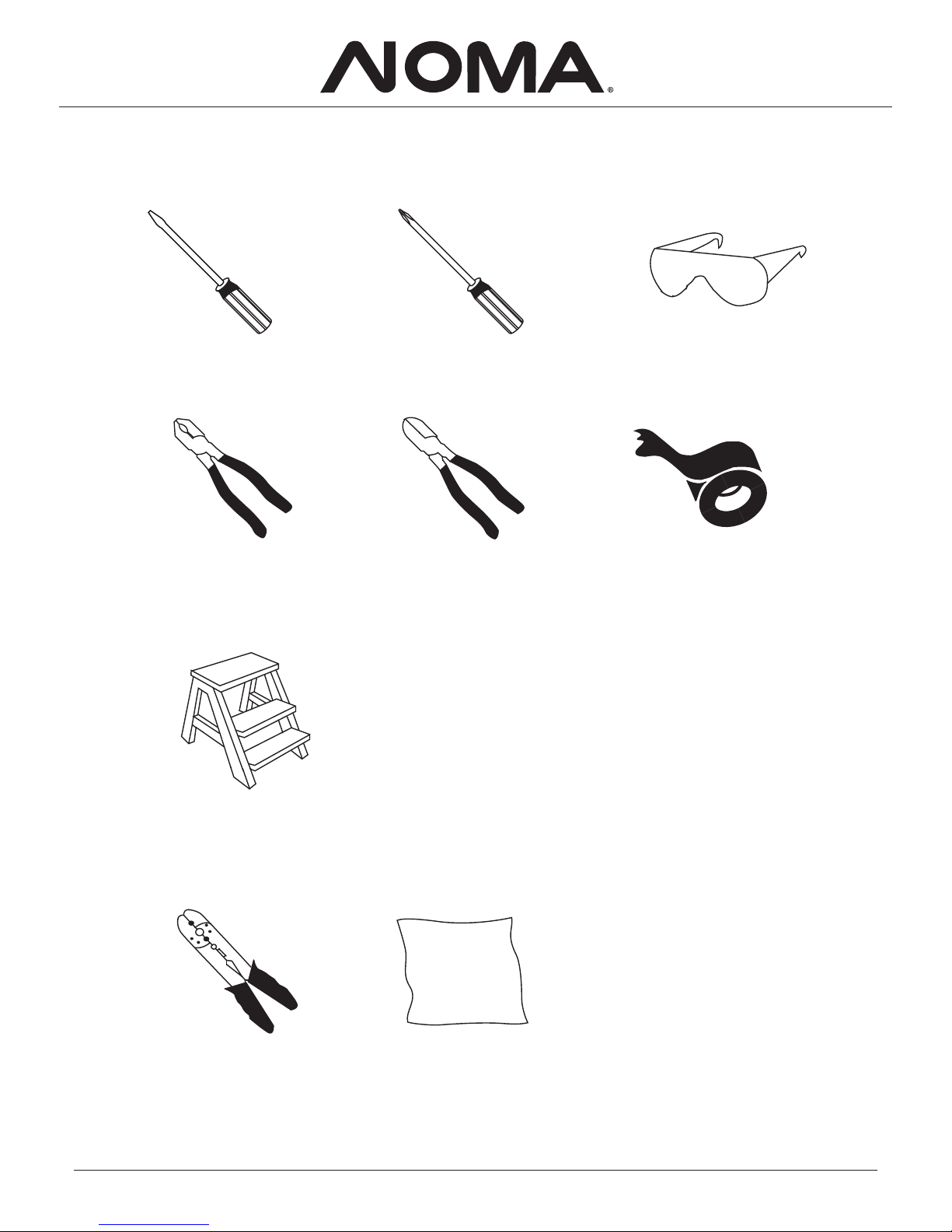
Required
Helpful
Flathead
screwdriver
Crosshead
screwdriver
Safety glasses
Pliers
Step ladder
Wire strippers
Wire cutters
Soft cloth
Electrical t ape
Tools Needed (not supplied)
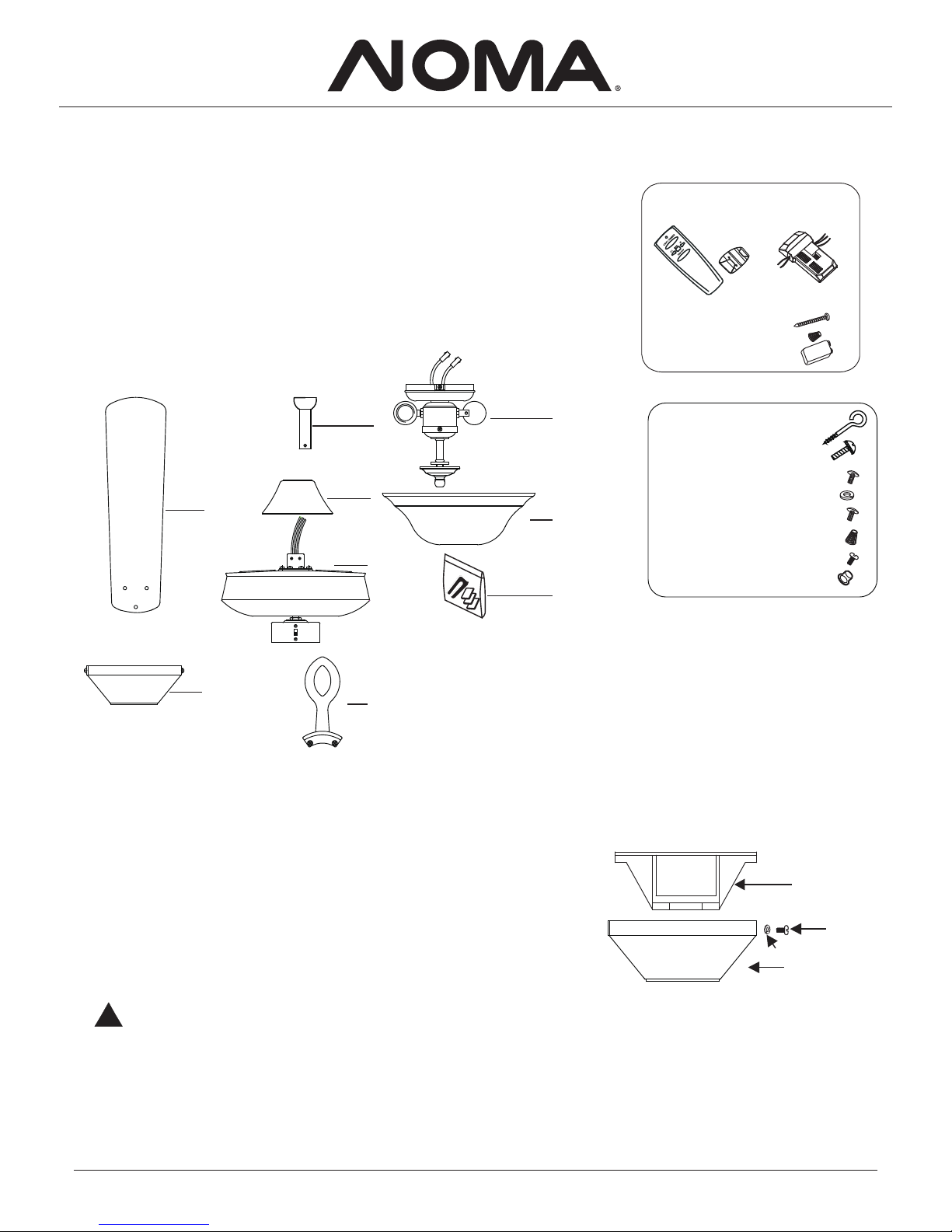
Unpacking Your Fan
Unpack and inspect fan carefully to be certain all contents are included.
1. Blades (5)
2. Canopy assembly
3. Ball/downrod assembly
4. Coupling cover
5. Fan motor assembly
6. Blade arms (5)
7. Light kit
8. Glass shade
9. Balance kit
4
1
2
3
8
9
7
4
5
6
Remote Control
Transmitter
& holder
Receiver
Hardware bag
Wood screws
Wire nuts
Battery
2 pcs
6 pcs
1 pc
Hardware bag
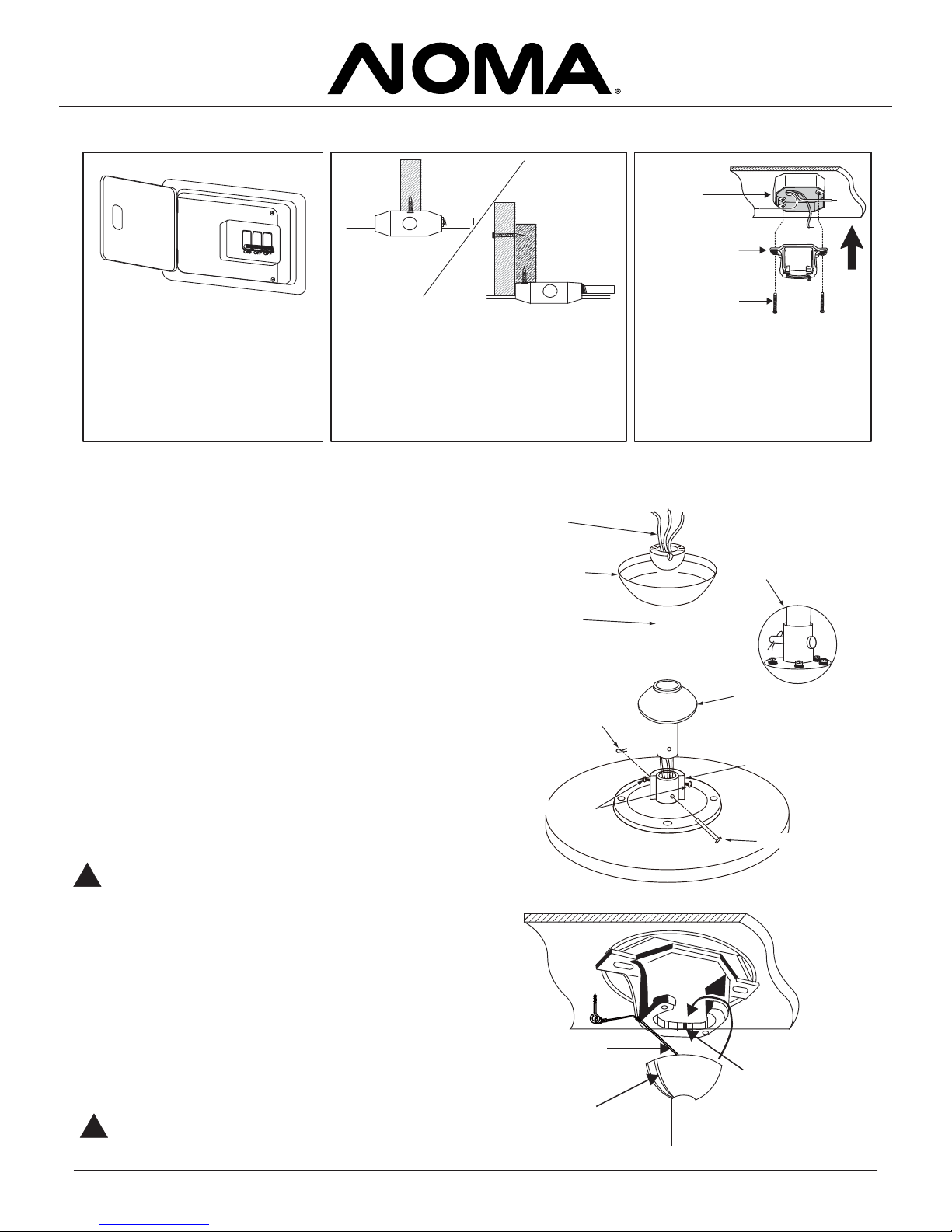
1. Remove the mounting bracket from the canopy by loosening the two
canopy mounting screws located in the “L-shaped” slots.
2. Remove and save the two canopy screws and washers in the round
holes. This will enable you to remove the mounting bracket.
Disassemble the Canopy Assembly
Fig. 1
Warning: Do not use the existing mounting bracket in the
outlet box; replace it with new mounting bracket.
!
Ceiling
mounting
bracket
Canopy
Canopy
mounting
screw
Washer
Blade arm screws 10 pcs
Blade screws 15 pcs
3 pcs
Wire nuts
Hook screws 1 pc
2 pcs
10 pcs
1 pcPlastic plug
4 pcsCanopy mounting screws
Spring washers
Mounting screws
5
REMEMBER to turn off the power. Follow the steps below to
hang your fan properly.
1. Remove the clevis pin, cotter pin and set screws from the top
of the motor assembly (see Fig. 5).
2. Route wires exiting from the top of the fan motor through the
coupling cover, canopy and then through the ball/downrod
(see Fig. 5).
NOTE: If a longer downrod (not included) is needed, take out
the screw located in the hanger ball, lower the hanger ball and
remove the pin, remove all 3 pieces from the downrod and
assemble them onto the new longer downrod before proceeding
to step 2.
3. Align the holes at the bottom of the downrod with the holes in
the coupling on top of the motor housing (see Fig. 5). Carefully
insert the clevis pin through the holes in the collar and
downrod. Be careful not to jam the clevis pin against the
wiring inside the downrod. Insert the cotter pin through the
hole near the end of the clevis pin until it snaps into its locked
position, as noted in the circle inset in Fig. 5.
4. Tighten two set screws at top of the fan motor collar firmly
and evenly (see Fig. 5).
5. Carefully lift the fan assembly up to the ceiling mounting
bracket and seat the hanger ball in the mounting bracket
socket. Make sure the tab on the mounting bracket socket is
properly seated in the groove in the hanger ball (see Fig. 6).
This will help to balance the ceiling fan.
6. Secure the safety cable to the building structure using a hook
screw (included).
Hanging the Fan
Warning: Failure to properly install cotter pin as noted in
step 3 could result in fan loosening and possibly falling.
!
Motor wires
Ball/downrod
assembly
Canopy
Pin in locked
positioon
Motor collar
Coupling cover
Set screws
Cotter pin
Clevis pin
Fig. 5
Fig. 6
Warning: The tab in the ring must rest in the groove of the
hanger ball as in Fig. 6. Failure to properly seat the tab in the
groove could cause damage to wiring.
!
Groove
Tab
Safety cable
Installing Your Fan
Turn off power at breaker box to
avoid possible electric shock.
Use metal outlet box (sold separately)
suitable for fan support. Secure outlet box
directly to the building structure using wood
screws (included). Outlet box must support
35 lb (15.9 kg) minimum.
Install mounting plate to outlet box
in the ceiling using the mounting
screws provided with the outlet box.
Fig. 3Fig. 2
Mounting bracket
Outlet box
Mounting screws
Fig. 4
6
If you feel you do not have enough electrical wiring knowledge
or experience, have your fan installed by a licensed electrician.
Follow the steps below to connect the fan to your household
wiring. Use the wire nuts supplied with your fan. Secure the wire
nuts with electrical tape. Make sure there are no loose strands or
connections.
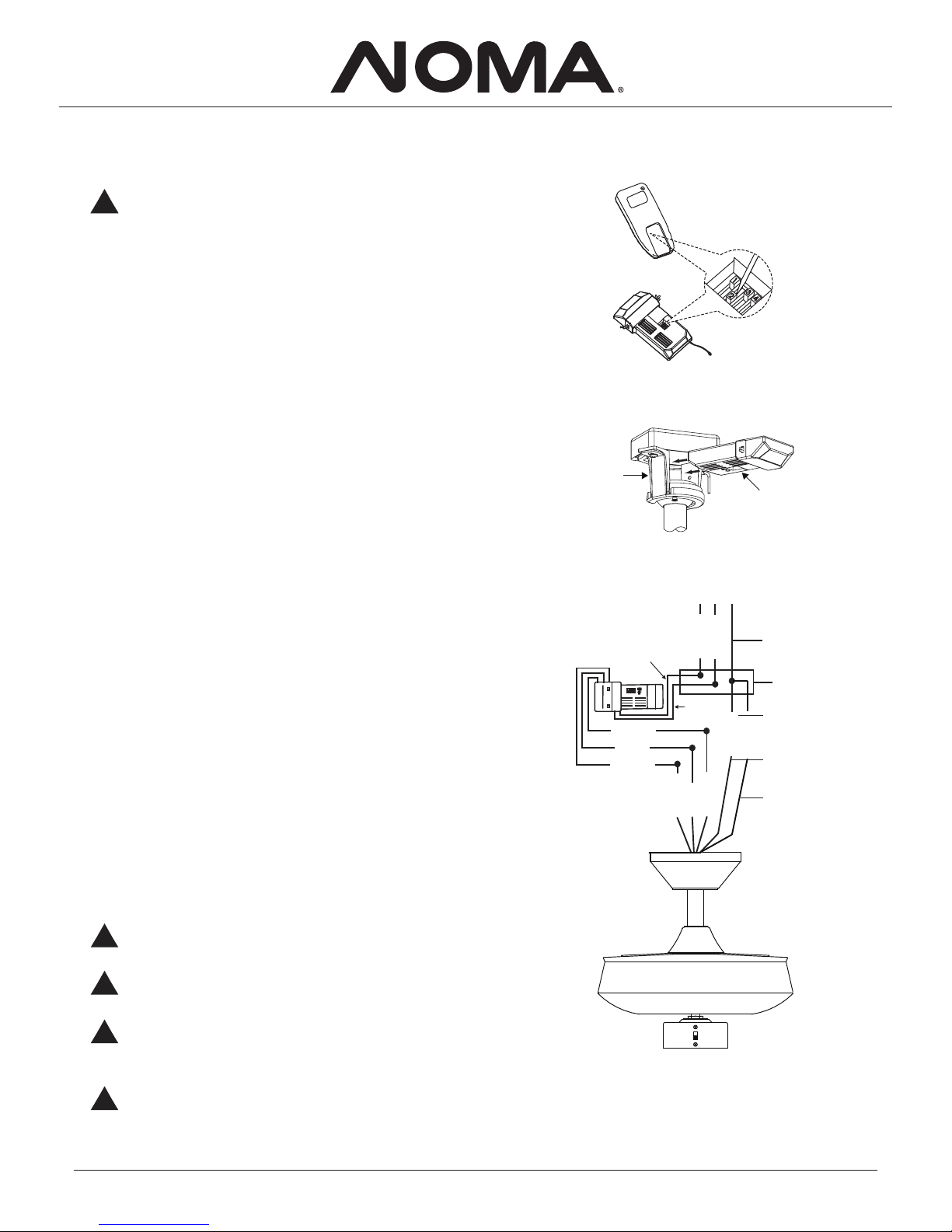
1. This remote control unit is equipped with 16 code combinations to prevent possible interference from or to other remote
units. The frequency switches on your receiver and transmitter
have been preset at the factory. Please check to make sure
the switches on the transmitter and the receiver are set to the
same position. Any combination of settings will operate the fan
as long as the transmitter and receiver are set to the same
position (see Fig. 7).
2. Insert the receiver into the mounting bracket with the flat side
of the receiver facing the ceiling (see Fig. 8).
3. Motor to receiver electrical connections: Connect the black wire
from the fan to the black wire marked "To Motor L" from the
receiver. Connect the white wire from the fan to the white wire
marked "To Motor N" from the receiver. Connect the blue
wire from the fan to the blue wire marked "For Light" from the
receiver. Secure the wire connections with the plastic wireconnecting nuts provided (see Fig. 9).
4. Receiver to house supply wires electrical connections:
Connect the black (hot) wire from the ceiling to the black wire
marked "AC in L" from the receiver. Connect the white
(neutral) wire from the ceiling to the white wire marked "AC
in N" from the receiver. Secure the wire connections with the
plastic wire-connecting nuts provided (see Fig. 9).
5. If your outlet box has a ground wire (green or bare copper)
connect it to the fan ground wires; otherwise connect the
hanging bracket ground wire to the mounting bracket. Secure
the wire connection with a plastic wire-connecting nut provided.
After connecting the wires spread them apart so that the green and
white wires are on one side of the outlet box and black and blue
wires are on the other side. Carefully tuck the wire connections up into the outlet box (see Fig. 9).
Making the Electrical Connections
Fig. 7
Fig. 8
Fig. 9
Warning: To avoid possible electric shock, be sure
electricity is turned off at the main fuse box before
wiring.
!
Note: Fan must be installed at a maximum distance of 20' (6.1 m)
from the transmitting unit for proper signal transmission
between the transmitting unit and the fan's receiving unit.
!
Caution: Do not use wall switch with dimmer function.
!
!
!
Warning: Check to see that all connections are tight, including ground, and that no bare wire is visible at the wire nuts,
except for the ground wire.
Warning: Electrical diagrams are for reference only.
Optional use of any light kit must be UL listed and marked
as suitable for use with this fan.
Frequency switch
Receiver
Ceiling
mounting
bracket
SUPPLY CIRCUIT
WHITE
WHITE
BLACK
BLACK
BLUE
Ground
conductor
Outlet box
Green
ground
lead
GREEN
GREEN
Ground from
downrod
Ground from
mounting bracket
BLACK
BLACK
BLUE
WHITE
WHITE
7
Fig. 10
Fig. 11
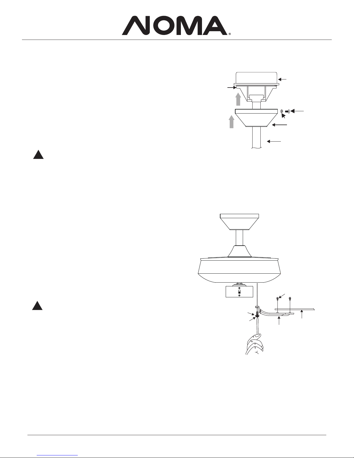
Outlet box
Mounting
bracket
Canopy
Canopy
bottom cover
1. Tuck connections neatly into ceiling outlet box.
3. Firmly tighten the two mounting screws.
4. Install the remaining two mounting screws into the holes
in the canopy and tighten firmly.
2. Slide the canopy up to the mounting bracket, align the
locking slots of the ceiling canopy with the two screws
in the mounting bracket. Push up to engage the slots, and
turn clockwise to lock the canopy in place.
Finishing the Fan Installation
Attaching the Fan Blades
Warning: Make sure the tab on the hanging bracket
properly sits in the groove in the hanger ball before
attaching the canopy to the bracket by turning the
housing until it drops into place.
!
1. Attach the blade to the blade arm using the blade screws
as shown in Fig. 11.
2. Tighten each screw. Make sure the blade is straight.
3. Fasten one blade assembly to the motor using the two blade arm
screws and spring washers supplied (see Fig. 11).
4. Repeat this process with the other blades
Warning: To reduce the risk of personal injury, do not
bend the blade arms while installing, balancing the
blades, or cleaning the fan. Do not insert foreign objects
between rotating fan blades.
!
Canopy
mounting
screw
washer
Blade arm screw
Spring washer
Blade
Blade arm
Blade screw
 Loading...