

NOMA 52-4477-8 Installation And Operating Instructions Manual
Carriage Light with
Motion-activated Sensor
Tail Assembly
Coach Light
FEATURES
• Automatically comes on when motion is detected.
• Automatically turns light off.
• Photocell keeps the light off during daylight
hours.
is package includes:
• Mounting screws and wire connectors
REQUIREMENTS
• e Light Control requires 120 volts AC.
• If you want to use Manual Mode, the control
must be wired through a switch.
• Some electrical codes require installation by
a qualified electrician. Please check the codes
in your area.
Model 52-4477-8
Before installation, record the model number listed inside the xture. Attach receipt
in case of possible warranty issues.
Model Number:
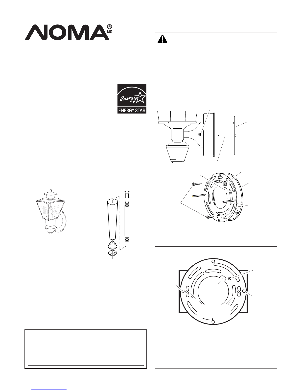
Wire
Path
Junction Box
Screws
Fixture
Screw
Horizontal Junction Boxes Only:
Remove ground screw and 2 fixture screws from
the mounting plate. Flip plate over. Reinsert
ground screw. Insert the 2 fixture screws in the
holes near the junction box screws holes. Wire
path must be located as shown above.
Ground
Screw
Wire Path
Ground Screw
Mounting
Plate
Fixture
Screw
INSTALLATION
Decorative Nut
Mounting Screw
Bracket
Mounting
Screw
Mounting
Plate
Junction
Box
598-1285-00
Note: We recommend having an assistant help hold
the lantern assembly during the wiring process.
For best performance, mount the fixture about 6
feet (1.8 m) above the ground.
1. Remove two decorative nuts.
2. Remove mounting plate.
3. Tighten mounting screws finger tight.
4. Attach mounting plate to junction box.
WARNING: Turn power o at circuit
breaker or fuse.
Installation and
Operating Instructions
2
598-1285-00
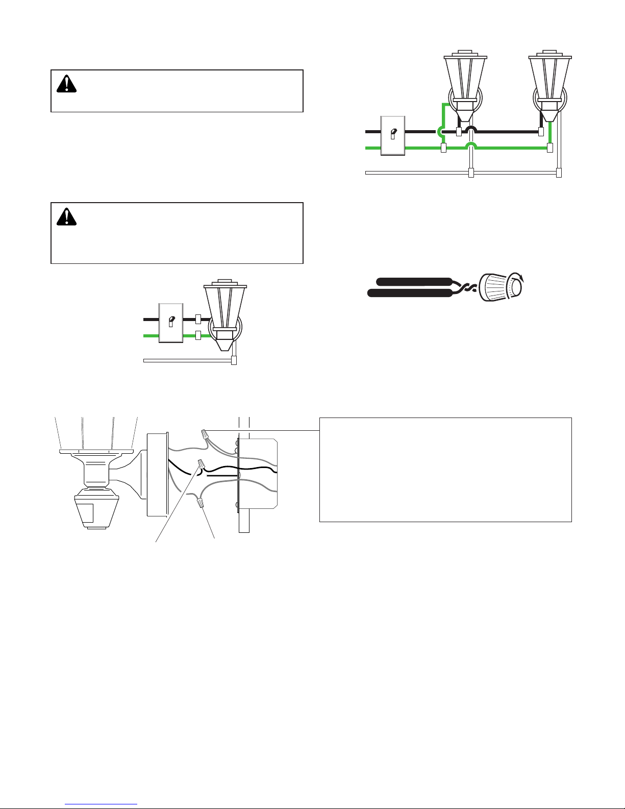
One Motion Light
Black to black
White to white
Two Motion Lights
Recommended Grounding Method
Use a green ground “pigtail” (not provided) and
twist one end together with the bare fixture wire
and the box ground wire. Secure with a wire
connector. Secure the other end of the “pigtail”
with the GND screw on the mounting plate.
Black
White
Green
or Bare
Black
White
Green or Bare
WIRING
CAUTION: DO NOT connect the RED wire
unless you want to control other lights from
the motion sensor (see Optional Wiring).
Note: All wiring must be run in accordance with
the Canadian Electrical Code through conduit
or another acceptable means. Contact a quali-
fied electrician if there is any question as to the
suitability of the system.
WARNING: Turn power o at circuit
breaker or fuse.
Connect the fixture wires to the wires in the junc
tion box. Twist the wires together and secure with
wire connectors.
If you have metal junction box, you may not need
the green “pigtail”. If you are unsure about the
grounding method, consult your local building
code.
3
598-1285-00
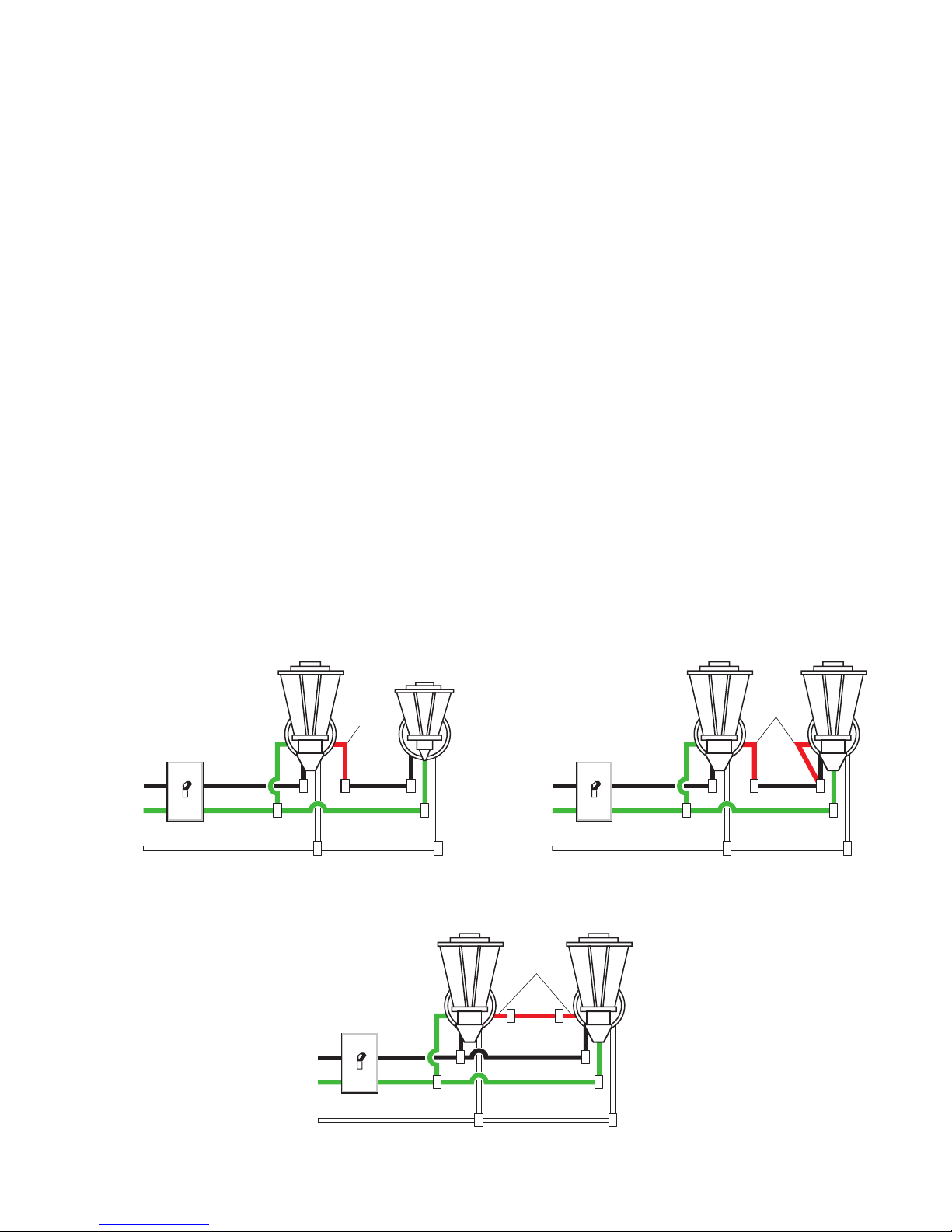
Black
(Standard)
Wiring Diagram 1
White
Master
Wiring Diagram 2
Red
Wiring Diagram 3
Green
or Bare
Slave
OPTIONAL WIRING
is fixture is provided with a sensor rated for 500 Watts. Since the fixture is only rated 100 Watts, 400
Watts of additional lighting may be controlled by this sensor.
When determining what a fixture is rated for, do not simply look at the rating on the lamp in the
fixture. Look at the marking which specifies the maximum lamp wattage for which the fixture is
suitable.
Once you have selected the fixtures to be connected and determined their maximum ratings, add these
ratings up. For instance, if you have 3 fixtures rated 100 Watts, 150 Watts, and 75 Watts respectively,
you have a total load of 325 Watts.
Wiring Diagram 1 – When wiring to control a standard light xture: Strip the motion sensor’s
red wire and connect to the standard light’s black wire. Connect all white wires together. Total fixture
ratings must not exceed 500 Watts (4.1 A).
Wiring Diagram 2 – When wiring to control another motion sensing light xture (Master /
Slave): Strip the red wire in both light fixtures. Connect the red wire of the controlling (master)
fixture to the red and black wires of the controlled (slave) fixture. Connect all white wires together.
Total fixture ratings must not exceed 500 Watts (4.1 A).
Wiring Diagram 3 – When wiring so either motion light turns on the both motion lights
(Master / Master): Strip the red wire in both light fixtures. Connect the red wire of one fixture to
the red wire of the second fixture. Note: In most installations, an additional wire (same gage as existing house wire) will have to be installed in the house to connect the two fixtures as master / master.
Connect all white wires together and all black wires together. Total fixture ratings must not exceed
500 Watts (4.1 A).
Black
White
Green
or Bare
Red
Master Master
Red
Black
White
Green
or Bare
4
598-1285-00
TEST 1 5 10 MIN
ON-TIME
LO - M - HI
SENSITIVITY
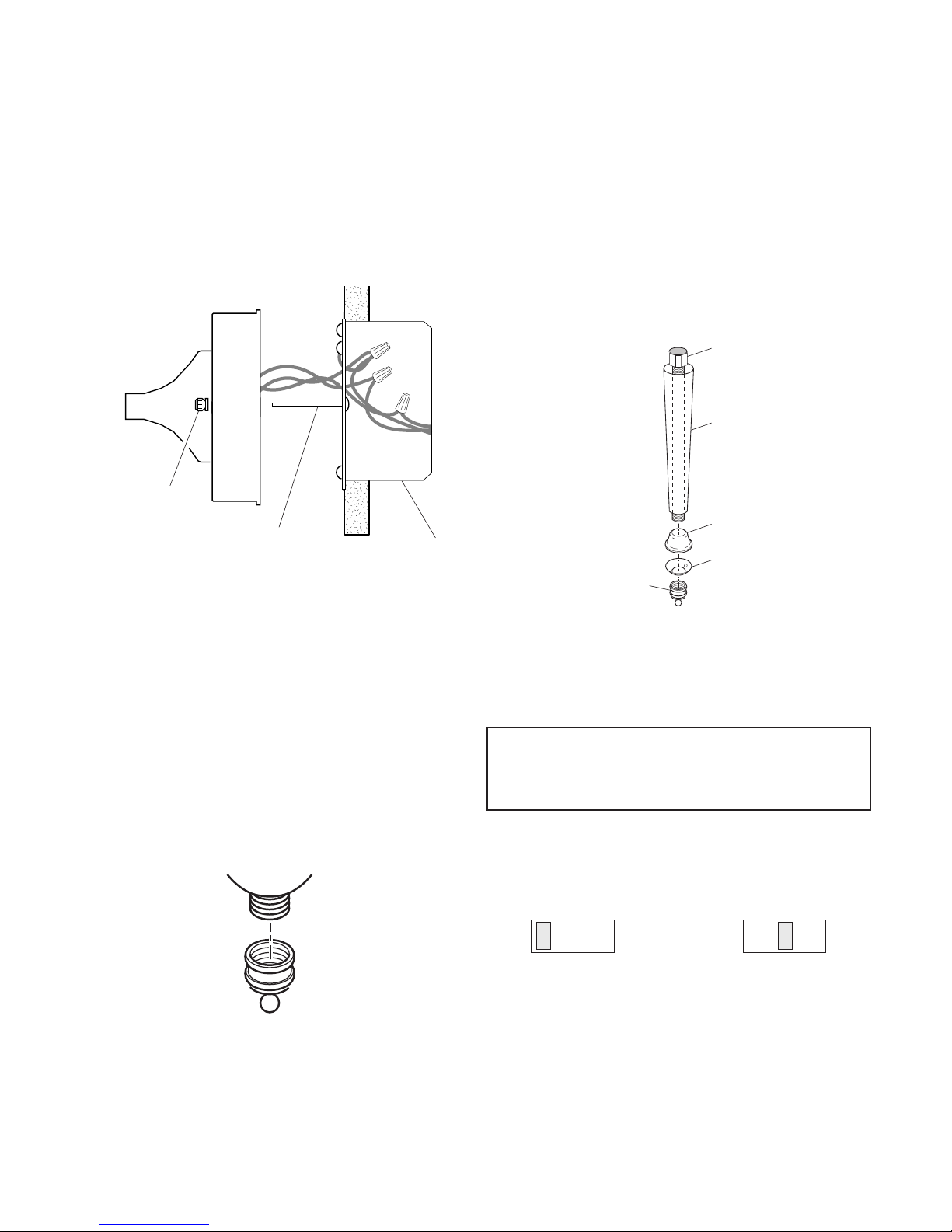
Junction Box
Optional Assembly
If so equipped, you may install the decorative tail
as shown below.
1. Screw hex nut onto bottom of fixture.
2. Screw extension bar into hex nut.
3. Slide tail piece and top trim piece onto exten-
sion bar.
4. Slide bottom trim piece (with drain hole) onto
extension bar.
5. Install the decorative nut onto extension bar.
Hex Nut
FINAL ASSEMBLY
1. Push the wires into the junction box. Make
sure the wires from the fixture go through the
wire path, and no wires get pinched.
2.
Slide the fixture assembly onto the mounting
screws. Tighten decorative nuts removed in step
1 of Installation section securely against fixture
base.
Mounting Screw
Decorative Nut
3. Install one medium base light bulb (100 Watt
maximum).
4. If applicable, place top cover onto fixture and
attach using the two decorative nuts (included).
Hand tighten only.
5. After completing the tests on page 4, caulk
around fixture base with silicone weather
sealant.
6. If you will not be installing the optional tail
assembly, install the decorative nut onto the
bottom of the fixture now.
Tail Piece
Trim (top)
Trim (bottom with
hole)
Decorative Nut
TESTING AND ADJUSTMENTS
1. Turn on the circuit breaker and light
switch.
Note: Sensor has a 1 1/2 minute warm up period
before it will detect motion. When first turned
on wait 1 1/2 minutes.
2. Set:
ON-TIME switch to TEST
SENSITIVITY dial to Midway
5
598-1285-00
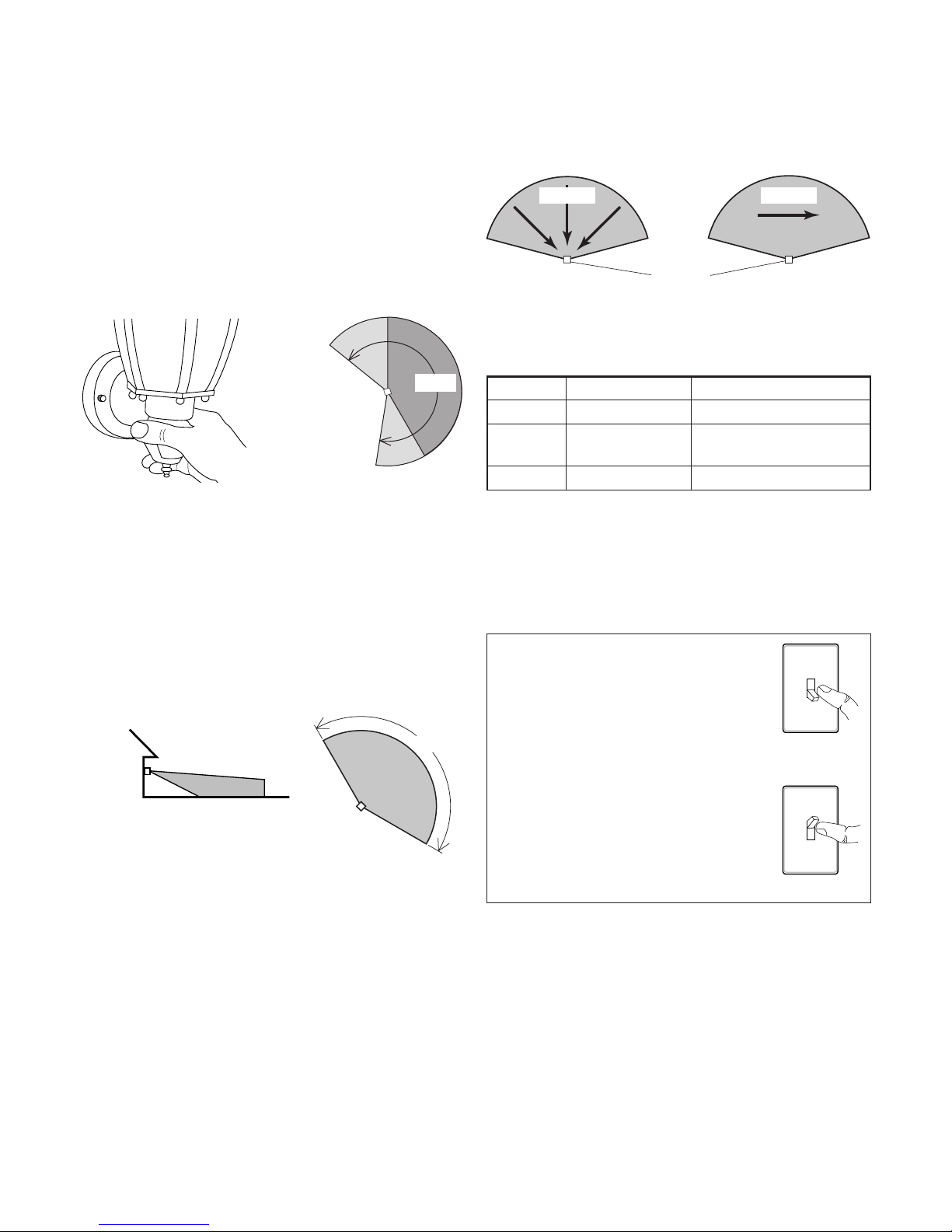
30 ft.
(9.1 m)
6 ft.
(1.8 m)
150°
3.
Walk through the coverage area noting where
you are when the lights turn on. In TEST mode,
light will stay on for 5 seconds after sensing
motion and then turn off.
4.
Move the sensor head left or right to change
the coverage area. Note: Grasp the sensor only
as shown and turn the entire sensor. Any other
method may damage the sensor. Do not
force it past the stops.
Maximum Range Maximum
Coverage Angle*
(Top View)
Note: When first turned on wait about 1 1/2 minutes
for the circuitry to calibrate.
* resets to Auto Mode at dawn.
Least Sensitive Most Sensitive
e sensor is less sensitive to motion directly
towards it and more sensitive to motion across
coverage area.
Sensor
Motion
OPERATION
Mode: On-Time Works: Day Night
Test
5 Seconds
x x
Auto
1, 5, or 10
Minutes
x
Manual
To Dawn*
x
... back on.
1 Second
OFF then...
Manual mode only works at
night because daylight returns
the sensor to AUTO.
Flip the light switch off for one
second then back on to toggle
between AUTO and MANUAL
MODE.
Manual mode works only with
the ON-TIME switch in the 1,
5, or 10 position.
MANUAL MODE
240°
Sensor
Aiming
Adjustment
Angle
5. Adjust the SENSITIVITY to increase or
decrease the range as needed. Too much sensitivity may cause false triggering due to heat
sources in the coverage area (see
Adjustment of
Coverage Area or Troubleshooting
section).
6. Set the amount of ON-TIME you want the
light to stay on after motion is detected (1, 5,
or 10 minutes).
Motion
 Loading...