

Page 1
5+1+1 Day Programmable Thermostat
with outdoor temperature transmitter
Model No:
52-2546-6
Page 2

Features:
5+1+1 day prog ramming (wee kdays +Sat+Sun) with 4 prog rams per day
Ideal for central heating f urna ce system s
Interf aces with hea ting /air conditioning system s for autom ati c tem perature control
Separate Heat/Co ol prog rams with buil t-in protection for t he ai r-con diti oner compressor
Interf aces with hum idifier f or autom atic hum idity con trol
Temperature display and prog ram ming in Ce lsius or Fahrenh eit
Precisi on temperature con trol, set in half de grees
Displays outdoor temperature from a remote trans mit ter
Selectab le cycle rates for more energy eff ici ent hea ting
Usage monitor - tr acks accu mulated heating “ON” time
12 or 24 hou r clock display
LCD display with bac klight
Furnace fil ter chan ge reminde r
Installation kit includes:
- 3 AA batteries
- Mounting hardware
SPECIFICATIONS
Rating: 24 V mil livolt hea ting system s
* NOT COMPATIBLE WITH ANY
HIGH VOLTAGE CIRCUIT
OR BASEBOARD HEATER
Page 3

Table of Contents
Installation Guide. . . . . . . . . . . . . . . . . . . . . . . . . . . . . . . . . . . . . . . . . . . . . . . . . . 1
System Testing. . . . . . . . . . . . . . . . . . . . . . . . . . . . . . . . . . . . . . . . . . . . . . . . . . . . . . . . . . . . . . . . . . . . . . . . . . . . . 4
Fan Operation Jumper HE/HG . . . . . . . . . . . . . . . . . . . . . . . . . . . . . . . . . . . . . . . . . . . . . . . . . . . . . . . . . . . . . . . . 6
Wiring . . . . . . . . . . . . . . . . . . . . . . . . . . . . . . . . . . . . . . . . . . . . . . . . . . . . . . . . . . . . . . . . . . . . . . . . . . . . . . . . . . . . 10
Operation and programming guide . . . . . . . . . . . . . . . . . . . . . . . . . . . . . . . . . . . 16
Unit Diagram . . . . . . . . . . . . . . . . . . . . . . . . . . . . . . . . . . . . . . . . . . . . . . . . . . . . . . . . . . . . . . . . . . . . . . . . . . . . . . 17
Full LCD Display . . . . . . . . . . . . . . . . . . . . . . . . . . . . . . . . . . . . . . . . . . . . . . . . . . . . . . . . . . . . . . . . . . . . . . . . . . . 18
Set ºC or ºF . . . . . . . . . . . . . . . . . . . . . . . . . . . . . . . . . . . . . . . . . . . . . . . . . . . . . . . . . . . . . . . . . . . . . . . . . . . . . . . 20
Set Clock . . . . . . . . . . . . . . . . . . . . . . . . . . . . . . . . . . . . . . . . . . . . . . . . . . . . . . . . . . . . . . . . . . . . . . . . . . . . . . . . . 21
Program Heating / Cooling. . . . . . . . . . . . . . . . . . . . . . . . . . . . . . . . . . . . . . . . . . . . . . . . . . . . . . . . . . . . . . . . 22
Temporary Override Function . . . . . . . . . . . . . . . . . . . . . . . . . . . . . . . . . . . . . . . . . . . . . . . . . . . . . . . . . . . . . . . . . 26
Hold Function. . . . . . . . . . . . . . . . . . . . . . . . . . . . . . . . . . . . . . . . . . . . . . . . . . . . . . . . . . . . . . . . . . . . . . . . . . . . . . 26
Humidity Display / Control . . . . . . . . . . . . . . . . . . . . . . . . . . . . . . . . . . . . . . . . . . . . . . . . . . . . . . . . . . . . . . . . . . . . 27
HEAT / COOL switch / Fan Ventilation. . . . . . . . . . . . . . . . . . . . . . . . . . . . . . . . . . . . . . . . . . . . . . . . . . . . . . . . . . . 28
Pre-comfort Recovery . . . . . . . . . . . . . . . . . . . . . . . . . . . . . . . . . . . . . . . . . . . . . . . . . . . . . . . . . . . . . . . . . . . . . . . 29
Usage Monitor . . . . . . . . . . . . . . . . . . . . . . . . . . . . . . . . . . . . . . . . . . . . . . . . . . . . . . . . . . . . . . . . . . . . . . . . . . . . . 29
Filter Change . . . . . . . . . . . . . . . . . . . . . . . . . . . . . . . . . . . . . . . . . . . . . . . . . . . . . . . . . . . . . . . . . . . . . . . . . . . . . . 29
Battery Changing . . . . . . . . . . . . . . . . . . . . . . . . . . . . . . . . . . . . . . . . . . . . . . . . . . . . . . . . . . . . . . . . . . . . . . . . . . . 30
Backlight . . . . . . . . . . . . . . . . . . . . . . . . . . . . . . . . . . . . . . . . . . . . . . . . . . . . . . . . . . . . . . . . . . . . . . . . . . . . . . . . . 30
Outdoor temperature transmitter . . . . . . . . . . . . . . . . . . . . . . . . . . . . . . . . . . . . . . . . . . . . . . . . . . . . . . . . . . . . . . . 31
Option Section . . . . . . . . . . . . . . . . . . . . . . . . . . . . . . . . . . . . . . . . . . . . . . . . . . . . . . . . . . . . . . . . . . . . . . . . . . . . 35
Specifications. . . . . . . . . . . . . . . . . . . . . . . . . . . . . . . . . . . . . . . . . . . . . . . . . . . . . . . . . . . . . . . . . . . . . . . . . . . . . . 38
Troubleshooting. . . . . . . . . . . . . . . . . . . . . . . . . . . . . . . . . . . . . . . . . . . . . . . . . . . . . . . . . . . . . . . . . . . . . . . . . . . . 38
Page 4
Installation
Guide
1
Page 5

Installation Guide
Introduction
This thermostat can replace common residential thermostats and it is designed for use with
most central heating and air conditioning systems that use low voltage control. Please see
the compatibility chart on the next page for more details.
3 “AA” size batteries required (included)
Built-in protection timing for the air conditioner compressor
Warning
It is recommended to consult a wiring professional to ensure the safe installation of your thermostat.
The only way to guarantee wiring safety is to have a qualified professional on site. Since each
residence may be wired differently, UPM’s customer service line cannot offer any wiring advice.
UPM assumes no responsibility for customer errors in installation or wiring or any resulting damages.
* NOT COMPATIBLE WITH ANY HIGH VOLTAGE 120/240 VOLT CIRCUIT.
2
Page 6

Compatibility
Generally, equipment with low voltage control is compatible with the Heating/Cooling Programmable
Thermostats.
System Type
Gas - Standing Pilot
Gas - Electronic Ignition
Gas - Fire Boiler
Gas - Millivolt System
Oil - Fire Boiler
Oil - Fire Furnace
Electric Furnace
Electric Air Conditioner
Baseboard Electric Heater (120/240V)
Heat Pump/Single-Stage (some models)
Heat Pump/Multi-Stage equipment
Compatible with Thermostat
Yes
Yes
Some models
Yes
Some models
Yes
Yes
Yes
No
No
No
* NOT COMPATIBLE WITH ANY HIGH VOLTAGE 120/240 VOLT CIRCUIT.
3
Page 7

System Testing
It is very important that you fully test your heating, cooling and humidity equipment, both
before and after installing your new thermostat. The first test will determine if the equipment is
operational at the beginning of the process; the second test will ensure that the wiring and
installation were completed correctly.
It may be tempting to only test the heating equipment if you install the thermostat in the winter, or to
only test the air conditioning and humidifier if you install it in the summer. However it is highly
recommended to test all equipment at the time of installation.
SYSTEM TESTS: (BEFORE AND AFTER INSTALLATION)
- Make sure power is on for all heating and cooling appliances.
- Ensure the thermostat is switched to HEAT mode.
- Raise the temperature setting to see if furnace will activate. (May take up to 10 minutes)
- Ensure the thermostat is switched to COOL mode.
- Reduce the temperature setting to see if the air conditioner will activate.
(Note: Do not activate air conditioning if the temperature is below 10°C (50°F)
as this may damage the outdoor compressor.)
- Ensure the thermostat is switched to HEAT mode.
- Increase you humidity setting to see if the humidifier will activate.
- For heating systems with more than three wires, put the fan in the ON position.
(The fan should come on immediately.)
4
Page 8
IMPORTANT - Get ting Started
C
%
C
C
%
C
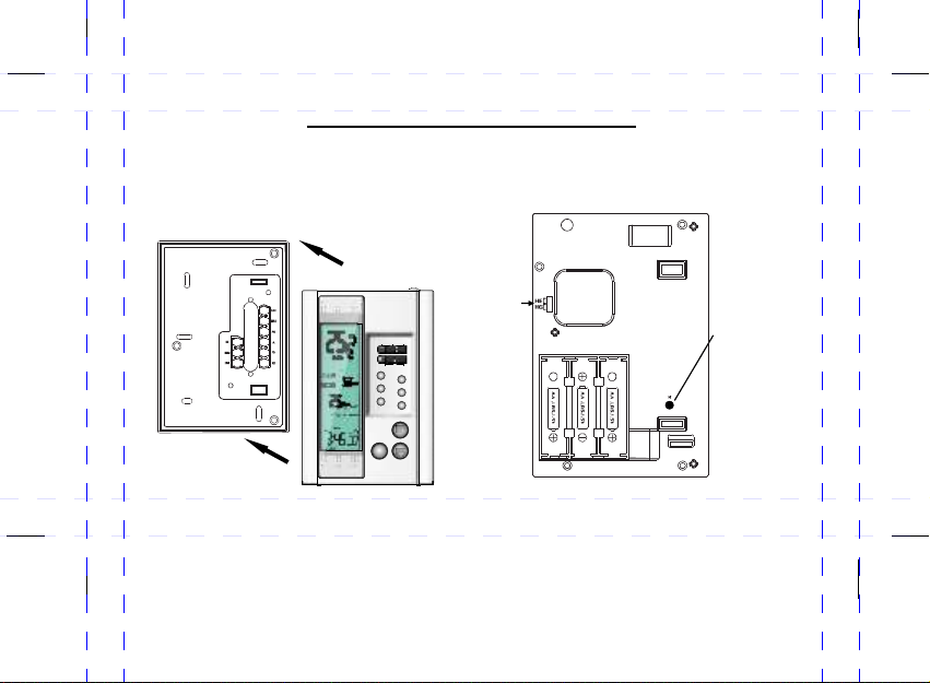
Remo ve t he rm ostat backp la te a nd install 3 “AA” siz e ba tt eries (incl ud ed ).
** **
Ensu re t he b at teries are in st al led in the corr ec t di re ction for pol ar it y.
Ensu re t he H E / HG J UMPER is in the c or re ct position ( se e ne xt p age).
Remove Backplate
Front
HE
HG
JUMPER
COOLOFFHEAT
ON AUTO
SET
HOLD
PROG
USAGE
AHEAD
BACK
Back
Reset Button:
to restore
default settings
Install 3 AA Batteries
5
Page 9
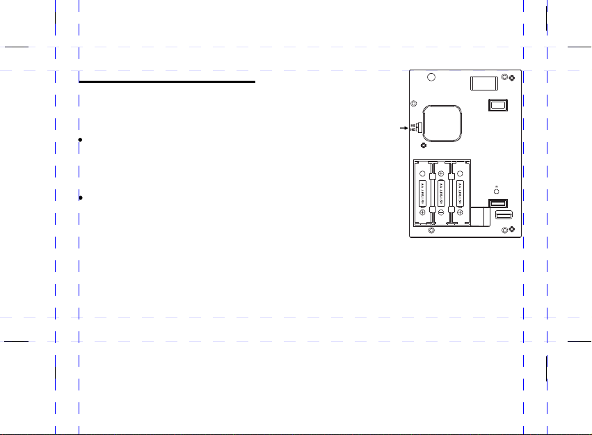
Fan Operation Jumper HE/HG
Depending on your home’s heating system you may need to
change the jumper setting for the fan operation. The jumper
is located on the back of the thermostat.
HG - Use this setting for gas and oil-fire powered furnaces.
This setting allows the fan operation to be controlled
by the heating system; not the thermostat. This is the
correct setting for most systems.
HE - Use this setting for electric powered furnaces. With this
setting the thermostat will turn on the fan immediately with the
heating system.
The jumper is pre-installed in the HG position as a factory default.
So there is no need to change the jumper if this setting is correct.
To change the jumper setting to the HE position, pull out the small black
rectangular block and align it to the new position and push it in fully.
JUMPER
6
HE
HG
Back
Page 10

AFTER INSTALLING THE BATTERIES
CELSI US D EFAU LT; Sinc e Ce lsius ( °C ) is th e de fa ult m od e no acti on i s req ui re d to us e th e
therm os tat i n th is mode .
(°C or °F ) It i s VER Y IM PO RTA NT th at y ou choo se Fa hr enhei t (° F) be fo re y ou be gi n using t he
therm os tat . If y ou p roc ee d to se t th e cl ock a nd p rogra m se tti ng s wi th th e de fault C el siu s( °C )an d
THEN ch an ge to t he Fahr en hei t (° F) set ti ng: the c lo ck, p ro gr ams a nd a ll syst em s ett in gs w ill b e de leted .
(RESE T) I f the d is pl ay do es n ot ap pe ar a fte r in stall in g the b at te rie s, p ress th e re set b ut to n on th e
back of t he u nit .
SEE OPT IO N SEC TI ON: T he t hermo st at ha s a nu mb er of O PT IONS wh ic h the u se r ca n cha ng e.
(NOTE : *A dju st t he se se tt ing s be fo re pr og rammi ng t he th er mo sta t, b ecaus e ch ang in g ce rta in
optio ns w ill e ra se all pr og ram mi ng .)
7
Page 11
Installation
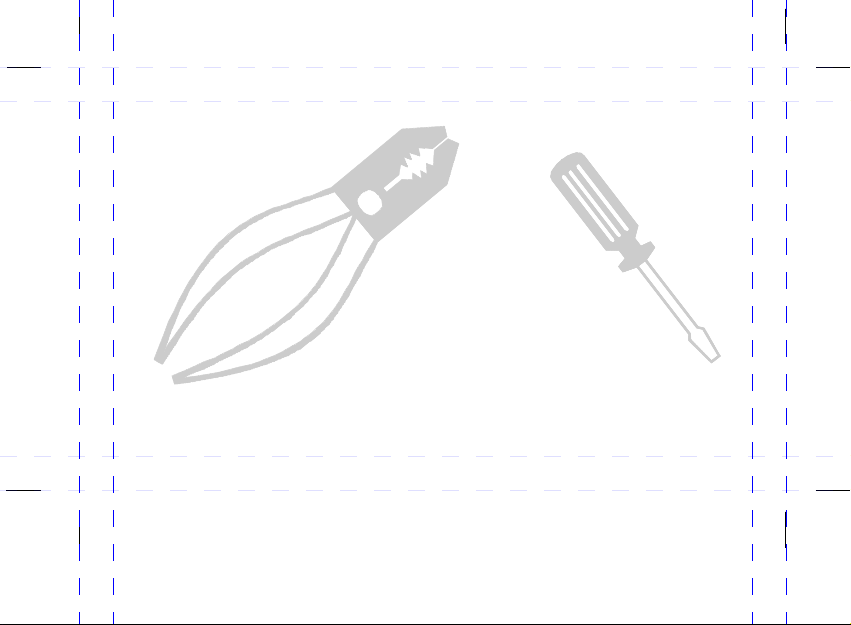
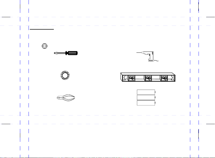
The following tools may be required for installation:
( ) screwdriver
Masking Tape
(To wrap the exposed wires temporarily and to label
the disconnected wires)
Power drill with a 3/16” bit
(If necessary, to drill holes on the wall)
Level
(If necessary, to level the thermostat)
Wire Stripper/Cutter
(If necessary, to strip the wires)
3 “AA” size batteries (included)
-
“AA” SIZE
- +
“AA” SIZE
- +
“AA” SIZE
8
+
Page 12

Choosing location for new thermostat
Thermostat should be mounted:
Approximately 5’ (1.5 m) from floor
Near or in a frequently used room, preferably on an inside partitioning wall
On a section of wall without pipes or duct-work
Thermostat should NOT be mounted:
Near a window, on an outside wall, or next to a door leading outside
Exposed to direct light or heat from a lamp, sun, fireplace, or other temperature-radiating objects
which may cause false readings
Near or in direct airflow from heat registers and air conditioners
Near concealed pipes and chimneys
In areas with poor air circulation, such as behind a door or in an alcove
Note: Do not operate the cooling system when outside temperature is below 10°C (50°F) to avoid
damaging the compressor.
9
Page 13

Replacing old thermostat
Test the system to make sure that your heating and cooling systems are working properly
before installation. If either does not work, contact a heating/air conditioning service person
to fix the problem before installation.
TURN OFF POWER to system at the furnace, or at the fuse/circuit breaker panel.
Carefully unpack your new thermostat and mounting plate; save package of screws, instructions and
receipt. Remove cover from old thermostat. If it does not snap off when pulled firmly from the bottom,
check for a screw used to secure the cover. Loosen screws holding thermostat to the wall and lift
away the thermostat.
Wiring
NOTE: WIRING COLORS ARE NOT ALWAYS STANDARDIZED, SO IT IS VERY IMPORTANT TO
LABEL ALL WIRES ACCORDING THE LETTER DESIGNATION ON YOUR OLD THERMOSTAT.
(The wires are usually designated 'W', 'Y', 'G', 'RH', 'RC', 'W' ,'B', ‘O' or humidistat wires.)
Disconnect wires from old thermostat or sub-base. As you disconnect each wire, use masking tape
to label it with the old terminal designation.
Take care not to let the wires fall back into the wall or let the ends of the wires touch one another.
If there is an extra wire that is not connected to your old thermostat, then you won't need to connect
it to the new thermostat.
10
Page 14
Connecting the wires to the terminals
Connect the previously labeled wires to the corresponding
terminals, matching the designations. Use a screwdriver
to loosen the terminal, wrap the wires around the terminal,
then tighten to securely fasten the wires. Make sure the
wires do not touch or short-circuit with other terminals.
After aligning the wires to the correct terminal push
excess wires back into the wall hole.
Depending on your heating/cooling equipment, you
may need to connect 2 to 7 wires to the thermostat.
If you have two ‘R’ wires, then connect each wire to
its corresponding terminal and remove the JUMPER
between the RC and RH terminals.
If you are unsure of the connections please consult
a certified electrician for the safe installation of your
thermostat.
11
e.g. (H 1, H2, W, Y, G, B, O, Rc, Rh )
Termin als
for w iri ng
Wires
fro m
the w all
Wire La bel s
Bac k Cover
Page 15

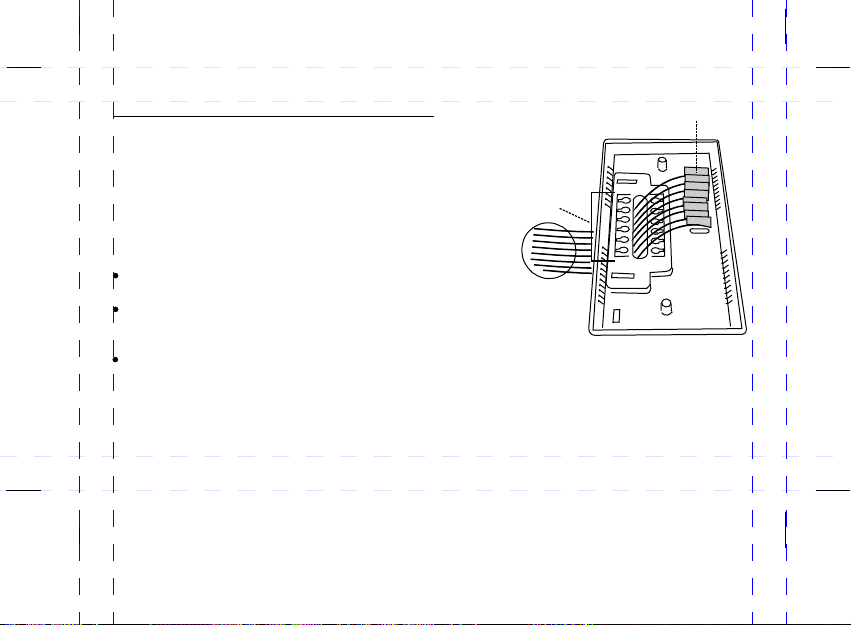
Mounting the thermostat back cover
The back cover should be mounted vertically with the
terminals to the left.
Thread the existing wiring through the big center hole
from the back and set the back cover vertically on the
wall.
Select the mounting holes and mark the locations with
a pencil. If necessary, use a level to make sure the
thermostat is leveled.
Remove the back cover from the wall and drill two
3/16” holes in the marked screw positions. Insert the wall
anchors into the holes completely. If necessary, use a
hammer to tap-in lightly.
Mount the back cover to the wall with the screws.
Attach the thermostat body to the back cover (that is
already mounted on the wall) by carefully aligning the two
pieces and pressing firmly until they snap together.
12
Termin als
for w iri ng
Bac k cov er
LEVEL
Mark
the screw
locations
with a pencil
Page 16

Wiring Diagrams
2-WIRE HEATING
G
Y
H2
H1
3-WIRE HEATING
H2
H1
B
W
(OPTIONAL)
JUMPER
Rh
O
Rc
G
Y
B
W
Rh
O
Rc
Wiring Key
Regular Wiring
G - Fan output
Y - Cool output
H1 / H2 - Humidifier control
Rc - Common for Cooling and Fan
Rh - Common for Heating
W - Heat output
2 Wire Heating
Rc / Rh - Common
(Rc and Rh jumper is optional)
3 Wire Heating
Rc / Rh - Common (Rc and Rh
must be connected with jumper)
13
Page 17

Wiring Diagrams
4-WIRE HEATING/COOLING
H1
5-WIRE HEATING/COOLING
H1
G
Y
H2
H2
B
W
O
Rh
Rc
G
Y
B
W
Rc
Rh
O
Wiring Key
Regular Wiring
G - Fan output
Y - Cool output
H1 / H2 - Humidifier control
Rc - Common for Cooling and Fan
Rh - Common for Heating
W - Heat output
4 Wire Heating
Rc / Rh - Common (Rc and Rh
must be connected with jumper)
5 Wire Heating
2 separate transformers (Heat / Cool)
Rc / Rh - Common (wire separately,
jumper must not be installed)
14
Page 18

Humidifier Wiring
To wire a humidifier, the 2 wires connecting the original humidistat need to be
connected to the 2 terminals marked 'H1' and 'H2' on the thermostat.
The original humidistat should be removed or set to 'OFF' position.
Note: The 2 humidifier control terminals 'H1' and 'H2' are electrically isolated from the
Heat/Cool terminals.
Note: H1 and H2 terminals are non polarized and there is no function difference between H1 and H2.
H1
H2
W
G
Y
O
Rh
B
Rc
Humidistat should be
OFF or disconnected
15
Page 19

Operation and
Programming Guide
16
Page 20

C
%
C
C
%
C
Unit Diagrams: Back / Front Buttons
INSTALL
3 BATTERIES
RESET
SET
PROG
AHEAD
ON AUTO
LCD DISPLAY
HEAT/COOL SWITCH
COOLOFFHEAT
FAN SWITCH
SET CLOCK
HOLD
HOLD
USAGE
BACK
PROG (Program)
USAGE
BACK
AHEAD
UP
DOWN
OUTDOOR / DISPLAY
17
Page 21

Full Display:
includes all icons,
for reference only.
HOLD MODE
OVERRIDE MO DE
FILTER CHANGE
AIR CONDITI ONIN G “ON”
HUMIDITY “O N”
HEATING“ON ”
CURRENT TEM PERATURE
CELSIUS OR FAHRENHEIT
SYSTEM
MODE
TEMPERATUR E SETTING
OUTDOOR TEM PERATURE
PROGRAM PER IODS
USAGE
AM/PM
HUMIDITY DI SPLAY
LOW BATT ERY
OPTION MODE
PROGRAM MOD E
HUMIDITY MO DE
“SET” PROGR AM
“SET” CLOCK
TIME
WEEKDAYS
18
Page 22

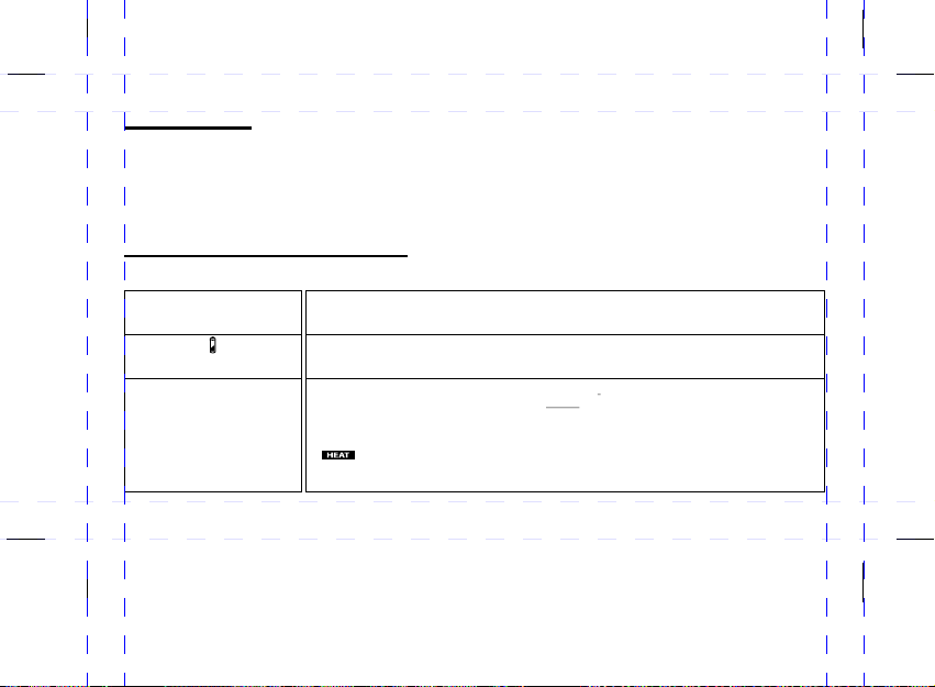
Symbol Key:
These symbols appear to indicate the following:
COOLING - the air conditioning system is in use.
HEATING - the furnace or heating system is in use.
HUMIDITY - the humidifier is in use.
FILTER CHANGE - the furnace filter should be changed.
BATTERY - the batteries are low and need to be replaced.
19
Page 23

IMPORTANT - Get ting Started
** **
CELS IU S DE FAU LT: Since Cel si us ( °C) is the defa ul t mo de n o action
is req ui re d to u se the thermo st at i n th is mode.
The( °C o r °F ) se tting is a one ti me o nl y setting which m us t be d one just afte r
the ba tt er ie s are install ed . It i s VE RY IMPORTA NT that you choos e Fahren he it
(°F) a t th is t im e, because th is s et ti ng CANNOT be ch an ge d afterward s un le ss
you pr es s th e re set button. H ow ev er, press in g re se t will delete a ll t he s ettings
for th e cl oc k, t emperatur e pr og ra ms and option s.
Select ºC o r ºF (Celsiu s or Fahrenh eit)
1
Insert the 3 batt er ie s in t he c or rect direction for po la ri ty ( se e di ag ram pg5).
(The temperat ur e mo de w il l fl as h for 3 seconds, imme di at el y af te r th e
batteries are i ns ta ll ed o r af te r the RESET button is p re ss ed .)
2
Press UP or DOWN to s el ec t Fahrenheit (° F) m od e.
After 3 seconds t he f la sh in g wi ll s top, the temperat ur e mo de s et ti ng i s now permanent.
20
Page 24

SET CLOCK
AM/PM MODE
TIME
WEEKDAY
Choose 12 o r 24 hour cloc k
1
Press and h ol d th e SE T button for 3 se co nd s.
(The OPTI ON s ym bo l will appear a nd 1 2h r wi ll f lash)
2
Press UP or D OW N to t og gle between 1 2h r of 2 4h r di splay.
(Wa it 1 5 se conds for nor ma l di sp la y to return)
(*S ee OPTI ON Sect ion for mor e de tai ls )
Note: 1 2 ho ur mode i s th e defau lt
so no a ction i s requi red to us e the
the rmost at in thi s mode.
Set Time and Weekday
1
Press the S ET b ut to n to s ta rt t he time setting.
(The cloc k nu mb er s and SET symbols wil l be gi n to f la sh)
2
Press AHEAD or BA CK t o sc ro ll t o current hou r an d mi nu te.
3
Press the S ET b ut to n ag ai n
4
Press AHEAD or BA CK t o sc ro ll t o current wee kd ay.
5
Press the S ET b ut to n ag ai n to e xit.
21
Page 25

Program Heating
This thermostat is equipped with 5+1+1 DAY PROGRAMMING. Weekdays + Saturday + Sunday
programming with 4 settings per day. This thermostat is pre-programmed for your convenience or you
can set your own programs as desired.
temperature settings and start times throughout the day.
P1: MORNING
P2: DAY
P3: EVENING
P4: NIGHT
This is typically the morning period, when you may prefer to wake up to a warmer
temperature.
This is usually an energy-savings period, for the time when you are away from home.
The temperature setting can be reduced to minimize energy consumption. If you are not
away from home on a particular day you may override this setting by manually adjusting
the temperature buttons.
This is the period when you typically return home, and would like the house at a
comfortable temperature. Generally, the temperature is set at warmer settings during the
winter and cooler settings during the summer. If you do not often leave the house during
the day, period 1, 2 or 3 can be set at the same temperature for comfort.
This is the period when you would typically be asleep. You may choose to set the
temperature for energy savings or comfort as desired.
The program periods (P1,P2, P3, P4) allow you to set the
22
Page 26

Set Program
The program periods (P1,P2, P3, P4) allow you to set the temperature settings and start times
throughout the day. These are examples of possible temperature settings, the first being the
factory default setting and second a custom setting.
1) DEFAULT / PRE-PRO GRAMM ED TIME A ND TEMPERA TURE SETTIN GS
PER IOD
MORNIN G
DAY
EVENIN G
NIGHT
P TIM E
6:00am 20.5 C ( 69. 0 F) 25.0 C (77.0 F)
P1
8:00am 17 .0 C (62.5 F) 29 .0 C (84.0 F)
P2
5:00pm 21 .0 C (70.0 F) 25 .0 C (77.0 F)
P3
10:00pm 1 7.0 C (62. 5 F) 26.0 C (79. 0 F)
P4
HEAT S ET PO INT
° ° ° °
° ° ° °
° ° ° °
° ° ° °
COO L SET P OIN T
Example 1
This setting is a default and
will activate automatically.
Convenient for people who
are away from home during
the day and wish to
maximize energy savings.
2) CUSTOM / PRE- PROGR AMMED TI ME AND TEMP ERATURE SET TINGS
PER IOD
MORNIN G
DAY
EVENIN G
NIGHT
P TIM E
P1
P2
P3
P4
HEAT S ET PO INT
° ° ° °
7:00am 20.5 C ( 69. 0 F) 25 .0 C (77.0 F)
8:00am 20 .5 C (69.0 F) 29 .0 C (84.0 F)
5:00pm 20 .5 C (69.0 F) 25 .0 C (77.0 F)
11:00pm 1 7.0 C (62. 5 F) 26.0 C (79. 0 F)
° ° ° °
° ° ° °
° ° ° °
COO L SET P OIN T
23
Example 2
This is custom program set
by the user. Convenient for
people who are at home
during the day, and want
the home warm all day, but
want a cooler temperature
at night.
Page 27

Set Heating Program
5+1+1 day programming means that programming
begins with the Monday to Friday settings, then Saturday,
then Sunday. Scroll through the daily Program Periods
in this order P1, P2, P3, P4 to select the start times and
temperature settings for all four daily program periods.
1
Slide the system switch to the HEAT position.
Press the PROG key once. (P1 / SET will appear)
2
(The Monday to Friday icons will display).)
3
Use AHEAD or BACK to select the desired start time for (P1) Period 1.
4
Use UP or DOWN to set the desired temperature for (P1) Period 1.
5
Press PROG again to adjust the next Program Periods P2, P3, P4.
(Repeat the above steps until all four programs are adjusted to your needs.)
6
Press PROG again to program Saturday, adjust Period 1-4 settings.
7
Press PROG again to program Sunday, adjust Period 1-4 settings.
8
After the Sunday program is complete, press PROG again to end program mode.
PM
TU
MO
WETHFR
24
PERIO D
TEMPE RATURE
SETT ING
PROGR AM MODE
“SET” P ROGRAM
PROGR AM
START TI ME
WEEKD AYS
Page 28

Heating Program
Note:
- The
PROG button can also be used to review the period settings.
- To accelerate the setting speed press and hold the AHEAD/BACK or UP/DOWN buttons.
Temperature can be set in increments of 0.5°.
-
- Program time can be set in increments of 10 minutes.
-
Heat and Cool temperature settings must be at least 3 degrees apart.
Cooling Program
1
Slide the system switch to the COOL position.
- Then proceed with steps 2-8 as you would in the heating program.
Note:
Setting the cooling program is exactly the same as setting the heating program,
except that the cooling program will activate the air conditioner while the heating
program activates the furnace.
25
Page 29

Temporary Override
1
Press the UP / DOWN buttons to select the override temperature. (The OVERRIDE symbol will display)
The thermostat will temporarily adjust the room temperature to this new setting, but will return to the regular
program temperature at the beginning of the next scheduled program time. Only the currently active mode
(heat or cool) setting will be changed. The thermostat has an automatic delay function to protect the
heating and cooling system from irregular on/off sequences. Therefore, it is normal to have a several
minute delay before the system activates.
1
Hold
1
Press the UP / DOWN buttons to select the desired temperature.
2
Press the HOLD button. (The HOLD symbol will display)
This function maintains a constant temperature and disables temperature program periods.
Press the HOLD button once to enter the HOLD mode. (HOLD symbol will appear)
(*When HOLD is activated, you may manually adjust the temperature by pressing UP or DOWN.
However all programs will be disabled. If no temperature changes are manually selected, the current
temperature setting will remain the same indefinitely)
To cancel the HOLD function, press the HOLD button again. (HOLD symbol will disappear)
26
Page 30

Humidiy Display
The relative humidity inside your home is displayed with a % sign in the middle of the LCD screen.
Notes:
l The humidifier will automatically turn on if the relative humidity is lower than the humidity setting
l Humidity is set in increments of 5%
l The humidity level can be set from 20% to 70%
l If the humidity reading is LO% it means that the humidity level is below 20%
l If the humidity reading is HI% it means that the humidity level is above 70%
l The humidifier control only functions when thermostat is in HEAT mode
l Humidity is a manual setting which remains constant (it is not pre-programmable like temperature)
Humidy Control
1
Verify the humidifier is correctly wired to the thermostat. (see installation guide or contact an electrician)
2
Ensure HEAT mode is selected. (The humidifier will only activate if thermostat is in HEAT mode)
3
Press the PROG button repeatedly to scroll though all of the 12 programs, ending with P4 on Sunday.
(HUMID SET will appear and the humidity % sign will flash)
4
Press the UP / DOWN buttons now to adjust the humidity setting.
5
Press PROG button again to exit.
*To de-activate the humidifier, scroll DOWN to the lowest humidity setting, until (OFF%) displays.
27
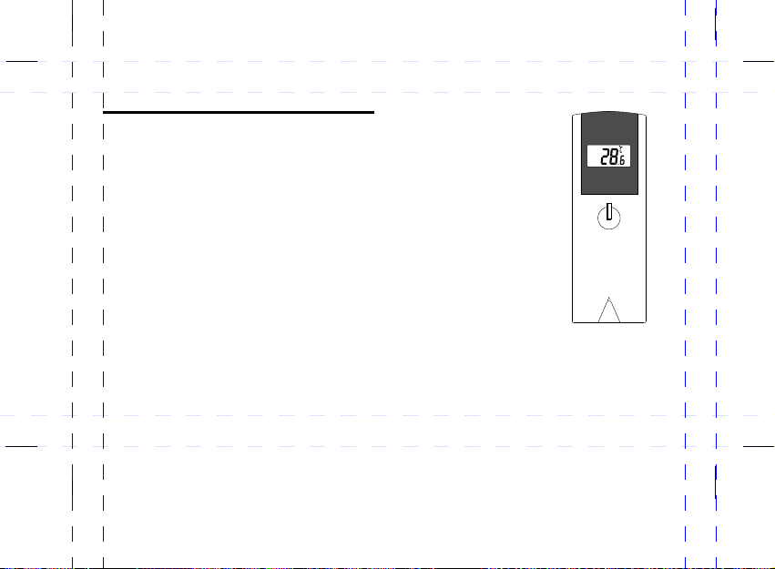
Page 31

HEAT / COOL Switch
Slide the HEAT/OFF/COOL switch to select heating or cooling.
l HEAT - When the thermostat is switched HEAT mode the furnace or heating system will be enabled.
l OFF - If the thermostat is switched to OFF mode, both the heating and cooling systems will be off,
and all programs and settings will be disabled.
l COOL - When the thermostat is switched to COOL mode the air conditioner or cooling system will
be enabled.
When the heating or cooling systems are ON, the following symbols will flash:
The heating system symbol
The cooling system symbol
Fan Control / Ventilation Switch
Slide the ON/AUTO switch to select manual or automatic fan control.
l Select ON for manual control. (the fan will run continuously to improve air ventilation)
l Select AUTO for automatic ventilation. In AUTO mode the heating or cooling system will activate
according to pre-programed temperature settings.
Note:
In heating mode, the fan is controlled by the heating equipment.
In cooling mode, the fan is controlled by the cooling equipment.
28
Page 32

Pre-comfort Recovery
This thermostat is equipped with a ‘Pre-comfort Recovery’ system that will activate the heating or cooling in
advance of the actual set program time so that the room will be at the desired temperature at the start of the
program time.
It is normal for the system to be activated earlier than the actual set program time (up to one hour).
The Pre-comfort Recovery can be disabled if desired. (See "Option Section”)
Usage Monitor
The thermostat tracks the total number of hours the heating and cooling system is operating.
Press the USAGE button once to view the hours of usage USAGE TODAY.
Press the USAGE button again to view the hours of usage USAGE THIS WEEK.
Press the USAGE button again to cancel. (Accumulated hours starting from Monday)
- USAGE TODAY automatically resets itself daily at midnight.
- USAGE THIS WEEK automatically resets itself at the end of the week. (Midnight, Sunday)
Filter Change
The FILTER CHANGE indicator will display on the LCD screen when the system "ON" time (HEAT, COOL
or FAN) has accumulated to 500 hours of use. It is an indication that the furnace filter should be changed
at this time. To reset the FILTER CHANGE counter, press and hold the USAGE button for 3 seconds. (The
filter change icon will appear for a second.) This brings the filter usage counter back to zero.
29
Page 33

Battery Changing
When the battery symbol is visible on the LCD screen, it indicates that the batteries are running low and
need to be replaced. However, it is recommended that the batteries be replaced every year, even if the
battery symbol does not appear. Always use new high alkaline quality batteries. Do not place previously
used, mixed brand or rechargeable batteries into your thermostat.
To replace batteries:
Slide the HEAT/OFF/COOL switch to the OFF position.
Remove the thermostat from its mounting plate (back cover) carefully.
Remove the old batteries and install new ones very quickly.
Return the thermostat to its original position.
NOTE: If new the batteries are inserted within 20 seconds of removing the old ones, the existing time will not
be cleared. Otherwise, the display may show an incorrect time and the clock will have to be set again.
Backlight
The backlight helps you to clearly see the thermostat display at night. However, frequent
adjustments with the backlight enabled will reduce your battery life. To disable backlighting see
the “Option Section”. (The backlight function will work only in the dark, because the unit detects
light with photo-sensitive sensors.)
30
Page 34

Outdoor Temperature Transmitter
C
%
C
C
%
C
This thermostat has a remote transmitter, which sends
a wireless RF signal to the thermostat. This allows
your thermostat to display the outdoor temperature on
the LCD screen. To synchronize, install batteries in both
the thermostat and transmitter and place the units side
by side.
1
Press the DISPLAY button for 3 seconds to
synchronize the remote transmitter with the
thermostat. (This will initiate an RF learn mode
in which the thermostat searches for the outdoor
transmitter signal for 3 minutes.)
In normal use, press the DISPLAY button at any time
to toggle between the preset temperature and the
outdoor temperature.
OUTDO OR
TEMPE RATURE
RF SIGNAL
1
ON AUTO
SET
PROG
AHEAD
DISPLAY
BUTTON
COOLOFFHEAT
HOLD
USAGE
BACK
31
Page 35

Outdoor Transmitter Settings
If you wish to change the transmitter display from C to F
or if the transmitter does not synchronize immediately
you may need to adjust the transmitter settings.
There are 15 HOUSE CODE choices to reduce the chance
of signal interference from other electronic devices.
To set the outdoor weather transmitter setting:
1
Remove the battery cover with a screwdriver
2
Insert 2 AA batteries in the correct direction for polarity
3
( - HOUSE CODE will flash for 6 seconds)
4
Press C/F to select a HOUSE CODE (1-15)
5
Press SET
6
CHANNEL 1 will flash for 8 seconds.
7
Press C/F (CHANNEL 1 is the only option - Default)
8
Press SET
9
(Temperature reading will display)
10
Press C/F to select Celsius or Fahrenheit
11
Mount on wall or with table stand
º º
32
RF SIGNAL
12
1
Battery
Cover
1
5
8
SET
11
SET
AA 1.5V
2
-
LCD DISPLAY
1
3
1
6
1
9
4
7
C/F
10
C/F
-
+
AA 1.5V
+
Page 36

Outdoor Temperature Transmitter
OUTDOOR TEMPERATURE DISPLAY:
The outdoor temperature is for display only, so it will
not affect the operation of the thermostat in any way
SYNCHRONIZATION:
After the thermostat and outdoor transmitter are in sync, the outdoor
temperature reading will be updated every 2 minutes.
Place the receiver and remote transmitter side by side (up to 1 metre
apart), and allow the receiver and remote transmitter to synchronize
for 10 minutes before you place the remote transmitter outdoor.
TRANSMITTER POSITION:
The remote transmitter should be placed in a dry shaded area.
NOTE: Fog and mist will not harm the remote transmitter but
direct rain must be avoided.
33
1
Page 37
Outdoor Temperature Transmitter
SIGNAL INTERFERENCE:
There are 15 HOUSE CODE choices to reduce the chance
of signal interference from other electronic devices. If any signal
interruption occurs changing the HOUSE CODE (1-15) may
correct the problem.
Mount the remote transmitter upright avoiding metallic objects
and frames, such as window sills. Verify that there are no obstacles
like a transmission tower or a steep hill that would cause interference
or block the signal between the remote transmitter and receiver.
Place the receiver unit at least 2 metres away from any electrical
devices, such as your television, computer, cordless phone, or any
radio controlled equipment.
You may need to reposition the remote transmitter to a different
location and/or closer to the receiver for the best transmission.
.
34
1
Page 38

Option Settings
C
%
C
C
%
C
This thermostat has 3 OPTION settings. The OPTION feature
allows the user to choose variable settings from a list of
choices. The OPTION settings display in the lower part of the
LCD screen.
OPTION:
1) 12 or 24 Hour Clock Format
2) Heat Cycle Rate
3) Pre-comfort Recovery / LCD Backlight
To enter the OPTION mode:
1
Press the SET button for 3 seconds.
2
Choose a setting with the UP/DOWN buttons.
3
Press SET again to advance to the next OPTION.
SET
OPTION
DISPLAY
SET
PROG
AHEAD
ON AUTO
COOLOFFHEAT
HOLD
USAGE
BACK
UP
DOWN
*See OPTION settings details on the following pages...
35
Page 39

OPTION Settings
C
%
C
C
%
C
OPTION 1) 12 or 24 hour Clock Format
1
Press the SET button for 3 seconds to enter the OPTION mode.
(12hr or 24hr hours will appear on the LCD Screen)
2
Press the UP or DOWN buttons to toggle between
12hr and 24hr format.
3
Press SET again to advance to OPTION 2.
OPTION 2) Heat Cycle Rate
Choose the furnace heat cycle (the total ON/OFF
intervals which the furnace completes in one hour)
1
Press the UP or DOWN button to scroll between
SET
OPTION
DISPLAY
cycle options 0-4.
= OFF (Cycle rate disabled - fixed span)
= 2 cycles / hour (Circulating water heating or condensed gas furnace)
= 3 cycles / hour (Commercial Furnace)
= 5 cycles / hour (Factory Default, Gas or Oil Furnace)
= 7 cycles / hour (Electric Furnace)
2
Press SET again to advance to OPTION 3
36
SET
PROG
AHEAD
ON AUTO
COOLOFFHEAT
HOLD
USAGE
BACK
UP
DOWN
Page 40

OPTION Settings
C
%
C
C
%
C
OPTION 3 Pre-comfort Recovery / LCD Backlight
Pre-comfort recovery means that the thermostat will
activate the furnace to begin heating before a
program period time begins. This feature ensures
that a comfortable temperature will have been
reached at the very beginning of the program period.
The backlight will light up the LCD screen when
buttons are being pushed in the dark.
1
Press the UP or DOWN buttons to scroll between
pre-comfort recovery / backlight options 0-3.
SET
OPTION
DISPLAY
SET
PROG
AHEAD
ON AUTO
COOLOFFHEAT
HOLD
USAGE
BACK
UP
DOWN
= BOTH OFF (Pre-comfort recovery and backlight disabled)
= Pre-comfort recovery - ON Backlight - OFF
= Pre-comfort recovery - OFF Backlight - ON
= BOTH ON (Pre-comfort recovery and backlight enabled)
37
Page 41
Specifications:
Number of programs: 5+1+1 Day with 4 settings per day
Temperature setting range: 5 – 35°C (41 – 95°F)
Temperature display range: 0 – 55°C (34 – 99.5°F)
Humidity setting range: 20 to 70%
Humidity display range: 20 to 95%
Battery: 3 x “AA” size batteries
TROUBLESHOOTING GUIDE
PROBLEM SOLUTION
LCD screen is blank.
Battery symbol ( ) is flashing.
Heat will not come on.
- Check if the batteries are installed correctly.
- Check if the batteries are fresh and of the correct type.
- Select RESET button on the back of the unit.
- This is an indication that the batteries are running low. Replace with fresh alkaline batteries.
Note: We recommend to have the batteries replaced at least once a year even if the battery symbol is
not flashing.
1) Check and ensure that the thermostat is set to the HEAT mode.
2) Check and ensure that the set temperature is higher than the current (room) temperature.
3) You may have to wait up to 5 minutes before the heat will turn on. The thermostat has a built-in time
delay to prevent undesirable on/off sequences.
4) After a 5-minute wait, the heating should now be on. Whenever the heating system is running, the
symbol will flash.
5) Double check the wiring. You may verify the correct wiring letter designation by seeing which wire is
attached to which letter code inside your furnace. (see installation: wiring section)
38
Page 42

PROBLEM SOLUTION
Heat will not come on but the
symbol is flashing.
Air conditioning will not come on.
Air conditioning will not come on
but the symbol is flashing.
The thermostat turns the heating
or cooling systems on before my
programmed set times.
Heating system seems to cycle
too often.
1) Check if the furnace switch and/or pilot flame is turned on, as it may have been turned off.
2) Allow several minutes for the heating system to heat up and the fan to activate. Most heaters will heat
up the system for a short while before warm air can be ventilated by the fan. Also check that the
HE/HG setting is set correctly, if not change the position. (see Fan Operation Jumper HE/HG section)
3) If the heat still does not come on, double check the wiring installation.
1) Check and ensure that the thermostat is set to the COOL or AUTO mode.
2) Check and ensure that the set temperature is lower than the current (room) temperature.
3) You may have to wait up to 5 minutes before the air conditioning will turn on. The thermostat has a
built-in time delay to protect the air conditioner compressor from undesirable on/off sequences.
4) After a 5-minute wait, the air conditioning should now be on. Whenever the cooling system is
running, the symbol will flash.
1) Check if the air conditioning system’s main switch is turned on, as it may have been turned off.
2) Wait several minutes for the air conditioning system to activate. If the air conditioning still does not
come on, check the wiring installation again.
This is normal if the Pre-comfort Recovery system is enabled. The Pre-comfort Recovery will activate
the heating/cooling in advance of the actual programmed set time so that the room will be at the
desired temperature at the start of the program time. You may disable this feature in the
“option section”.
Check and ensure that you have selected a Cycle Rate that matches your particular heating system.
The default is set at Cr-3 for gas or oil forced air systems. If you find it still cycling too often, you may
wish to try a slower cycle rate or disable the cycling. When disabled, the thermostat will operate at a
fixed span of (plus or minus) ±0.5°C (±1.0°F). For example, if the programmed temperature is set at
20°C (68°F), the thermostat will turn the heat on if the current (room) temperature falls below 19.5°C
(67°F) and turn the heat off when the current (room) temperature reaches 20.5°C (69°F).
39
Page 43

PROBLEM SOLUTION
Cannot change the thermostat
scale from °C to °F or vice-versa.
Selecting the temperature scale is a one-time start-up process. After the first battery installation, or after
you press the reset button, you may choose °F within 3 seconds. (°C is the default so it will display
automatically after the RESET.) Otherwise, you CANNOT change the temperature scale to °F
later on, unless you perform another reset which will clear all the programs and thermostat settings.
The reset button is located on the back of the thermostat. Press RESET and °C will appear, then
press the UP or DOWN buttons to select °F. The °F setting is now permanent.
40
Page 44

Limited 3-year Repair Warranty
This product carries a three (3) year repair warranty against defects in workmanship and materials.
This product is not guaranteed against wear or breakage due to misuse and/or abuse.
If the product is defective,
(i) return it, with a dated proof of purchase, to the retailer from which you purchased it
Attention:
UPM recommends consulting a licenced electrician to ensure the safe installation of your thermostat.
The only way to guarantee wiring safety is to have a qualified professional on site. Since each
residence may be wired differently, UPM’s customer service line cannot offer any wiring advice.
UPM assumes no responsibility for customer errors in installation or wiring or any resulting damages.
Improper installation constitutes product misuse and will invalidate this warranty.
Note: Shipping and handling for returns is not included under this warranty.
Customer Service
1-888-468-6876
* NOT COMPATIBLE WITH ANY HIGH VOLTAGE 120/240 VOLT CIRCUIT.
41
 Loading...