

Page 1
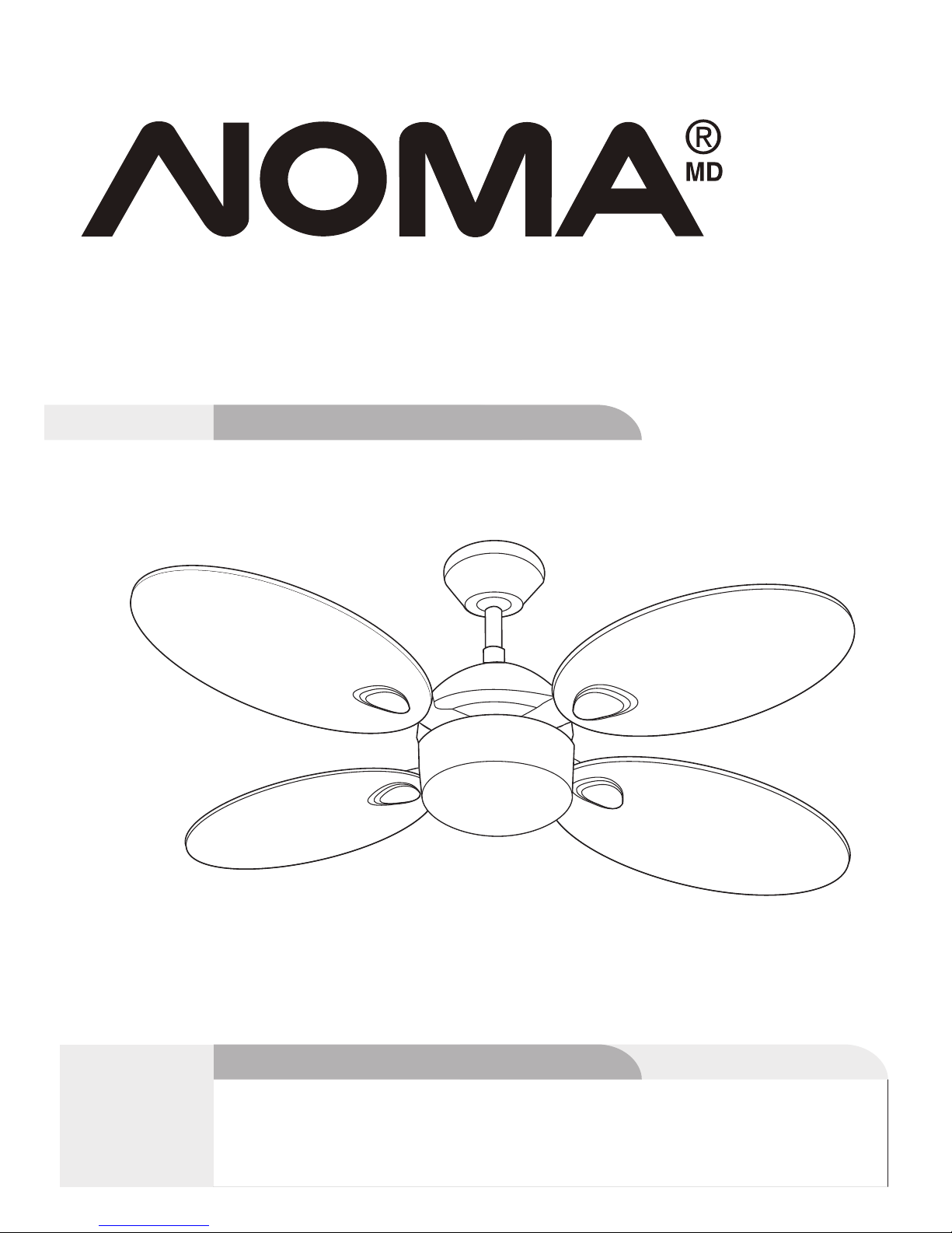
Scandinavian Ceiling Fan
model nos. : 052-4345-2/052-6934-8
Instruction Manual
Toll-free: 1-866-827-4985
IMPORTANT: Please read and understand this manual before any assembly.
Before beginning assembly of product, make sure all parts are present.
Compare parts with exploded view. If any part is missing, or if you have any
questions, contact customer service at 1-866-827-4985 (toll-free).
V5. 2016
Page 2

Table of Contents
Technical Data
Important Safety Instructions
Parts List
Parts Locations
Before Installation
Installation
Operation
Care and Maintenance
Troubleshooting
Warranty
2
2
3
4
5
6
8
14
16
16
18
Technical Data
Table of Contents
Operating voltage: 120 V/60 Hz
Power consumption: Fan only: 45 W (Maximum)
Bulbs: One E12 candelabra-base bulb (60 W maximum)
Page 3
WARNING!
or circuit breaker box before installing, servicing or cleaning.
WARNING!
WARNING!
WARNING!
NOTE:
DO NOT use the ceiling fan if it shows any sign of damage or if it has been dropped.
DO NOT expose the ceiling fan to rain or moisture. Do not operate it outdoors or with wet hands.
DO NOT operate the fan without blades.
DO NOT insert foreign objects between the rotating blades.
Pay special attention to the fan and blades when cleaning, painting or working near the fan.
To prevent injury, make sure the blades are not bent and that there are no objects within the
rotation area.
Do not reverse the rotation until blades have come to a complete stop.
The ceiling fan must be grounded as a precaution against possible electric shock. Electrical
installation should be done or approved by a licensed electrician.
Follow the recommended instructions for the proper method of wiring your ceiling fan. If you do
not know enough about electrical wiring, have the fan installed by a licensed electrician.
The outlet box and joist must be securely mounted and capable of reliably supporting at least
35 lb (15.9 kg).
Use only outlet boxes marked “Acceptable for Fan Support” and use the supplied outlet box
screws. Most outlet boxes commonly used to support light fixtures are not acceptable for fan
support and may need to be replaced. Consult a qualified electrician if in doubt.
The fan must not be installed in a ceiling thermally insulated to a value greater than R40.
To reduce the risk of electric shock, this fan must be installed with a wall-isolating control/switch.
All screws must be checked and re-tightened where necessary.
Only use the parts and accessories supplied with this product, or specifically
designated for use with this product by the manufacturer. Substitution with
parts and accessories not designated by the manufacturer could result in
personal injury or property damage.
This ceiling fan is designed for household use only and not for commercial applications.
No responsibility is accepted for damage resulting from improper use or
non-compliance with the instructions.
The important precautions, safeguards, and instructions appearing in this manual are
not meant to cover all possible situations. It must be understood that common sense
and caution are factors that cannot be built into the product.
Not suitable for use with SOLID-STATE speed controls.
SAVE THESE INSTRUCTIONS
IMPORTANT: RETAIN FOR FUTURE REFERENCE, AND READ CAREFULLY.
Important Safety Instructions
The fan must be mounted with the blades at least 6’ 11” (2.1 m) above the floor to prevent
accidental contact with the blades.
All installation should be conducted in accordance with the national and local wiring codes,
including fire-rated construction. Use the national codes if local codes do not exist.
circuit breaker box before installing, servicing, or cleaning.
Page 4
Toll-free: 1-866-827-4985 · model nos. 052-4345-2/052-6934-8
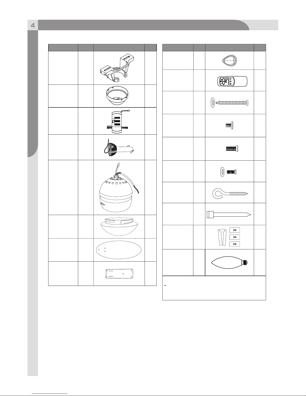
Parts List
Mounting
Bracket
Canopy
A
Receiver
L
Downrod
Assembly
B, C,
D
Motor with
Light Kit
F, G
1
Glass Shade
Blade
Blade Arm
Blade
Decoration
Remote
Control
H
I
J
K
M
4
4
Wood Screw
with Flat
Washer
Blade Screw
Extra Blade
Bracket
Screw
Mouting
Screw with
Split Washer
Balancing Kit
2
13
1
1
2
N
N
Notes:
Parts# N listed in the right column are
packed in hardware bag. (Hardware not
shown to actual size.)
Name No. Illustration Qty. Name No. Illustration Qty.
1
1
1
1
1
4
O
N
N
P
Bulb
(E12 X 60 W)
1
E
1
1
N
N
1
“J” Hook
Zip Tie
Page 5
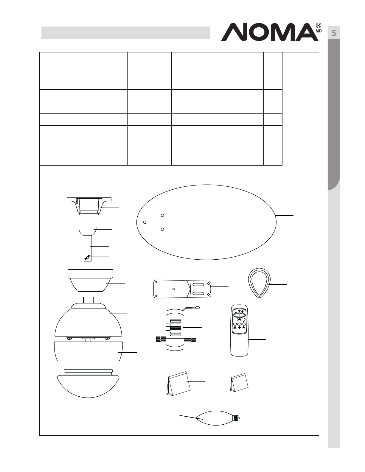
Parts Locations
A
B
C
E
F
G
H
J
K
L
M
N
O
No. Description Qty.
A Mounting Bracket 1
B Nylon Ball 1
C Downrod 1
D Pin 1
E Canopy 1
F Motor Housing 1
G Light Kit 1
H Glass Shade 1
D
No. Description Qty.
I Blade 4
J Blade Arm 4
K Blade Decoration 4
L Receiver 1
M Remote Control 1
N Parts Pack 1
O Balance Pack 1
P Bulb (E12 X 60 W) 1
I
P
Page 6
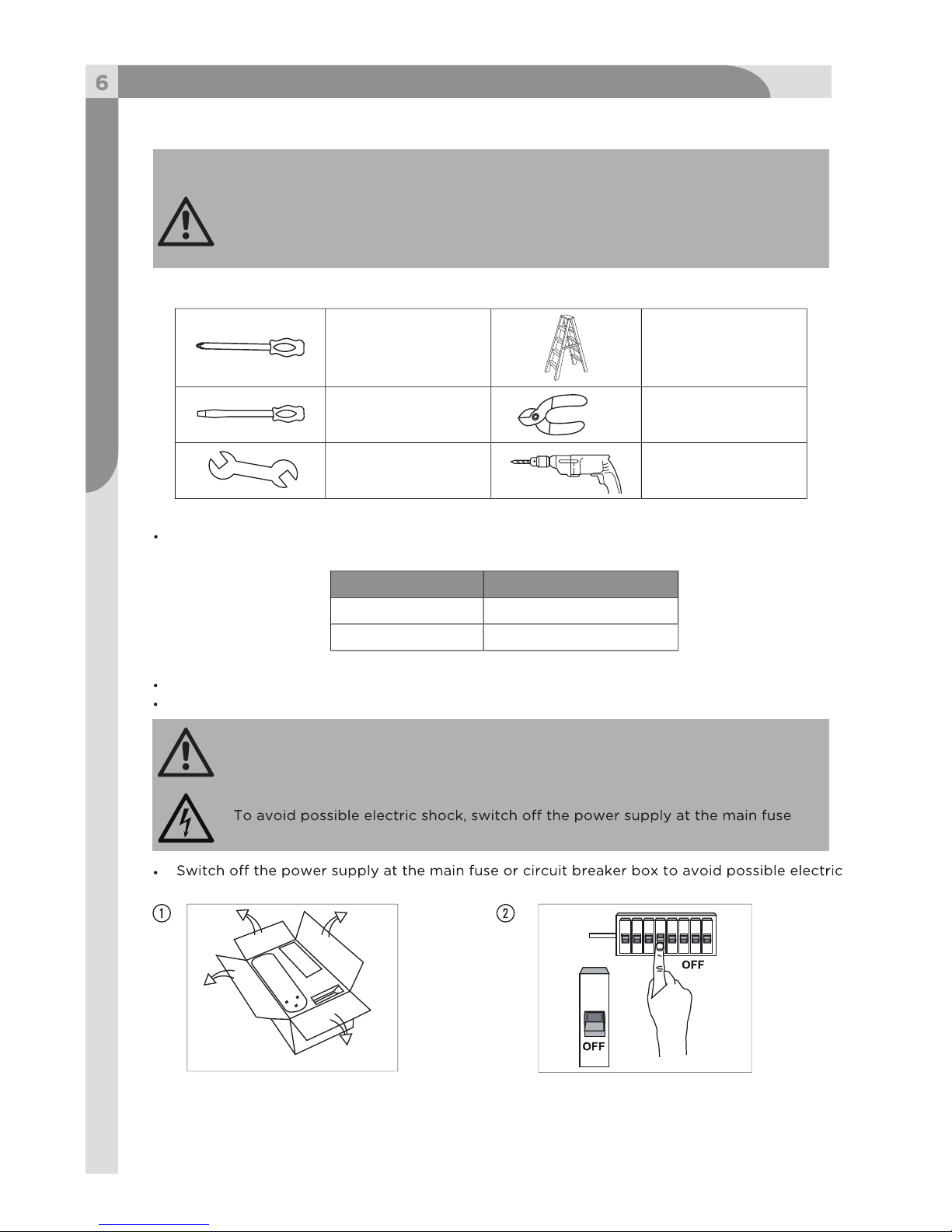
1 x cross-head
screwdriver
1 x wrench
1 x stepladder
1 x wire stripper
/pliers
1 x drill
Up to 50' (15 m) 14
50-100' (15-30 m) 12
Toll-free : 1-866-827-4985 · model nos. 052-4345-2/052-6934-8
WARNING!
WARNING!
Do not install or use the ceiling fan if any part is damaged or missing.
WARNING!
or circuit breaker box before installing, servicing or cleaning.
Tools Needed for Assembly (not supplied):
Materials
Unpacking Instructions
Wire Length Wire Size (A.W.G.)
Read each step carefully before beginning any installation and make sure you
understand each step.
Keep children and pets away during installation.
Keep fingers away from the places where they can be pinched or injured.
Wiring, outlet box and box connectors must be of the type required by the local code.
The minimum wire should be a three-conductor (two-wire with ground) of the following sizes:
Place all parts from the box on a working space in a cleared area.
1 x flat screwdriver
Unpack and inspect carefully to make sure all parts are included and not damaged (fig. 1).
shock (fig. 2).
Before Installation
Page 7
Before Installation
Choosing a Location for the Ceiling Fan
CAUTION! If there is light fixture at your
chosen location, remove the light
fixture first. Before removal, ensure to
fuse or circuit breaker box.
Choosing Mounting Styles
WARNING!
The outlet box and joist must be securely mounted and capable of reliably
supporting at least 35 lb (15.9 kg).
To reduce the risk of electric shock, mount the fan only to an outlet box marked
“Acceptable for Fan Support”, and use the supplied outlet box screws. Most outlet
boxes commonly used to support light fixture are not acceptable for fan support
and may need to be replaced. Consult a qualified electrician if in doubt.
Flush-mount installation (for lower ceilings) Drop-mount installation (for normal ceilings)
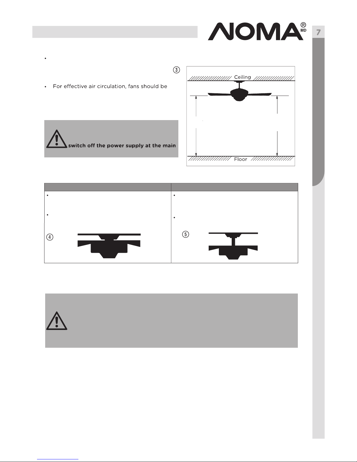
Choose a location where there is a high
enough ceiling clearance, at least 6’ 11”
(2.1 m) between the floor and the blades
(fig. 3).
located in the centre of the room, or a
minimum of 32” (81.3 cm) from adjacent
walls or obstructions.
This method is recommended if maximum
headroom is required. The ceiling must be
completely horizontal and level (fig. 4).
Follow step 1-9, omitting step 3 in the
manual.
This method is recommended if the ceiling
is sloped or vaulted or if the ceiling is
extra high, requiring a downrod (fig. 5).
Follow steps 1-9, omitting step 2 in the
manual.
≥6’ 11”(2.1 m)
Page 8
Installation
Toll-free: 1-866-827-4985 · model nos. 052-4345-2/052-6934-8
1. Installing Mounting Bracket
WARNING! The mounting bracket must sit firmly against the outlet box. If the
outlet box is recessed, remove the wall board until the mounting bracket comes
into contact with the box. If bracket and/or outlet box are not securely attached,
the fan could wobble or fall.
Before drilling, ensure there are no electrical wires or water pipes behind the
drill spots.
While drilling, we recommend wearing protective goggles and hearing
protection.
CAUTION!
Normal masonry ceiling Wooden ceiling
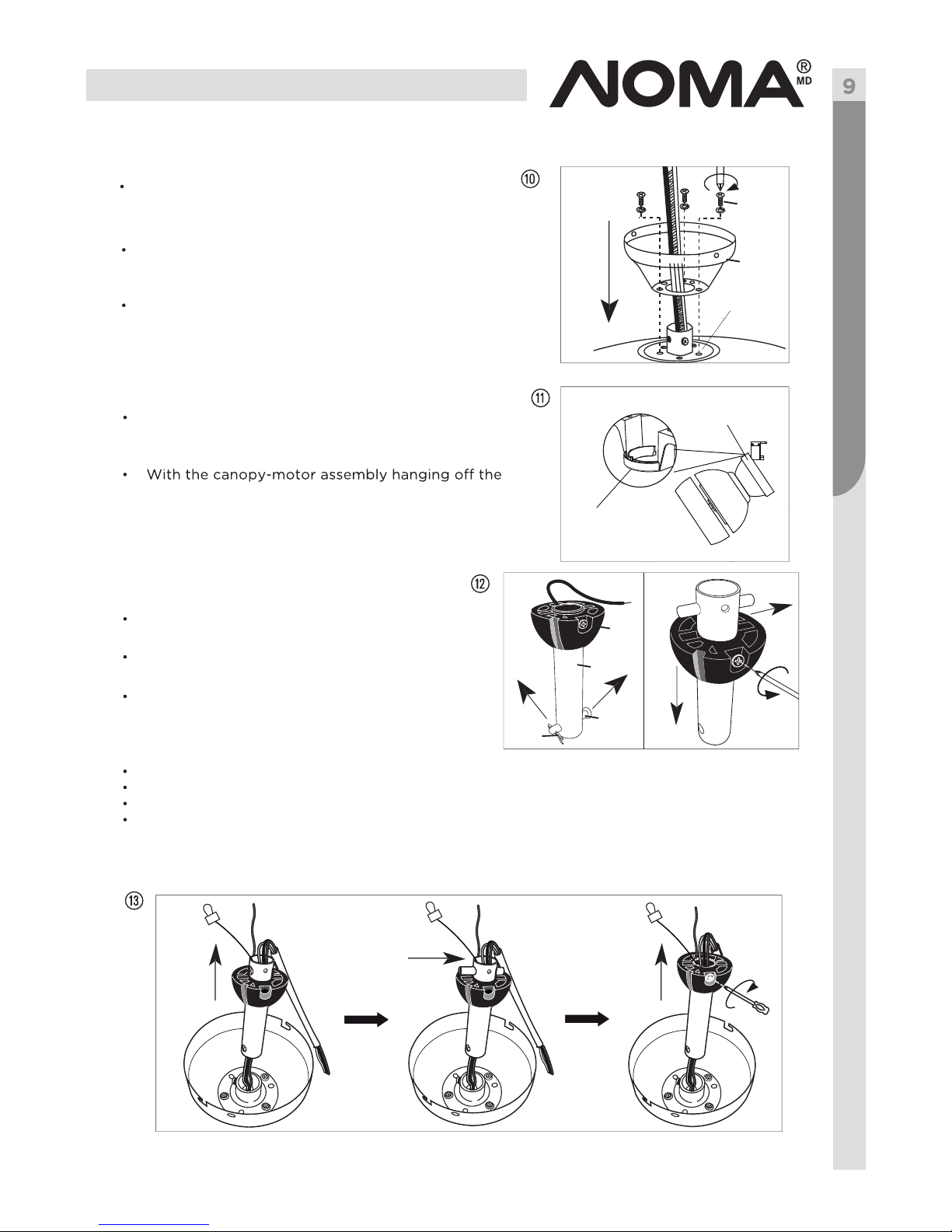
Remove the four sets of side screws from mounting
bracket and save for future use (fig. 6).
Attach the mounting bracket to the normal masonry
ceiling or wooden ceiling as indicated below.
Securely attach the mounting bracket to
an outlet box marked “Acceptable for Fan
Support”, using the supplied outlet box
screws with lock washers (fig. 7).
Drill two mounting holes in the ceiling joist.
Securely attach the mounting bracket to
the ceiling, using the two sets of long
wood screws with flat washers (fig. 8).
Mounting
bracket
Mounting
bracket
Flat washer
Lock washer
Attach the blade decoration and blade
bracket to the blade (fig. 9).
Apply the blade screws and secure properly
(fig. 9).
2.1 Blade Assembly
Note: This fan includes four dual-finished
blades. Depending on personal
preference, choose the side that best
suits the décor or furniture of your
room.
Blade screw
Blade
Blade decorative
Blade arm
2. Flush-mount Installation (skip step 3)
Page 9
Installation
Guide all the wires through the base of the canopy
(fig. 10).
Attach the canopy directly to the motor top and
tighten with the three sets of coupling screws with
split washers (fig. 10).
Raise the canopy-motor assembly to the mounting
bracket’s hook and hang by the hole on the canopy.
This allows for hands-free wiring (fig. 11).
mounting bracket’s hook, follow the wiring instructions
(step 4).
Remove the clip and peaked pin from the
downrod (fig. 12).
Remove the ball screw from the nylon ball
and save for future use (fig. 12).
Slide the ball down, without removing it.
The pin is now exposed. Remove the pin
and save for future use (fig. 12).
Place the canopy on top of the motor housing.
Carefully thread the silver cord and all the wires through the downrod assembly.
Insert the pin into the downrod.
2.2Canopy Assembly
Remove three of the six screws and lock washers
(every other one) securing the motor collar to the
top of the fan motor housing (fig. 10).
2.3 Hanging Fan Assembly to Mounting Bracket
3. Drop-mount Installation
3.2 Securing Nylon Ball
3.1 Dismantling Downrod Assembly
Screw
Canopy
Nylon
ball
Downrod
Peaked
pin
Clip
Slide the ball up until the pin fits firmly into the ball. Insert the ball screw into the
ball and tighten properly (fig. 13).
Canopy
Mounting
bracket
Motor collar
Page 10
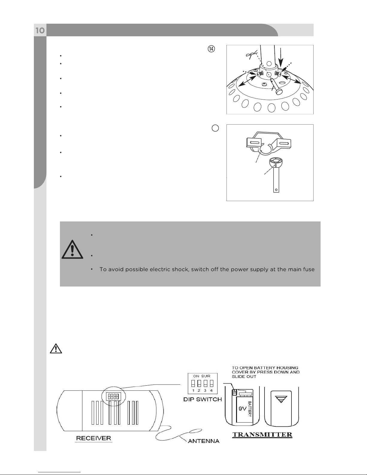
15
Installation
Toll-free: 1-866-827-4985 · model nos. 052-4345-2/052-6934-8
Raise the canopy.
Loosen the two downrod set screws on the
coupling (fig. 14).
Insert the downrod into the coupling. Make sure to
align the holes of these two parts.
Install the peaked pin through the aligned holes and
secure it with the clip.
Tighten the two downrod set screws on the coupling
(fig. 14).
Carefully lift the fan assembly and place it on the
mounting bracket.
Rotate the fan assembly until the notch on the nylon
ball fits against the ridge on the mounting bracket
(fig. 15).
With the mounting bracket holding the fan assembly,
follow the wiring instructions (step 4).
All wiring must be in accordance with national and local electrical codes,
including fire-rated construction. If you are unfamiliar with wiring, consult
a qualified electrician.
If you are not sure whether the electrical outlet box and fan are grounded,
contact a licensed electrician for advice. These parts must be grounded!
or circuit breaker box before installing, servicing or cleaning.
3.3 Securing Downrod Assembly
3.4 Hanging Fan Assembly to Mounting Bracket
4. Wiring Instructions
4.1 Installing Receiver Assembly
WARNING!
ScrewClip
Peaked
pin
Nylon ball
Mounting
bracket
Remote and Receiver Pairing
Codes are set by pushing the location of the dip switches located on the transmitter and
receiver up or down. It is important that the code used for both the remote and receiver
are identical for the two devices to be able to communicate; otherwise the remote will
not be able to control the fan.
If you plan to install more than one fan then each fan will require the remote and receive to
use a unique code, or else one remote will be able to control more than one fan.
Page 11
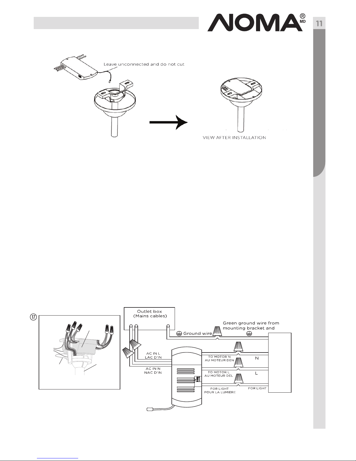
Installing Receiver Assembly
Once the connection has been made, the receiver inserts into the drop rod hanging
bracket. The canopy comes up to cover the receiver and bracket.(fig. 16).
Installation
Between fan and receiver:
· Connect the black wire marked “L” from the fan to the black wire marked “TO MOTOR L”
from the receiver.
· Connect the blue wire marked “FOR LIGHT” from the fan to the blue wire marked “FOR
LIGHT” from the receiver.
· Connect the white wire marked “N” from the fan to the WHITE wire marked “TO MOTOR
N” from the receiver.
Between receiver and mains:
· Connect the black live wire marked “AC IN L” from the receiver to the live wire (typically
black) from the outlet box.
· Connect the white neutral wire marked “AC IN N” from the receiver to the neutral wire
(typically white) from the outlet box.
· Connect the green ground wires from the mounting bracket and nylon ball to the ground
wire (bare or green) from the outlet box.
nylon ball
Downrod
Receiver
Antenna:
DO NOT CUT
OR SPLICE
!
8a
4.2 Making Connections
Page 12

Installation
Toll-free: 1-866-827-4985 · model nos. 052-4345-2/052-6934-8
Hold the bare metal leads together and twist until tight.
After all connections are done, turn the splices upward and push them carefully upward through
the mouting bracket into the outlet box.
Spread the wires apart so that the green and white wires are on one side of the outlet box and the
black and blue wires are on the other side of the outlet box.
Warning!
Be sure no bare wire or wire strands are visible after making connections.
While connecting wires, make sure to:
Note: The silver cord is only a safety cable (fig. 19).
You can wrap it over the mounting bracket and
loop it into the hook on the mounting bracket or
alternatively, secure it to the ceiling, using the
provided short wood screw and lock washer.
Hold the fan assembly by the canopy and
raise it to align the holes in the canopy
with the holes in the mounting bracket.
Diagonally apply two sets of side screws
with lock washers to the mounting brcket.
Do not tighten the side screws at this stage.
Hang the two “L” slots of the canopy on
the mounted side screws (fig. 20).
Diagonally apply another two sets of side
screws with lock washers. Tighten all the
side screws properly.
5. Fan Assembly to Mounting Bracket
Match up the wires first.
Insert the twisted ends into a wire connector and turn the wire connector until tight (fig. 18).
Canopy
Page 13

Installation
Remove all the blade bracket screws with
split washers from the motor bottom, through
the oval slot on the light kit (fig. 21).
Attach one blade assembly to the motor
bottom and secure with the blade bracket
screws and split washers (fig. 22).
Repeat the above procedures for the other
three blade assemblies.
Install one E12 candelabra bulb (60 W
maximum) into the light
socket (fig. 23).
6. Blade Assembly to Motor
7. Installing Bulb
Note: The dimmer function can not be
used if CFL bulb is used. There is
only ON/OFF function.
Light kit
Blade
screw
Caution! Your fan has an energy-saving wattage limiter. If you replace the bulbs
always below 190 W.
bulb wattage is
23
Page 14

Installation
Operation
Toll-free: 1-866-827-4985 · model nos. 052-4345-2/052-6934-8
8. Installing Glass Shade
Attach the glass shade to the light kit and
turn clockwise until tight (fig. 24).
Now your ceiling fan is assembled and ready
for use.
Forward and Reverse Function
Downward air flow Upward air flow
Ceiling fans work best by blowing air
downward (counter-clockwise blade
rotation) in warm weather to cool the
room with a direct breeze (fig. 26).
In winter, having the fan draw air upward
(clockwise blade rotation) will distribute
the warmer air trapped at the ceiling
around the the room without causing
a draft (fig. 27).
· Restore power to ceiling fan and test for proper
operation.
· The fan remote control controls the fan settings:
Note: Do not use the reverse switch when the fan blades are in motion.
HI: Turn on the fan at high speed.
MED: Turn on the fan at medium speed.
LOW: Turn on the fan at low speed.
LIGHT:
ON/OFF: Press and release immediately to turn
DIMMER: Press and hold on to dim or brighten
lights to the desired level and release
(only for the tungsten bulb).
LIGHT
ON/OFF
HI
MED
DIMMER
FAN OFF
LOW
Glass shade
This ceiling fan is equipped with a reverse switch for downward or upward air flow.
9
V
B
a
t
t
e
r
y
Install the 9 V battery (included). To prevent damage to transmitter
remove the battery if not used for long periods .
Page 15

Operation
Changing Airflow Direction
Balancing Kit
Side Description
complete stop.
Slide the reverse switch on the light kit.
Restart the fan.
Left Downward air flow (Forward)
This balancing kit should be used only if there is an unacceptable amount of fan wobble after all
installations are correctly completed (fig. 29).
In case of excessive fan wobble, do as below:
Switch on the fan and choose the fan speed at which the fan wobbles the most.
Switch on the fan to check whether the wobble has increased or decreased. Switch the fan
noting the blade on which the greatest improvement is achieved.
Replace the balancing clip on the blade that shows the greatest improvement. Move the
balancing clip inward and outward, and operate the fan to find the position where the
balancing clip gives the greatest improvement.
Remove the balancing clip and secure the balancing weight (using a provided sticker) on the
top of the blade, along the centre line near the point where the balancing clip was positioned.
If the fan wobble persists, repeat the above procedures and add a second (or more) balancing
weight.
Right Upward air flow (Reverse)
Reverse
switch
balancing clip, halfway between the blade bracket and the blade tip of the trailing edge
(fig. 30).
Blade
Blade
arm
Page 16

Toll-free: 1-866-827-4985 · model nos. 052-4345-2/052-6934-8
Warning!
Cleaning
Problem
Possible reason
Solution
Care and MaintenanceTroubleshooting
or circuit breaker box before installing, servicing or cleaning.
Never clean the fan while in use!
Because of the fan’s natural movement, some connections may become loose. Check the
support connections, brackets and blade attachments regularly. Make sure they are secure.
There is no need to oil your fan. The motor has permanently-lubricated bearings.
If the ceiling fan works abnormally, follow the instructions below or consult a qualified
electrician.
WARNING!
main fuse or circuit breaker box before servicing.
Fan is noisy
during
operation
Blade screws are loose.
The mounting bracket or canopy is
loose.
Screws securing decorative housing
to mounting bracket are loose.
Glass shade is loose.
Screws securing downrod to
mounting bracket are loose.
Wire connectors are vibrating
against the inside of the canopy.
Light kit or light bulb is not firmly
attached.
Canopy is rattling against ceiling.
Motor housing screws are loose.
Tighten the blade screws.
Check and fasten the screws.
Check and fasten the screws.
Tighten by hand, as necessary.
Check and fasten the screws.
Disconnect power at fuse box, loosen
canopy and reposition connectors.
Remove and reattach.
Be sure canopy is not touching ceiling.
Check and fasten the screws.
Check main fuse and branch circuit fuses
or circuit breaker. Repair as necessary.
Check all the wire connections to fan and
housing wiring. Repair as necessary.
Make sure the reverse swith is set to one
side only.
Check and ensure the remote works.
Fuse or circuit breaker is blown.
Loose or incorrect power line,
connections to the fan or switch
wires.
Reverse switch is stuck in the middle.
Remote is not working.
Fan does
not start
When cleaning the fan, use a soft brush or lint-free cloth to prevent scratching. A vacuum
cleaner brush nozzle can remove heavier dust.
Remove surface smudges or accumulated dirt and dust using a mild detergent and a slightly
dampened cloth. Never use abrasive cleaning agents, as they will damage the finish.
Clean wood finish blades with a furniture polishing cloth. Occasionally apply a light coat of
furniture polish for added protection and beauty.
To prevent bending the blades during cleaning, support the blades so that no pressure is
applied to them.
Page 17

Troubleshooting
Problem Possible reason
Solution
Light does
not work
Wires are not properly connected.
Light bulb is faulty.
This fan is equipped with a 190 W
LIMITER that will automatically turn
the light o if the total wattage
exceeds the maximum wattage level.
Remote is not working.
Fan is in reverse mode (blades are
moving in a clockwise direction).
Fan is not properly located.
Screws securing blades to motor are
losse.
Screws securing blade assembly are
loose.
Canopy and mounting bracket are
not tightened securely.
Blades are unbalanced.
Non-match coding between remote and
receiver.
Ensure wire connector in the switch
housing is connected.
Remove light bulb and replace with a
new one of the same type.
with lower wattage bulbs so that the
total wattage will be below 190 W.
Check and ensure the remote works.
Counter-clockwise (forward) direction is
recommended in warm weather. Switch
to stop. Use the eraser end of a pencil to
set the forward/reverse switch to the left
side.
Adjust the fan so that the ends of the
blades have at least 12” (30 cm) clearance
from walls or other obstructions, in the
centre of the room.
Tighten the screws.
Tighten the screws.
Tighten the mounting bracket to the
outlet box.
Check by selecting a point on the ceiling
above the tip of one of the blades.
Measure this distance and ensure all
blades are same (fig. 31). If all blade
levels are not equal, adjust accordingly.
If fan woddle persists, apply the balancing
kit (see page 15).
fuse or circuit breaker box. Wait for at
least 10 seconds and switch on the power
supply again.
Within 30 seconds after power supply is
switched on again, press and hold buttons
1 and 3 simultaneously for five seconds.
The red LED indicator flashers.
Now the remote and receiver are paired.
The fan runs at low speed and with the
Fan does
not seem to
provide the
expected
Fan
wobbles
or shakes
excessively
Remote
does not
work
Used electrical appliances are recyclable and should not be discarded in your regular
domestic waste. Please actively support us in conserving resources and protecting the
environment by returning this appliance to a collection centre (if available).
Battery reclamation (please keep to comply with the local law).
ENVIRONMENTAL PROTECTION
Page 18

Toll-free: 1-866-827-4985 · model nos. 052-4345-2/052-6934-8
Warranty
This Noma product carries a limited ten (10) year warranty against defects in the motor, and a one (1) year
warranty against defects in workmanship and materials. Noma Canada agrees to replace the defective
product free of charge within the stated warranty period, when returned by the original purchaser with proof
of purchase. This product is not guaranteed against wear or breakage due to misuse and/or abuse.
Made in China
Imported by
Noma Canada, Toronto, Canada M4S 2B8
Subject to the conditions and limitations described below, this product, if returned to us with proof of
purchase within the stated warranty period and if covered under this warranty, will be repaired or
replaced (with the same model, or one of equal value or specification), at our option. We will bear the
cost of any repair or replacement and any costs of labor relating thereto.
These warranties are subject to the following conditions and limitations:
a) A bill of sale verifying the purchase and purchase date must be provided;
b) This warranty will not apply to any product or part thereof which is worn or broken or which has
become inoperative due to abuse, misuse, accidental damage, neglect or lack of proper installation,
operation or maintenance (as outlined in the applicable owner’s manual or operating instructions)
or which is being used for industrial, professional, commercial or rental purposes;
c) This warranty will not apply to normal wear and tear or to expendable parts or accessories that
may be supplied with the product that are expected to become inoperative or unusable after a
reasonable period of use;
d) This warranty will not apply to routine maintenance and consumable items such as, but not limited
to, fuel, lubricants, vacuum bags, blades, belts, sandpaper, bits, fluids, tune-ups or adjustments;
e) This warranty will not apply where damage is caused by repairs made or attempted by others
(i.e. persons not authorized by the manufacturer);
f) This warranty will not apply to any product that was sold to the original purchaser as a
reconditioned or refurbished product (unless otherwise specified in writing);
g) This warranty will not apply to any product or part thereof if any part from another manufacturer
is installed therein or any repairs or alterations have been made or attempted by unauthorized
persons;
h) This warranty will not apply to normal deterioration of the exterior finish, such as, but not limited
to, scratches, dents, paint chips, or to any corrosion or discoloring by heat, abrasive and chemical
cleaners; and
i) This warranty will not apply to component parts sold by and identified as the product of another
company, which shall be covered under the product manufacturer’s warranty, if any.
Additional Limitations
This warranty applies only to the original purchaser and may not be transferred. Neither the retailer nor
the manufacturer shall be liable for any other expense, loss or damage, including, without limitation,
any indirect, incidental, consequential or exemplary damages arising in connection with the sale, use or
inability to use this product.
Notice to Consumer
This warranty gives you specific legal rights, and you may have other rights, which may vary from
province to province. The provisions contained in this warranty are not intended to limit, modify, take
away from, disclaim or exclude any statutory warranties set forth in any applicable provincial or
federal legislation
Page 19

Ventilateur de plafond
Scandinavian
Numéro sans frais : 1 866 827-4985
Nos de modèles : 052-4345-2/052-6934-8
Guide d’utilisation
IMPORTANT : Veuillez lire et bien comprendre ce guide avant de procéder à
l’assemblage. Avant de procéder à l’assemblage du produit, assurez-vous
que toutes les pièces sont présentes. Comparez les pièces à la vue éclatée.
S’il manque des pièces, ou si vous avez des questions, communiquez avec le
service à la clientèle en composant le 1 866 827-4985.
V5. 2016
Page 20

Table des matières
Données techniques
Consignes de sécurité importantes
Liste des pièces
Emplacements des pièces
Avant l’installation
Installation
Fonctionnement
Entretien
Dépannage
Garantie
2
2
3
4
5
6
8
14
16
16
18
Données techniques
Table des matières
Tension de fonctionnement : 120 V/60 Hz
Consommation électrique : 45 W (max.) pour le ventilateur seulement
Ampoules : une ampoule E12 à petit culot (60 W max.)
Page 21

AVERTISSEMENT! Pour éviter tout risque de choc électrique, coupez l’alimentation au
tableau de distribution ou au boîtier de disjoncteurs avant d’installer, de réparer ou de
nettoyer le produit.
AVERTISSEMENT!
AVERTISSEMENT!
AVERTISSEMENT!
REMARQUE :
• Ne faites PAS fonctionner le ventilateur de plafond s’il montre des signes d’endommagement ou s’il est tombé.
• N’exposez PAS le ventilateur de plafond à la pluie ni à l’humidité. Ne faites PAS fonctionner le ventilateur à
l’extérieur ou avec les mains mouillées.
• Ne faites PAS fonctionner le ventilateur sans pales.
• N’introduisez JAMAIS de corps étrangers entre les pales en rotation.
• Faites particulièrement attention au ventilateur et aux pales lorsque vous nettoyez, peignez ou travaillez près
du ventilateur.
• Le ventilateur doit être installé avec les pales à au moins 6 pi 11 po (2,1 m) au-dessus du sol pour éviter un
contact accidentel avec les pales.
• Pour éviter les blessures, assurez-vous que les pales ne sont pas pliées et qu’il n’y a pas d’objets dans la zone
de rotation.
• N’inversez pas la rotation des pales avant qu’elles se soient arrêtées de tourner.
• L’installation au complet doit être eectuée conformément aux codes de câblage nationaux et locaux, incluant
ceux concernant le feu. S’il n’existe pas de codes locaux, appliquez les codes nationaux.
• Le ventilateur de plafond doit être relié à la terre par mesure de précaution contre les risques de choc
électrique. L’installation électrique doit être eectuée ou approuvée par un électricien qualifié.
• Suivez les recommandations fournies pour câbler correctement votre ventilateur de plafond. Si vous ne
possédez pas de connaissances susantes en matière de câbla ge électrique, confiez l’installation du ventilateur
à un électricien qualifié.
• La boîte de sortie électrique et la solive de plafond doivent être solidement fixées et capables de supporter de
manière fiable au moins 35 lb (15,9 kg).
• Utilisez seulement des boîtes de sortie électrique portant la mention « Acceptable for Fan Support » (peut
supporter un ventilateur) et utilisez les vis fournies avec la boîte de sortie électrique. La plupart des boîtes de
sortie électrique couramment utilisées pour les luminaires ne sont pas adaptées aux ventilateurs et doivent être
remplacées. En cas de doute, consultez un électricien qualifié.
• Le ventilateur ne doit pas être monté sur un plafond thermiquement isolé à une valeur supérieure à R40.
• Pour réduire le risque de choc électrique, ce ventilateur doit être installé avec un commutateur/interrupteur
mural.
• Toutes les vis doivent être vérifiées et resserrées si nécessaire.
Utilisez uniquement les pièces et accessoires fournis avec ce produit, ou expressément
conçus par le fabricant pour être utilisés avec ce produit. L’utilisation de pièces et
accessoires autres que ceux conçus par le fabricant pourrait entraîner des blessures ou
des dommages matériels.
• Ce ventilateur de plafond est conçu pour une utilisation domestique seulement et non
pas pour des applications commerciales. Nous ne saurions être tenus responsables des
dommages résultant d’une utilisation non conforme aux instructions ou du non-respect
des instructions.
• Les importantes mises en garde et directives contenues dans ce guide ne couvrent pas
de façon exhaustive toutes les situations possibles. L’utilisateur doit comprendre que le
bon sens et la prudence sont des facteurs qui ne peuvent pas être intégrés à ce produit.
Ne doit pas être utilisé avec une commande de vitesse à semi-conducteurs.
CONSERVEZ CES CONSIGNES.
IMPORTANT : CONSERVEZ CE GUIDE AUX FINS DE CONSULTATION ULTÉRIEURE, ET
LISEZ-LE ATTENTIVEMENT.
Consignes de sécurité importantes
Pour éviter tout risque de choc électrique, coupez l’alimentation sur le panneau
électrique ou dans la boîte de fusibles avant d’installer, de réparer ou de nettoyer
ce produit.
Page 22

Numéro sans frais: 1 866 827-4985 · Nos de modèles : 052-4345-2/052-6934-8
A
Récepteur L
Assemblage
du tube
B, C,
D
Moteur et
ensemble
d’éclairage
F, G
1
Abat-jour en
verre
Pale
Support de
pale
Pièce
décorative
de pale
Télécommande
H
I
J
K
M
4
4
Vis à bois
avec rondelle
plate
Vis de pale
Vis
supplémentaire
pour support
de pale
Vis de
montage avec
rondelle
élastique
Trousse
d’équilibrage
2
13
1
1
2
N
N
Remarques :
Les pièces# N ci-dessus dans la colonne
droite sont emballées dans le sac de
quincaillerie. (La quincaillerie n’est pas illustrée
à taille réelle.)
Liste des pièces
Nom N° Illustration Qté
1
1
1
1
1
4
O
N
N
Nom N° Illustration Qté
1
Ampoule
(E12 X 60 W)
1
E
1
P
N
N
1
Support
de
montage
Couvercle
Page 23

Emplacements des pièces
A
B
C
E
F
G
H
I
J
K
L
M
N
O
N° Description Qté
A Support de montage 1
B Boule en nylon
C Tube
D Goupille
E Socle
F Boîtier du moteur
G Ensemble d’éclairage
H Abat-jour en verre
D
N° Description Qté
I Pale
J Support de pale
K Pièce décorative de pale
L Récepteur
M Télécommande
N
Sac de pièces
O Trousse d’équilibrage
1
1
1
1
1
1
1
4
4
4
1
1
1
1
P Ampoule (E12 X 60 W) 1
P
Page 24

Avant l’installation
1 x tournevis à tête
cruciforme
1 x clé
1 x escabeau
1 x pince à dénuder
1 x perceuse
Jusqu’à 50 pi (15 m) 14
50 à 100 pi (15 à 30 m) 12
Numéro sans frais : 1 866 827-4985 · Nos de modèles : 052-4345-2/052-6934-8
AVERTISSEMENT!
AVERTISSEMENT!
N’installez ou n’utilisez pas le ventilateur de plafond si une pièce est endommagée ou
manquante.
AVERTISSEMENT!
Pour éviter tout risque de choc électrique, coupez l’alimentation sur le panneau
électrique ou dans la boîte de fusibles avant d’installer, de réparer ou de nettoyer
ce produit.
Outils requis pour l’assemblage (non fournis) :
Matériaux
Consignes de déballage
Longueur du fil Calibre de fil (AWG)
Veuillez lire attentivement chaque étape avant de procéder à l’installation et
assurez-vous de comprendre toutes les étapes.
Tenez les enfants et les animaux à l’écart lors de l’installation.
Tenez vos doigts éloignés des endroits où ils risquent d’être pincés ou blessés.
• Les fils de câblage, la boîte de sortie électrique et les capuchons de connexion doivent être
du type requis par les règlements locaux. Le fil doit au minimum comporter trois conducteurs
(deux fils avec fil de terre) aux dimensions suivantes :
1 x tournevis à tête
plate
• Déballez et inspectez soigneusement toutes les pièces pour vous assurer qu’elles sont toutes
incluses et non endommagées (voir figure 1).
• Placez toutes les pièces de la boîte sur une surface de travail dégagée.
• Coupez l’alimentation sur le panneau électrique ou dans la boîte de fusibles pour éviter tout choc
électrique (figure 2).
ARRÊT
ARRÊT
Page 25

Avant l’installation
Choisir un emplacement pour le ventilateur de plafond
ATTENTION! S’il existe déjà un appareil
d’éclairage à l’emplacement choisi,
démontez-le d’abord. Avant de le
démonter, veillez à couper l’alimentation
sur le panneau électrique ou dans la boîte
de fusibles.
Choisir le style de montage
AVERTISSEMENT!
La boîte de sortie électrique et la solive de plafond doivent être solidement fixées et
capables de supporter de manière fiable au moins 35 lb (15,9 kg).
Pour réduire le risque de choc électrique, installez le ventilateur sur une boîte de
sortie électrique portant la mention « Acceptable for Fan Support » (peut supporter
un ventilateur) et utilisez les vis fournies avec la boîte de sortie électrique. La plupart
des boîtes de sortie électrique couramment utilisées pour les luminaires ne sont pas
adaptées aux ventilateurs et doivent être remplacées. En cas de doute, consultez un
électricien qualifié.
(pour les plafonds bas)
Montage surbaissé
(hauteur normale sous le plafond)
• Choisissez un emplacement où la surface de
dégagement du plafond entre le sol et les
pales est d’au moins 6 pi 11 po (2,1 m)
(figure 3).
• Pour ventiler ecacement, le ventilateur doit
être situé au centre de la pièce ou à une distance
d’au moins 32 po (81,3 cm) des murs adjacents ou
des obstacles.
• Cette méthode est recommandée si une
plus grande hauteur sous plafond est
requise. Le plafond doit être entièrement
horizontal et de niveau (figure 4).
• Suivez les étapes de 1 à 9, sans eectuer
l’étape 3 dans ce guide.
• Cette méthode est recommandée si le
plafond est incliné ou en voûte ou si la
hauteur sous plafond est très grande, ce qui
exige un tube (figure 5).
• Suivez les étapes de 1 à 9, sans eectuer
l’étape 2 dans ce guide.
≥6 pi 11 po (2,1 m)
Plafond
Plancher
Page 26

Installation
Numéro sans frais : 1 866 827-4985 · Nos de modèles : 052-4345-2/052-6934-8
1. Installation du support de montage
AVERTISSEMENT! Le support de montage doit être fixé solidement contre la boîte de
sortie électrique. Si la boîte de sortie électrique est encastrée, retirez la plaque murale
jusqu’à ce que le support de montage entre en contact avec la boîte de sortie électrique.
Si le support et/ou la boîte de sortie électrique ne sont pas solidement fixés, le
ventilateur peut devenir branlant ou peut tomber.
• Avant de percer un trou, assurez-vous qu’il n’y a aucun fil électrique ou tuyau d’eau
derrière l’endroit de perçage.
• Nous vous recommandons de porter des lunettes de sécurité et un dispositif de
protection auditive lors du perçage.
ATTENTION!
• Retirez les quatre ensembles de vis latérales avec les
du socle et conservez-les pour une utilisation ultérieure
(figure 6).
• Fixez le support de montage au plafond en plâtre ordinaire ou
au plafond en bois comme illustré ci-dessous.
• Fixez solidement le support de montage à
une boîte de sortie électrique portant la
mention « Acceptable for Fan Support »
(peut supporter un ventilateur), au moyen
des vis et rondelles de blocage fournies
avec la boîte de sortie électrique
(figure 7).
• Percez deux trous de montage dans la solive
du plafond.
• Fixez solidement le support de montage au
plafond, au moyen de deux longues vis à bois
avec des rondelles plates (figure 8).
Plafond en plâtre ordinaire Plafond en bois
Support de
montage
Boîte de sortie
électrique
Vis de boîte de
sortie électrique
Support de
montage
Rondelle plate
Vis à bois
Rondelles de blocage
2.1 Assemblage des pales
• Fixez la pièce décorative de pale et le support de
pale à la pale (figure 9).
• Posez les vis de pales et serrez-les fermement
(figure 9).
Remarque : Ce ventilateur comprend quatre
pales à double revêtement. Selon vos
préférences personnelles, choisissez le côté
qui convient mieux à votre décor ou aux
meubles de la pièce.
Vis de pale
Pale
Pièce décorative de pale
Support de pale
Page 27

Installation
• Acheminez tous les fils à travers la base du socle
(figure 10).
• Fixez le socle directement sur le sommet du moteur et
serrez au moyen des trois vis d’accouplement avec
rondelles-frein en étoile (figure 10).
• Levez l’ensemble socle-moteur vers le crochet du support
de montage et suspendez par le trou dans le socle. Ceci
permet de réaliser le câblage à mains libres (figure 11).
• Avec l’ensemble socle-moteur suspendu du crochet au
support de montage, suivez les instructions de câblage
(étape 4).
• Retirez la goupille bêta et le boulon pointu du
tube (figure 12).
• Retirez la vis de la boule en nylon et conservez-la
pour une utilisation ultérieure (figure 12).
• Faites glisser la boule vers le bas, sans la retirer.
La tige est maintenant exposée. Retirez la tige et
conservez-la pour une utilisation ultérieure (figure 12).
• Placez le socle sur le dessus du boîtier de moteur.
• Acheminez soigneusement le cordon argenté et tous
les fils à travers le tube.
• Insérez la tige dans le tube.
• Faites glisser la boule vers le haut jusqu’à ce que la
tige soit fermement logée dans la boule. Insérez la vis
pour boule dans la boule et serrez-la solidement (figure 13).
2.2 Assemblage du socle
• Retirez trois des six vis avec rondelles-frein (toutes
les deux vis; une vis sur deux) fixant la bague du
moteur sur le dessus du bloc-moteur du ventilateur
(fig. 10).
2.3 Suspension du corps du ventilateur au support de montage
3. Montage surbaissé
3.2 Fixation de la boule en nylon
3.1 Désassemblage de l’assemblage de tubes
Vis
Socle
Boule
en nylon
Tube
Boulon
pointu
Goupille
bêta
Support de
montage
Socle
Bague du
moteur
Page 28

Installation
Numéro sans frais : 1 866 827-4985 · Nos de modèles : 052-4345-2/052-6934-8
• Levez le socle.
• Desserrez les deux vis de tube du manchon (figure 14).
• Insérez le tube dans le manchon. Assurez-vous d’aligner les
trous de ces deux pièces.
• Installez le boulon pointu dans les trous alignés et fixez-le au
moyen de la goupille bêta.
• Serrez les deux vis de tube du manchon (figure 14).
• Levez soigneusement le corps du ventilateur et placez-le
sur le support de montage.
• Tournez le corps du ventilateur jusqu’à ce que l’encoche
sur la boule en nylon s’adapte à la saillie sur le support de
montage (figure 15).
• Tandis que le support de montage tient le corps du ventilate ur,
suivez les consignes de câblage (étape 4).
• Le câblage doit être eectué conformément aux codes de l’électricité nationaux et
locaux, incluant ceux concernant les incendies. N’essayez pas d’in staller le
ventilateur sans l’aide d’un électricien qualifié si vous ne maîtrisez pas parfaitement
l’installation des composants électriques.
• Si vous ne savez pas si la boîte de sortie électrique et le ventilateur sont reliés à la
terre, consultez un électricien qualifié. Ces pièces doivent être reliées à la terre.
• Pour éviter tout risque de choc électrique, coupez l’alimentation au tableau de
distribution ou au boîtier de disjoncteurs avant d’installer, de réparer ou de nettoyer
le produit.
3.3 Fixation de l’assemblage de tubes
3.4 Suspension du corps du ventilateur au support de
montage
4. Instructions de câblage
4.1 Mise en place du récepteur
AVERTISSEMENT!
VisGoupille
bêta
Boulon
pointu
Support de
montage
Boule en nylon
Coupler la télécommande au récepteur
• Les codes sont établis en poussant vers le haut ou vers e bas les commutateurs DIP situés sur
le transmetteur et le récepteur. Il est important d'utiliser le même code pour la télécommande
et le récepteur afin que ces deux appareils puissent communiquer; sinon, la télécommande ne
pourra pas commander le ventilateur.
15
Si vous songez à installer plus d'un ventilateur, chaque ventilateur doit utiliser un code unique
pour la télécommande et le récepteur; autrement, une seule télécommande contrôlera tous
les ventilateurs.
Page 29

Installation
4.2 Raccordements
Entre le ventilateur et le récepteur :
• Raccordez le fil noir marqué « L » (sous tension) du ventilateur au fil noir marqué « TO MOTOR
L » (conducteur de phase pour moteur) du récepteur.
• Raccordez le fil bleu marqué « FOR LIGHT » (pour lumière) du ventilateur au fil bleu marqué
« FOR LIGHT » (pour lumière) du récepteur.
• Raccordez le fil blanc marqué « N » (neutre) du ventilateur au fil BLANC marqué « TO MOTOR
N » (conducteur neutre pour moteur) du récepteur.
Entre le récepteur et la boîte de sortie électrique :
• Raccordez le fil sous tension noir marqué « AC IN L » (conducteur de phase) du récepteur au fil
sous tension (normalement noir) de la boîte de sortie électrique.
• Raccordez le fil neutre blanc marqué « AC IN N » (conducteurneutre) du récepteur au fil neutre
(normalement blanc) de la boîte de sortie électrique.
• Raccordez les fils de terre verts du support de montage et de la boule en nylon au fil de terre
(nu ou vert) de la boîte de sortie électrique.
• Insérez le récepteur dans le support de montage du tube. Levez le socle pour couvrir le
récepteur et le support (fig. 16).
Laissez le fil déconnecté et ne le coupez pas
Vue aprés l’installation
Mise en place du récepteur
Tige de
suspension
Récepteur
Antenna:
DO NOT CUT
OR SPLICE
Fil de mise à
la terre
Fil de mise à la terre vert du support
de rotale en nylon’boule
Boîte de jonction
(câbles de secteur)
Page 30

Installation
Numéro sans frais : 1 866 827-4985 · Nos de modèles : 052-4345-2/052-6934-8
• Après avoir eectué tous les raccordements, orientez les jonctions de fils vers le haut et poussez-les
soigneusement vers le haut à travers le support de montage jusqu’à la boîte de sortie électrique.
• Placez les fils vert et blanc d’un côté de la boîte de sortie électrique et les fils noir et bleu de l’autre
côté de la boîte de sortie électrique.
Avertissement!
Assurez-vous qu’aucun fil nu ni brin de fil n’est visible après avoir eectué tous les
raccordements.
Pour le raccordement des fils, assurez-vous de :
• D'apparier les fils en premier lieu.
• De tenir les fils conducteurs nus ensemble pour les entrelacer jusqu’à ce qu’ils soient serrés.
• D'insérer les bouts entrelacés dans un capuchon de connexion et de tourner le capuchon de
connexion jusqu’à ce qu’il soit bien fixé (figure 18).
Remarque : Le cordon argenté n’est qu’un câble de
sécurité (figure 19). Vous pouvez soit l’enrouler autour
du support de montage et le boucler dans le crochet
sur le support de montage, soit le fixer au plafond au
moyen de la vis à bois courte et de la rondelle de
blocage fournies.
5. Fixation du corps du ventilateur au support de
montage
• Tenez le corps du ventilateur par le socle et levez-le
pour aligner les trous du socle sur ceux du support
de montage.
• Posez diagonalement deux vis latérales avec des
rondelles éventail sur le support de montage. Ne
serrez pas les vis latérales à ce stade.
• Accrochez les deux encoches en « L » du socle aux
vis latérales posées (figure 20).
• Posez les deux autres vis latérales avec les
rondelles éventail. Serrez toutes les vis latérales
correctement.
Cordon argenté
Encoche en « L »
Socle
Page 31

Installation
6. Fixation des pales au moteur
• Retirez toutes les vis des supports de pale avec
les rondelles élastiques au bas du moteur dans
l’encoche ovale de l’ensemble d’éclairage (figure 21).
• Fixez un assemblage de pale au bas du moteur au
moyen des vis de support pour pales et des
rondelles élastiques (figure 22).
• Répétez les procédures ci-dessous pour les trois
autres assemblages de pales.
7. Installation de l’ampoule
Installez une ampoule E12 à petit culot (60 W
max.) dans la douille (figure 23).
Remarque : Si une ampoule fluocompacte
est utilisée, le gradateur ne fonctionne pas.
Seul l’interrupteur marche/arrêt fonctionne.
Ensemble d’éclairage
Vis de pale
Attention! Votre ventilateur comporte un limiteur de puissance pour économies
d’énergie. Si vous remplacez les ampoules avec des ampoules dont la puissance
totale dépasse la limite de 190 W, la lumière s’éteint automatiquement. Assurez
-vous que la puissance totale des ampoules est toujours inférieure à 190 W.
Encoche
ovale
Page 32

Installation
Fonctionnement
Numéro sans frais : 1 866 827-4985 · Nos de modèles : 052-4345-2/052-6934-8
8. Installation de l’abat-jour en verre
• Fixez l’abat-jour en verre à l’ensemble d’éclairage
en le tournant en sens horaire jusqu’à ce qu’il soit
fermement attaché (figure 24).
• Maintenant, votre ventilateur de plafond est assemblé
et prêt à l’emploi.
Fonction de marche avant ou arrière
Circulation d’air vers le bas Circulation d’air vers le haut
• En été, les ventilateurs de plafond
fonctionnent mieux lorsqu’ils sou
ent l’air
vers le bas (rotation en sens antihoraire
des pales) pour refroidir la pièce avec une
brise directe (figure 26).
• En hiver, les ventilateurs fonctionnent
mieux lorsqu’ils sou
ent l’air vers le haut
(rotation en sens horaire des pales), ce qui
permet de distribuer l’air chaud retenu au
plafond partout dans la pièce sans
provoquer de courant d’air (figure 27).
MARCHE/ARRÊT
DE LA LUMIÈRE
ÉLEVÉE
MOY
GRADATEUR
ARRÊT DU
VENTILATEUR
BASSE
Abat-jour
en verre
• Ce ventilateur de plafond est doté d’un interrupteur de marche avant/arrière pour faire circuler l’air
vers le haut ou vers le bas.
Marche/arrêt et sélection de vitesse du ventilateur
• Rétablissez l’alimentation du ventilateur de plafond
et testez son fonctionnement.
• La télécommande du ventilateur permet d’activer les
réglages du ventilateur :
ARRÊT : appuyez sur ce bouton pour arrêter le ventilateur.
ÉLEVÉE : appuyez sur ce bouton pour mettre le ventilateur
en marche à vitesse élevée.
MOY. : appuyez sur ce bouton pour mettre le ventilateur en
marche à vitesse moyenne.
BASSE : appuyez sur ce bouton pour mettre le ventilateur
en marche à vitesse basse.
ÉCLAIRAGE :
MARCHE/ARRÊT : appuyez sur ce bouton et relâchez-le
immédiatement pour allumer ou éteindre la lumière.
GRADATEUR : appuyez sur ce bouton et maintenez-le
enfoncé pour réduire ou augmenter l’intensité d’éclairage
au niveau désiré, puis relâchez-le (fonctionne seulement
pour les ampoules à filament de tungstène).
Remarque : N’utilisez pas l’interrupteur marche avant/arrière lorsque les pales du ventilateur sont en
mouvement.
Rétablissez l’alimentation du ventilateur de plafond et testez son
fonctionnement.
Installez la pile de 9 V (incluse). Pour éviter d'endommager l'émetteur,
retirez la pile s'il n'est pas utilisé pendant de longues périodes.
9
V
B
a
t
t
e
r
y
Page 33

Fonctionnement
Changer la direction de la circulation d’air
• Éteignez le ventilateur et attendez son arrêt
complet.
• Faites coulisser l’interrupteur de marche
avant/arrière sur l’ensemble d’éclairage.
• Redémarrez le ventilateur.
Trousse d’équilibrage
Cette trousse d’équilibrage ne doit être utilisée qu’en cas d’oscillation excessive du ventilateur, une
fois toutes les installations eectuées correctement (figure 29).
En cas d’oscillation excessive du ventilateur, procédez comme suit :
• Allumez le ventilateur et choisissez la vitesse à laquelle le ventilateur oscille le plus.
• Éteignez le ventilateur et attendez son arrêt complet. Choisissez une pale et accrochez-y la pince
d’équilibrage, à mi-chemin entre le support de pale et l’extrémité de la pale (figure 30).
Interrupteur
de marche
avant/arrière
Pale
Support
de pale
Côté Description
Gauche Circulation d’air vers le bas (vers l’avant)
Droit Circulation d’air vers le haut (vers l’arrière)
Pince
d’équilibrage
Poids
d’équilibrage
Pince d’équilibrage
• Allumez le ventilateur pour vérifier si l’oscillation a augmenté ou diminué. Éteignez le ventilateur,
fixez la pince d’équilibrage sur une autre pale et testez à nouveau. Répétez cette procédure sur
toutes les pales et notez la pale sur laquelle l’amélioration est la plus marquée.
• Replacez la pince d’équilibrage sur la pale où l’amélioration est la plus marquée. Déplacez la pince
d’équilibrage vers l’intérieur et l’extérieur, et faites fonctionner le ventilateur pour trouver la position
où la pince équilibre au mieux.
• Retirez la pince d’équilibrage et fixez le poids d’équilibrage (au moyen d’un autocollant fourni) sur le
dessus de la pale, le long de la ligne du centre près du point où la pince d’équilibrage était
positionnée.
• Si l’oscillation du ventilateur persiste, répétez les procédures ci-dessus et ajoutez un deuxième (ou
plus) de poids d’équilibrage.
Page 34

Numéro sans frais : 1 866 827-4985 · Nos de modèles : 052-4345-2/052-6934-8
Avertissement!
• Pour éviter tout risque de choc électrique, coupez l’alimentation dans le panneau
électrique ou dans la boîte de fusibles avant d’installer, de réparer ou de nettoyer ce
produit.
• Ne nettoyez jamais le ventilateur en cours de fonctionnement!
Nettoyage
• Utilisez une brosse douce ou un chion non pelucheux pour nettoyer le ventilateur afin de ne pas
le rayer. Une brosse d’aspirateur peut éliminer les grosses particules de poussière.
• Nettoyez les taches de surface ou la saleté et la poussière accumulées en utilisant un détergent
doux et un chion légèrement humide. N’utilisez jamais de nettoyants abrasifs, car ils peuvent
endommager le fini.
• Nettoyez les pales au fini bois à l’aide d’un chion pour polissage des meubles. Appliquez
occasionnellement une légère couche de cire pour meubles pour rehausser la beauté des pales et
pour les protéger.
• Pour éviter de cintrer les pales lors du nettoyage, soutenez-les de façon à n’exercer aucune pression.
EntretienDépannage
Si le ventilateur de plafond fonctionne anormalement, suivez les instructions ci-dessous ou
consultez un électricien qualifié.
Avertissement! Pour éviter tout risque de choc électrique, coupez l'alimentation dans
d’entretien.
• En raison du mouvement naturel du ventilateur, des connexions peuvent se desserrer. Vérifiez les
connexions, les supports et les raccordements des pales régulièrement. Assurez-vous qu’ils sont
bien serrés.
• Il n’est pas nécessaire de lubrifier votre ventilateur. Les roulements du moteur sont lubrifiés en
permanence.
Problème Cause possible Solution
Le ventilateur
fait du bruit
lorsqu’il tourne.
• Les vis du ventilateur sont desserrées.
• Le support de montage ou le socle est
desserré.
• Les vis fixant le boîtier décoratif au support
de montage sont desserrées.
• L’abat-jour en verre est desserré.
• Les vis fixant le tube au support de montage
sont desserrées.
• Les capuchons de connexion vibrent contre
l’intérieur du socle.
• L’ensemble d’éclairage ou les ampoules ne
sont pas solidement fixés.
• Le socle fait un bruit de cliquetis contre le
plafond.
• Les vis du boîtier du moteur sont desserrées.
• Serrez les vis des pales.
• Vérifiez et serrez les vis.
• Vérifiez et serrez les vis.
• Serrez à la main, au besoin.
• Vérifiez et serrez les vis.
• Coupez l’alimentation au tableau de
distribution, desserrez le socle et
repositionnez les capuchons de
connexion.
• Retirez et fixez-les à nouveau.
• Assurez-vous que le socle ne touche
pas le plafond.
• Vérifiez et serrez les vis.
Le ventilateur ne
démarre pas.
• Le fusible est grillé ou le disjoncteur est
déclenché.
• Les raccordements des fils d’alimentation au
ventilateur ou au commutateur sont
desserrés ou incorrects.
• L’interrupteur de marche avant/arrière est
coincé au milieu.
• La télécommande ne fonctionne pas.
• Vérifiez le fusible ou le disjoncteur du
circuit au tableau de distribution
principal ou au boîtier de disjoncteurs.
Réparez au besoin.
• Vérifiez toutes les connexions au
ventilateur et le câblage du boîtier.
Réparez au besoin.
• Assurez-vous que le bouton de marche
avant/arrière est réglé sur un seul côté.
• Vérifiez et assurez-vous que la
télécommande fonctionne.
le panneau électrique ou dans la boîte de fusibles avant d'eectuer des travaux
Page 35

Dépannage
PROTECTION DE L’ENVIRONNEMENT
Problème Cause possible Solution
Le luminaire ne
s’allume pas.
• Les fils ne sont pas bien connectés.
• L’ampoule est défectueuse.
• Ce ventilateur est doté d’un LIMITEUR DE
PUISSANCE de 190 W qui éteint le
luminaire si la puissance totale dépasse le
niveau de puissance maximum.
• La télécommande ne fonctionne pas.
• Assurez-vous que le capuchon de
est bien fixé.
• Retirez l’ampoule et remplacez-la par
une ampoule neuve du même type.
• Éteignez l’appareil et remplacez les
ampoules par des ampoules de
puissance inférieure de sorte que la
puissance totale des ampoules est
inférieure à 190 W.
• Vérifiez et assurez-vous que la
télécommande fonctionne.
Le ventilateur ne
semble pas
fournir les eets
attendus.
• Le ventilateur est en marche inversée (les
pales tournent en sens horaire).
• Le ventilateur n’est pas convenablement
placé.
• La rotation en sens antihoraire (marche
avant) est recommandée en été.
Éteignez le ventilateur et coupez
l’alimentation, puis attendez que les
pales arrêtent de tourner. Utilisez le bout
régler l’interrupteur de marche avant/
arrière sur le côté gauche.
• Réinstallez le ventilateur au centre de la
pièce et assurez-vous que les extrémités
des pales se trouvent à une distance d’au
moins 12 po (30 cm) des murs ou
d'autres obstacles.
Le ventilateur
oscille ou vibre
excessivement.
• Les vis fixant les pales au moteur sont
desserrées.
• Les vis fixant l’assemblage des pales sont
desserrées.
• Le socle et le support de montage ne sont
pas bien serrés.
• Les pales sont déséquilibrées.
• Serrez les vis.
• Serrez les vis.
• Serrez le support de montage à la boîte
de sortie électrique.
• Vérifiez en sélectionnant un point sur le
plafond au-dessus de l’extrémité de l’une
des pales. Mesurez cette distance et
assurez-vous que toutes les pales sont à
cette même distance (figure 31). Si les
distances ne sont pas toutes égales,
ajustez les pales au besoin. Si l’oscillation
persiste, utilisez les pièces de la trousse
d’équilibrage (voir page 15).
Touche le
plafond
La télécommande
ne fonctionne pas.
• Le codage entre la télécommande et le
récepteur ne correspond pas.
• Coupez l’alimentation dans le panneau
électrique ou dans la boîte de fusibles.
Attendez au moins 10 secondes avant de
rétablir l’alimentation.
• Dans les 30 secondes suivant le
rétablissement de l’alimentation, appuyez
sur les boutons 1 et 3 et maintenez-les
enfoncés simultanément pendant cinq
secondes. Le voyant à DEL rouge
clignote.
• Maintenant, la télécommande et le
récepteur sont appariés. Le ventilateur
fonctionne à basse vitesse avec le
luminaire éteint.
Les appareils électriques usagés sont recyclables et ne doivent pas être jetés avec les déchets
ménagers ordinaires! Veuillez nous aider activement à la conservation des ressources et à la
protection de l'environnement en retournant cet appareil à un centre de recyclage
(si disponible).
Recyclage de batteries (ne jetez pas les piles avec les ordures ménagères, apportez-les au
centre de recyclage).
Page 36

Numéro sans frais : 1 866 827-4985 · Nos de modèles : 052-4345-2/052-6934-8
GARANTIE
18
Garantie
Cet article Noma comprend une garantie de dix (10) ans contre toute défectuosité du moteur et une garantie
de un (1) an contre les défauts de fabrication et de matériau(x). Noma Canada consent à remplacer l’article
défectueux sans frais au cours de la période de garantie convenue lorsque l’article, accompagné de la
preuve d’achat, est retourné par l’acquéreur initial. Exclusion : usure ou bris causés par un usage abusif ou
inapproprié.
Sous réserve des conditions et restrictions décrites ci-dessous, ce produit, s’il nous est retourné accompagné
de la preuve d’achat durant la période de garantie définie et qu’il est protégé en vertu de cette garantie, sera
réparé ou remplacé, à notre gré, par le même modèle ou un modèle de valeur égale ou ayant les mêmes
caractéristiques. Nous assumerons le coût de tout remplacement ou réparation ainsi que les frais de
main-d’œuvre s’y rapportant.
La présente garantie est assujettie aux conditions et restrictions qui suivent :
a) Un contrat de vente attestant l’achat et la date d’achat doit être fourni;
b) La présente garantie ne s’applique à aucun produit ou pièce d’un produit qui est usé ou brisé, qui est
devenu hors d’usage en raison d’un emploi abusif ou inapproprié, d’un dommage accidentel, d’une
négligence ou d’une installation, d’une utilisation ou d’un entretien inapproprié (selon la description
figurant dans le guide d’utilisation ou le mode d’emploi applicable) ou qui est utilisé à des fins industrielles,
professionnelles, commerciales ou locatives;
c) La présente garantie ne s’applique pas à l’usure normale ou aux pièces ou accessoires non réutilisables qui
sont fournis avec le produit et qui deviendront vraisemblablement inutilisables ou hors d’usage après une
période d’utilisation raisonnable;
d) La présente garantie ne s’applique pas à l’entretien régulier et aux articles de consommation incluant sans
s’y limiter, le carburant, les lubrifiants, les sacs d’aspirateurs, les lames, les courroies, le papier abrasif, les
embouts, les liquides, les mises au point ou les réglages;
e) La présente garantie ne s’applique pas lorsque les dommages sont causés par des réparations ou des
tentatives de réparation faites par des tiers (c’est-à-dire des personnes non autorisées par le fabricant);
f) La présente garantie ne s’applique à aucun produit qui a été vendu à l’acheteur original à titre de produit
remis en état ou remis à neuf (à moins qu’il n’en soit prévu autrement par écrit);
g) La présente garantie ne s’applique à aucun produit ou pièce de produit lorsqu’une pièce d’un autre
fabricant est installée dans celui-ci ou que des réparations ou modifications ou tentatives de réparation
ou de modification ont été faites par des personnes non autorisées;
h) La présente garantie ne s’applique pas à la détérioration normale du fini extérieur, notamment les
éraflures, les bosses et les éclats de peinture, ou à la corrosion ou à la décoloration causée par la chaleur,
les produits abrasifs et les produits de nettoyage chimiques; et
i) La présente garantie ne s’applique pas aux pièces vendues par une autre entreprise et décrites comme
telles, lesquelles pièces sont couvertes par la garantie du fabricant s’y rapportant, le cas échéant.
Restrictions supplémentaires
La présente garantie s’applique uniquement à l’acheteur original et ne peut être transférée. Ni le détaillant
ni le fabricant n’est responsable des autres frais, pertes ou dommages, incluant sans s’y limiter, les dommages
indirects, accessoires ou exemplaires liés à la vente ou à l’utilisation du présent produit ou à l’impossibilité
de l’utiliser.
Avis au consommateur
La présente garantie vous accorde des droits précis et il se peut que vous ayez d’autres droits, lesquels
peuvent varier d’une province à l’autre. Les dispositions énoncées dans la présente garantie ne visent pas
à modifier, à restreindre, à éliminer, à rejeter ou à exclure les garanties énoncées dans les lois fédérales ou
provinciales applicables.
Fabriqué en Chine
Importé par
Noma Canada, Toronto, Canada M4S 2B8
 Loading...