

Page 1
TUSCAN CEILNG FAN
model no. 052-4744-2
Instruction Manual
IMPORTANT: Please read and understand this manual before any assembly. Before
beginning assembly of product, make sure all parts are present. Compare parts
with exploded view. If any part is missing , or if you have any questions, contact
customer service at 1-866-827-4985 (toll-free).
Toll Free: 1-866-827-4985
V. 4 2016
Page 2

Toll-free: 1-866-827-4985 · model no. 052-4744-2
Exploded view ................................................................................................................. 1
Important safety instructions .................................................................................... 2
Rules for safe installation ............................................................................................ 2
Tools required for assembly ...................................................................................... 3
Assembly ........................................................................................................................... 3
Operation .......................................................................................................................... 7
Maintenance ..................................................................................................................... 8
Care and cleaning .......................................................................................................... 8
Troubleshooting ............................................................................................................. 8
Environmental protection ........................................................................................... 9
Warranty .............................................................................................................................. 10
Table of Contents
IMPORTANT: RETAIN FOR FUTURE REFERENCE, AND READ CAREFULLY.
Page 3

Exploded View
1
EXPLODED VIEW
NO. Description Qty.
A
C
B
1
1
1
1
5
5
3
1
1
1
Mounting Bracket
Receiver Holder
Motor Support Bar
Motor
Switch Housing
Motor Housing
Blade
Light Kit
Glass Shade
Receiver
Remote Control
Blade Arm
1
1
1
Parts Pack
D
B
C
D
E
F
G
H
I
J
K
L
M
A
E
G
F
NO. Description Qty.
H
I
J
K
L
M
Page 4
Toll-free: 1-866-827-4985 • model no. 052-4744-2
2
· Mount only to an outlet box marked acceptable for fan support.
· To prevent injury, make sure the fan blades are not bent and that there are no objects
within the rotation area.
· The important precautions, safeguards and instructions appearing in this manual are not
meant to cover all possible situations. It must be understood that common sense and
caution are factors which cannot be built into the product.
· Not suitable for use with solid-state speed controls.
Important Safety Instructions
IMPORTANT SAFETY INSTRUCTIONS
Please retain this manual for future reference.
Note:
· A dry dust cloth is suitable for most cleanings;
· Should the ceiling fan become wet, have a qualified electrician inspect it before next use;
· In order to comply with safety regulations and to avoid safety hazards, ceiling fan repairs must be
carried out by qualified personnel;
· Pay attention to the ceiling fan blades when cleaning, painting or working nearby;
· Children do not recognize the dangers that may occur when operating ceiling fan. Keep children away
from ceiling fans.
DO NOT:
· Expose the ceiling fan to water or immerse it in water;
· Operate the ceiling fan if it shows any signs of damage or if it has been dropped;
· Attempt to remove any parts of the housing or insert any object while the ceiling fan is
operating;
· Position the ceiling fan on or near hot surfaces such as stove tops, or near open flames;
· Expose the ceiling fan to rain or moisture;
. Operate the ceiling fan outdoors or with wet hands;
· Use the reverse switch while the fan blades are in motion. This could result in
damage to the ceiling fan.
RULES FOR SAFE INSTALLATION
This ceiling fan is designed for household use only and not for commercial applications. No responsibility
is accepted for damage resulting from improper use or noncompliance with the instructions.
CAUTION!
WARNING!
· To avoid possible electric shock, be sure electricity at the fuse box or the circuit breaker
· All wiring must be done in accordance with national and local wiring codes. Consult a
qualified electrician to ensure correct branch circuit conductor.
· Follow the recommended instructions for the proper method of wiring for the new ceiling
fan. The ceiling fan must be grounded as a precaution against possible electric shock.
electrician.
· The outlet box and joist must be securely mounted and capable of reliably supporting at
least 35 lb (15.9 kg).
· Mount the lowest moving parts at least 6’ 11” (2.1 m) above floor or ground level.
· Make sure all electrical connections are sealed with proper connectors and electrical tape
inside the outlet box.
· Make sure the ceiling fan is securely fastened to the ceiling.
· All set screws must be checked and re-tightened where necessary before fan operation.
is turned o before wiring.
If you do not have sucient electrical wiring knowlege, have th e fan installed by a licensed
Rules for Safe Installation
Page 5
INSTALLATION
3
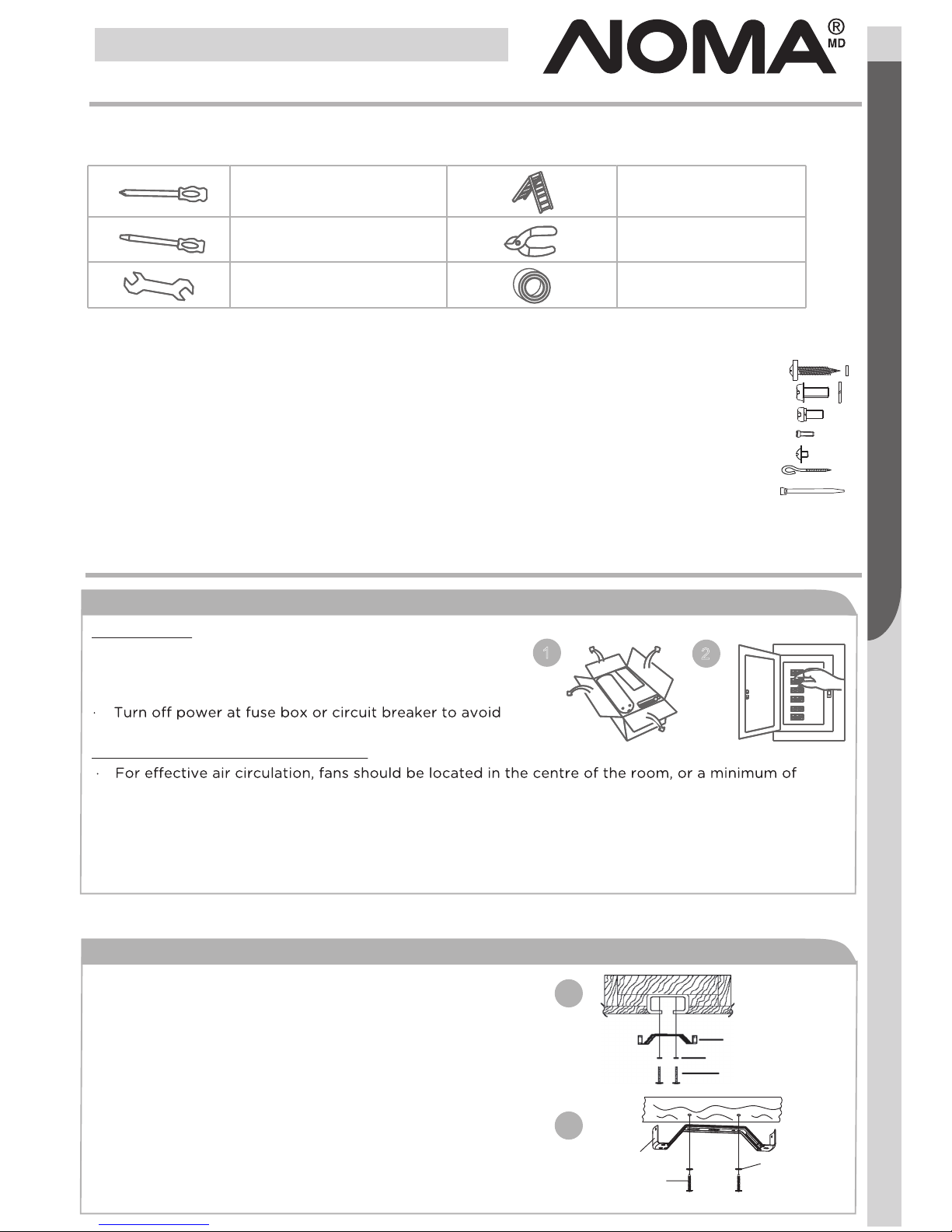
Tools Required For Assembly
This manual is designed to make it as easy as possible for you to assemble, install, operate and maintain
the ceiling fan. The following tools listed are required for assembly and installation:
1
3a
3b
2
TOOLS REQUIRED FOR ASSEMBLY
After opening the package you should find all the necessary parts for installing this ceiling fan.
The box should also contain: Parts Pack Containing:
· 5 fan blades.
· 5 decorative fan blade arms.
· 1 motor with decorative housing.
· 1 light kit with complete installation hardware.
· 3 glass shades.
· 1 mounting bracket with complete installation
hardware.
· 1 receiver and remote control with complete
installation hardware.
2 wood screws with flat washers.
2 mounting screws with lock washers.
1 extra blade bracket screws.
1 extra light kit screws.
16 Blade screws.
1 “J” hook.
2 tie wraps
ASSEMBLY
Preparing for installation
1. Mounting bracket
Getting ready
· Unpack and inspect carefully to make sure all parts are
included and not damaged (see Fig. 1). Lay all pieces out
on a working space.
possible electric shock (see Fig. 2).
Choosing a location for the ceiling fan
32" (81.3 cm) from adjacent walls or obstructions.
· Choose a location where there is a high enough ceiling clearance [at least 6’ 11” (2.1 m) from the floor
to the ceiling fan’s lowest moving part].
· Ensure that the outlet box in the room’s ceiling can support the weight of the fan. Typically, if the
outlet box is marked “acceptable for fan support”, it can hold the fan securely.
1 x star-head screwdriver
1 x flat screwdriver
1 x wrench
1 x stepladder
1 x wire stripper/pliers
1 x electrical tape
Assembly
Mounting bracket
Lock warshers
Outlet box screws
.
Normal masonry ceiling
. Securely attach the mounting bracket to an outlet box
marked “ Acceptable for Fan Support ”, using the
supplied outlet box screws with lock washers (see Fig. 3a).
Wooden ceiling
.
Drill two mounting holes in the ceiling joist.Securely
attach the mountingbracket to the wooden ceiling as
indicated below (fig. 3b).
Remove the four sets of side screws from mounting
bracket and save for future use.
Mounting
bracket
Flat
washer
wood screw
Page 6
Assembly
6
7
ASSEMBLY
2. Wiring instructions
IMPORTANT:
If you are not sure if the electrical outlet box and fan are grounded, contact
a licensed electrician for advice. They must be grounded for safe operation.
WARNING!
fuse box before wiring.
4
Toll-free: 1-866-827-4985 • model no. 052-4744-2
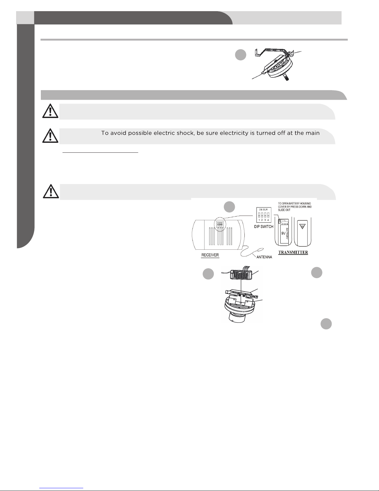
· Insert the “T” bar end of motor support bar through
rectangular opening on mounting bracket for hands free wiring and later motor assembly (see Fig. 4).
Motor support bar
Mounting bracket
4
Remote and Receiver Pairing
Receiver assembly
Position the receiver into the motor support
bar with the air holes of the receiver facing
outward and wires upward (see Fig. 5b).
Codes are set by pushing the location of the dip switches located on the transmitter and receiver
up or down. It is important that the code used for both the remote and receiver are identical for
the two devices to be able to communicate; otherwise the remote will not be able to control
the fan (see Fig. 5a).
If you plan to install more than one fan then each fan will require the remote and receive to
use a unique code, or else one remote will be able to control more than one fan.
5a
Receiver
Motor support bar
Receiver holder
5b
Making Connections
Between fan and receiver:
· Connect the black wire marked “L” from the fan to the black wire marked “TO MOTOR L” from
the receiver.
· Connect the blue wire marked “FOR LIGHT” from the fan to the blue wire marked “FOR LIGHT”
from the receiver.
· Connect the white wire marked “N” from the fan to the WHITE wire marked “TO MOTOR N” from
the receiver.
Between receiver and mains:
· Connect the black live wire marked “AC IN L” from the receiver to the live wire (typically black) from
the outlet box.
· Connect the white neutral wire marked “AC IN N” from the receiver to the neutral wire (typically
white) from the outlet box.
· Connect the green ground wires from the mounting bracket and nylon ball to the ground
wire (bare or green) from the outlet box.
Page 7

· After the splices are made, secure connectors with electrical tape. Spread the wires apart so that the
green and white wires are on one side of the outlet box and the black and blue wires are on the other.
Make sure there are no loose strands or connetions. Turn wire connectors upward and push the
wiring into the outlet box.
5
Assembly
ASSEMBLY
Note:
The silver cord is only a safety support cable to prevent the fan from falling.
Secure the steel cable to the ceiling joist with the short wood screw and flat washer
provided.
WARNING!
Be sure no bare wire or wire strands are visible after making connections. Place
green and white connections on opposite side of box from the black and blue (if applicable)
connections.
6
· Pull the black and white wires of receiver through
the centre hole of mounting bracket, then
continue the wire connections to outlet box
(see Fig. 7).
to the motor support bar ground wire. Secure the wire connection with a wire
connector provided (see Fig. 6).
Connect the black live wire marked “AC IN L” from the receiver
to the live wire (typically black) from the outlet box. Connect
the white neutral wire marked “AC IN N ” from the receiver to
the neutral wire (typically white) from the outlet box. Connect
the green ground wires from the mounting bracket and nylon
ball to the ground wire (bare or green) from the outlet box.
7
· Make sure your outlet box is grounded. Connect the ground wire (green or bare copper)
· Remove the mounting screws and washers from
the mounting bracket (see Fig. 8).
· Remove the mounting screws and washers from the
motor support bar (see Fig. 8).
· Lift motor support bar to mounting bracket.
Turn motor so "T" bar end fits through rectangular
opening on mounting bracket. Align holes and secure
with washers and screws (see Fig. 9).
8
9
3. Motor assembly
Mounting
screws
Mounting bracket
Motor suport bar
Mounting bracket
Motor suport bar
Mounting screws
Page 8
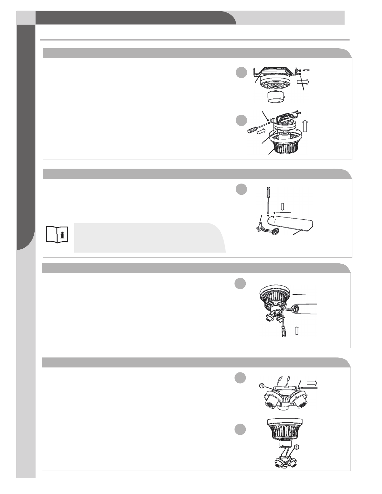
· If there are plastic tabs shaped like bottle caps, remove
and discard them. These are stabilizers that protect the
motor during shipping.
· Remove the screws on the bottom of the motor
and use them to attach the blade assembly to
the motor. Ensure the screws are tightened
(see Fig. 13).
· Remove the screws from the switch housing
cap and save for use in next step (see Fig. 14).
· Connect the wire inside the switch housing
cap by snapping the male and female
connectors together. Match white wires
together and blue wire to black wire together
(see Fig. 15).
Toll-free: 1-866-827-4985 · model no. 052-4744-2
6
Assembly
ASSEMBLY
13
6. Attach blade assembly to motor
14
15
7. Connect switch housing
Motor
Screw
· Remove the housing screws and washers from the
mounting bracket (see Fig. 10).
· Slide motor housing over motor assembly.
Secure to the sides of mounting bracket with
housing screws (see Fig. 11).
· Using the fan blade screws, attach the fan
blades to the fan blade arms with the
desired finished side faced-down on the
fan blade arms (see Fig. 12).
10
4. Motor housing assembly
Note:
This ceiling fan includes 5 dual-finished
blades. Depending on personal preference,
choose the side that best suits the decor or
furniture of your room.
11
12
5. Blade and blade bracket
Mounting bracket
Housing screws
Housing screws
Motor
Motor housing
Blade screws
Blade
Blade arm
Page 9

· Install E12 X 60 W TYPE B bulbs (not included)
(see Fig. 18).
7
ASSEMBLY
Note:
The dimmer function can not be used
if CFL bulb is used.
18
Assembly
· Attach the light kit by bringing up the
switch housing cap to the fan switch
housing.
· Then tightly secure the screws that were previously
removed from the switch housing cap (see Fig. 16).
· Unscrew the glass screw from light kit. Place neck
of glass into light housing cup. Use the star-head
screwdriver to carefully tighten the glass screws.
If too much force is used, the glass shade may
break (see Fig. 17).
16
8. Attach light kit
17
9. Attach glass shade
Switch housing
Screw
Light kit
Screw
Glass
Page 10

Forward and reverse direction function.
This ceiling fan is equipped with a reverse switch
for downward or upward air-flow.
OPERATION
20
21
Forward function
Reverse function
· On this setting, the fan will turn clockwise. Use this
function during cooler weather to re-circulate warm
air (see Fig. 21).
· On this setting, the fan will turn counter-clockwise
warmer weather to circulate hot air away from
your living space (see Fig. 20).
· Restore power to ceiling fan and test for proper operation.
· The fan remote control controls the fan settings:
HI: Turn on the fan at high speed.
MED: Turn on the fan at medium speed.
LOW: Turn on the fan at low speed.
LIGHT: ON/OFF: Press and release immediately to turn
on or on the light.
DIMMER: Press and hold on to dim or brighten
lights to the desired level and release
(only for the tungsten bulb).
LIGHT
ON/OFF
HI
MED
DIMMER
FAN OFF
LOW
Note: Do not use the reverse switch when the fan blades are in motion.
Reverse
Forward
Switch housing
Reverse switch
Toll-free: 1-866-827-4985 · model no. 052-4744-2
8
Operation
9
V
B
a
tt
e
r
y
Install the 9 V battery (not included). To prevent damage to transmitter
remove the battery if not used for long periods .
Page 11

9
Troubleshooting Maintenance
MAINTENANCE
· Because of the fan’s natural movement, some connections may become loose. Check the support
connections, brackets and blade attachments twice a year. Make sure they are secure.
· There is no need to oil your fan. The motor has permanently-lubricated bearings.
CARE AND CLEANING
· Dust your fan periodically with a soft, dry cloth. Do not use harsh cleaners or materials as they may
damage the unit.
· To prevent bending the blades during cleaning, support the blades so that no pressure is applied to
them.
Caution!
Do not allow water to come in contact with fan blades or the ceiling fan. Doing so will create
fire and /or shock hazards, damaging property.
TROUBLESHOOTING
If problems persist, seek help from a certified electrician.
Problem
Fan is noisy
during
operation
Fan does not
start
Possible reason
· Blade screws are loose.
· The mounting bracket or canopy is loose.
· Screws securing decorative housing to
hanger are loose.
· Lamp shades or bulbs are loose.
· Screws securing downrod to hanger are
loose.
· Wire connectors are vibrating against the
inside of canopy.
· Light kit or light bulb is not firmly
attached.
· Canopy is rattling against ceiling.
· Motor housing screws have come loose.
. Fuse is blown, or circuit breaker has
tripped.
. Loose or incorrect power line
connections to the fan or switch wires.
. Reverse switch is stuck in the middle.
Solution
· Tighten screws on blades with a
screwdriver.
· Check and tighten the screws.
· Check and tighten the screws.
· Tighten by hand, as necessary.
· Check and tighten screws.
· Disconnect power at fuse box, loosen
canopy and re-position connectors.
· Remove and re-attach.
· Be sure canopy is not touching ceiling.
· Check and tighten the screws.
· Check main fuse and branch circuit
fuses or circuit breaker. Repair as
necessary.
· Check all the wire connections to
fan and housing wiring. Repair as
necessary.
· Make sure reverse switch is set to one
or the other position, not stuck in the
middle.
Caution! Make sure the main
Page 12

Toll-free: 1-866-827-4985 · model no. 052-4744-2
10
Troubleshooting
Environmental Protection
TROUBLESHOOTING
Light does
not work
Fan does
not seem to
move much
air
Fan wobbles
or shakes
excessively
· Wires are not properly connected.
· Light bulbs are faulty.
· Fan is in reverse (blades are moving in
clockwise direction).
· Fan is not properly located.
· Screws securing fan blade clips to motor
are loose.
· Fan blade and its blade clip are not
fastened securely.
· Canopy and mounting bracket are not
tightened securely.
· Ensure wire connector in switch
housing is connected.
· Unscrew light bulbs and discard
properly.
· Counter-clockwise (forward) is
recommended in warm weather.
rotation to stop. Use the eraser end
of a pencil to change the forward/
reverse slide switch.
· Place fan in the centre of the room
so there is at least 12" (30 cm)
between the end of the blades and
walls or other obstructions.
. Make sure that screws which attach
fan blade clips to motor are fastened
and tightened.
. Tighten screws of fan blade to blade
clip securely.
. Ensure that canopy and mounting
bracket are tightened securely to
ceiling joist.
ENVIRONMENTAL PROTECTION
Discarded electrical appliances are recyclable and should not be discarded in your regular
domestic waste! Please actively support us in conserving resources and protecting the
environment by returning this appliance to a collection centre (if available).
Battery reclamation (please keep to comply with the local law).
Problem
Possible reason
Solution
Page 13

11
Warranty
This Noma product carries a limited ten (10) year warranty against defects in the motor, and a one (1)
year warranty against defects in workmanship and materials. Noma Canada agrees to replace the
defective product free of charge within the stated warranty period, when returned by the original
purchaser with proof of purchase. This product is not guaranteed against wear or breakage due to
misuse and/or abuse.
Made in China
Imported by
Noma Canada, Toronto, Canada M4S 2B8
Subject to the conditions and limitations described below, this product, if returned to us with proof of
purchase within the stated warranty period and if covered under this warranty, will be repaired or
replaced (with the same model, or one of equal value or specification), at our option. We will bear the
cost of any repair or replacement and any costs of labor relating thereto.
These warranties are subject to the following conditions and limitations:
a) A bill of sale verifying the purchase and purchase date must be provided;
b) This warranty will not apply to any product or part thereof which is worn or broken or which has
become inoperative due to abuse, misuse, accidental
installation,
damage, neglect or lack of proper
o peration or maintenance (as outlined in the applicable owner’s manual or operating
instructions)
or which is being used for industrial, professional , commercial or rental purposes;
c) This warranty will not apply to normal wear and tear or to expendable parts or accessories that
may be supplied with the product that are expected to become inoperative or unusable after a
reasonable period of use;
d) This warranty will not apply to routine maintenance and consumable items such as, but not limited
to, fuel, lubricants, vacuum bags, blades, belts, sandpaper, bits, fluids, tune-ups or adjustments;
e) This warranty will not apply where damage is caused by repairs made or attempted by others
(i.e. persons not authorized by the manufacturer);
f) This warranty will not apply to any product that was sold to th e original purchaser as a
reconditioned or refurbished product (unless otherwise specified in writing);
g) This warranty will not apply to any product or part thereof if any part from another manufacturer
is installed therein or any repairs or alterations have been made or attempted by unauthorized
persons;
h) This warranty will not apply to normal deterioration of the exterior finish, such as, but not limited
to, scratches, dents, paint chips, or to any corrosion or discoloring by heat, abrasive and chemical
cleaners; and
i) This warranty will not apply to component parts sold by and identified as the product of another
company, which shall be covered under the product manufacturer’s warranty, if any.
Additional Limitations
This warranty applies only to the original purchaser and may not be transferred. Neither the retailer nor
the manufacturer shall be liable for any other expense, loss or damage, including, without limitation,
any indirect, incidental, consequential or exemplary damages arising in connection with the sale, use or
inability to use this product.
Notice to Consumer
This warranty gives you specific legal rights, and you may have other rights, which may vary from
province to province. The provisions contained in this warranty are not intended to limit, modify, take
away from, disclaim or exclude any statutory warranties set forth in any applicable provincial or
federal legislation
Page 14

VENTILATEUR DE
PLAFOND TUSCAN
Guide d’utilisation
IMPORTANT :
Veuillez lire et bien comprendre ce guide avant de procéder à l’assemblage.
Numéro sans frais : 1 866 827-4985
N° de modèle : 052-4744-2
Avant de procéder à l’assemblage du produit, assurez-vous que toutes les pièces sont présentes.
Comparez les pièces à la vue éclatée. S’il manque des pièces, ou si vous avez des questions,
communiquez avec le service à la clientèle en composant le 1 866 827-4985 (numéro sans frais).
V.4 2016
Page 15

IMPORTANT: RETAIN FOR FUTURE REFERENCE, AND READ CAREFULLY
Numéro sans frais : 1 866 827-4985 · N° de modèle : 052-4744-2
Vue éclatée ................................................................................................................. 1
Consignes de sécurité importantes........................................................................... 2
Règles pour une installation en toute sécurité ..................................................... 2
Outils requis pour l'assemblage ................................................................................ 3
Assemblage ........................................................................................................................... 3
Fonctionnement ..................................................................................................................... 7
Entretien ..................................................................................................................... 8
Dépannage ................................................................................................................. 8
Protection de l'environnement ................................................................................. 9
Garantie ............................................................................................................................. 10
Table des matières
IMPORTANT : CONSERVEZ CE GUIDE AUX FINS DE CONSULTATION ULTÉRIEURE,
ET LISEZ-LE ATTENTIVEMENT.
Table des matières
Page 16

Vue éclatée
1
VUE ÉCLATÉE
N° Description Qté
A
C
B
1
1
1
1
5
5
3
1
1
1
Support de montage
Support du récepteur
Barre de support
du moteur
Moteur
Boîtier du moteur
Pale
Ensemble d’éclairage
Abat-jour en verre
Récepteur
Télécommande
Support de pale
1
1
1
Sac de pièces
D
B
C
D
E
F
G
H
I
J
K
L
M
A
E
G
F
H
I
J
K
L
N° Description Qté
M
Page 17

Numéro sans frais : 1 866 827-4985 · N° de modèle : 052-4744-2
2
.
Consignes de sécurité importantes
CONSIGNES DE SÉCURITÉ IMPORTANTES
Conservez ce guide aux fins de consultation ultérieure.
Remarque :
sur le ventilateur de plafond.
• Un chion sec convient pour la plupart des nettoyages;
• Si le ventilateur de plafond devient humide, confiez son inspection à un électricien qualifié avant de
l’utiliser ultérieurement;
• Les réparations du ventilateur de plafond doivent être eectuées par une personne qualifiée afin de se
conformer aux règlements de sécurité et d’éviter les risques d’accident;
• Faites attention aux pales lorsque vous nettoyez, peignez ou travaillez à proximité du ventilateur de
plafond;
• Les enfants ne peuvent pas identifier les dangers qui peuvent survenir pendant le fonctionnement du
ventilateur de plafond. Tenez les enfants éloignés du ventilateur de plafond.
NE FAITES PAS CE QUI SUIT :
• Exposer le ventilateur de plafond à l’eau ou l’immerger dans l’eau;
• Faire fonctionner le ventilateur de plafond s’il montre des signes d’endommagement ou s’il est tombé;
• Tenter de retirer une pièce du boîtier ou introduire un objet lorsque le ventilateur de plafond est en marche;
• Positionner le ventilateur de plafond sur ou près de surface
s chaudes telles qu’une table de cuisson ou
près de flammes nues;
• Exposer le ventilateur de plafond à la pluie ou l’humidité;
• Faire fonctionner le ventilateur de plafond à l’extérieur ou avec les mains mouillées;
• Utiliser le bouton marche avant/arrière lorsque les pales du ventilateur sont en mouvement. Ceci pourrait
endommager le ventilateur de plafond.
RÈGLES POUR UNE INSTALLATION EN TOUTE SÉCURITÉ
Le ventilateur de plafond est conçu pour une utilisation domestique seulement et non pour des applications
commerciales. Nous ne saurions être tenus responsables des dommages résultant d’une utilisation non
conforme aux instructions ou du non-respect des instructions.
ATTENTION!
• Pour éviter tout risque de choc électrique, veillez à couper l’alimentation au tableau de
distribution ou au boîtier de disjoncteurs avant de procéder au câblage.
• Le câblage doit être eectué conformément aux codes de câblage nationaux et locaux.
Consultez un électricien qualifié pour déterminer si vous avez le bon conducteur de circuit
de dérivation.
• Suivez les recommandations fournies pour câbler correctement votre nouveau ventilateur de
plafond. Le ventilateur de plafond doit être relié à la terre par mesure de précaution contre
les risques de choc électrique.
• La boîte de sortie électrique et la solive de plafond doivent être solidement fixées et capables
de supporter de manière fiable au moins 35 lb (15,9 kg).
• Montez les pièces mobiles les plus basses à au moins 6 pi 11 po (2,1 m) au-dessus du sol.
• Assurez-vous que toutes les connexions électriques sont bien scellées au moyen de
capuchons de connexion et de ruban isolant appropriés à l’intérieur de la boîte de sortie
électrique.
• Assurez-vous que le ventilateur de plafond est solidement fixé au plafond.
• Toutes les vis de fixation doivent être vérifiées et resserrées si nécessaire avant de faire
fonctionner le ventilateur.
• Si vous ne possédez pas de connaissances susantes en matièr e de câblage électrique,
confiez l’installation du ventilateur à un électricien qualifié.
AVERTISSEMENT!
• Le montage ne doit être eectué que sur une boîte de sortie électrique portant la mention
« Acceptable for Fan Support » (peut supporter un ventilateur).
• Pour éviter les blessures, assurez-vous que les pales du ventilateur ne sont pas cintrées et
qu’il n’y a pas d’objets dans la zone de rotation.
• Les importantes mises en garde et directives contenues dans ce guide ne couvrent pas de
façon exhaustive toutes les situations possibles. L’utilisateur doit comprendre que le bon sens
et la prudence sont des facteurs qui ne peuvent pas être intégrés à ce produit.
• Ne doit pas être utilisé avec une commande de vitesse à semi-conducteurs.
Règles pour une installation en toute sécurité
Page 18

INSTALLATION
3
Outils requis pour l’assemblage
Ce guide est conçu pour vous aider à facilement assembler, installer, faire fonctionner et entretenir le
ventilateur de plafond. Les outils suivants sont nécessaires à l’assemblage et à l’installation :
3a
3b
OUTILS REQUIS POUR L’ASSEMBLAGE
À l’intérieur de l’emballage, vous devriez trouver toutes les pièces nécessaires à l’installation du
ventilateur de plafond. La boîte devrait aussi contenir : Le sac de pièces contient :
· 5 pales de ventilateur.
· 5 supports décoratifs de pale
· 1 moteur avec boîtier décoratif.
· 1 ensemble de luminaires avec quincaillerie
d’installation au complet.
· 3 abat-jour en verre.
· 1 support de montage avec quincaillerie
d’installation au complet.
· 1 récepteur et 1 télécommande avec quincaillerie
d’installation au complet.
2 vis à bois avec rondelles plates.
2 vis de montage avec rondelles
de blocage..
1 vis supplémentaire pour support
de pale.
1 vis supplémentaire pour ensemble
d’éclairage
16 vis de pale.
1 crochet en « J ».
2 attache à tête d’ équerre
ASSEMBLAGE
1. Support de montage
1 x tournevis à tête cruciforme
1 x tournevis à tête plate
1 x clé
1 x escabeau
1 x pince à dénuder
1 x ruban isolant
Assemblage
Mounting bracket
Lock warshers
Outlet box screws
.
Plafond en plâtre ordinaire
. Fixez solidement le support de montage à mention
« Acceptable for Fan Support » (peut supporter
un ventilateur), au moyen des vis et rondelles de
blocage fournies vec la boîte de sortie électrique.
(voir fig. 3a).
Plafond en bois
. Percez deux trous de montage dans la solive
du plafond. Fixez solidement le support de
montage au plafond, au moyen de deux longues
vis à bois avec des rondelles plates.(voir fig. 3b).
Retirez les quatre ensembles de vis latéralesavec les
du socle et conservez-les pour uneutilisation ultérieure.
Mounting
bracket
Flat
washer
wood screw
1
2
Préparation de l’installation
Au préalable
• Déballez et inspectez soigneusement toutes les pièces
pour vous assurer qu’elles sont toutes incluses et non
endommagées (voir figure 1). Disposez toutes les pièces
sur une surface de travail.
• Coupez l’alimentation électrique sur le panneau électrique ou au
boîtier de disjoncteurs pour éviter tout choc électrique (voir figure 2).
Choisir un emplacement pour le ventilateur de plafond
• Pour ventiler ecacement, le ventilateur doit être situé au centre de la pièce ou à une distance d’au
moins 32 po (81,3 cm) des murs adjacents ou obstacles.
• Choisissez un emplacement où il y a susamment de dégagement sous le plafond [au moins 6 pi 11
po (2,1 m) à partir du sol jusqu’aux pièces mobiles les plus basses du ventilateur de plafond].
• Assurez-vous que la boîte de sortie électrique située dans le plafond de la pièce peut supporter le
poids du ventilateur. Normalement, la boîte de sortie électrique doit porter la mention « Acceptable
for Fan Support » (peut supporter un ventilateur).
Page 19

Assemblage
6
7
ASSEMBLY
2. Instructions de câblage
IMPORTANT:
à la terre, consultez un électricien qualifié. Ils doivent être reliés à la terre pour un
fonctionnement en toute sécurité.
Si vous ne savez pas si la boîte de sortie électrique et le ventilateur sont reliés
AVERTISSEMENT :
Pour éviter tout risque de choc électrique, assurez-vous que l’alimentation
est coupée sur le panneau électrique ou au boîtier de disjoncteurs avant de procéder au câblage .
.
4
Numéro sans frais : 1 866 827-4985 · N° de modèle : 052-4744-2
· Insérez l’extrémité en « T » de la barre de support du
moteur dans l’ouverture rectangulaire du support
de montage pour pouvoir réaliser le câblage et
ultérieurement l’assemblage du moteur à mains libres
(voir figure 4).
Barre de support
du moteur
Support de
montage
4
Coupler la télécommande au récepteur
Assemblage du récepteur
Insérez le récepteur dans la barre de support
du moteur avec les trous d’aération du
récepteur orientés vers l’extérieur et les fils
orientés vers le haut (voir figure 5a).
Les codes sont établis en poussant vers le haut ou vers e bas les commutateurs DIP situés sur le
transmetteur et le récepteur. Il est important d'utiliser le même code pour la télécommande et le
récepteur afin que ces deux appareils puissent communiquer; sinon, la télécommande ne pourra
pas commander le ventilateur(voir fig. 5a).
Si vous songez à installer plus d'un ventilateur, chaque ven tilateur doit utiliser un code unique
pour la télécommande et le récepteur;autrement, une seule télécommande contrôlera tous
les ventilateurs.
5a
Récepteur
Barre de support du moteur
Support du récepteur
5b
Raccordements
Entre le ventilateur et le récepteur :
· Raccordez le fil noir marqué « L » (sous tension) du ventilateur au fil noir marqué « TO MOTOR
L » (conducteur de phase pour moteur) du récepteur.
· Raccordez le fil bleu marqué « FOR LIGHT » (pour lumière) du ventilateur au fil bleu marqué
« FOR LIGHT » (pour lumière) du récepteur.
· Raccordez le fil blanc marqué « N » (neutre) du ventilateur au fil BLANC marqué « TO MOTOR
N » (conducteur neutre pour moteur) du récepteur.
Entre le récepteur et la boîte de sortie électrique :
· Raccordez le fil sous tension noir marqué « AC IN L » (conducteur de phase) du récepteur au fil
sous tension (normalement noir) de la boîte de sortie électrique.
· Raccordez le fil neutre blanc marqué « AC IN N » (conducteur neutre) du récepteur au fil neutre
(normalement blanc) de la boîte de sortie électrique.
· Raccordez les fils de terre verts du support de montage et de la boule en nylon au fil de terre
(nu ou vert) de la boîte de sortie électrique.
Page 20

· Une fois toutes les jonctions de fils eectuées, fixez les connecteurs à l’aide de ruban isolant. Écartez
les fils les uns des autres de façon à ce que les fils vert et blanc se trouvent d’un côté de la boîte de
sortie électrique et les fils noir et bleu de l’autre côté. Assurez-vous qu’aucun brin de fil ou
branchement n’est desserré. Tournez les connecteurs de fils vers le haut et repoussez le câblage à
l’intérieur de la boîte de sortie électrique.
5
Assemblage
Assemblage
Remarque :
tomber. Fixez solidement le câble de sécurité à la solive du plafond au moyen de la vis à bois
courte et de la rondelle plate fournies.
Le cordon argenté n’est qu’un câble de sécurité pour empêcher le ventilateur de
AVERTISSEMENT!
Assurez-vous qu’aucun fil nu ou brin de fil n’est visible après avoir
eectué tous les raccordements. Placez les raccordements vert et blanc du côté opposé
aux raccordements noir et bleu (le cas échéant) dans la boîte de sortie électrique.
6
· Faites passer les fils noir et blanc du récepteur
dans le trou central du support de montage,
puis poursuivez les branchements de fils à la boîte
de sortie électrique (voir figure 7).
Raccordez le fil sous tension noir marqué « AC IN L » (conducteur
de phase) du récepteur au fil sous tension (normalement noir) de
la boîte de sortie électrique. Raccordez le fil neutre blanc marqué
« AC IN N » (conducteur neutre) du récepteur au fil neutre
(normalement blanc) de la boîte de sortie électrique. Raccordez
les fils de terre verts du support de montage et de la boule en nylon
au fil de terre (nu ou vert) de la boîte de sortie électrique.
7
· Assurez-vous que votre boîte de sortie électrique est reliée à la terre. Branchez le fil de terre (vert ou
cuivre nu) au fil de terre de la barre de support du moteur. Fixez le branchement de fils au moyen du
capuchon de connexion fourni (voir figure 6).
· Retirez les vis de montage et les rondelles du support de
montage (voir figure 8).
· Retirez les vis de montage et les rondelles de la barre de
support du moteur (voir figure 8).
· Levez la barre de support du moteur vers le support de
montage. Tournez le moteur de sorte que l’extrémité de
la barre en « T » entre dans l’ouverture rectangulaire du
support de montage. Alignez les trous et fixez l’ensemble
au moyen des rondelles et des vis (voir figure 9).
8
9
3. Assemblage du moteur
Vis de
montage
Support de montage
Barre de support
du moteur
Support de montage
Barre de support
du moteur
Vis de montage
Boîte de sortie électrique
(Fils d’alimentation)
Fil de terre
Fil de terre vert du support
de montage et de la boule
CONDUCTEUR
DE PHASE
CONDUCTEUR
NEUTRE
CONDUCTEUR
NEUTRE POUR
MOTEUR
CONDUCTEUR
DE PHASE
POUR MOTEUR
POUR LUMIÈRE
N
L
POUR
LUMIÈRE
Page 21

· S’il y a des languettes en plastique en forme de capsule pour
bouteille, retirez-les et jetez-les. Ceux-ci sont des stabilisateurs
qui protègent le moteur lors de l’expédition.
· Retirez les vis au bas du moteur et utilisez-les pour fixer l’assemblage
de pale au moteur. Assurez-vous que les vis sont bien serrées
(voir figure 13).
· Retirez les vis de la monture du coret d’interrupteur
et conservez-les pour la prochaine étape (voir figure 14).
· Raccordez le fil à l’intérieur de la monture du coret
d’interrupteur en enclenchant ensemble les connecteurs
mâle et femelle. Branchez le fil blanc avec le fil blance
et le fil blance et le fil bleu avec le fil noir.(voir figure 15).
Numéro sans frais : 1 866 827-4985 · N° de modèle : 052-4744-2
6
Assemblage
Assemblage
13
6. Fixation de l’assemblage de pale au moteur
14
15
7. Raccordement du coret d’interrupteur
Moteur
Vis
· Retirez les vis et les rondelles pour boîtier du moteur du
support de montage (voir figure 10).
· Faites coulisser le boîtier du moteur par-dessus le bloc
moteur. Fixez les bords du support de montage au moyen
des vis pour boîtier de moteur (voir figure 11).
· Au moyen des vis pour pales, fixez les pales du
ventilateur aux supports de pales en vous assurant
que le côté avec le revêtement désiré est orienté
vers le bas sur le support de pale (voir figure 12).
10
4. Assemblage du boîtier du moteur
Remarque :
pales à double revêtement. Selon vos préférences
personnelles, choisissez le côté qui convient mieux à
votre décor ou vos meubles de la pièce.
Le ventilateur de plafond comprend 5
11
12
5. Pales et supports de pales
Vis
Support de montage
Vis pour boîtier de moteur
Moteur
Boîtier de moteur
Vis
Pale
Support de pale
Page 22

· Installez E12 X 60 W TYPE B ampoules (non comprises)
(voir figure 18).
7
Assemblage
Remarque :
utilisée, le gradateur ne fonctionne pas.
Si une ampoule fluocompacte est
18
Assemblage
· Fixez l’ensemble d’éclairage en posant la monture du
coret d’interrupteur sur le coret d’interrupteur du
ventilateur.
· Serrez ensuite les vis qui ont été retirées précédemment
de la monture du coret d’interrupteur (voir figure 16).
· Dévissez la vis de l’abat-jour en verre de l’ensemble
d’éclairage. Placez le cou de l’abat-jour dans la coupelle
d’éclairage. Utilisez le tournevis à tête cruciforme pour serrer
soigneusement les vis de l’abat-jour en verre. Une trop forte
pression pourrait briser le verre (voir figure 17).
16
8. Fixation de l’ensemble d’éclairage
17
9. Fixation de l’abat-jour en verre
Coret d’interrupteur
Vis
Ensemble d’éclairage
Vis
Ensemble d’éclairage
Page 23

FONCTIONNEMENT
Numéro sans frais : 1 866 827-4985 · N° de modèle : 052-4744-2
8
FONCTIONNEMENT
9
V
B
a
tt
e
r
y
Rétablissez l’alimentation du ventilateur de plafond et testez son
fonctionnement.
Installez la pile de 9 V (non comprise). Pour éviter d'endommager l'émetteur,
retirez la pile s'il n'est pas utilisé pendant de longues périodes.
20
Fonction Marche avant
• Avec ce réglage, le ventilateur tourne en sens antihoraire pour
créer un eret de refroidissement. Utilisez cette fonction en été
pour faire circuler l’air chaud de manière ascendante et l’éloigner
de votre espace de vie (voir figure 20).
Marche/arrêt et sélection de vitesse du ventilateur
• Rétablissez l'alimentation du ventilateur de plafond et
testez-le pour le bon fonctionnement.
• La chaînette du ventilateur commande les réglages de
vitesse du ventilateur :
ARRÊT : appuyer sur ce bouton arrête le ventilateur.
ÉLEVÉE : appuyer sur ce bouton met le ventilateur en marche
à vitesse élevée.
MOY : appuyer sur ce bouton met le ventilateur en marche à
vitesse moyenne.
BASSE : appuyer sur ce bouton met le ventilateur en marche à
vitesse basse.
DE LA LUMIÈRE : appuyer et relâcher immédiatement sur ce
bouton allume ou éteint la lumière.
GRADATEUR : appuyer sur ce bouton et le maintenir enfoncé réduit
ou augmente l'intensité d'éclairage et le relâcher verrouille
l'intensité d'éclairage au niveau désiré (fonctionne seulement
pour les ampoules à filament de tungstène).
MARCHE/ARRÊT
MARCHE/ARRÊT
DE LA LUMIÈRE
ÉLEVÉ
MOY
GRADATEUR
ARRÊT DU
VENTILATEUR
BASSE
Remarque : N'utilisez pas le bouton marche avant/arrière lorsque les pales du
ventilateur sont en mouvement.
Inversion du sens de rotation du ventilateur
Le ventilateur de plafond est doté d'un bouton
marche avant/arrière pour faire
circuler l'air vers le haut ou vers le bas.
Marche arrière
Marche avant
Coret d’interrupteur
Bouton marche
avant/arrière
21
Fonction Marche arrière
• Avec ce réglage, le ventilateur tourne en sens horaire. Utilisez
cette fonction en hiver pour faire circuler l’air chaud
(voir figure 21).
Page 24

9
Dépannage Entretien
ENTRETIEN
• En raison du mouvement naturel du ventilateur, des connexions peuvent se desserrer. Vérifiez les
connexions, les supports et les raccordements des pales deux fois par an. Assurez-vous qu’ils sont bien
serrés.
ENTRETIEN ET NETTOYAGE
• Époussetez votre ventilateur régulièrement à l’aide d’un chion doux et sec. N’utilisez pas de nettoyants
puissants ni de matériaux abrasifs, car ils peuvent endommager le ventilateur.
• Pour éviter de cintrer les pales lors du nettoyage, soutenez-les de façon à n’exercer aucune pression.
Attention!
Ne laissez pas l’eau entrer en contact avec les pales ou le ventilateur de plafond. L’eau pourrait
créer des risques d’incendie ou de choc entraînant des dommages aux biens.
DÉPANNAGE
Si les problèmes persistent, contactez un électricien qualifié.
Problème
Le ventilateur
fait du bruit
lorsqu’il tourne
Cause possible
Solution
• Assurez-vous que le bouton de marche
avant/arrière est réglé sur une de ces
deux positions et qu’il ne se trouve pas
coincé au milieu.
• Il n’est pas nécessaire de lubrifier votre ventilateur. Les roulements du moteur sont lubrifiés en
permanence.
• Les vis du ventilateur sont desserrées.
• Le support de montage ou le socle est
desserré.
• Les vis fixant le boîtier décoratif au support
de montage sont desserrées.
• Les abat-jour ou les ampoules sont
desserrés.
• Les vis fixant le tube au support sont
desserrées.
• Les capuchons de connexion vibrent contre
l’intérieur du socle.
• L’ensemble d’éclairage ou les ampoules ne
sont pas solidement fixés.
• Le socle fait un bruit de cliquetis contre le
plafond.
• Les vis du boîtier du moteur sont
desserrées.
• Serrez les vis sur les pales à l’aide d’un
tournevis.
• Vérifiez et serrez les vis.
• Vérifiez et serrez les vis.
• Serrez à la main, au besoin.
• Vérifiez et serrez les vis.
• Coupez l’alimentation sur le panneau
électrique, desserrez le socle et
repositionnez les capuchons de
connexion.
• Retirez-les et fixez-les à nouveau.
• Assurez-vous que le socle ne touche pas
le plafond.
• Vérifiez et serrez les vis.
.
Le ventilateur
ne démarre
pas.
• Le fusible est grillé ou le disjoncteur est
déclenché.
• Les raccordements des fils d’alimentation
au ventilateur ou au commutateur sont
desserrés ou incorrects.
• Le bouton de marche avant/arrière est
coincé au milieu.
• Vérifiez le fusible ou le disjoncteur du
circuit sur le panneau électrique ou au
boîtier de disjoncteurs.
• Réparez au besoin.
• Vérifiez toutes les connexions au
ventilateur et le câblage du boîtier.
Réparez au besoin.
Attention! Assurez-vous que
l’alimentation sur le panneau
électrique est coupée.
Page 25

Numéro sans frais : 1 866 827-4985 · N° de modèle : 052-4744-2
10
.
Dépannage
Protection De L'environnementé
DÉPANNAGE
PROTECTION DE L'ENVIRONNEMENT
Problème
Cause possible
Solution
Le luminaire
ne s'allume
pas
Le ventilateur
ne déplace
pas beaucoup
d'air
Le ventilateur
oscille ou
secousse
excessivement
• Les fils ne sont pas bien connectés.
• Les ampoules sont défectueuses.
• Le ventilateur est en mode inversé (les
pales tournent en sens horaire).
• Le ventilateur n’est pas convenablement
placé.
• Les vis fixant les pinces des pales du
ventilateur au moteur sont desserrées.
• La pale du ventilateur et sa pince ne sont
pas bien fixées.
• Le socle et le support de montage ne sont
pas bien serrés.
• Assurez-vous que le capuchon de
connexion dans le coret d’interrupteur
est bien fixé.
• Dévissez les ampoules et jetez-les de
façon appropriée.
• La rotation en sens antihoraire (marche
avant) est recommandée en été.
Éteignez le ventilateur et coupez
l’alimentation, puis attendez que les
pales arrêtent de tourner. Utilisez le
bout de gomme à eeacer d’un crayon
pour déplacer le bouton de marche
avant/arrière.
• Installez le ventilateur au centre de la
pièce de sorte que les extrémités des
pales se trouvent à une distance d’au
moins 12 po (30 cm) des murs ou
autres obstacles.
• Assurez-vous que les vis qui attachent
les pinces des pales du ventilateur au
moteur sont bien fixées et serrées
• Serrez solidement les vis des pales du
ventilateur aux pinces des pales.
• Veillez à ce que le socle et le support
de montage soient solidement fixés à la
solive du plafond.
Les appareils électriques usagés sont recyclables et ne doivent pas être jetés avec les déchets
ménagers ordinaires. Veuillez participer activement à la conservation des ressources et à la
protection de l’environnement en retournant cet appareil à un centre de recyclage (s’il en existe
un près de chez vous).
Recyclage des piles (conservez-les et assurez-vous de respecter la loi municipale).
Page 26

11
Garantie
GARANTIE
Cet article Noma comprend une garantie de dix (10) ans contre toute défectuosité du moteur et une garantie
de un (1) an contre les défauts de fabrication et de matériau(x). Noma Canada consent à remplacer l’article
défectueux sans frais au cours de la période de garantie convenue lorsque l’article, accompagné de la
preuve d’achat, est retourné par l’acquéreur initial. Exclusion : usure ou bris causés par un usage abusif ou
inapproprié.
Sous réserve des conditions et restrictions décrites ci-dessous, ce produit, s’il nous est retourné accompagné
de la preuve d’achat durant la période de garantie définie et qu’il est protégé en vertu de cette garantie, sera
réparé ou remplacé, à notre gré, par le même modèle ou un modèle de valeur égale ou ayant les mêmes
caractéristiques. Nous assumerons le coût de tout remplacement ou réparation ainsi que les frais de
main-d’œuvre s’y rapportant.
La présente garantie est assujettie aux conditions et restrictions qui suivent :
a) un contrat de vente attestant l’achat et la date d’achat doit être fourni;
b) la présente garantie ne s’applique à aucun produit ou pièce d’un produit qui est usé ou brisé, qui est
devenu hors d’usage en raison d’un emploi abusif ou inapproprié, d’un dommage accidentel, d’une
négligence ou d’une installation, d’une utilisation ou d’un entretien inapproprié (selon la description
figurant dans le guide d’utilisation ou le mode d’emploi applicable) ou qui est utilisé à des fins industrielles,
professionnelles, commerciales ou locatives;
c) la présente garantie ne s’applique pas à l’usure normale ou aux pièces ou accessoires non réutilisables qui
sont fournis avec le produit et qui deviendront vraisemblablement inutilisables ou hors d’usage après une
période d’utilisation raisonnable;
d) la présente garantie ne s’applique pas à l’entretien régulier et aux articles de consommation incluant sans
s’y limiter, le carburant, les lubrifiants, les sacs d’aspirateurs, les lames, les courroies, le papier abrasif, les
embouts, les liquides, les mises au point ou les réglages;
e) la présente garantie ne s’applique pas lorsque les dommages sont causés par des réparations ou des
tentatives de réparation faites par des tiers (c’est-à-dire des personnes non autorisées par le fabricant);
f) la présente garantie ne s’applique à aucun produit qui a été vendu à l’acheteur original à titre de produit
remis en état ou remis à neuf (à moins qu’il n’en soit prévu autrement par écrit);
g) la présente garantie ne s’applique à aucun produit ou pièce de produit lorsqu’une pièce d’un autre
fabricant est installée dans celui-ci ou que des réparations ou modifications ou tentatives de réparation
ou de modification ont été faites par des personnes non autorisées;
h) la présente garantie ne s’applique pas à la détérioration normale du fini extérieur, notamment les
éraflures, les bosses et les éclats de peinture, ou à la corrosion ou à la décoloration causée par la chaleur,
les produits abrasifs et les produits de nettoyage chimiques; et
i) la présente garantie ne s’applique pas aux pièces vendues par une autre entreprise et décrites comme
telles, lesquelles pièces sont couvertes par la garantie du fabricant s’y rapportant, le cas échéant.
Restrictions supplémentaires
La présente garantie s’applique uniquement à l’acheteur original et ne peut être transférée. Ni le détaillant
ni le fabricant n’est responsable des autres frais, pertes ou dommages, incluant sans s’y limiter, les dommages
indirects, accessoires ou exemplaires liés à la vente ou à l’utilisation du présent produit ou à l’impossibilité
de l’utiliser.
Avis au consommateur
La présente garantie vous accorde des droits précis et il se peut que vous ayez d’autres droits, lesquels
peuvent varier d’une province à l’autre. Les dispositions énoncées dans la présente garantie ne visent pas
à modifier, à restreindre, à éliminer, à rejeter ou à exclure les garanties énoncées dans les lois fédérales ou
provinciales applicables.
Fabriqué en Chine
Importé par
Noma Canada, Toronto, Canada M4S 2B8
 Loading...