

NOMA 052-1196-4 Instruction Manual
READ AND SAVE THESE INSTRUCTIONS
052-1196-4
Alabaster 42" (106.7 cm) Ceiling Fan
Instruction Manual

2
Warning: To reduce the risk of personal injury, do not bend the blade arms (also referred to as flanges), when installing the brackets,
balancing the blades, or cleaning the fan. Do not insert foreign objects between rotating fan blades.
Warning: To reduce the risk of fire, electric shock or personal injury, mount fan to outlet box marked "acceptable for fan support" with
the screws provided with the outlet box.
Safety Rules–Read and Save These Instructions
1. To reduce the risk of electric shock, ensure electricity has been turned off at the circuit breaker or fuse box before installing.
2. All wiring must be in accordance with the national and local electrical codes. Electrical installation should be performed by a
qualified licensed electrician.
3. WARNING: To reduce the risk of electrical shock or fire, do not use this fan with any solid-state fan-speed control device. It will
permanently damage the electronic circuitry.
4. CAUTION: To reduce the risk of personal injury, use only the screws provided with the outlet box.
5. The outlet box and support structure must be securely mounted and capable of reliably supporting a minimum of 35 lb (15.9 kg).
Use only UL listed outlet boxes marked “FOR FAN SUPPORT.”
6. The fan must be mounted with a minimum of 7' (2.13 m) from the trailing edge of the blades to the floor.
7. Avoid placing objects in the path of the blades.
8. To avoid personal injury or damage to the fan and other items, be cautious when working around or cleaning the fan.
9. Do not use water or detergents when cleaning the fan or fan blades. A dry dust cloth or lightly-dampened cloth will be suitable for
most cleaning.
10. After making electrical connections, spliced conductors should be turned upward and pushed carefully up into the outlet box. The
wires should be spread apart with the grounded conductor and the equipment-grounding conductor on one side of the outlet box
and the ungrounded conductor on the other side of the outlet box.
11. All set screws must be checked and retightened where necessary before installation.
Warning: To reduce the risk of fire, electric shock, or personal injury, mount to outlet box marked "acceptable for fan support of 35 lb
(15.9 kg) or less" and use mounting screws provided with the outlet box. Most outlet boxes commonly used for the support of light
fixtures are not acceptable for fan support and may need to be replaced. Due to the complexity of the installation of this fan, a qualified,
licensed electrician is strongly recommended.
!
!
!
Attention: This product is equipped with a 190 W limiting device. If lamping exceeds 190 W the light kit will shut off automatically
until the proper wattage of bulbs is installed. Reset the light kit by turning it off, replacing the bulbs with the correct wattage, and then
turning the light kit back on.
!
Required
Helpful
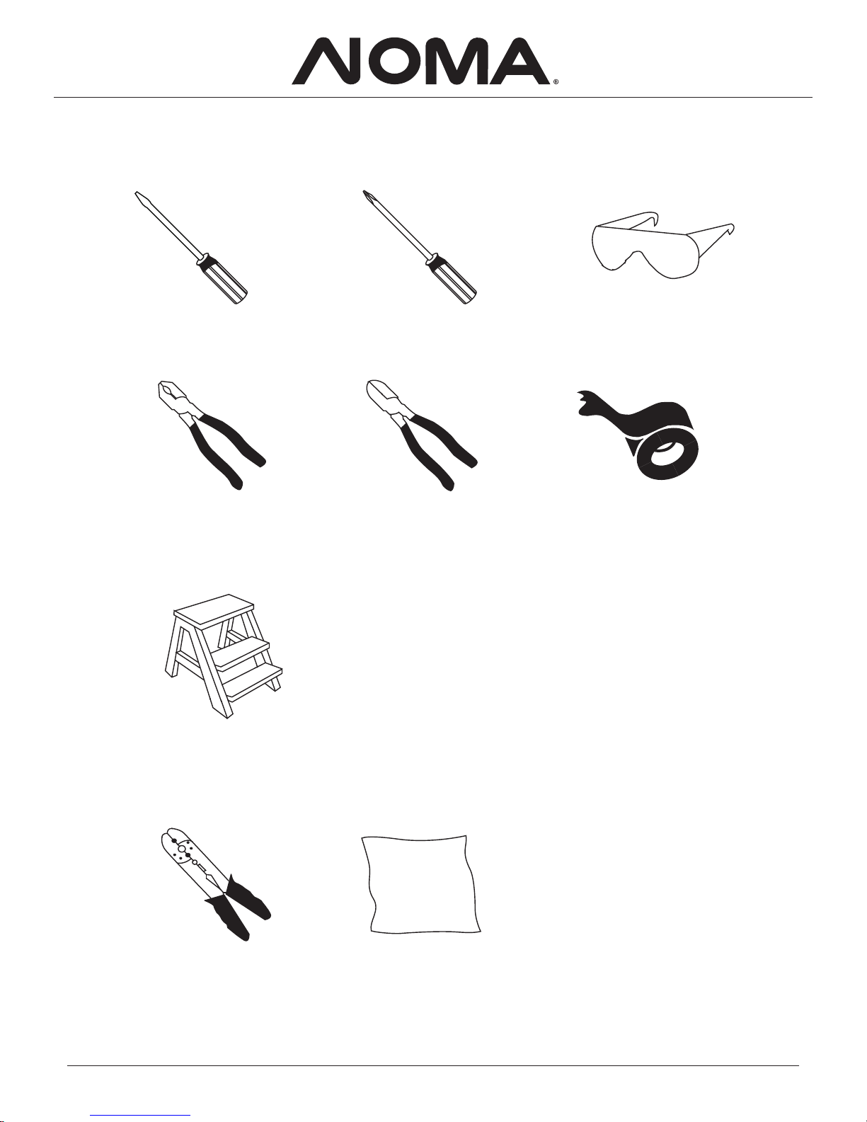
Flathead
screwdriver
Crosshead
screwdriver
Safety glasses
Pliers
Step ladder
Wire strippers
Wire cutters
Soft cloth
Electrical t ape
Tools Needed (not supplied)
3
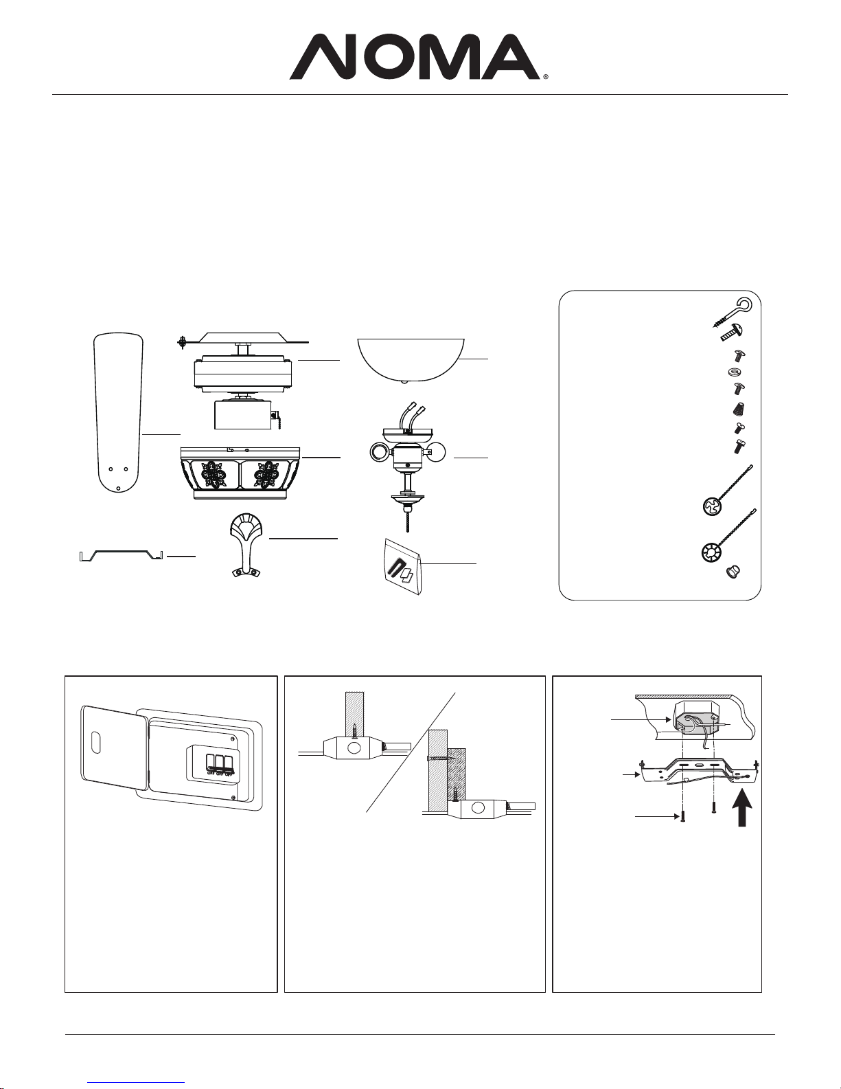
Unpacking Your Fan
Unpack and inspect fan carefully to be certain all contents are included.
Turn off power at breaker box to
avoid possible electric shock.
Use metal outlet box (sold separately)
suitable for fan support. Secure outlet box
directly to the building structure using wood
screws (included). Outlet box must support
35 lb (15.9 kg) minimum.
Install mounting plate to outlet box
in the ceiling using washers and the
mounting screws provided.
Outlet box
Mounting plate
Mounting screws
1. Blades (5)
2. Mounting bracket
3. Fan motor assembly
4. Motor housing
5. Blade arms (5)
6. Glass shade
7. Light kit
8. Balance kit
Installing Your Fan
Fig. 3Fig. 2 Fig. 1
4
1
2
3
7
6
4
5
8
Hardware bag
Blade arm screws 10 pcs
Blade screws 15 pcs
3 pcs
Wire nuts
Hook screws 1 pc
2 pcs
10 pcs
3 pcsMounting bracket screws
1 pcPull chain for fan
1 pcPull chain for light
1 pcPlastic plug
4 pcsMotor housing screws
Spring washers
Mounting screws
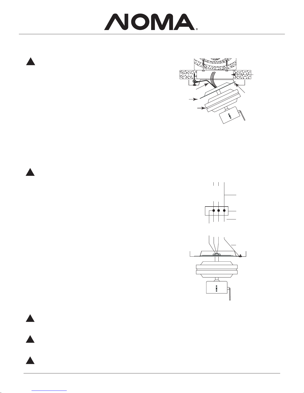
2. Carefully lift the fan motor assembly (without the blades) and
insert the plate of the fan motor assembly into the slot in
the mounting bracket as shown in Fig. 4.
3. Screw the hook screw to the building structure. Hook the safety cable
to the hook screw as shown in Fig. 4.
1. Unscrew three mounting bracket screws from the mounting bracket
and plate.
You are now ready to make the electrical connections.
Hanging the Fan
Fig. 4
Warning: Turn off the power.
Follow the steps below to hang your fan properly.
!
5
Motor
Slot
Outlet box
Safety cable
Plate
If you feel you do not have enough electrical wiring knowledge
or experience, have your fan installed by a licensed electrician.
Follow the steps below to connect the fan to your household
wiring. Use the wire nuts supplied with your fan. Secure the wire
nuts with electrical tape. Make sure there are no loose strands or
connections.
1. Connect the ground conductor of the 120 V supply (this may
be a bare wire or a wire with green-coloured insulation) to the
green ground lead(s) of the fan (see Fig. 5).
2. Connect the fan motor white wire to the supply white (neutral)
wire using a wire nut (see Fig. 5).
3. Connect the fan motor black wire to the supply black (hot)
wire using a wire nut (see Fig. 5).
4. Connect the blue wire for the light kit to the black (hot) household
supply wire using a wire nut (see Fig. 5).
5. Turn wire nut connections upward, spreading them apart so
the green (ground) will be on one side of the outlet box and the
white, black and blue wires will be on the other side, and push
carefully up into the outlet box.
Making the Electrical Connections
Fig. 5
Warning: To avoid possible electric shock, be sure
electricity is turned off at the main fuse box before
wiring.
!
Warning: To reduce the risk of electric shock or fire, do not
use this fan with any solid-state fan-speed control device. It
will permanently damage the electronic circuitry.
!
!
Warning: Check to see that all connections are tight, including ground, and that no bare wire is visible at the wire nuts,
except for the ground wire.
!
Warning: Electrical diagrams are for reference only.
Optional use of any light kit must be UL listed and marked
"suitable for use with this fan."
SUPPLY CIRCUIT
BLACK
WHITE
BLACK
WHITE
BLUE
GREEN
Outlet box
Ground
conductor
Green
ground
lead
Ground from plate
6
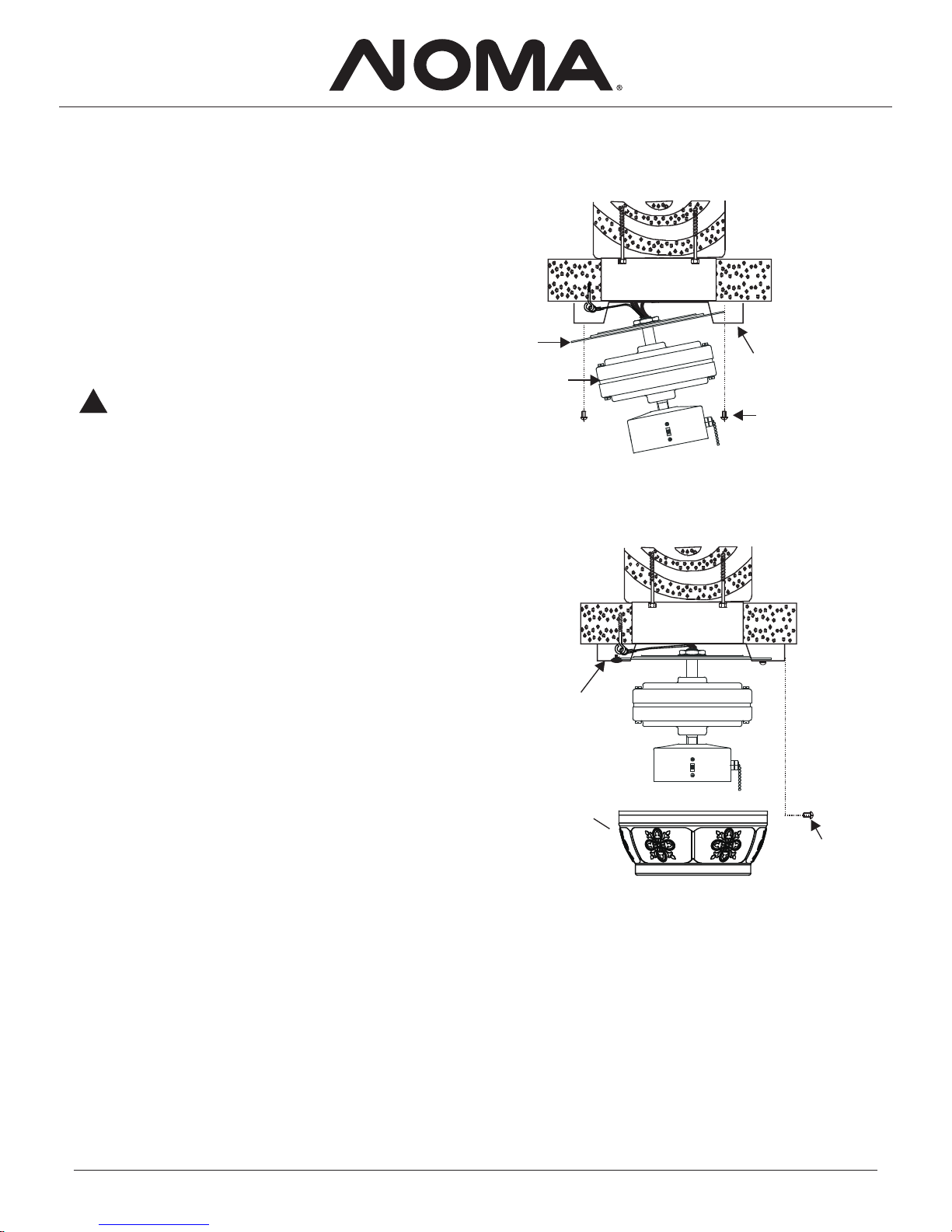
1. Tilt the motor assembly up into position under the mounting
2. Unscrew the 4 motor housing screws from the side of the
mounting bracket.
plate. Secure the plate to the mounting bracket with the 3
mounting bracket screws provided (see Fig. 7).
3. Carefully lift the motor housing onto the mounting bracket,
properly align the holes and secure the motor housing with the
4 motor housing screws supplied (see Fig. 8).
Finishing the Fan Installation
Fig. 7
Fig. 8
Warning: Do not leave fan assembly unattended until
all four mounting bracket screws are engaged and
firmly tightened.
!
Mounting
bracket
Screws
Motor
housing
Screws
Mounting
plate
Motor
Mounting
bracket
 Loading...