

Page 1

Chapter 6: Installing the Unit and Installation Check Off List
T able of Contents
Unit Installation Overview 6-1. . . . . . . . . . . . . . . . . . . . . . . . . . . . . . . . . . . . . . . . .
Overview 6-1. . . . . . . . . . . . . . . . . . . . . . . . . . . . . . . . . . . . . . . . . . . . . . . .
Unit Installation Procedure Order 6-1. . . . . . . . . . . . . . . . . . . . . . . . . . . . .
Connector Locations 6-2. . . . . . . . . . . . . . . . . . . . . . . . . . . . . . . . . . . . . . . . . . . . . .
Connector Locations 6-2. . . . . . . . . . . . . . . . . . . . . . . . . . . . . . . . . . . . . . .
Attaching Back Fin Cover to Unit 6-5. . . . . . . . . . . . . . . . . . . . . . . . . . . . . . . . . . .
Objective 6-5. . . . . . . . . . . . . . . . . . . . . . . . . . . . . . . . . . . . . . . . . . . . . . . .
When to Use the Fin Covers 6-5. . . . . . . . . . . . . . . . . . . . . . . . . . . . . . . . .
Procedure 6-5. . . . . . . . . . . . . . . . . . . . . . . . . . . . . . . . . . . . . . . . . . . . . . . .
Attaching Optional Installation Handles to the Unit 6-6. . . . . . . . . . . . . . . . . . . . .
Objective 6-6. . . . . . . . . . . . . . . . . . . . . . . . . . . . . . . . . . . . . . . . . . . . . . . .
Required Tools and Materials 6-6. . . . . . . . . . . . . . . . . . . . . . . . . . . . . . . .
Procedure to Attach the Installation Handles to the Unit 6-6. . . . . . . . . . .
Attaching Unit to Mounting Bracket 6-8. . . . . . . . . . . . . . . . . . . . . . . . . . . . . . . . .
Objective 6-8. . . . . . . . . . . . . . . . . . . . . . . . . . . . . . . . . . . . . . . . . . . . . . . .
Background 6-8. . . . . . . . . . . . . . . . . . . . . . . . . . . . . . . . . . . . . . . . . . . . . .
Tools and Materials 6-8. . . . . . . . . . . . . . . . . . . . . . . . . . . . . . . . . . . . . . . .
Procedure to Attach the Unit to the Mounting Bracket 6-9. . . . . . . . . . . . .
Earth Ground Cabling 6-11. . . . . . . . . . . . . . . . . . . . . . . . . . . . . . . . . . . . . . . . . . . . .
Objective 6-11. . . . . . . . . . . . . . . . . . . . . . . . . . . . . . . . . . . . . . . . . . . . . . . .
Other Grounding Considerations 6-11. . . . . . . . . . . . . . . . . . . . . . . . . . . . . .
Cable Description 6-11. . . . . . . . . . . . . . . . . . . . . . . . . . . . . . . . . . . . . . . . .
Tools and Materials 6-11. . . . . . . . . . . . . . . . . . . . . . . . . . . . . . . . . . . . . . . .
Attaching Front Fin Cover to Unit 6-14. . . . . . . . . . . . . . . . . . . . . . . . . . . . . . . . . . .
Objective 6-14. . . . . . . . . . . . . . . . . . . . . . . . . . . . . . . . . . . . . . . . . . . . . . . .
When to Use the Fin Covers 6-14. . . . . . . . . . . . . . . . . . . . . . . . . . . . . . . . .
Procedure 6-14. . . . . . . . . . . . . . . . . . . . . . . . . . . . . . . . . . . . . . . . . . . . . . . .
Attaching the Site I/O Junction Box to the Unit 6-15. . . . . . . . . . . . . . . . . . . . . . . .
Objective 6-15. . . . . . . . . . . . . . . . . . . . . . . . . . . . . . . . . . . . . . . . . . . . . . . .
Required Tools and Materials 6-15. . . . . . . . . . . . . . . . . . . . . . . . . . . . . . . .
Procedure to Attach the Site I/O Junction Box to the Unit 6-15. . . . . . . . . .
Procedure to Attach a Site I/O Cap to the Unit (optional) 6-16. . . . . . . . . .
6
DEC 2000
SCt300 BTS Hardware Installation, ATP and FRU Procedures
PRELIMINARY
Page 2

Table of Contents – continued
Attaching the Short Duration Battery to the Unit (optional) 6-17. . . . . . . . . . . . . . .
Objective 6-17. . . . . . . . . . . . . . . . . . . . . . . . . . . . . . . . . . . . . . . . . . . . . . . .
Required Tools and Materials 6-17. . . . . . . . . . . . . . . . . . . . . . . . . . . . . . . .
Procedure to Attach the Battery to the Unit 6-17. . . . . . . . . . . . . . . . . . . . .
Short Duration Battery Cabling 6-19. . . . . . . . . . . . . . . . . . . . . . . . . . . . . . . . . . . . .
Objective 6-19. . . . . . . . . . . . . . . . . . . . . . . . . . . . . . . . . . . . . . . . . . . . . . . .
Battery Cable 6-19. . . . . . . . . . . . . . . . . . . . . . . . . . . . . . . . . . . . . . . . . . . . .
Procedure 6-19. . . . . . . . . . . . . . . . . . . . . . . . . . . . . . . . . . . . . . . . . . . . . . . .
AC Power Cabling 6-21. . . . . . . . . . . . . . . . . . . . . . . . . . . . . . . . . . . . . . . . . . . . . . .
Objective 6-21. . . . . . . . . . . . . . . . . . . . . . . . . . . . . . . . . . . . . . . . . . . . . . . .
Cable Description 6-21. . . . . . . . . . . . . . . . . . . . . . . . . . . . . . . . . . . . . . . . .
Power Cable and Connector Signal Information 6-21. . . . . . . . . . . . . . . . . .
Procedure 6-21. . . . . . . . . . . . . . . . . . . . . . . . . . . . . . . . . . . . . . . . . . . . . . . .
DC Power Cabling 6-23. . . . . . . . . . . . . . . . . . . . . . . . . . . . . . . . . . . . . . . . . . . . . . .
Objective 6-23. . . . . . . . . . . . . . . . . . . . . . . . . . . . . . . . . . . . . . . . . . . . . . . .
Cable Decription 6-23. . . . . . . . . . . . . . . . . . . . . . . . . . . . . . . . . . . . . . . . . .
Power Cable and Connector Signal Information 6-23. . . . . . . . . . . . . . . . . .
Procedure 6-23. . . . . . . . . . . . . . . . . . . . . . . . . . . . . . . . . . . . . . . . . . . . . . . .
Antenna Cabling for Sites Equipped With
Customer–Supplied Site I/O Interface 6-25. . . . . . . . . . . . . . . . . . . . . . . . . . . . . . . .
Objective 6-25. . . . . . . . . . . . . . . . . . . . . . . . . . . . . . . . . . . . . . . . . . . . . . . .
Cable Labels 6-25. . . . . . . . . . . . . . . . . . . . . . . . . . . . . . . . . . . . . . . . . . . . .
Cable Descriptions 6-25. . . . . . . . . . . . . . . . . . . . . . . . . . . . . . . . . . . . . . . . .
6
Antenna Cabling for Sites Equipped with Optional Primary Surge Suppressor 6-30
MIB Cabling for Multi–Unit Configurations 6-38. . . . . . . . . . . . . . . . . . . . . . . . . . .
SU Cabling 6-44. . . . . . . . . . . . . . . . . . . . . . . . . . . . . . . . . . . . . . . . . . . . . . . . . . . . .
Procedure 6-25. . . . . . . . . . . . . . . . . . . . . . . . . . . . . . . . . . . . . . . . . . . . . . . .
Objective 6-30. . . . . . . . . . . . . . . . . . . . . . . . . . . . . . . . . . . . . . . . . . . . . . . .
Cable Labels 6-30. . . . . . . . . . . . . . . . . . . . . . . . . . . . . . . . . . . . . . . . . . . . .
Cable Descriptions 6-30. . . . . . . . . . . . . . . . . . . . . . . . . . . . . . . . . . . . . . . . .
Procedure 6-30. . . . . . . . . . . . . . . . . . . . . . . . . . . . . . . . . . . . . . . . . . . . . . . .
Overview 6-38. . . . . . . . . . . . . . . . . . . . . . . . . . . . . . . . . . . . . . . . . . . . . . . .
Cable Labels 6-38. . . . . . . . . . . . . . . . . . . . . . . . . . . . . . . . . . . . . . . . . . . . .
Tools and Equipment 6-38. . . . . . . . . . . . . . . . . . . . . . . . . . . . . . . . . . . . . . .
Procedure 6-41. . . . . . . . . . . . . . . . . . . . . . . . . . . . . . . . . . . . . . . . . . . . . . . .
Objective 6-44. . . . . . . . . . . . . . . . . . . . . . . . . . . . . . . . . . . . . . . . . . . . . . . .
Cable Labels 6-44. . . . . . . . . . . . . . . . . . . . . . . . . . . . . . . . . . . . . . . . . . . . .
Tools and Equipment 6-44. . . . . . . . . . . . . . . . . . . . . . . . . . . . . . . . . . . . . . .
Procedure to Install SU Cabling for Single Unit 6-47. . . . . . . . . . . . . . . . . .
SU Cabling for Multi–Unit Configurations 6-48. . . . . . . . . . . . . . . . . . . . . .
Terminating Unused Connections 6-51. . . . . . . . . . . . . . . . . . . . . . . . . . . . . . . . . . . .
Objective 6-51. . . . . . . . . . . . . . . . . . . . . . . . . . . . . . . . . . . . . . . . . . . . . . . .
Termination List (MicroCell) 6-51. . . . . . . . . . . . . . . . . . . . . . . . . . . . . . . .
Termination List (PicoCell) 6-51. . . . . . . . . . . . . . . . . . . . . . . . . . . . . . . . . .
Procedure 6-51. . . . . . . . . . . . . . . . . . . . . . . . . . . . . . . . . . . . . . . . . . . . . . . .
SCt300 BTS Hardware Installation, ATP and FRU Procedures
PRELIMINARY
DEC 2000
Page 3

Table of Contents – continued
Powering on Unit and Mounting the Solar Cover 6-52. . . . . . . . . . . . . . . . . . . . . . .
Objective 6-52. . . . . . . . . . . . . . . . . . . . . . . . . . . . . . . . . . . . . . . . . . . . . . . .
You May Want to Wait 6-52. . . . . . . . . . . . . . . . . . . . . . . . . . . . . . . . . . . . . .
Tools Required 6-52. . . . . . . . . . . . . . . . . . . . . . . . . . . . . . . . . . . . . . . . . . . .
Procedure to Power On Unit and Mount Solar Cover 6-52. . . . . . . . . . . . . .
Procedure to Power On Surge Suppressor, Unit and Mount Solar Cover 6-52
Site Cleanup 6-56. . . . . . . . . . . . . . . . . . . . . . . . . . . . . . . . . . . . . . . . . . . . . . . . . . . .
Remove protective covering 6-56. . . . . . . . . . . . . . . . . . . . . . . . . . . . . . . . .
Lighting fixtures 6-56. . . . . . . . . . . . . . . . . . . . . . . . . . . . . . . . . . . . . . . . . .
Tools 6-56. . . . . . . . . . . . . . . . . . . . . . . . . . . . . . . . . . . . . . . . . . . . . . . . . . .
Materials 6-56. . . . . . . . . . . . . . . . . . . . . . . . . . . . . . . . . . . . . . . . . . . . . . . .
Remove debris 6-56. . . . . . . . . . . . . . . . . . . . . . . . . . . . . . . . . . . . . . . . . . . .
Environment 6-56. . . . . . . . . . . . . . . . . . . . . . . . . . . . . . . . . . . . . . . . . . . . .
Installation Completion Checklist 6-57. . . . . . . . . . . . . . . . . . . . . . . . . . . . . . . . . . .
Directions 6-57. . . . . . . . . . . . . . . . . . . . . . . . . . . . . . . . . . . . . . . . . . . . . . . .
Installation completion checklist 6-58. . . . . . . . . . . . . . . . . . . . . . . . . . . . . .
6
DEC 2000
SCt300 BTS Hardware Installation, ATP and FRU Procedures
PRELIMINARY
Page 4

Table of Contents – continued
Notes
6
SCt300 BTS Hardware Installation, ATP and FRU Procedures
PRELIMINARY
DEC 2000
Page 5

Unit Installation Overview
Overview
Unit Installation Procedure
Order
This chapter provides the procedures for unit installation and cabling.
The site cabling has been installed and routed to the location of the BTS.
In this chapter, the cables will be attached to the unit(s). Cabling
installation will be repeated as necessary for each unit at the BTS.
This chapter provides the information and procedures to:
S Attach the unit to the mounting bracket
S Attach cables to the unit
S Power on the unit
S Mount the solar covers
S Complete the installation completion checklist
The process of installing the unit requires that the following procedures
be completed in the order shown:
1. Attaching fin covers to the unit – optional
2. Attaching the installation handles to the unit
3. Attaching the unit to the mounting bracket and removing the
installation handles
4. Attaching earth ground cable and optional master ground cable.
5. Attaching the Site I/O junction box to the unit
6. Attaching the short duration battery (optional)
7. Attaching the AC input power or DC input power cable
8. Attaching antenna cable(s)
9. Attaching the MIB cables (optional)
10. Attaching the SU cables (optional)
11. Terminating unused connectors
12. Powering on the unit
13. Mounting solar cover
14. Cleaning up site
15. Filling out the installation completion checklist
6
DEC 2000
SCt300 BTS Hardware Installation, ATP and FRU Procedures
PRELIMINARY
6-1
Page 6

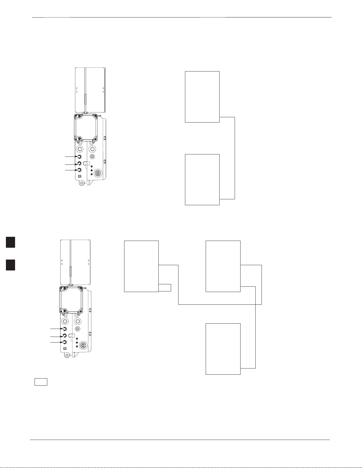
Connector Locations
Connector Locations
Figure 6-1, Figure 6-2, and Figure 6-3 show the location of the cable
connectors on the Microcell, Picocell, and Primary Surge Suppressor.
The system configuration determines which connectors are used.
Figure 6-1: Location of MicroCell Unit Connectors
SITE I/O
JUNCTION BOX
6
DC POWER BREAKER
DC INPUT
MIB C
MIB B
MIB A
ANTENNA A
TIE WRAP LOCATION
AC POWER BREAKER
AC INPUT
SU RF
SU 2
SU 1
ANTENNA B
0169–O_IL.doc
6-2
SCt300 BTS Hardware Installation, ATP and FRU Procedures
PRELIMINARY
DEC 2000
Page 7

Connector Locations – continued
Figure 6-2: Location of PicoCell Unit Connectors
SITE I/O
JUNCTION BOX
DC POWER BREAKER
DC INPUT
MIB C
AC POWER BREAKER
AC INPUT
MIB B
MIB A
ANTENNA A
TIE WRAP LOCATION
SU RF
SU 2
SU 1
6
0170–O_IL.doc
DEC 2000
SCt300 BTS Hardware Installation, ATP and FRU Procedures
PRELIMINARY
6-3
Page 8

Connector Locations – continued
Figure 6-3: Location of Primary Surge Suppressor Connectors
LEFT SIDE
SITE I/O 2
SITE I/O INPUT
(Conduit Hole)
GROUND 4
GROUND 3
GROUND 2
AC POWER 2
AC POWER 3
AC POWER 4
ANTENNA PROTECTOR 1
ANTENNA PROTECTOR 6
(FOR FUTURE EXPANSION)
ANTENNA PROTECTOR 5
(FOR FUTURE EXPANSION)
6
ANTENNA PROTECTOR 4
(FOR FUTURE EXPANSION)
ANTENNA PROTECTOR 2
ANTENNA PROTECTOR 3
(FOR FUTURE EXPANSION)
RIGHT SIDE
SITE I/O 1
GROUND 1
EARTH
GROUND
AC POWER 1
AC INPUT
(Conduit Hole)
6-4
SCt300 BTS Hardware Installation, ATP and FRU Procedures
PRELIMINARY
DEC 2000
Page 9

Attaching Back Fin Cover to Unit
Objective
The objective of this procedure is to attach the back fin cover to the
PicoCell and MicroCell units. The front fin cover is mounted to the unit
after the unit is mounted to the mounting bracket.
When to Use the Fin Covers
The fin covers should always be used in an indoor application.
Procedure
Attach the rear fin cover to the unit by following the procedures in
Table 6-1 and the information in Figure 6-4.
Step Action
1 Install back fin cover prior to placing unit on the mounting
Table 6-1: Procedure to Attach Rear Fin Cover to Units
bracket.
2 Center fin cover on the fins of the unit. See Figure 6-4 for
snap locations.
3 Align snap with center tab on fins.
4 Push fin cover into place.
Figure 6-4: Attaching Back Fin Cover to Unit (Picocell Shown)
LOCATION OF SNAPS T O ATTACH
FIN COVER TO UNIT
6
PICOCELL FINS
DEC 2000
SCt300 BTS Hardware Installation, ATP and FRU Procedures
PRELIMINARY
6-5
Page 10

Attaching Optional Installation Handles to the Unit
Objective
The objective of this procedure is to attach the optional installation
handles to the unit. The location for the handles is shown in Figure 6-5.
The handles should be used when lifting or carrying the unit.
Required Tools and Materials
T ools
Attaching the installation handles to the unit requires:
S T30 Torx tamper bit
S Torque driver wrench, 1/4–in. hex female drive, 0–10 N–M
Motorola parts
Table 6-2 lists the parts necessary to do this procedure.
Table 6-2: Installation Handle Kit – SGLN5754
Quantity Part Number Description
4 387541C03 Screws M6x190
1 0787668C01 Left Handle
1 0787668C02 Right Handle
6
Procedure to Attach the
Installation Handles to the Unit
Use the procedure in Table 6-3 to attach the installation handles to the
unit. Refer to Figure 6-5.
Table 6-3: Procedure to Attach the Installation Handles to the Unit
Step Action
1 Hold the left handle in position and start the upper screw. The
handles are marked left and right. Refer to Figure 6-5.
2 Position and start the lower screw.
3 Use a T30 Torx tamper bit to torque both screws to 5.0 N–m.
4 Repeat steps 1–3 for the right handle.
6-6
SCt300 BTS Hardware Installation, ATP and FRU Procedures
PRELIMINARY
DEC 2000
Page 11

Attaching Installation Handles to the Unit – continued
Figure 6-5: Attaching the Installation Handles to the Unit (Picocell Shown)
HOLES USED FOR
MOUNTING HANDLES
HOLES USED FOR
MOUNTING HANDLES
LEFT HANDLE
6
RIGHT HANDLE
M6X19 (4)
DEC 2000
SCt300 BTS Hardware Installation, ATP and FRU Procedures
PRELIMINARY
0164–O_IL.doc
6-7
Page 12

Attaching Unit to Mounting Bracket
Objective
The objective of this procedure is to attach the unit to the mounting
bracket. This procedure applies to mounting brackets that are attached to
a rack, wall, ceiling or pole. This procedure also applies to both the
MicroCell and PicoCell units.
Background
The unit attaches to the mounting bracket with two (2) M6 screws and
the provided pin or a customer–supplied padlock.
WARNING
For ceiling mount applications, two people must do this
procedure. One person must steady the unit while the
second person installs the unit.
NOTE
The handles should be mounted to the unit before
mounting the unit to the bracket. The handles should be
used to lift the unit onto the bracket. If the solar cover is to
be used, the back cover must be attached prior to mounting
the unit. Remove the handles once the unit has been
6
T ools and Materials
The following tools and materials are required to attach the unit to the
mounting bracket:
secured to the mounting bracket.
S Torque driver wrench, 1/4–in. hex female drive, 0–10 N–M
S T30 Torx tamper bit
S Two M6X19 screws (Motorola Part Number 0387541C03)
6-8
SCt300 BTS Hardware Installation, ATP and FRU Procedures
PRELIMINARY
DEC 2000
Page 13

Attaching Unit to Mounting Bracket – continued
Procedure to Attach the Unit to
the Mounting Bracket
Follow the procedure in Table 6-4 to attach the unit to the mounting
bracket. Refer to Figure 6-6.
WARNING
For ceiling mount applications, two people must do this
procedure. One person must steady the unit while the
second person installs the unit.
CAUTION
Use caution when resting the MicroCell or PicoCell unit
on the hooks of the mounting bracket. Do not leave unit
supported by hooks only.
Table 6-4: Procedure to Attach the Unit to the Mounting Bracket
Step Action
1 Lift the unit using the installation handles and place it on the
mounting bracket by aligning the bracket’s upper arms into
the rectangular cutouts in the heatsink. The unit will need to
be raised up slightly so that the lower bracket flange does not
contact the unit’s lower surface. For a ceiling application, use
caution when resting the PicoCell on the hooks on the
mounting bracket.
2 Use a T30 Torx tamper bit to start, but not tighten, both
screws in the location shown in Figure 6-6.
3 At the bottom of the unit, align the hole in the mounting
bracket with the hole in the unit. Place the pin or
customer–supplied padlock through this hole. Screw pin
together and tighten firmly.
4 Use a T30 Torx tamper bit to torque the two mounting screws
to 5.0 N–M.
5 Use a T30 Torx tamper bit to remove the installation handles.
6
DEC 2000
SCt300 BTS Hardware Installation, ATP and FRU Procedures
PRELIMINARY
6-9
Page 14

Attaching Unit to Mounting Bracket – continued
Figure 6-6: Attaching the Unit to the Mounting Bracket
HOOKS
M6 SCREWS (2)
SLIDE PIN THROUGH HOLES IN
BRACKET AND SCREW TOGETHER
6
ATTACH THE HANDLES TO THE UNIT
BEFORE LIFTING
MOUNTING BRACKET
6-10
MOUNTING BRACKET
PIN (P/N 5587660C03)
SCt300 BTS Hardware Installation, ATP and FRU Procedures
PRELIMINARY
DEC 2000
Page 15

Earth Ground Cabling
Objective
Other Grounding
Considerations
Cable Description
The objective of this procedure is to attach the earth ground cabling to
one or more MicroCell or PicoCell units. This procedure covers just the
grounding cables that attach to the MicroCell or PicoCell.
Grounding considerations beyond the ground cables that attach to the
MicroCell and PicoCell are summarized in Appendix A. Refer to
Appendix A and the site documentation for other grounding
considerations.
If your site is equipped with the optional Primary Surge Suppressor,
refer to the “Power, Earth Ground, and Battery Cabling” Procedure in
chapter 4 for information about installing the Master Ground cable.
The following cables in Table 6-5 are necessary to do this procedure.
Table 6-5: Ground Cable Description and Part Number
Cable Qty. Part Number Description
A 1–4 3087701C02 Ground cable, 8 -AWG, insulated copper wire. Requires one ring lug
connector. Used for Primary Surge Suppressor Installation.
B 1–4 3087701C01 Ground cable, Site I/O Junction Box to Bracket.
Y 1 Customer
Supplied
T ools and Materials
Master Ground Cable, 6 -AWG, insulated copper wire. Used for both
Primary Surge Suppressor and non–Primary Surge Suppressor
installations.
The following tools are required to attach ground cabling to the
MicroCell and PicoCell units.
S 13 mm torque wrench set to 5.0 N–M
S Flathead screwdriver bit
S T30 TORX bit
Procedure
Use the following procedure to attach the ground cables. Refer to
Table 6-6 and Figure 6-7.
Table 6-6: Procedure to Attach the Earth Ground Cables
6
DEC 2000
Step Action
1 Remove the hex nuts and lock washers from the ground stud
on the mounting bracket.
2 Attach ground cable (cable A or Y) to ground stud on
mounting bracket.
. . . continued on next page
SCt300 BTS Hardware Installation, ATP and FRU Procedures
PRELIMINARY
6-11
Page 16

Earth Ground Cabling – continued
Step Action
3 Replace one lock washer and nut on the ground stud and
4 Attach the ground cable from the Site I/O junction box (cable
5 Replace the second lockwasher and hex nut to the ground stud
Figure 6-7: Detail Location of Ground Stud
Table 6-6: Procedure to Attach the Earth Ground Cables
tighten to 5 N–m.
B) to the ground stud on the mounting bracket.
on mounting bracket. Use a torque wrench and a 13mm
socket to tighten to 5.0 N–m.
GROUNDING STUD
CABLE A OR Y
B
TO CUSTOMER DEFINED MASTER
6
GROUND PLATE OR CARRIER
GROUND CONNECTOR ON PRIMARY
SURGE SUPPRESSOR
6-12
SCt300 BTS Hardware Installation, ATP and FRU Procedures
PRELIMINARY
DEC 2000
Page 17

Earth Ground Cabling – continued
Figure 6-8: Grounding Stud on Mounting Bracket
LOCK WASHER
MOUNTING BRACKET
NUT
LOCK WASHER
NUT
GROUNDING STUD
CUSTOMER UNIT
GROUND LUG
SITE I/O
GROUND LUG
6
DEC 2000
SCt300 BTS Hardware Installation, ATP and FRU Procedures
PRELIMINARY
6-13
Page 18

Attaching Front Fin Cover to Unit
Objective
The objective of this procedure is to attach the front fin cover to the
PicoCell and MicroCell units.
When to Use the Fin Covers
Always use fin covers for an indoor application.
Procedure
Follow the procedure in Table 6-7 to attach the front fin cover to the
unit. Refer to Figure 6-9.
Step Action
1 Center fin cover on the fins of the unit. See Figure 6-9 for
Table 6-7: Procedure to Attach Front Fin Cover to Unit
snap locations.
2 Align snap with center tab on fins.
3 Push fin cover into place.
Figure 6-9: Attaching Front Fin Cover to Unit (Picocell Shown)
6
LOCATION OF SNAPS T O ATTACH
FIN COVER TO UNIT
PICOCELL FINS
6-14
SCt300 BTS Hardware Installation, ATP and FRU Procedures
PRELIMINARY
DEC 2000
Page 19

Attaching the Site I/O Junction Box to the Unit
Objective
The objective of this procedure is to attach the Site I/O junction box to
the unit. The location for the Site I/O junction box is shown in
Figure 6-10.
If you do not mount a Site I/O Junction box to a unit, leave the installed
Site I/O caps on the Site I/O Junction box connectors.
Required Tools and Materials
The following tools and materials are necessary to do this procedure:
S Torque driver wrench, 1/4–in. hex female drive, 0–10 N–M
S T30 Torx tamper bit
S Site I/O Junction box
Procedure to Attach the Site
I/O Junction Box to the Unit
Follow the procedure below to attach the site I/O junction box to the
unit.
Table 6-8: Procedure to Attach the Site I/O Junction Box to the Unit
Step Action
1 Use a T30 TORX bit to remove Site I/O Cap from the Site
I/O connector .
NOTE
Save Site I/O Cap for future use.
2 Remove the Site I/O Plate from the Site I/O Junction Box.
3 Attach one end of the Site I/O Ground cable to the Site I/O
Junction Box. Use one M6x19 tamper–resistant screw.
Torque to 5.0 N–m.
4 The free end of the Site I/O junction box cable should be
connected to the customer–supplied Site I/O interface or to
the Primary Surge Suppressor.
5 Position the Site I/O junction box as shown in NO TAG.
6 Insert the Site I/O junction box on to the housing, using the
alignment feature on the housing.
6
DEC 2000
7 Use a T30 Torx tamper bit to tighten (but do not torque) the
upper tamper resistant screw.
8 Tighten but do not torque the lower tamper resistant screw.
9 Use a T30 Torx tamper bit to torque the upper and lower
screw to 5 N–m.
SCt300 BTS Hardware Installation, ATP and FRU Procedures
PRELIMINARY
6-15
Page 20

Attaching the Site I/O Junction Box to the Unit – continued
Figure 6-10: Attaching the Site I/O Junction Box to the Unit
SITE I/O JUNCTION BOX
CAPTIVE SCREWS
6
Procedure to Attach a Site I/O
Cap to the Unit (optional)
Use the following procedure in Table 6-9 to attach a Site I/O Cap to the
unit.
Table 6-9: Procedure to Attach a Site I/O Cap to the Unit (optional)
Step Action
1 Position the Site I/O cap, Motorola Part Number
3888121C01, over the Site I/O socket.
2 Use a T30 Torx tamper bit to tighten (but do not torque) the
upper tamper resistant screw.
3 Tighten but do not torque the lower tamper resistant screw.
4 Use a T30 Torx tamper bit to torque the upper and lower
screw to 5 N–m.
6-16
SCt300 BTS Hardware Installation, ATP and FRU Procedures
PRELIMINARY
DEC 2000
Page 21

Attaching the Short Duration Battery to the Unit (optional)
Objective
The objective of this procedure is to attach the short duration battery to
the unit.
Required Tools and Materials
Attaching the battery to the unit requires:
S T30 Torx tamper bit, 1/4–in. hex
S Torque driver wrench, 1/4–in. hex female drive, 0–10 N–M
S Two (2) Screws M6x19 (Motorola Part Number 0387541C03)
Procedure to Attach the
Battery to the Unit
Follow the procedure in Table 6-10 to attach the short duration battery to
the unit. Refer to Figure 6-11.
Table 6-10: Procedure to Attach the Short Duration Battery to the Unit
Step Action
1 Hold the battery in the position shown in Figure 6-11.
2 The two holes at the end of the battery should align with the
mounting holes on the unit. See Figure 6-11.
3 Start but do not tighten the M6x19 screws.
4 Using a T30 Torx tamper bit wrench, 1/4–in. hex female
drive, 0–10 N–M, torque the screws to 5 N–M.
6
DEC 2000
SCt300 BTS Hardware Installation, ATP and FRU Procedures
PRELIMINARY
6-17
Page 22

Attaching the Short Duration Battery to the Unit (optional) – continued
Figure 6-11: Attaching the Short Duration Battery to the Unit
M6X19 SCREWS (2)
CONNECT TO DC INPUT CONNECTOR
WHEN BATTERY HAS BEEN SECURED
6
SHORT DURA TION
BATTERY
6-18
SCt300 BTS Hardware Installation, ATP and FRU Procedures
PRELIMINARY
DEC 2000
Page 23

Short Duration Battery Cabling
Objective
The objective of this procedure is to attach the short duration battery
cable.
Battery Cable
The battery cable is part of the battery assembly. The same type
connector is used for the short duration battery and DC input cables.
Procedure
Use the following procedure in Table 6-11 to attach the short duration
battery (DC input) cable to the DC input connector. Refer to
Figure 6-12. The cable should be connected before the solar cover is
attached.
The short duration battery should not be opened under any
circumstances. No wire termination is required by the user except
connection to the BTS, with the provided connector.
Table 6-11: Procedure to Connect the Short Duration Battery Cable to
Unit
Step Action
1 Ensure that the ground wire has a connection to unit and the
Master Ground Bus (also called Master Ground Plate).
2 Verify that the DC power breaker is open. The white collar on
the breaker is visible when it is open.
3 Place the round, black connector of the DC input cable onto
the DC input connector on the BTS. Refer to Figure 6-12.
Turn the cable connector to align its key.
4 Hand tighten the connector (a clicking sound is heard, this is
normal). When the red line on the connector on the unit is
covered, connection is complete.
6
DEC 2000
SCt300 BTS Hardware Installation, ATP and FRU Procedures
PRELIMINARY
6-19
Page 24

Short Duration Battery Cabling – continued
Figure 6-12: Battery Cable Installation
DC INPUT CONNECTOR
BATTERY CABLE IS PART
OF BATTERY ASSEMBLY
6
6-20
SCt300 BTS Hardware Installation, ATP and FRU Procedures
PRELIMINARY
DEC 2000
Page 25

AC Power Cabling
Objective
Cable Description
The objective of this procedure is to attach the AC input power cable to
the unit. Use this procedure only when AC power is used to power the
unit.
If the Primary Surge Suppressor is not used, the AC Installation Box is
required for all outdoor mounting applications.
WARNING
This equipment uses dangerous voltages and is capable of
causing death. Use extreme caution when handling and
testing this equipment.
The following cables in Table 6-5 are necesary to do this procedure:
Table 6-12: AC Input Cable Description and Part Number
Cable Qty. Part Number Description
S 1–4 3087854C02 AC input cable, 18 AWG, 5 m, is designed for 120–240 VAC power
input. Cable has Deutsch connector on both ends.
Power Cable and Connector
Signal Information
The AC input connector is located on the side of the unit as shown in
Figure 6-13. The unit is designed for 88–260 VAC power input.
Procedure
Use the following procedure in Table 6-13 to connect the AC input cable
to the unit. The AC input cable should be connected before the solar
cover is attached.
Table 6-13: Procedure to Connect AC Power to the Unit
Step Action
1 Ensure that the ground wire has a connection to the Master
Ground Bus (also called Master Ground Plate).
2 Verify that the AC power breaker is open. The white collar on
the breaker is visible when it is open.
6
DEC 2000
3 Place the round, black connector on the AC input cable (cable
S) onto the AC input connector. See Figure 6-13. Turn the
cable connector to align its key.
4 Hand tighten the connector (a clicking sound is heard, this is
normal). When the red line on the connector on the unit is
covered, connection is complete.
SCt300 BTS Hardware Installation, ATP and FRU Procedures
PRELIMINARY
6-21
Page 26

AC Power Cabling – continued
Figure 6-13: AC Power Cabling Details
AC POWER
BREAKER
AC INPUT
CONNECTOR
AC INSTALL BOX
S
OR AC POWER
SOURCE OR
OPTIONAL
PRIMARY SURGE
SUPPRESSOR
AC CONDUIT
6
6-22
SCt300 BTS Hardware Installation, ATP and FRU Procedures
PRELIMINARY
DEC 2000
Page 27

DC Power Cabling
Objective
Cable Decription
The objective of this procedure is to attach the DC input cable to the
unit. Use this procedure only when DC power is used to power the unit.
WARNING
This equipment uses dangerous voltages and is capable of
causing death. Use extreme caution when handling and
testing this equipment.
The following cables in Table 6-14 are necessary to do this procedure.
Table 6-14: DC Input Cable Description and Part Number
Cable Qty. Part Number Description
U 1 3087854C04 DC input cable, 18 AWG, 5 m, is designed for 20 to 30 VDC power
input.
Power Cable and Connector
Signal Information
The DC input connector is located on the side of the unit. The unit is
designed for 40 to 60 VDC.
Procedure
Use the following procedure in Table 6-15 to connect the DC input cable
to the unit. Refer to Figure 6-14. The DC input cable should be
connected before the solar cover is attached.
Table 6-15: Procedure to Connect DC Power to the Unit
Step Action
1 Ensure that the ground wire has a connection to the Master
Ground Bus (also called Master Ground Plate).
2 Verify that the DC power breaker is open. The white collar on
the breaker is visible when it is open.
6
DEC 2000
3 Place the round, black connector of the DC input cable onto
the DC input connector. See Figure 6-14. Turn the cable
connector to align its key.
4 Hand tighten the connector (a clicking sound is heard, this is
normal). When the red line on the connector on the unit is
covered, connection is complete.
SCt300 BTS Hardware Installation, ATP and FRU Procedures
PRELIMINARY
6-23
Page 28

DC Power Cabling – continued
Figure 6-14: DC Power Cabling Details
DC POWER BREAKER
DC INPUT
CONNECTOR
DC POWER
SOURCE
U
0178–O_IL.doc
6
6-24
SCt300 BTS Hardware Installation, ATP and FRU Procedures
PRELIMINARY
DEC 2000
Page 29

Antenna Cabling for Sites Equipped With Customer–Supplied Site I/O
Interface
Objective
The objective of this procedure is to attach the antenna cabling for one or
more units.
If your BTS is equipped with the optional Primary Surge Suppressor,
then proceed to the “Antenna Cabling for Sites Equipped with the
Optional Primary Surge Suppressor” procedure in Chapter 6.
Cable Labels
The cable designations are referenced to Table 6-16 in the “Cable
Description” area of Chapter 4.
Cable Descriptions
The following cables in Table 6-16 are necessary to do this procedure.
Table 6-16: Cable Descriptions and Part Numbers
Cable Qty. Part Number Description
C 1–8 Customer
Supplied
Procedure
Antenna cable, 50–Ohm coaxial terminated with at least one male,
N–type connector.
The cabling is installed between the unit(s) and the external lightning
arrestors. If lightning arrestors are not present, it connects to the
antenna.
If your BTS has one unit, cable the unit as shown in Figure 6-15.
Torque the connectors to 4.3 N–M.
If your BTS has more than one unit, cable the unit as shown in
Figure 6-18, Figure 6-17, Figure 6-16, Figure 6-21, Figure 6-20, or
Figure 6-19.
6
DEC 2000
SCt300 BTS Hardware Installation, ATP and FRU Procedures
PRELIMINARY
6-25
Page 30

Antenna Cabling for Sites Equipped With Customer–Supplied Site I/O
Interface
Figure 6-15: Antenna Cabling Details for MicroCell and PicoCell Unit
– continued
MICROCELL UNIT
PICOCELL UNIT
ANTENNA A
6
C
LIGHTNING
ARRESTOR
C
RX
ANTENNA
C
LIGHTNING
ARRESTOR
C
TX/RX
ANTENNA
ANTENNA B
ANTENNA A
C
LIGHTNING
ARRESTOR
C
TX/RX
ANTENNA
6-26
SCt300 BTS Hardware Installation, ATP and FRU Procedures
PRELIMINARY
DEC 2000
Page 31

Antenna Cabling for Sites Equipped With Customer–Supplied Site I/O
Interface
Figure 6-16: Antenna Cabling for Two Microcells
ANTENNA A
ANTENNA B
– continued
MICROCELL UNIT
KEY
= LIGHTNING ARRESTOR
LA
RFT
= 50 OHM RF TERMINAT OR
MICROCELL 1
ANT A
ANT B
MICROCELL 2
ANT A
ANT B
RFT
RFT
C
LA
C
LA
ANTENNA 1
TX/RX
ANTENNA 2
TX/RX
Figure 6-17: Antenna Cabling for Three Microcells
MICROCELL UNIT
ANT A
ANT B
ANTENNA A
ANTENNA B
KEY
= LIGHTNING ARRESTOR
LA
RFT
= 50 OHM RF TERMINAT OR
6
MICROCELL 1MICROCELL 3
ANT A
RFT
ANT B
C
MICROCELL 2
ANT A
RFT
ANT B
C
LA
C
LA
LA
C
LA
ANTENNA 1
TX/RX
ANTENNA 3
TX/RX
ANTENNA 2
TX/RX
ANTENNA 4
RX
DEC 2000
SCt300 BTS Hardware Installation, ATP and FRU Procedures
PRELIMINARY
6-27
Page 32

Antenna Cabling for Sites Equipped With Customer–Supplied Site I/O
Interface
Figure 6-18: Antenna Cabling for Four Microcells
– continued
MICROCELL UNIT
MICROCELL 1MICROCELL 3
ANTENNA A
ANTENNA B
RFT
KEY
= LIGHTNING ARRESTOR
LA
= 50 OHM RF TERMINAT OR
ANT A
ANT B
ANT A
ANT B
RFT
C
RFT
C
ANT A
RFT
ANT B
MICROCELL 2MICROCELL 4
ANT A
RFT
ANT B
LA
C
LA
LA
C
LA
ANTENNA 1
TX/RX
ANTENNA 3
TX/RX
ANTENNA 2
TX/RX
ANTENNA 4
TX/RX
6
Figure 6-19: Antenna Cabling for Two Picocells
PICOCELL UNIT
PICOCELL 1
ANTENNA A
6-28
KEY
= LIGHTNING ARRESTOR
LA
SCt300 BTS Hardware Installation, ATP and FRU Procedures
ANT A
PICOCELL 2
ANT A
C
LA
C
LA
ANTENNA 1
TX/RX
ANTENNA 2
TX/RX
DEC 2000
PRELIMINARY
Page 33

Antenna Cabling for Sites Equipped With Customer–Supplied Site I/O
Interface
Figure 6-20: Antenna Cabling for Three Picocells
– continued
ANTENNA A
LA
PICOCELL UNIT
KEY
= LIGHTNING ARRESTOR
ANT A
PICOCELL 1PICOCELL 3
ANT A
C
PICOCELL 2
ANT A
C
LA
LA
C
LA
ANTENNA 1
TX/RX
ANTENNA 3
TX/RX
ANTENNA 2
TX/RX
Figure 6-21: Antenna Cabling for Four Picocells
PICOCELL UNIT
ANT A
ANTENNA A
KEY
= LIGHTNING ARRESTOR
LA
ANT A
6
PICOCELL 1PICOCELL 3
ANT A
C
PICOCELL 2PICOCELL 4
ANT A
C
C
LA
LA
C
LA
LA
ANTENNA 1
TX/RX
ANTENNA 3
TX/RX
ANTENNA 2
TX/RX
ANTENNA 4
TX/RX
DEC 2000
SCt300 BTS Hardware Installation, ATP and FRU Procedures
PRELIMINARY
6-29
Page 34

Antenna Cabling for Sites Equipped with Optional Primary Surge
Suppressor
Objective
The objective of this procedure is to attach the antenna cabling for one or
more units at a site equipped with the optional Primary Surge
Suppressor.
Cable Labels
The cable designations are referenced to Table 6-17 in the “Cable
Description” area of Chapter 4.
Cable Descriptions
The following cables in Table 6-17 are necessary to do this procedure.
Table 6-17: Cable Descriptions and Part Numbers
Cable Qty. Part Number Description
C 1–8 Customer
Supplied
D 2–6 Customer
Supplied
Procedure
6
Antenna cable, 50–Ohm coaxial terminated with at least one male,
N–type connector.
Antenna cable, terminated with 2 male N–type connectors
Lightning arrestors are shipped/installed in the Primary Surge
Suppressor for one or two unit configurations. If you are expanding
from two to three or from three to four units, then you must install
lightning arrestors for units three and four. Refer to the procedure in
Table 6-18 to install antenna lightning arrestors.
If your BTS has one unit and is equipped with the Primary Surge
Suppressor, cable the unit as shown in Figure 6-23.
If your BTS has more than one unit and is equipped with the Primary
Surge Suppressor, cable the units as shown in Figure 6-24 through
Figure 6-29.
Table 6-18: Procedure to Install Antenna Lightning Arrestors
Step Action
1 Remove the 3/4–in. nut and lock washer from N–type
connector on antenna lightning arrestor. Refer to Figure 6-22.
6-30
2 Insert the antenna lightning arrestor through hole in mounting
flange.
NOTE
Antenna cable connectors may be connected to either side of
the antenna protectors on the Primary Surge Suppressor.
3 Install the lockwasher and 3/4–in. nut on the N–type
connector.
4 Use a 3/4–in. wrench to tighten to 20 N–m.
SCt300 BTS Hardware Installation, ATP and FRU Procedures
PRELIMINARY
DEC 2000
Page 35

Antenna Cabling for Sites Equipped with Optional Primary Surge
Suppressor
Figure 6-22: Installation of Third and Fourth Antenna Lightning Arrestors
– continued
3/4–IN NUT
LOCKWASHER
ANTENNA LIGHTNING
ARRESTORS
6
DEC 2000
SCt300 BTS Hardware Installation, ATP and FRU Procedures
PRELIMINARY
6-31
Page 36

Antenna Cabling for Sites Equipped with Optional Primary Surge
Suppressor
Figure 6-23: Antenna Cabling Details for MicroCell and PicoCell Unit Equipped with Primary Surge
Suppressor
– continued
MICROCELL UNIT
PICOCELL UNIT
ANTENNA A
ANTENNA A
D
PRIMARY
SURGE
6
SUPPRESSOR
RX
ANTENNA
PRIMARY SURGE
SUPPRESSOR
(LEFT SIDE)
D
12
CC
TX/RX
ANTENNA
ANTENNA B
D
PRIMARY
SURGE
SUPPRESSOR
1
C
TX/RX
ANTENNA
PRIMARY SURGE
SUPPRESSOR
(RIGHT SIDE)
6-32
ANTENNA LIGHTNING
ARRESTOR 1
ANTENNA LIGHTNING
ARRESTOR 2
SCt300 BTS Hardware Installation, ATP and FRU Procedures
PRELIMINARY
DEC 2000
Page 37

Antenna Cabling for Sites Equipped with Optional Primary Surge
Suppressor
Figure 6-24: Antenna Cabling for Two Microcells Equipped with Primary Surge Suppressor
MICROCELL UNIT
ANTENNA B
ANTENNA A
RFT
= 50 OHM RF TERMINAT OR
– continued
ANTENNA
PROTECTOR 1
KEY
PRIMARY SURGE
SUPPRESSOR
(RIGHT SIDE)
ANTENNA
PROTECTOR 2
MICROCELL 1
ANT A
ANT B
MICROCELL 2
ANT A
ANT B
RFT
D
1
2
PRIMARY
SURGE
SUPPRESSOR
RFT
D
ANTENNA 1
C
TX/RX
ANTENNA 2
C
TX/RX
6
DEC 2000
SCt300 BTS Hardware Installation, ATP and FRU Procedures
PRELIMINARY
6-33
Page 38

Antenna Cabling for Sites Equipped with Optional Primary Surge
Suppressor
Figure 6-25: Antenna Cabling for Three Microcells Equipped with Primary Surge Suppressor
– continued
MICROCELL 1MICROCELL 3
ANT A
ANT B
MICROCELL UNIT
D
D
ANT A
ANT B
MICROCELL 2
ANT A
ANT B
PRIMARY SURGE
SUPPRESSOR
(LEFT SIDE)
RFT
D
RFT
D
PRIMARY
SURGE
SUPPRESSOR
1
C
C
2
3
C
4
C
ANTENNA 1
TX/RX
ANTENNA 2
TX/RX
ANTENNA 3
TX/RX
ANTENNA 4
RX
PRIMARY SURGE
SUPPRESSOR
(RIGHT SIDE)
6
ANTENNA A
KEY
RFT
= 50 OHM RF TERMINAT OR
6-34
ANTENNA
PROTECTOR 1
PROTECTOR 2
ANTENNA B
ANTENNA
PROTECTOR 4
(SEE NOTE)
NOTE: YOU MUST INSTALL
ANTENNA PROTECTOR
SCt300 BTS Hardware Installation, ATP and FRU Procedures
PRELIMINARY
ANTENNA
ANTENNA
PROTECTOR 3
(SEE NOTE)
DEC 2000
Page 39

Antenna Cabling for Sites Equipped with Optional Primary Surge
Suppressor
Figure 6-26: Antenna Cabling for Four Microcells Equipped with Primary Surge Suppressor
– continued
MICROCELL 4
ANT A
ANT B
RFT
MICROCELL 1MICROCELL 3
ANT A
RFT
D
ANT B
MICROCELL 2
D
PRIMARY
SURGE
SUPPRESSOR
1
C
2
C
3
C
4
C
ANTENNA 1
TX/RX
ANTENNA 2
TX/RX
ANTENNA 3
TX/RX
ANTENNA 4
TX/RX
KEY
RFT
= 50 OHM RF TERMINAT OR
MICROCELL UNIT
ANTENNA A
ANTENNA B
ANT A
ANT B
RFT
D
PRIMARY SURGE
SUPPRESSOR
(LEFT SIDE)
ANTENNA
PROTECTOR 4
(SEE NOTE)
NOTE: YOU MUST INSTALL
ANTENNA PROTECTOR
ANT A
ANT B
RFT
D
PRIMARY SURGE
ANTENNA
PROTECTOR 1
ANTENNA
PROTECTOR 2
SUPPRESSOR
(RIGHT SIDE)
6
ANTENNA
PROTECTOR 3
(SEE NOTE)
DEC 2000
SCt300 BTS Hardware Installation, ATP and FRU Procedures
PRELIMINARY
6-35
Page 40

Antenna Cabling for Sites Equipped with Optional Primary Surge
Suppressor
Figure 6-27: Antenna Cabling for Two Picocells Equipped with Primary Surge Suppressor
PICOCELL UNIT
– continued
PRIMARY SURGE
SUPPRESSOR
(RIGHT SIDE)
PICOCELL 1
ANT A
PICOCELL 2
ANTENNA
ANTENNA A
6
Figure 6-28: Antenna Cabling for Three Picocells Equipped with Primary Surge Suppressor
PICOCELL UNIT
PROTECTOR 1
ANTENNA
PROTECTOR 2
ANT A
PRIMARY SURGE
SUPPRESSOR
(RIGHT SIDE)
D
PRIMARY
SURGE
SUPPRESSOR
D
PICOCELL 1PICOCELL 3
1
2
ANTENNA 1
TX/RX
C
C
ANTENNA 2
TX/RX
ANTENNA
PROTECTOR 1
ANTENNA A
NOTE: YOU MUST INSTALL
ANTENNA PROTECTOR
ANTENNA
PROTECTOR 2
6-36
ANT A
ANTENNA
PROTECTOR 3
(SEE NOTE)
D
ANT A
D
PICOCELL 2
SUPPRESSOR
ANT A
D
SCt300 BTS Hardware Installation, ATP and FRU Procedures
PRELIMINARY
PRIMARY
SURGE
1
C
2
C
C
3
ANTENNA 1
TX/RX
ANTENNA 2
TX/RX
ANTENNA 3
TX/RX
DEC 2000
Page 41

Antenna Cabling for Sites Equipped with Optional Primary Surge
Suppressor
Figure 6-29: Antenna Cabling for Four Picocells Equipped with Primary Surge Suppressor
– continued
ANT A ANT A
PICOCELL 4
PICOCELL 1PICOCELL 3
ANTENNA 1
1
C
D
PICOCELL 2
D
PRIMARY
SURGE
SUPPRESSOR
2
3
4
TX/RX
C
ANTENNA 2
TX/RX
C
ANTENNA 3
TX/RX
C
ANTENNA 4
TX/RX
PICOCELL UNIT
ANTENNA A
ANT A
D
PRIMARY SURGE
SUPPRESSOR
(LEFT SIDE)
ANTENNA
PROTECTOR 4
(SEE NOTE)
NOTE: YOU MUST INSTALL
ANTENNA PROTECTOR
ANT A
D
PRIMARY SURGE
SUPPRESSOR
(RIGHT SIDE)
6
ANTENNA
PROTECTOR 1
ANTENNA
PROTECTOR 2
ANTENNA
PROTECTOR 3
(SEE NOTE)
DEC 2000
SCt300 BTS Hardware Installation, ATP and FRU Procedures
PRELIMINARY
6-37
Page 42

MIB Cabling for Multi–Unit Configurations
Overview
The objective of this procedure is to attach the MIB cabling for a
multi–BTS configuration.
Cable Labels
The cable designations are referenced in Table 4–1 in the “Cable
Descriptions” procedure in Chapter 4.
T ools and Equipment
Motorola parts
The following terminators in Table 6-19 are necessary to do this
procedure for a single–unit installation and are shipped with the unit:
Quantity Part Number Description
Table 6-19: MIB Terminators
3 3009865S04 Terminator, MIB (Picocell)
1 3009865S02 Terminator, MIB (Microcell)
2 3009865S04 Terminator, MIB (Microcell)
Motorola kits for multi–unit installations
6
Table 6-20: Microcell Expansion Kit for Units 1 to 2 Short MIB A (Cubicle) – T448AL
Cable Qty. Motorola Part
Number
n/a 2 5882106P01 50 Ohm Antenna Terminator
A 1 3087701C02 Ground cable, 8 -AWG, insulated copper wire. Requires one ring lug
K 1 3087707C09 MIB A cable (short, 1m; micro)
Q 1 3088120C01 Long SU Cable
Table 6-20 through Table 6-29 give the Motorola kit numbers, cable
descriptions and part numbers for the Motorola kits required to perform
a multi–unit installation. Several kits are available depending upon the
carrier installation.
Description
connector.
6-38
SCt300 BTS Hardware Installation, ATP and FRU Procedures
PRELIMINARY
DEC 2000
Page 43

MIB Cabling for Multi–Unit Configurations – continued
Table 6-21: Microcell Expansion Kit for Units 1 to 2 Long MIB A (Non–Cubicle) – T448AM
Cable Qty. Motorola Part
Number
n/a 2 5882106P01 50 Ohm Antenna Terminator
A 1 3087701C02 Ground cable, 8 -AWG, insulated copper wire. Requires one ring lug
connector.
E 1 3087707C03 MIB A cable (current, 2m; micro)
Q 1 3088120C01 Long SU Cable
Table 6-22: Picocell Expansion Kit for Units 1 to 2 Short MIB A (Cubicle) – T448AN
Cable Qty. Motorola Part
Number
A 1 3087701C02 Ground cable, 8 -AWG, insulated copper wire. Requires one ring lug
connector.
L 1 3087707C10 MIB A cable (short 1m; pico)
Q 1 3088120C01 Long SU Cable
Description
Description
Table 6-23: Picocell Expansion Kit for Units 1 to 2 Long MIB A (Non–Cubicle) – T448AP
Cable Qty. Motorola Part
Number
A 1 3087701C02 Ground cable, 8 -AWG, insulated copper wire. Requires one ring lug
connector.
H 1 3087707C06 MIB A cable (long, 2m; pico)
Q 1 3088120C01 Long SU Cable
Table 6-24: Microcell/Picocell Expansion Kit for Units 2 to 3 Current 2m MIB B – T448AR
Cable Qty. Motorola Part
Number
A 1 3087701C02 Ground cable, 8 -AWG, insulated copper wire. Requires one ring lug
connector.
F 1 3087707C04 MIB B cable (current, 2m)
Q 2 3088120C01 Long SU Cable
R 2 3088120C02 Short SU RF Cable
n/a 2 5688123C01 SU Splitter
Description
Description
6
n/a 2 8009573X06 Lightning arrestor
DEC 2000
SCt300 BTS Hardware Installation, ATP and FRU Procedures
6-39
PRELIMINARY
Page 44

MIB Cabling for Multi–Unit Configurations – continued
Table 6-25: Microcell/Picocell Expansion Kit for Units 2 to 3 Long 5m MIB B – T448AS
Cable Qty. Motorola Part
Number
A 1 3087701C02 Ground cable, 8 -AWG, insulated copper wire. Requires one ring lug
connector.
I 1 3087707C07 MIB B cable (long, 5m)
Q 2 3088120C01 Long SU RF Cable
R 2 3088120C02 Short SU RF Cable
n/a 2 5688123C01 SU Splitter
n/a 2 8009573X06 Lightning arrestor
Table 6-26: Microcell/Picocell Expansion Kit for Units 3 to 4 Current 2m MIBs B and C – T448AT
Cable Qty. Motorola Part
Number
A 1 3087701C02 Ground cable, 8 -AWG, insulated copper wire. Requires one ring lug
connector.
n/a 2 5882106P01 50 Ohm Antenna Terminator
E 1 3087707C03 MIB A cable (current, 2m; micro)
Description
Description
F 1 3087707C04 MIB B cable (current, 2m)
6
G 2 3087707C05 MIB C cable (current, 2m)
Q 1 3088120C01 Long SU RF Cable
Table 6-27: Microcell/Picocell Expansion Kit for Units 3 to 4 Longer 5M MIBs B and C – T448AU
Cable Qty. Motorola Part
Number
n/a 2 5882106P01 50 Ohm Antenna Terminator
A 1 3087701C02 Ground cable, 8 -AWG, insulated copper wire. Requires one ring lug
connector.
E 1 3087707C03 MIB A cable (current, 2m; micro)
I 1 3087707C07 MIB B cable (long, 5m)
J 2 3087707C08 MIB C cable (long, 5m)
Q 1 3088120C01 Long SU RF Cable
Description
6-40
SCt300 BTS Hardware Installation, ATP and FRU Procedures
PRELIMINARY
DEC 2000
Page 45

MIB Cabling for Multi–Unit Configurations – continued
Table 6-28: Picocell Expansion Kit for Units 3 to 4 Current 2M MIBs B and C – T448AV
Cable Qty. Motorola Part
Number
n/a 2 5882106P01 50 Ohm Antenna Terminator
A 1 3087701C02 Ground cable, 8 -AWG, insulated copper wire. Requires one ring lug
connector.
E 1 3087707C03 MIB A cable (current, 2m; micro)
F 1 3087707C04 MIB B cable (long, 2m)
G 2 3087707C05 MIB C cable (long, 2m)
Q 1 3088120C01 Long SU RF Cable
Table 6-29: Picocell Expansion Kit for Units 3 to 4 Longer 5M MIBs B and C – T448AW
Cable Qty. Motorola Part
Number
A 1 3087701C02 Ground cable, 8 -AWG, insulated copper wire. Requires one ring lug
connector.
H 1 3087707C06 MIB A cable (long, 2m; pico)
I 1 3087707C07 MIB B cable (long, 5m)
Description
Description
J 2 3087707C08 MIB C cable (long, 5m)
Q 1 3088120C01 Long SU RF Cable
Procedure
Cable the units as shown in Figure 6-32, Figure 6-31 or Figure 6-30.
Make sure to terminate any unused connectors.
6
DEC 2000
SCt300 BTS Hardware Installation, ATP and FRU Procedures
PRELIMINARY
6-41
Page 46
MIB Cabling for Multi–Unit Configurations – continued
Figure 6-30: MIB Cabling for Two Units
MICROCELL SHOWN
UNIT 1
MIB C
MIB B
MIB A
E/1 MIB (MICROCELL)
H/1 MIB (PICOCELL)
K/1 MIB (MICROCELL/CUBICLE)
L/1 MIB (PICOCELL/CUBICLE)
MIB C
MIB B
MIB A
UNIT 2
MIB C
MIB B
MIB A
Figure 6-31: MIB Cabling for Three Units
MICROCELL SHOWN
MIB C
UNIT 1UNIT 3
MIB C
6
MIB B
MIB A
MT
F/1 MIB (MICRO/PICO)
I/1 MIB (MICRO/PICO)
MIB B
MIB A
MIB C
MIB B
MIB A
MT
= MIB TERMINAT OR
6-42
KEY
UNIT 2
E/1 MIB (MICROCELL)
H/1 MIB (PICOCELL)
K/1 MIB (MICROCELL/CUBICLE)
L/1 MIB (PICOCELL/CUBICLE)
NOTE 1: NO MIB
TERMINATORS ARE USED ON
PICOCELLS
NOTE 2: MIB TERMINAT OR
USED ON MICROCELL MIB A
CONNECTOR ONLY
MIB C
MIB B
MIB A
SCt300 BTS Hardware Installation, ATP and FRU Procedures
PRELIMINARY
DEC 2000
Page 47

MIB Cabling for Multi–Unit Configurations – continued
Figure 6-32: MIB Cabling for Four Units
MICROCELL SHOWN
UNIT 1UNIT 3
G/1 MIB (MICROCELL/PICOCELL)
J/1 MIB (PICOCELL)
MIB C
MIB B
MIB A
NOTES:
1. NO MIB TERMINAT ORS ARE USED
ON PICOCELLS
2. MIB A BETWEEN UNITS 3 AND 4
DOES NOT EXIST ON PICOCELL
MIB C
MIB B
MIB A
MIB C
MIB B
MIB A
MIB C
MIB B
MIB A
F/1 MIB (MICRO/PICO)
I/1 MIB (MICRO/PICO)
UNIT 2UNIT 4
MIB C
MIB B
MIB A
E/1 MIB (MICROCELL)
H/1 MIB (PICOCELL)
K/1 MIB (MICROCELL/CUBICLE)
L/1 MIB (PICOCELL/CUBICLE)
(SEE NOTE 2)
E/1 MIB (MICROCELL)
H/1 MIB (PICOCELL)
K/1 MIB (MICROCELL/CUBICLE)
L/1 MIB (PICOCELL/CUBICLE)
6
DEC 2000
SCt300 BTS Hardware Installation, ATP and FRU Procedures
PRELIMINARY
6-43
Page 48

SU Cabling
Objective
Cable Labels
T ools and Equipment
The objective of this procedure is to install the SU cable on one or more
units.
The cable designations are referenced to Table 6-5 in the “Cable
Description” area of this chapter.
Required tools
A 5/16–in. breakaway torque wrench is required to do this procedure.
Motorola parts
SU Distribution Terminators, SMA (Motorola Part Number
0187683C02) are required to do this procedure.
Table 6-30 provides the quantitity and description of the SU cable used
for a single–unit installation.
Table 6-30: Cables Needed for SU Connections
Cable Qty. Part Number Description
P 1 3087416C19 SU cable, 105 mm
6
Q N/A* 3088120C01 SU RF cable, long (part of kits SGEN4062A, SGEN4061A,
SGEN4064A, SGEN4063A, SGEN4066A, SGEN4065A,
SGEN4068A, SGEN4067A, SGEN4070A and SGEN4069A).
R N/A* 3088120C02 SU RF cable, short (part of kits SGEN4066A and SGEN4065A)
*Quantity of cables depends upon system configuration. Refer to “Motorola Kits for Multi–Unit Installations”
for more information.
Motorola kits
Table 6-31 through Table 6-40 gives the Motorola Kit numbers, cable
descriptions and part numbers for the Motorola kits required to perform
the SU cabling on a multi–unit installation. Several kits are available
depending upon the carrier installation.
Table 6-31: Microcell Expansion Kit for Units 1 to 2 Short MIB A (Cubicle) – T448AL
Cable Qty. Motorola Part
Number
n/a 2 5882106P01 50 Ohm Antenna Terminator
Description
A 1 3087701C02 Ground cable, 8 -AWG, insulated copper wire. Requires one ring lug
connector.
K 1 3087707C09 MIB A cable (short, 1m; micro)
Q 1 3088120C01 Long SU Cable
6-44
SCt300 BTS Hardware Installation, ATP and FRU Procedures
PRELIMINARY
DEC 2000
Page 49

SU Cabling – continued
Table 6-32: Microcell Expansion Kit for Units 1 to 2 Long MIB A (Non–Cubicle) – T448AM
Cable Qty. Motorola Part
Number
n/a 2 5882106P01 50 Ohm Antenna Terminator
A 1 3087701C02 Ground cable, 8 -AWG, insulated copper wire. Requires one ring lug
connector.
E 1 3087707C03 MIB A cable (current, 2m; micro)
Q 1 3088120C01 Long SU Cable
Table 6-33: Picocell Expansion Kit for Units 1 to 2 Short MIB A (Cubicle) – T448AN
Cable Qty. Motorola Part
Number
A 1 3087701C02 Ground cable, 8 -AWG, insulated copper wire. Requires one ring lug
connector.
L 1 3087707C10 MIB A cable (short 1m; pico)
Q 1 3088120C01 Long SU Cable
Description
Description
Table 6-34: Picocell Expansion Kit for Units 1 to 2 Long MIB A (Non–Cubicle) – T448AP
Cable Qty. Motorola Part
Number
A 1 3087701C02 Ground cable, 8 -AWG, insulated copper wire. Requires one ring lug
connector.
H 1 3087707C06 MIB A cable (long, 2m; pico)
Q 1 3088120C01 Long SU Cable
Table 6-35: Microcell/Picocell Expansion Kit for Units 2 to 3 Current 2m MIB B – T448AR
Cable Qty. Motorola Part
Number
A 1 3087701C02 Ground cable, 8 -AWG, insulated copper wire. Requires one ring lug
connector.
F 1 3087707C04 MIB B cable (current, 2m)
Q 2 3088120C01 Long SU Cable
R 2 3088120C02 Short SU RF Cable
n/a 2 5688123C01 SU Splitter
Description
Description
6
n/a 2 8009573X06 Lightning arrestor
DEC 2000
SCt300 BTS Hardware Installation, ATP and FRU Procedures
6-45
PRELIMINARY
Page 50

SU Cabling – continued
Table 6-36: Microcell/Picocell Expansion Kit for Units 2 to 3 Long 5m MIB B – T448AS
Cable Qty. Motorola Part
Number
A 1 3087701C02 Ground cable, 8 -AWG, insulated copper wire. Requires one ring lug
connector.
I 1 3087707C07 MIB B cable (long, 5m)
Q 2 3088120C01 Long SU RF Cable
R 2 3088120C02 Short SU RF Cable
n/a 2 5688123C01 SU Splitter
n/a 2 8009573X06 Lightning arrestor
Table 6-37: Microcell/Picocell Expansion Kit for Units 3 to 4 Current 2m MIBs B and C – T448AT
Cable Qty. Motorola Part
Number
A 1 3087701C02 Ground cable, 8 -AWG, insulated copper wire. Requires one ring lug
connector.
n/a 2 5882106P01 50 Ohm Antenna Terminator
E 1 3087707C03 MIB A cable (current, 2m; micro)
Description
Description
F 1 3087707C04 MIB B cable (current, 2m)
6
G 2 3087707C05 MIB C cable (current, 2m)
Q 1 3088120C01 Long SU RF Cable
Table 6-38: Microcell/Picocell Expansion Kit for Units 3 to 4 Longer 5M MIBs B and C – T448AU
Cable Qty. Motorola Part
Number
n/a 2 5882106P01 50 Ohm Antenna Terminator
A 1 3087701C02 Ground cable, 8 -AWG, insulated copper wire. Requires one ring lug
connector.
E 1 3087707C03 MIB A cable (current, 2m; micro)
I 1 3087707C07 MIB B cable (long, 5m)
J 2 3087707C08 MIB C cable (long, 5m)
Q 1 3088120C01 Long SU RF Cable
Description
6-46
SCt300 BTS Hardware Installation, ATP and FRU Procedures
PRELIMINARY
DEC 2000
Page 51

SU Cabling – continued
Table 6-39: Picocell Expansion Kit for Units 3 to 4 Current 2M MIBs B and C – T448AV
Cable Qty. Motorola Part
Number
n/a 2 5882106P01 50 Ohm Antenna Terminator
A 1 3087701C02 Ground cable, 8 -AWG, insulated copper wire. Requires one ring lug
connector.
E 1 3087707C03 MIB A cable (current, 2m; micro)
F 1 3087707C04 MIB B cable (long, 2m)
G 2 3087707C05 MIB C cable (long, 2m)
Q 1 3088120C01 Long SU RF Cable
Table 6-40: Picocell Expansion Kit for Units 3 to 4 Longer 5M MIBs B and C – T448AW
Cable Qty. Motorola Part
Number
A 1 3087701C02 Ground cable, 8 -AWG, insulated copper wire. Requires one ring lug
connector.
H 1 3087707C06 MIB A cable (long, 2m; pico)
I 1 3087707C07 MIB B cable (long, 5m)
Description
Description
J 2 3087707C08 MIB C cable (long, 5m)
Q 1 3088120C01 Long SU RF Cable
Procedure to Install SU Cabling
for Single Unit
Table 6-41 gives the procedure to install the SU cable on one MicroCell
or Picocell. Figure 6-33 shows the location of the cable connectors on
the unit.
Table 6-41: Install the SU Cable on One MicroCell or PicoCell
Step Action
1 Connect cable P to the SU RF and the SU1 connectors of the
unit.
2 Torque the connectors at each end of the cable to 9 in–lb. Use
a 5/16–in. breakaway torque wrench.
6
DEC 2000
SCt300 BTS Hardware Installation, ATP and FRU Procedures
PRELIMINARY
6-47
Page 52

SU Cabling – continued
Figure 6-33: SU Cabling Details for Single MicroCell or Picocell
MICROCELL PICOCELL
H
SU RF
SU 2
SU 1
H
SU Cabling for Multi–Unit
Configurations
Table 6-42 gives the procedure to install the SU cabling for Multi–unit
configurations. Figure 6-34, Figure 6-35 and Figure 6-36 show the SU
cabling for multi–unit configurations.
6
Table 6-42: Install SU Cabling for Multi–BTS Configurations
Step Action
1 Connect cable H to the appropriate SU connectors as shown
in Figure 6-34, Figure 6-35 and Figure 6-36.
2 Torque the connectors at each end of the cable to 9 in–lb. Use
a 5/16–in. breakaway torque wrench.
3 Terminate all unused SU connectors.
6-48
SCt300 BTS Hardware Installation, ATP and FRU Procedures
PRELIMINARY
DEC 2000
Page 53

SU Cabling – continued
Figure 6-34: SU Cabling Details for Two Units
MICROCELL
SHOWN
SU RF
SU(2)
SU(1)
KEY
RFT=50 OHM RF TERMINATION
UNIT 1
UNIT 2
SU RF
SU(2)
SU(1)
SU RF
SU(2)
SU(1)
H
H
RFT
RFT
Figure 6-35: SU Cabling Details for Three Units
MICROCELL
SHOWN
SU RF
SU(2)
SU(1)
KEY
RFT=50 OHM RF TERMINATION
2X =
SU SPLITTER
UNIT 1
UNIT 2
SU RF
SU(2)
SU(1)
SU RF
SU(2)
SU(1)
H
H
RFT
RFT
2X
2X
RFT
6
UNIT 3
SU RF
H
H
SU(2)
SU(1)
RFT
RFT
DEC 2000
SCt300 BTS Hardware Installation, ATP and FRU Procedures
PRELIMINARY
6-49
Page 54

SU Cabling – continued
Figure 6-36: SU Cabling Details for Four Units
MICROCELL
SHOWN
UNIT 1
SU RF
SU(2)
SU(1)
H
H
H
2X
H
2X
UNIT 3
SU RF
SU(2)
SU(1)
RFT
RFT
SU RF
SU(2)
SU(1)
KEY
RFT=50 OHM RF TERMINATION
2X = SU SPLITTER
UNIT 2
SU RF
SU(2)
SU(1)
H
RFT
RFT
H
UNIT 4
SU RF
SU(2)
SU(1)
RFT
RFT
6
6-50
SCt300 BTS Hardware Installation, ATP and FRU Procedures
PRELIMINARY
DEC 2000
Page 55

Terminating Unused Connections
Objective
The objective of this procedure is to terminate any unused connections.
IMPORTANT
T ermination List (MicroCell)
T ermination List (PicoCell)
*
Connector Motorola Part # Description
SU Distribution 0187683C02 Terminator, SMA
Connector Motorola Part # Description
Terminate all unused connections.
Table 6-43: Terminations of Unused Connectors
AC Input 5887659C02 Terminator, AC
DC Input 5887659C04 Terminator, DC
MIB A 3009865S02 Terminator, MIB
MIB B, C 3009865S04 Cap, MIB
Table 6-44: Terminations of Unused Connectors
AC Input 5887659C02 Terminator, AC
6
Procedure
DEC 2000
DC Input 5887659C04 Terminator, DC
MIB A, B, C 3009865S04 Cap, MIB
SU Distribution 0187683C01 Terminator, SMA
The unit is shipped with the above terminators. Verify that a terminator
is on each unused connector. Tighten the SMA terminators using a
5/16 Breakaway 9 in. lb. Hand tighten all other terminators.
SCt300 BTS Hardware Installation, ATP and FRU Procedures
PRELIMINARY
6-51
Page 56

Powering on Unit and Mounting the Solar Cover
Objective
The objective of this procedure is to power on the unit and mount the
solar cover on the chassis.
Y ou May W ant to W ait
Do not mount the front solar cover on the unit if you wish to perform the
Acceptance Test Procedures (ATP). Otherwise, mount the front solar
cover until you perform the ATP.
T ools Required
The following tamper–resistant keys are required to do this procedure.
S Key for tamper–resistant stud (provided) for the solar cover.
S Key for tamper–resistant locks (provided) for the Primary Surge
Suppressor.
Procedure to Power On Unit
and Mount Solar Cover
Refer to the procedure in Table 6-45 to power on the unit and mount the
solar cover .
Table 6-45: Procedure to Power on the Unit and Mount the Solar
Cover
Step Action
6
1
n WARNING
Make sure the unit is properly grounded and that all
connections are connected before powering on unit.
If not applying AC power, go to step 2. If applying AC
power, push down on the AC power breaker until it clicks and
remains down. The white collar on the breaker is not visible
when the breaker is closed.
2 If not applying DC power or providing for battery backup, go
to step 3. If applying DC power or have short or long
duration batteries present, push down on the DC power
breaker until it clicks and remains down. The white collar on
the breaker is not visible when the breaker is closed.
3 Position the solar cover so the cooling vents are at the top and
place the solar cover on the unit. Use the key to tighten the
four tamper–resistant studs (two on each side). Refer to
Figure 6-37.
Procedure to Power On Surge
Suppressor, Unit and Mount
Solar Cover
6-52
SCt300 BTS Hardware Installation, ATP and FRU Procedures
If your BTS is equipped with the Primary Surge Suppressor, refer to the
procedure in Table 6-46 to power on the unit and mount the solar cover.
DEC 2000
PRELIMINARY
Page 57

Powering on Unit and Mounting the Solar Cover – continued
Table 6-46: Procedure to Power on the Surge Suppressor, the Unit, and
Mount the Solar Cover
Step Action
1 If closed, open the front cover of the Primary Surge
Suppressor. Use the tamper–resistant key and turn both the
locks counter–clockwise. Refer to Figure 6-37.
2 If not applying AC power, go to step 6. If applying AC
power, push the main AC power breaker on the Surge
Suppressor to the “On“ position. Refer to Figure 6-38.
3 Push the AC power breakers for each individual carrier to the
“On” position. All unused power breakers must be in the
“Off” position.
4 Close the Primary Surge Suppressor door. Use the
tamper–resistant key to turn the locks clockwise to the
“Locked” position.
5 Push down on the AC power breaker on the unit until it clicks
and remains down. The white collar on the breaker is not
visible when the breaker is closed.
6 If not applying DC power or providing for battery backup, go
to step 7. If applying DC power or have short or long
duration batteries present, push down on the DC power
breaker until it clicks and remains down. The white collar on
the breaker is not visible when the breaker is closed.
7 Position the solar cover so the cooling vents are at the top and
place the solar cover on the unit. Use the tamper–resistant
key to tighten the four screws (two on each side) to 2.2 N–M.
Refer to Figure 6-39.
6
DEC 2000
SCt300 BTS Hardware Installation, ATP and FRU Procedures
PRELIMINARY
6-53
Page 58

Powering on Unit and Mounting the Solar Cover – continued
Figure 6-37: Lock Positions on Primary Surge Suppressor
LATCHED POSITION
Figure 6-38: Location of AC Power Breakers on Primary Surge Suppressor
UNLA TCHED POSITION
NOTE: INTERNAL CABLING
NOT SHOWN FOR CLARITY
6
AC POWER BREAKER
CARRIER 2
AC POWER BREAKER
CARRIER 3
AC POWER BREAKER
CARRIER 4
AC POWER BREAKER
CARRIER 1
MAIN INPUT BREAKER
6-54
SCt300 BTS Hardware Installation, ATP and FRU Procedures
PRELIMINARY
DEC 2000
Page 59

Powering on Unit and Mounting the Solar Cover – continued
Figure 6-39: Front Solar Cover
FRONT COVER
MOUNTING
SCREWS (4)
6
DEC 2000
SCt300 BTS Hardware Installation, ATP and FRU Procedures
PRELIMINARY
6-55
Page 60

Site Cleanup
Remove protective covering
Lighting fixtures
Tools
Materials
Remove debris
Remove any antistatic plastic or cloth sheeting that was used to cover the
equipment.
Remove the masking tape from the fluorescent light fixtures.
Place all hand and power tools in the installation tool kit or other
appropriate place. Note any tools that need replacement, cleaning, or
adjustment.
Place any leftover materials in a location specified by the site manager.
Remove any packing material.
Ensure that all scrap materials have been removed from any tables or
stands.
Clean/sweep the floor. Ensure that all alignment marks have been
removed.
6
Environment
Remove any temporary weather protection used for installation.
Check that all covers are in place.
Check that the power connections are tight.
Organize any items (manuals, materials, etc.) left on site and place them
in a location specified by the site manager.
Check that the unit lock is secure and key is removed.
Check that solar cover is secure.
Verify that cabling is properly secured between unit and enclosures.
6-56
SCt300 BTS Hardware Installation, ATP and FRU Procedures
PRELIMINARY
DEC 2000
Page 61

Installation Completion Checklist
Directions
Fill out the installation completion checklist and make any necessary
copies. You may copy this check sheet as needed.
6
DEC 2000
SCt300 BTS Hardware Installation, ATP and FRU Procedures
PRELIMINARY
6-57
Page 62

Installation Completion Checklist – continued
Installation completion
checklist
Date Hardware Installation Completed: ________________________
Site:_______________________________________________________
Serial Number(s):__________________________
__________________________________________________________
Checklist Completed By:_____________________________________
Checklist Reviewed By:______________________________________
Table 6-47: Installation Completion Checklist
Status No. Item Notes
1 Air flow clearance requirements are met.
2 Equipment is not damaged.
3 Mounting bracket is level and secure.
4 Back solar cover (if applicable) is securely
attached to the mounting bracket.
5 RGPS head and mast are secure.
6 RGPS head has a clear view of the sky and is
not in a location which accumulates debris.
Make sure the RGPS is located away from
the BTS transmit antenna.
6
7 Mounting bracket is connected to the Master
ground.
8 The connection to the AC source is secure (if
applicable).
9 The AC source is protected by a lightning
arrestor (if applicable).
10 The connection to the DC source is secure (if
applicable).
11 The connection to the battery is secure (if
applicable).
12 The connection to the auxiliary device is
secure (if applicable).
13 The antenna connections are secure.
14 The antenna cables are protected by lightning
arrestors (if applicable).
6-58
15 Customer input alarm connections are
complete between the Site I/O cable and the
Site I/O interface(s).
16 RGPS connections are complete between the
Site I/O cable and the Site I/O interface(s).
SCt300 BTS Hardware Installation, ATP and FRU Procedures
PRELIMINARY
DEC 2000
Page 63

Installation Completion Checklist – continued
Table 6-47: Installation Completion Checklist
Status NotesItemNo.
17 Phone (modem) connections are complete
between the Site I/O cable and the Site I/O
interface(s).
18 Span connections are complete between the
Site I/O cable and the Site I/O interface(s).
19 Span, phone, and RGPS connections are
protected by lightning arrestors (if
applicable).
20 The RGPS/HSO cabling for multi–BTS
configurations is secure (if applicable).
21 The span line daisy chain cabling for
multi–BTS configurations is secure.
22 The RGPS ground lead is connected to the
BTS digital ground reference.
23 Fin covers are secure.
24 Installation hardware is removed.
25 The lock is in place and the key removed.
26 The site I/O junction box is secure.
27 The short–duration battery is secure (if
applicable).
28 The short–duration battery cable (DC input
cable) is secure (if applicable).
29 The earth ground connection is secure
between the site I/O junction box and the
mounting bracket.
30 The AC input cable is securely attached to the
AC input connector (if applicable).
31 The DC input cable is securely attached to the
DC input connector (if applicable).
32 The DC output cable is securely attached to
the DC output connector (if applicable).
33 The unit–to–unit SU cabling is secure (if
applicable).
6
DEC 2000
34 The unit–to–unit MIB cabling is secure (if
applicable)
35 The antenna N–type connectors are securely
attached to the antenna A and B connectors
(if applicable).
SCt300 BTS Hardware Installation, ATP and FRU Procedures
PRELIMINARY
6-59
Page 64

Installation Completion Checklist – continued
Table 6-47: Installation Completion Checklist
Status NotesItemNo.
36 All unused ports are properly terminated.
37 All cables are dressed and tied.
38 The external power source (AC or DC) is
active.
39 The AC and/or DC power breakers on the
BTS are engaged (pushed in).
40 The front solar cover is secure (if applicable).
41 The auxiliary device is switched on (if
applicable).
42 The site is cleaned, swept and trash removed.
43 The site specific documentation is present at
the site.
6
6-60
SCt300 BTS Hardware Installation, ATP and FRU Procedures
PRELIMINARY
DEC 2000
Page 65

Chapter 7: Optimization and Optional Acceptance Test Procedures (ATP)
T able of Contents
ATP Overview 7-1. . . . . . . . . . . . . . . . . . . . . . . . . . . . . . . . . . . . . . . . . . . . . . . . . . .
Overview 7-1. . . . . . . . . . . . . . . . . . . . . . . . . . . . . . . . . . . . . . . . . . . . . . . .
BTS Preparation 7-2. . . . . . . . . . . . . . . . . . . . . . . . . . . . . . . . . . . . . . . . . . . . . . . . .
Overview 7-2. . . . . . . . . . . . . . . . . . . . . . . . . . . . . . . . . . . . . . . . . . . . . . . .
Tools Required 7-2. . . . . . . . . . . . . . . . . . . . . . . . . . . . . . . . . . . . . . . . . . . .
Remove Solar Cover 7-2. . . . . . . . . . . . . . . . . . . . . . . . . . . . . . . . . . . . . . .
BTS Power Up 7-2. . . . . . . . . . . . . . . . . . . . . . . . . . . . . . . . . . . . . . . . . . . .
Removing Diagnostic Access Cover Procedure 7-5. . . . . . . . . . . . . . . . . .
Test Equipment and LMF Connection 7-7. . . . . . . . . . . . . . . . . . . . . . . . . . . . . . . .
Overview 7-7. . . . . . . . . . . . . . . . . . . . . . . . . . . . . . . . . . . . . . . . . . . . . . . .
LMF to BTS Connection 7-7. . . . . . . . . . . . . . . . . . . . . . . . . . . . . . . . . . . .
Procedure 7-7. . . . . . . . . . . . . . . . . . . . . . . . . . . . . . . . . . . . . . . . . . . . . . . .
Test Equipment Connection 7-8. . . . . . . . . . . . . . . . . . . . . . . . . . . . . . . . . .
Connecting Test Equipment to the BTS and LMF 7-9. . . . . . . . . . . . . . . .
Connecting Advantest R3465 to BTS 7-9. . . . . . . . . . . . . . . . . . . . . . . . . .
Connecting the Communication Test Set and Power Meter to the LMF 7-13
Cable Configuration 7-14. . . . . . . . . . . . . . . . . . . . . . . . . . . . . . . . . . . . . . . .
DEC 2000
BTS Configuration 7-15. . . . . . . . . . . . . . . . . . . . . . . . . . . . . . . . . . . . . . . . . . . . . . .
Objective 7-15. . . . . . . . . . . . . . . . . . . . . . . . . . . . . . . . . . . . . . . . . . . . . . . .
Creating a Named HyperTerminal Connection for
MMI Communication 7-15. . . . . . . . . . . . . . . . . . . . . . . . . . . . . . . . . . . . . .
Establishing an MMI Communication Session 7-17. . . . . . . . . . . . . . . . . . .
Programming Customer Operating Channel 7-17. . . . . . . . . . . . . . . . . . . . .
Synchronization Background 7-18. . . . . . . . . . . . . . . . . . . . . . . . . . . . . . . . .
Synchronization Configuration 7-19. . . . . . . . . . . . . . . . . . . . . . . . . . . . . . .
Synchronization Verification 7-20. . . . . . . . . . . . . . . . . . . . . . . . . . . . . . . . .
Location Coordinates 7-22. . . . . . . . . . . . . . . . . . . . . . . . . . . . . . . . . . . . . . .
BTS Software 7-24. . . . . . . . . . . . . . . . . . . . . . . . . . . . . . . . . . . . . . . . . . . . . . . . . . .
Objective 7-24. . . . . . . . . . . . . . . . . . . . . . . . . . . . . . . . . . . . . . . . . . . . . . . .
Install the LMF Program and BTS Binaries 7-24. . . . . . . . . . . . . . . . . . . . .
Create a Site–Specific BTS Directory 7-24. . . . . . . . . . . . . . . . . . . . . . . . . .
Start the LMF and Login to the BTS 7-24. . . . . . . . . . . . . . . . . . . . . . . . . . .
Update BTS Specific CDF File Device Load Version 7-25. . . . . . . . . . . . .
Download/Enable MAWI 7-26. . . . . . . . . . . . . . . . . . . . . . . . . . . . . . . . . . .
Cell Site Data File (CDF) 7-27. . . . . . . . . . . . . . . . . . . . . . . . . . . . . . . . . . .
SCt300 BTS Hardware Installation, ATP and FRU Procedures
PRELIMINARY
7
Page 66

Table of Contents – continued
Test Equipment Setup 7-29. . . . . . . . . . . . . . . . . . . . . . . . . . . . . . . . . . . . . . . . . . . . .
Purpose 7-29. . . . . . . . . . . . . . . . . . . . . . . . . . . . . . . . . . . . . . . . . . . . . . . . .
Required Test Equipment 7-29. . . . . . . . . . . . . . . . . . . . . . . . . . . . . . . . . . .
Test Set Calibration Background 7-29. . . . . . . . . . . . . . . . . . . . . . . . . . . . . .
Purpose of Test set Calibration 7-30. . . . . . . . . . . . . . . . . . . . . . . . . . . . . . .
Selecting Test Equipment 7-30. . . . . . . . . . . . . . . . . . . . . . . . . . . . . . . . . . .
Manually Selecting Test Equipment in a Serial Connection Tab 7-30. . . . .
Automatically Selecting Test Equipment in a Serial Connection Tab 7-31. .
Calibrating Test Equipment 7-32. . . . . . . . . . . . . . . . . . . . . . . . . . . . . . . . . .
R3465 Calibration/GPIB Address & Clock Setup 7-33. . . . . . . . . . . . . . . .
Power Meter GPIB Setup 7-35. . . . . . . . . . . . . . . . . . . . . . . . . . . . . . . . . . .
Acceptance Test (ATP) Equipment Setup 7-36. . . . . . . . . . . . . . . . . . . . . . .
Test Equipment Selection 7-37. . . . . . . . . . . . . . . . . . . . . . . . . . . . . . . . . . . . . . . . . .
Objective 7-37. . . . . . . . . . . . . . . . . . . . . . . . . . . . . . . . . . . . . . . . . . . . . . . .
Prerequisites 7-37. . . . . . . . . . . . . . . . . . . . . . . . . . . . . . . . . . . . . . . . . . . . . .
Procedure 7-37. . . . . . . . . . . . . . . . . . . . . . . . . . . . . . . . . . . . . . . . . . . . . . . .
Power Meter Calibration 7-38. . . . . . . . . . . . . . . . . . . . . . . . . . . . . . . . . . . . . . . . . . .
Objective 7-38. . . . . . . . . . . . . . . . . . . . . . . . . . . . . . . . . . . . . . . . . . . . . . . .
Prerequisites 7-38. . . . . . . . . . . . . . . . . . . . . . . . . . . . . . . . . . . . . . . . . . . . . .
Procedure 7-38. . . . . . . . . . . . . . . . . . . . . . . . . . . . . . . . . . . . . . . . . . . . . . . .
Test Cable Calibration 7-39. . . . . . . . . . . . . . . . . . . . . . . . . . . . . . . . . . . . . . . . . . . .
Background 7-39. . . . . . . . . . . . . . . . . . . . . . . . . . . . . . . . . . . . . . . . . . . . . .
Purpose 7-39. . . . . . . . . . . . . . . . . . . . . . . . . . . . . . . . . . . . . . . . . . . . . . . . .
Automated Cable Calibration Procedure 7-40. . . . . . . . . . . . . . . . . . . . . . . .
Create CAL File 7-42. . . . . . . . . . . . . . . . . . . . . . . . . . . . . . . . . . . . . . . . . . . . . . . . .
Overview 7-42. . . . . . . . . . . . . . . . . . . . . . . . . . . . . . . . . . . . . . . . . . . . . . . .
Create CAL File 7-42. . . . . . . . . . . . . . . . . . . . . . . . . . . . . . . . . . . . . . . . . . .
Procedure 7-43. . . . . . . . . . . . . . . . . . . . . . . . . . . . . . . . . . . . . . . . . . . . . . . .
7
RF Path Audit 7-44. . . . . . . . . . . . . . . . . . . . . . . . . . . . . . . . . . . . . . . . . . . . . . . . . . .
Test Equipment Setup 7-44. . . . . . . . . . . . . . . . . . . . . . . . . . . . . . . . . . . . . .
Transmit (TX) Audit 7-44. . . . . . . . . . . . . . . . . . . . . . . . . . . . . . . . . . . . . . .
Acceptance T ests 7-46. . . . . . . . . . . . . . . . . . . . . . . . . . . . . . . . . . . . . . . . . . . . . . . . .
TX Test Objective 7-46. . . . . . . . . . . . . . . . . . . . . . . . . . . . . . . . . . . . . . . . .
TX Tests to be Performed 7-46. . . . . . . . . . . . . . . . . . . . . . . . . . . . . . . . . . .
RX Test Objective 7-47. . . . . . . . . . . . . . . . . . . . . . . . . . . . . . . . . . . . . . . . .
RX Test to be Performed 7-47. . . . . . . . . . . . . . . . . . . . . . . . . . . . . . . . . . . .
CDMA Operating Frequency Programming Information – North American
PCS Bands 7-48. . . . . . . . . . . . . . . . . . . . . . . . . . . . . . . . . . . . . . . . . . . . . . . . . . . . .
Introduction 7-48. . . . . . . . . . . . . . . . . . . . . . . . . . . . . . . . . . . . . . . . . . . . . .
1900 MHz PCS Channels 7-48. . . . . . . . . . . . . . . . . . . . . . . . . . . . . . . . . . .
Calculating 1900 MHz Center Frequencies 7-49. . . . . . . . . . . . . . . . . . . . . .
800 MHz CDMA Channels 7-51. . . . . . . . . . . . . . . . . . . . . . . . . . . . . . . . . .
Calculating 800 MHz Center Frequencies 7-51. . . . . . . . . . . . . . . . . . . . . . .
TX & RX Acceptance Tests 7-53. . . . . . . . . . . . . . . . . . . . . . . . . . . . . . . . . . . . . . . .
TX ATP Test 7-53. . . . . . . . . . . . . . . . . . . . . . . . . . . . . . . . . . . . . . . . . . . . .
SCt300 BTS Hardware Installation, ATP and FRU Procedures
PRELIMINARY
DEC 2000
Page 67

Table of Contents – continued
Prerequisites 7-53. . . . . . . . . . . . . . . . . . . . . . . . . . . . . . . . . . . . . . . . . . . . . .
TX Tests Using Backup Synchronization (Sites Equipped With GPS) 7-53.
RX ATP Test 7-55. . . . . . . . . . . . . . . . . . . . . . . . . . . . . . . . . . . . . . . . . . . . .
Generate an ATP Report 7-60. . . . . . . . . . . . . . . . . . . . . . . . . . . . . . . . . . . . . . . . . . .
Background 7-60. . . . . . . . . . . . . . . . . . . . . . . . . . . . . . . . . . . . . . . . . . . . . .
ATP Report 7-60. . . . . . . . . . . . . . . . . . . . . . . . . . . . . . . . . . . . . . . . . . . . . .
Copy LMF CAL File to CBSC 7-61. . . . . . . . . . . . . . . . . . . . . . . . . . . . . . . . . . . . .
Overview 7-61. . . . . . . . . . . . . . . . . . . . . . . . . . . . . . . . . . . . . . . . . . . . . . . .
Copying CAL Files from LMF to a Diskette 7-61. . . . . . . . . . . . . . . . . . . .
Copying CAL Files from Diskette to the CBSC 7-62. . . . . . . . . . . . . . . . . .
Prepare to Leave the Site 7-63. . . . . . . . . . . . . . . . . . . . . . . . . . . . . . . . . . . . . . . . . .
Removing External Test Equipment 7-63. . . . . . . . . . . . . . . . . . . . . . . . . . .
Reset and Initialize Site Remotely 7-63. . . . . . . . . . . . . . . . . . . . . . . . . . . . .
Bringing BTS into Service with the CDMA LMF 7-63. . . . . . . . . . . . . . . .
Terminating LMF Session/Removing Terminal 7-64. . . . . . . . . . . . . . . . . .
Replace Diagnostic Access Cover 7-65. . . . . . . . . . . . . . . . . . . . . . . . . . . . .
Replace Solar Cover 7-65. . . . . . . . . . . . . . . . . . . . . . . . . . . . . . . . . . . . . . .
DEC 2000
7
SCt300 BTS Hardware Installation, ATP and FRU Procedures
PRELIMINARY
Page 68

Table of Contents – continued
Notes
7
SCt300 BTS Hardware Installation, ATP and FRU Procedures
DEC 2000
PRELIMINARY
Page 69

ATP Overview
Overview
The purpose of this procedure is to outline the optimization and ATP
after a BTS installation. Calibration of the BTS is performed in the
factory and is not required. The ATP is also performed in the factory
and is optional.
All the procedures in this chapter are to be performed with the BTS out
of service or under LMF control. If necessary, refer to the “Shut Down
and Restoring BTS Signaling” procedure in Chapter 7.
For a complete listing of the required tools and equipment, refer to the
“ATP Tools and Equipment” list in Chapter 1.
DEC 2000
SCt300 BTS Hardware Installation, ATP and FRU Procedures
PRELIMINARY
7
7-1
Page 70

BTS Preparation
Overview
T ools Required
Remove Solar Cover
The purpose of this procedure is to prepare the BTS for the ATP. This
procedure consists of:
1. Solar Cover Removal
2. BTS Power Up
3. Diagnostic Access Cover Removal
The following tools and materials are necessary to do this procedure:
S Torque driver wrench, 1/4–in. hex female drive, 0–10 N–M
S T20 Torx tamper bit
If you did not mount the solar cover during the unit installation, then this
procedure is not necessary.
Procedure
Remove the four captive screws (two on each side) that hold the front
solar cover. Refer to Figure 7-1.
Figure 7-1: Front Solar Cover (MicroCell Illustrated)
FRONT COVER
7
CAPTIVE SCREWS
CAPTIVE SCREWS
BTS Power Up
7-2
Figure 7-2 shows the location of the AC and DC Power breakers on the
Microcell unit. Both the AC and DC breakers must be pushed in to
power up the unit.
SCt300 BTS Hardware Installation, ATP and FRU Procedures
PRELIMINARY
DEC 2000
Page 71

BTS Preparation – continued
Figure 7-3 shows the location of the AC power breakers inside the
optional Primary Surge Suppressor. The AC breakers must be closed
before you power up the Microcell or Picocell unit.
Figure 7-2: Location of AC and DC Power Breakers
MICROCELL SHOWN
DC POWER BREAKER
AC POWER BREAKER
0182–O_IL.doc
7
DEC 2000
SCt300 BTS Hardware Installation, ATP and FRU Procedures
PRELIMINARY
7-3
Page 72

BTS Preparation – continued
Figure 7-3: Location of AC Power Breakers Inside Primary Surge Suppressor
AC POWER BREAKER
CARRIER 2
AC POWER BREAKER
CARRIER 3
AC POWER BREAKER
CARRIER 4
AC POWER BREAKER
CARRIER 1
MAIN INPUT BREAKER
7
7-4
SCt300 BTS Hardware Installation, ATP and FRU Procedures
PRELIMINARY
DEC 2000
Page 73

BTS Preparation – continued
Removing Diagnostic Access
Cover Procedure
NOTE
The screws are captivated. Do not attempt to remove them
from the cover.
Table 7-1: Procedure for Removing Diagnostic Access Cover
Step Action
1 Using a T20 Torx tamper bit, loosen the two tamper resistant
M4 screws holding the cover. See Figure 7-4.
2 Gently tap the cover to loosen if required.
3 Remove the cover and set inside a secure place.
NOTE
The 19 MHz and 2 SEC connectors should not be terminated
with a 50 ohm terminator.
Figure 7-4: How To Remove The Diagnostic Access Cover (Microcell shown)
SCREWS IN DIAGNOSTIC
ACCESS COVER ARE CAPTIVE
7
DEC 2000
SCt300 BTS Hardware Installation, ATP and FRU Procedures
PRELIMINARY
7-5
Page 74

BTS Preparation – continued
Figure 7-5: Detail Location of the Diagnostic Access Area for MicroCell
0181–O_IL.doc
Figure 7-6: Detail Location of the Diagnostic Access Area for PicoCell
7
7-6
SCt300 BTS Hardware Installation, ATP and FRU Procedures
PRELIMINARY
DEC 2000
Page 75

Test Equipment and LMF Connection
Overview
This procedure gives instructions to connect the LMF to the BTS.
LMF to BTS Connection
The LMF is connected to the MMI/LMF connector on the diagnostic
access area. The illustration (Figure 7-7) shows the connections between
the LMF and BTS.
The LMF serial port, or PCMCIA (Personal Computer Memory Card
International Association) Serial Adapter provides the connection
between the LMF and the MMI/LMF connector located on the
diagnostic access area.
Procedure
Connect the LMF to the BTS. Refer to Figure 7-7, Figure 7-8, and
Table 7-2.
Figure 7-7: BTS to LMF connection
LMF
CONNECT TO
PCMCIA SERIAL I/O
OR SERIAL I/O PORT
DB9 TO DB9
DB9
DB9
7
CABLE
CONNECT 15 TO 9–PIN
MMI/LMF CONNECTOR
TO MMI/LMF PORT
0183–O_IL.DOC
DEC 2000
SCt300 BTS Hardware Installation, ATP and FRU Procedures
PRELIMINARY
7-7
Page 76

T est Equipment and LMF Connection – continued
MMI/LMF serial connector information
Refer to Figure 7-8 and Table 7-2 for information for the 15–pin
MMI/LMF connector.
Figure 7-8: 15–Pin MMI/LMF Serial Connector
11 12 13 14 15
678910
12345
Table 7-2: 15–Pin MMI/LMF Serial Cable Information
Pin# Abbreviation Description
1 RTS Request to Send
2 TXD Transmit Data
3 RXD Receive Data
4 TX+ Ethernet Transmit +
5 TX– Ethernet Transmit –
6 CTS Clear to Send
7 CTS Clear to Send
8 CTS Clear to Send
9 – Open
10 RI Ring Indicator
7
11 RI Ring Indicator
12 RX+ Ethernet Receive +
13 CTS Clear to Send
14 GND Ground
15 RX– Ethernet Receive –
T est Equipment Connection
The following test equipment setup applies to the BTS Acceptance Test
Procedure (ATP).
7-8
NOTE
If you are not going to perform the ATP, then proceed to
the “Creating a Named HyperTerminal Connection for
MMI Communication” procedure in this chapter.
SCt300 BTS Hardware Installation, ATP and FRU Procedures
PRELIMINARY
DEC 2000
Page 77

T est Equipment and LMF Connection – continued
Equipment warm-up
IMPORTANT
Connecting T est Equipment to
the BTS and LMF
*
*
All test equipment is controlled by the LMF via a Serial Cable/GPIB
bus. The LMF expects each piece of test equipment to have a factory-set
GPIB address. If there is a communications problem between the LMF
and any piece of test equipment, you should verify that the GPIB
addresses have been set correctly.
Warm-up BTS equipment site for a minimum of 60
minutes prior to the BTS ATP. This assures BTS site
stability and contributes to test accuracy.
(Time spent running initial power–up, hardware/firmware
audit, and BTS download counts as warm–up time).
IMPORTANT
Warm-up test equipment for a minimum of 60 minutes
prior to their use in the BTS ATP. This assures maximum
equipment measurement accuracy and consistency during
testing.
NOTE
In the following procedure and illustrations, typical DIP
switch positions and/or configurations are shown. If
required, refer to the test equipment OEM user manuals for
additional information.
Connecting Advantest R3465 to
BTS
Follow the procedure in Table 7-3 to connect the Advantest R3465 to the
BTS. Refer to Figure 7-9.
Table 7-3: Interfacing test equipment to the BTS
Step Action
1 Connect an SMA/BNC coax cable between the following points:
– BNC on the Advantest CDMA TIMEBASE IN port.
– SMA on the 19 MHz port on the diagnostic access area of the BTS.
2 Connect an SMA/BNC cable between the following points:
– BNC to one end of the BNC “T.”
– SMA on the 2 Sec port on the diagnostic access area of the BTS.
7
DEC 2000
SCt300 BTS Hardware Installation, ATP and FRU Procedures
PRELIMINARY
7-9
Page 78

T est Equipment and LMF Connection – continued
Table 7-3: Interfacing test equipment to the BTS
Step Action
3 Connect a BNC/BNC cable between the following points:
– BNC to one end of the BNC “T.”
– BNC to the EXT TRIG port on the rear panel of the Advantest R3465.
4 Connect the BNC “T” to the EVEN SEC/SYNC IN port of the Advantest R356IL.
5 Verify the R3561 and R3465 rear panel connections are in place (These are common connections and
should already be installed):
– Serial cable between 3465A rear panel SERIAL I/O port and R3561 SERIAL I/O port.
– SMA cable between 3465A rear panel 1ST LO OUT port and R3561 LOCAL IN port.
7
7-10
SCt300 BTS Hardware Installation, ATP and FRU Procedures
DEC 2000
PRELIMINARY
Page 79

T est Equipment and LMF Connection – continued
Figure 7-9: R3465 Communications Test Set Timing Signal Detail (Advantest R3465)
BTS DIAGNOSTIC ACCESS
AREA (MICROCELL SHOWN)
19.6608 MHZ REFERENCE
2 SECOND REFERENCE
THE FWD B AND RFL B
CONNECTORS ARE
NOT PRESENT ON THE
PICOCELL
BNC
“T”
Advantest R3465
front panel
CONNECTIONS DEPICTED BY HEAVY BOLD LINES ARE
STATIONARY AND SHOULD REMAIN INSTALLED DURING
TEST EQUIPMENT TRANSPORT FROM SITE TO SITE.
GPIB
CONNECTOR
FROM EVEN
SEC/SYNC IN
Advantest R3465
rear panel
7
DEC 2000
SCt300 BTS Hardware Installation, ATP and FRU Procedures
PRELIMINARY
7-11
Page 80

T est Equipment and LMF Connection – continued
Figure 7-10: Communications Test Set Timing Signal Detail (CyberTest, HP 8935, HP 8921)
BTS DIAGNOSTIC ACCESS
AREA (MICROCELL SHOWN)
COMMUNICATIONS TEST SET
MOTOROLA CYBER TEST
FREQ MONITOR 19.6608 MHZ CLOCK
SYNC MONITOR
EVEN SEC TICK
PULSE REFERENCE
FROM CSM BOARD
SYNC MONITOR
EVEN SEC TICK
PULSE REFERENCE
FROM CSM BOARD
HP 8935
REFERENCE FROM CSM BOARD
FREQ MONITOR 19.6608 MHZ CLOCK
REFERENCE FROM CSM BOARD
19.6608 MHZ REFERENCE
2 SECOND REFERENCE
CONNECTIONS DEPICTED BY DOTTED LINES ARE
STATIONARY AND SHOULD REMAIN INSTALLED DURING
TEST EQUIPMENT TRANSPORT FROM SITE TO SITE.
THE FWD B AND RFL B
CONNECTORS ARE
NOT PRESENT ON THE
PICOCELL
7
FREQ MONITOR
19.6608 MHZ CLOCK
REFERENCE FROM
CSM BOARD
DEC 2000
SYNC MONITOR
EVEN SEC TICK
PULSE REFERENCE
FROM CSM BOARD
7-12
HP 8921
SCt300 BTS Hardware Installation, ATP and FRU Procedures
PRELIMINARY
Page 81

T est Equipment and LMF Connection – continued
Connecting the
Communication Test Set and
Power Meter to the LMF
Use the following procedure in Table 7-4 to connect the communication
test set to the power meter and to the LMF. Refer to Figure 7-11.
Table 7-4: Connect the Communication Test Set and Power Meter to the LMF
Step Action
1 Connect the RS232–IEEE488 converter serial cable between the COM1 port of the LMF and the
RS232 port of the RS232–IEEE488 converter.
2 Connect a GPIB cable between the RS232–IEEE488 converter and the GPIB port on the
communication test set.
3 Connect a GPIB cable between the GPIB port on the communication test set and the GPIB port of
the power meter.
4 Set the DIP switches on the RS232–IEEE488 converter as shown in Figure 7-11.
5 Power on the communication test set, power meter and RS232–IEEE488 converter.
Figure 7-11: LMF to Test Equipment Connection
RS–232 CABLE
TO COMM1 PORT ON CDMA
LMF NOTEBOOK
LMF
RS232–IEEE488 CONVERTER
S MODE
DATA FORMAT
BAUD RATE
GPIB ADDRESS
G MODE
7
OFF
ON
DEC 2000
POWER METER
ADVANTEST R356IL
ADVANTEST R3645
GPIB CABLE(S) TO GPIB
CONNECTOR ON TEST
EQUIPMENT
SCt300 BTS Hardware Installation, ATP and FRU Procedures
PRELIMINARY
7-13
Page 82

T est Equipment and LMF Connection – continued
Cable Configuration
Figure 7-12 shows the cable configuration for the RS232–IEEE488
converter serial cable.
Figure 7-12: RS232–IEEE488 Converter Serial Cable Configuration
9–pin D (female) 9–pin D (female)
GND 5 5 GND
RX 3
RTS 7 7 RTS
CTS 8
RSD/DCD 1 1 RSD/DCD
DTR 4 4 DTR
DSR 6 6 DSR
ON BOTH CONNECTORS SHORT
PINS 7 AND 8;
SHORT PINS 1, 4 AND 6
2 TX
3 RXTX 2
8 CTS
7
7-14
SCt300 BTS Hardware Installation, ATP and FRU Procedures
PRELIMINARY
DEC 2000
Page 83

BTS Configuration
Objective
Creating a Named
HyperTerminal Connection for
MMI Communication
The objective of this procedure is to configure the BTS and establish
communication sessions between the LMF and BTS. This procedure
consists of:
1. Creating a named hyperterminal connection for MMI
communication
2. Establishing an MMI communication session
3. Programming customer operating channel
4. Verifying BTS synchronization mode
5. Verifying DPLL tracking
Confirming or changing the configuration data of certain BTS Field
Replaceable Units (FRU) requires establishing an MMI communication
session between the CDMA LMF computer and the FRU. Using features
of the Windows operating system, the connection properties for an MMI
session can be saved on the CDMA LMF computer as a named Windows
HyperTerminal connection. This eliminates the need for setting up
connection parameters each time an MMI session is required to support
optimization.
Once the named connection is saved, a shortcut for it can be created on
the Windows desktop. Double–clicking the shortcut icon will start the
connection without the need to negotiate multiple menu levels.
Follow the procedures in Table 7-5 to establish a named HyperTerminal
connection and create a Windows desktop shortcut for it.
Table 7-5: Create a HyperTerminal Connection
Step Action
1 From the Windows Start menu, select:
Programs > Accessories
2 Select Communications, double click the Hyperterminal folder, and then double click on the
Hypertrm.exe icon in the window which opens.
NOTE
S If a Location Information Window appears, enter the required information, then click on the
Close button. (This is required the first time, even if a modem is not to be used.)
S If a You need to install a modem..... message appears, click on NO.
3 When the Connection Description box opens:
– Type a name for the connection being defined (e.g., MMI Session) in the Name: window,
– Highlight any icon preferred for the named connection in the Icon: chooser window, and
– Click OK.
7
DEC 2000
. . . continued on next page
SCt300 BTS Hardware Installation, ATP and FRU Procedures
PRELIMINARY
7-15
Page 84

BTS Configuration – continued
Table 7-5: Create a HyperTerminal Connection
Step Action
NOTE
For CDMA LMF computer configurations where COM1 is used by another interface such as test
equipment and a physical port is available for COM2, select COM2 in the following step to prevent
conflicts.
4 From the Connect using: pick list in the Connect To box displayed, select Direct to Com 1 or
Direct to Com 2 for the RS–232 connection port, and click OK.
5 In the Port Settings tab of the COM# Properties window displayed, configure the RS–232 port
settings as follows:
S Bits per second: 9600
S Data bits: 8
S Parity: None
S Stop bits: 1
S Flow control: None
6 Click OK.
7 Save the defined connection by selecting:
File > Save
8 Close the HyperTerminal window by selecting:
File > Exit
9 Click the Yes button to disconnect when prompted.
10 If the Hyperterminal folder window is still open, proceed to step 12.
11 Select Communications and double click the Hyperterminal folder.
12 Highlight the newly–created connection icon by clicking on it.
7
13 Right click and drag the highlighted connection icon to the Windows desktop and release the right
mouse button.
14 From the popup menu which appears, select Create Shortcut(s) Here.
15 If desired, reposition the shortcut icon for the new connection by dragging it to another location on the
Windows desktop.
16 Close the Hyperterminal folder window by selecting:
File > Close
7-16
SCt300 BTS Hardware Installation, ATP and FRU Procedures
PRELIMINARY
DEC 2000
Page 85

BTS Configuration – continued
C
(
MMI S
Establishing an MMI
Communication Session
For those procedures which require MMI communication between the
CDMA LMF and the BTS, follow the procedures in Table 7-6 to initiate
the communication session.
NOTE
If an LMF session is in progress, logout of the LMF prior
to establishing an MMI communication session. Refer to
steps 1 and 2 of the “Remove LMF” procedure in
Table 7-38.
Table 7-6: Establishing MMI Communication
Step Action
1 Connect the CDMA LMF computer to the BTS. Refer to the “Connecting the LMF to the BTS”
procedure in this chapter.
2 Start the named HyperTerminal connection for MMI sessions by double clicking on its Windows
desktop shortcut.
3
NOTE
If a Windows desktop shortcut was not created for the MMI connection, access the connection from
the Windows Start menu by selecting:
Programs > Accessories > Hyperterminal > HyperTerminal >
onnection
Once the connection window opens, establish MMI communication with the BTS FRU by pressing
the CDMA LMF computer Enter key until the prompt identified in the applicable procedure is
obtained.
Every command is entered at the SC300> prompt unless otherwise specified.
e.g.,
ession)>
Simulated LMF session
You must start a simulated LMF session when you enter MMI
commands. Enter the following command at the MMI prompt to
simulate an LMF link:
sndtype 0xa178
You should enter this command at the beginning of every MMI
Communication Session.
<Named HyperTerminal
7
Programming Customer
Operating Channel
DEC 2000
SCt300 BTS Hardware Installation, ATP and FRU Procedures
A non–volatile database containing the default channel and default
power level of the site must be programmed. The default channel is the
customer operating channel for this site. The default power level must
be set to –50 dBm which will be overwritten by the MM/OMCR when
the site comes on–line.
7-17
PRELIMINARY
Page 86

BTS Configuration – continued
It is imperative that the customer frequency be programmed into this
database. Failure to do so may result in the RF interference to other
RF–emitting devices in the local area whenever the site is powered up.
Table 7-7: Updating Default Channel Setting to Customer Operating Channel
Step Action
1 Connect the LMF computer terminal to the MMI/LMF connector. Refer to Figure 7-7.
2 If you have not already done so, logout of the BTS and exit the LMF. Wait 10 seconds before
proceeding.
3 Establish an MMI connection session with the BTS. Refer to Table 7-6.
4 Simulate an LMF connection by issuing the sndtype 0xa178 command.
5 Verify that the BTS is in OOS_RAM status by issuing the status command.
6 Enter the op_param –w –50 chan# command.
–w instructs the BTS to write the values into non–volatile memory.
–50 defaults the power to –50dBm
chan# the customer operating channel (76–724)
If the command is successful, the following response will display:
PASSED: TRX EEPROM updated for power level = –50 (dBm) and channel =
chan#
7 If no additional MMI sessions are required at this time, exit the MMI session and HyperTerminal
connection by selecting File>Exit.
If you are continuing the MMI session, proceed to Table 7-8.
Synchronization Background
7
GPS
GPS is typically used as the primary timing reference for CDMA BTSs.
In applications where RGPS is used, the BTS is said to be synchronous
with CDMA system time. The RGPS provides a 1 Pulse Per Second
timing reference and Time Of Day information to allow the BTS to
synchronize to CDMA system time.
HSO
A High Stability Oscillator (HSO) within the BTS provides a backup
timing reference in the event of a GPS outage. Using only the HSO, the
BTS can maintain CDMA system time for up to 24 hours. The BTS can
also use the HSO as the primary timing reference (non–synchronous
operation). However, synchronization to CDMA system time is not
possible. The HSO provides a 1 Pulse Per Second timing reference to
allow the BTS to remain synchronized to CDMA system time in the
event of a GPS outage (synchronous operation) or to provide a stable
frequency reference (non–synchronous operation).
7-18
SCt300 BTS Hardware Installation, ATP and FRU Procedures
PRELIMINARY
DEC 2000
Page 87

BTS Configuration – continued
NOTE
The HSO must be installed with GPS tracking for at least
24 hours before the HSO can provide 24 hours of backup
for CDMA system time synchronization.
BTS
The BTS uses a Digital Phase Locked Loop (DPLL) to track the RGPS
and/or HSO and generate a 19.6608 MHz CDMA timing reference. This
timing reference, in conjunction with Time Of Day information provided
by the RGPS, allows the BTS to synchronize to CDMA system time. A
2 Second reference is also generated by the BTS to allow alignment of
Pilot offsets for the BTS and external test equipment. Both the 19.6608
MHz (19 MHz) and 2 Second (2 Sec) references are available via SMA
connectors located in the Diagnostic Access Area.
In order for the DPLL to begin the RGPS tracking process, the RGPS
must be tracking GPS satellites. In order for the DPLL to begin the
HSO tracking process, the BTS must be powered up (warmed) for at
least 15 minutes.
Synchronization Configuration
The DPLL status is defined as being in one of five states: Init, Warm,
A1, A2 and TK.
S The Init state is the starting state of the DPLL.
S The Warm state is the condition during the 15 minute BTS warm up
time.
S The A1 and A2 states are acquisition states when the DPLL is
adjusting the 19.6608 MHz frequency based on the available reference
sources (RGPS or HSO). Under normal operating conditions, the
acquisition states last about 5 minutes.
S The TK state is the DPLL tracking state and is entered at the end of
the acquisition states. The TK state is required for performing ATP.
The Sync button in the Diagnostic Access Area is used to toggle the
RGPS or HSO as the primary timing reference for the BTS. If the
External indicator in the Diagnostic Access Area is illuminated, the BTS
expects an RGPS to be present for use as the primary timing reference.
If the External indicator is not illuminated, the BTS will use the internal
HSO as the primary timing reference.
Use the procedure in Table 7-8 to verify and, if necessary change the
BTS Sync mode.
7
DEC 2000
SCt300 BTS Hardware Installation, ATP and FRU Procedures
PRELIMINARY
7-19
Page 88

BTS Configuration – continued
Table 7-8: Verify BTS Sync Mode
Step Action
1 If an MMI session was established, proceed to step 6. If no MMI session is running, proceed to
step 2.
2 Connect the MMI/LMF.
3 Open an MMI Communication session.
4 Simulate an LMF connection by issuing the sndtype 0xa178 command.
5 Verify that the BTS is in OOS_RAM status by issuing the status command.
6 Observe the condition of the External indicator.
7 No further action is required if the BTS is in the desired Sync mode. Continue with Step 8 if the
Sync mode needs to be altered.
8 Push the Sync button to change the BTS Sync mode.
9 Reset the BTS using the Reset button in the Diagnostic Access Area.
10 If no additional MMI sessions are required at this time, exit the MMI session and HyperTerminal
connection by selecting File>Exit.
If you are continuing the MMI session, proceed to Table 7-9.
Synchronization Verification
The DPLL within the BTS must be tracking either RGPS or HSO in
order to perform ATP. Use the procedure in Table 7-9 to verify DPLL
tracking.
Table 7-9: Verify DPLL Tracking
Step Action
7
1 If an MMI session was established, proceed to step 6. If no MMI session is running, proceed to
step 2.
2 Connect the MMI/LMF.
3 Open an MMI Communication session.
4 Simulate an LMF connection by issuing the sndtype 0xa178 command.
5 Verify that the BTS is in OOS_RAM status by issuing the status command.
6 If an RGPS is not present, go to Step 9.
7-20
. . . continued on next page
SCt300 BTS Hardware Installation, ATP and FRU Procedures
PRELIMINARY
DEC 2000
Page 89

BTS Configuration – continued
Table 7-9: Verify DPLL Tracking
Step Action
7 Enter the gps_status command to display the current state of the RGPS. Observe the following
typical response:
gps_status
GPS Receiver Identification:
Current GPS Time :8 03 1999 23:01:12
Current GPS Receiver Status :8
Number of Satellites Currently visible :11
Number of Satellites Currently received :5
Number of Satellites Currently tracked :5
GPS Receiver Type :UT
Current GPS Task State :GPS_TRACK
Current Dilution of Precision (HDOP (2D)/antenna ok [0x01]): 0
Chan: 0, SVID: 9, Mode: 8, RSSI: 44, Status: 0xaa
Chan: 1, SVID: 4, Mode: 8, RSSI: 46, Status: 0xaa
Chan: 2, SVID: 10, Mode: 8, RSSI: 44, Status: 0xaa
Chan: 3, SVID: 6, Mode: 8, RSSI: 41, Status: 0xaa
Chan: 4, SVID: 7, Mode: 8, RSSI: 43, Status: 0xaa
Chan: 5, SVID: 24, Mode: 8, RSSI: 47, Status: 0xaa
Chan: 6, SVID: 30, Mode: 8, RSSI: 45, Status: 0xaa
Chan: 7, SVID: 5, Mode: 8, RSSI: 48, Status: 0xaa
Current Longitude: –350250952
Current Latitude: 118244730
Current Height: 24019
8 The RGPS must have a Current GPS Task State of GPS_TRACK to proceed.
NOTE
GPS tracking times vary depending on location and installation.
9 Issue the dpll_status command to display the current state of the DPLL. Observe the following
typical response:
Current source set to: GPS reference
DPLL control task state: DPLL track.
DPLL status (not valid if using even sec src):
c:0000 off: –8639450,6736579,7204904 TK
(Note: This must say TK. A1 and A2 states will have preceded it)
Mode cntr: 120
ip: 9, iq: 4
aip1: 9, aiq1: 4
aip2: 6, aiq2: –2
tip: 3, tiq: –9
integrator: 4096
. . . continued on next page
7
DEC 2000
SCt300 BTS Hardware Installation, ATP and FRU Procedures
PRELIMINARY
7-21
Page 90

BTS Configuration – continued
illi
)
Table 7-9: Verify DPLL Tracking
Step Action
10 Verify that the DPLL is “tracking” either the RGPS or HSO. The DPLL must have a Current
source set to of GPS reference or HSO reference. The DPLL must also have a
DPLL control task state of DPLL track.
11 If no additional MMI sessions are required at this time, exit the MMI session and HyperTerminal
connection by selecting File>Exit.
If you are continuing the MMI session, proceed to Table 7-10.
Location Coordinates
The BTS supplies the RGPS with default startup coordinates (latitude
and longitude) in order to assist the RGPS in tracking satellites. The
default startup coordinates can be modified and saved into non–volatile
memory to speed the tracking of satellites.
Use the procedure in Table 7-10 to verify and, if necessary, modify the
default startup coordinates. The procedure in Table 7-10 is only
applicable to sites equipped with an RGPS.
Table 7-10: Verify Default Startup Coordinates
Step Action
1 If an MMI session was established, proceed to step 6. If no MMI session is running, proceed to
step 2.
2 Connect the LMF/MMI.
7
3 Open an MMI Communication session.
4 Simulate an LMF connection by issuing the sndtype 0xa178 command.
5 Verify that the BTS is in OOS_RAM status by issuing the status command.
6 Issue the dpll_status command to display the current state of the DPLL. Verify that the DPLL
has a ”Current source set to” of GPS reference and a ”DPLL control task state” of DPLL
track. The DPLL must be tracking GPS in order to complete this procedure.
7
* IMPORTANT
The values for longitude and latitude in response to the gps_status command are given in units
of m
signs. The value of Current Height is given in units of centimeters.
Enter the gps_status command.
–arcseconds. Be careful to record the values accurately including any leading negative (–
8 Record the values displayed for Current Longitude, Current Latitude and
Current Height.
. . . continued on next page
7-22
SCt300 BTS Hardware Installation, ATP and FRU Procedures
PRELIMINARY
DEC 2000
Page 91

BTS Configuration – continued
height
19740 centi–meters
Table 7-10: Verify Default Startup Coordinates
Step Action
9
* IMPORTANT
The gps_config command displays the default startup coordinates for the BTS. Note that
latitude is displayed first, followed by longitude. This is in reverse order compared to
the response of the gps_status command. The values for latitude and longitude are given in
units of milli–arcseconds. The value of Current Height is given in units of centimeters.
Enter the gps_config command to display the default startup coordinates for the BTS. Observe
the following typical response:
GPS Configuration data:
latitude: 151679715 msec
longitude: –316791269 msec
height_type: 0
cable_delay: 0 nsec
accuracy: 0
:
If the default startup coordinates need to be modified, the gps_config command can be issued
with additional parameters. Using the Current Longitude, Current Latitude and
Current Height values recorded in step 8, issue the following command:
gps_config <latitude> <longitude> <height> 0 0 0
Be careful to input the latitude and longitude in the proper order along with any leading negative
(–) signs.
The GPS Height Type Configuration should be set to “0.”
10 Issue the gps_config to verify that the coordinates are set.
–
11 Reset the BTS to save the new coordinates.
12 Repeat the steps in Table 7-9 to verify the DPLL status prior to performing ATP.
13 If no additional MMI sessions are required at this time, exit the MMI session and HyperTerminal
connection by selecting File>Exit.
7
DEC 2000
SCt300 BTS Hardware Installation, ATP and FRU Procedures
PRELIMINARY
7-23
Page 92

BTS Software
Objective
Install the LMF Program and
BTS Binaries
This objective of this procedure is to:
1. Install the LMF program.
2. Create a site specific BTS directory.
3. Start the LMF.
4. Login to the BTS
5. Update the BTS–specific CDF file.
6. Download and enable the MAWI
Install the LMF and BTS binaries on the PC to be used if they are not already
installed. Refer to the CDMA LMF Operator ’s Guide, 68P64114A78 for
the installation procedure.
Create a Site–Specific BTS
Directory
Follow the steps in Table 7-11 to create a bts–
the bts–bts#.cdf, cbsc–1.cdf, bts–bts#.cal, and ATP
report files will reside.
Table 7-11: Create Site–Specific BTS Directory
Step Action
7
Start the LMF and Login to the
BTS
1 Use MS Windows Explorer to create a bts–# folder under the wlmf\cdma folder
(where # is the bts number).
2 Get the bts–#.cdf file and cbsc–#.cdf file from the CBSC and put a copy of
the files in the wlmf\cdma\bts–# folder. Refer to the LMF help screens or the
CDMA LMF Operator’s Guide, 68P64114A21 for the copy file procedure.
Use the following procedure in Table 7-12 to start the LMF and login to
the BTS.
bts#
directory, to which
7-24
Prerequisites
1. A bts–# folder with a correct CDF and CBSC file exists.
2. The LMF notebook is correctly set up and connected to the BTS.
Refer to Figure 7-7.
SCt300 BTS Hardware Installation, ATP and FRU Procedures
PRELIMINARY
DEC 2000
Page 93

BTS Software – continued
Step Action
1 Click on the LMF desktop icon. The LMF window should appear.
2 Click on the Login tab if it is not already displayed.
3 Double–click on CDMA in the Available Base Stations pick list if the list of
available BTSs is not displayed.
Procedure
NOTE
The Refresh button can be used to update the Available
Base Stations pick list to include any new bts–#
folders added/created after the LMF was started. To logout
of the BTS, click on Select>Logout. A confirm logout
pop–up message will appear.
Table 7-12: Start the LMF and Login to the BTS
4 Click on the desired BTS.
5 Is all of the information in the Serial Login tab and Equipage Information box
list correct?
– If YES, go to step 8.
– If NO, go to step 6.
6 Click on the Serial Login tab if it is not in the forefront. Select the correct Com
Port (normally COM2) and select the desired Baud Rate (normally 9600 for tests
and 38400 for downloads).
7 If applicable, change the Multi–Channel Preselector selection (normally MPC).
8 Click on the Login button. A BTS tab with the BTS should be displayed.
NOTE
A SC6XX BTS picture will appear instead of a SC300 picture.
Update BTS Specific CDF File
Device Load Version
7
Follow the steps in Table 7-13 to update the existing BTS specific CDF
file NextLoad parameter to reflect the current device load version to be
downloaded.
DEC 2000
The NextLoad version parameter in the CDF file for a BTS can be
updated to one of the existing version numbers in the
wlmf>cdma>loads folder. When code is downloaded the code file
used is determined by the NextLoad parameter in the CDF file. If a
version number folder that has the same number as the NextLoad
parameter is not found when the download code function is used the
LMF will not automatically select the code and data files to be
downloaded.
SCt300 BTS Hardware Installation, ATP and FRU Procedures
PRELIMINARY
7-25
Page 94

BTS Software – continued
NOTE
Device load version in the CDF file does not have to match
the current version loaded at the OMCR/CBSC.
Table 7-13: Update BTS Specific CDF File Device Load Version
Step Action
1 Click on the Util menu.
2 Select the Tools menu item.
3 Click on the Update NextLoad device.
4 Select the desired version number (button next to desired version number must be darkened).
5 Click on the Save button. A pop–up message will appear indicating that the CDF file has been
updated.
NOTE
At this point, a backup copy of the original CDF is created with a _bak extension, (e.g.,
bts–812.cdf_bak).
6 Click on the OK button to dismiss the pop–up message.
Download/Enable MAWI
The objective of this procedure is to download and enable the BTS.
The BTS software platform is based on the Motorola Advanced
Wideband Interface (MAWI). The term MAWI is used to refer to the
Microcell or Picocell from the LMF’s point of view.
NOTE
7
Follow the steps outlined in Table 7-14 to download the code and data to
enable the MAWI.
Before the download/enable process, use the status function and verify
the MAWI responds with status information. Use this information to get
the current code loaded in MAWI.
The BTS is shipped from the factory with all the software
downloaded. Use the load procedure only when new
software is loaded.
7-26
SCt300 BTS Hardware Installation, ATP and FRU Procedures
PRELIMINARY
DEC 2000
Page 95

BTS Software – continued
Table 7-14: Download/Enable MAWI
Step Action
1 If the ATP is going to be run, the MAWI has to have the same code load as the LMF CDF or the site
specific information cannot be loaded to MAWI (PN offset, etc.) for ATP to complete.
2 If downloading code, insure the LMF is logged into the BTS at 38400 Baud Rate for timely
download (20 minutes vs 2+ hours).
3 Click on the MAWI and select Device>Download Code.
A status report is displayed that confirms the change in device status. Click OK to close status
window.
4 Click on the MAWI and select Device>Download Data. A status report is displayed that
confirms the change in device status. Click OK to close status window.
5 Click on the MAWI and select Device>Enable to enable the MAWI. The MAWI changes to green
(INS–ACT test mode).
Cell Site Data File (CDF)
The Configuration Data File (CDF) includes the CDMA channel element
allocation plan. This plan indicates how each CDMA carrier is
configured, and how the paging, sync, traffic, and access channel
elements (and associated gain values) are assigned.
The CDF file also contains a table for the Effective Rated Power (ERP)
for each transmit antenna. Motorola System Engineering specifies the
ERP of a transmit antenna based on site geography, antenna placement,
and government regulations. Working from this ERP requirement, the
antenna gain, (dependent on the units of measurement specified) and
antenna feed line loss can be combined to determine the required power
at the BTS TX output.
NOTE
Refer to the CDMA LMF Operators Guide; 68P64114A78
for additional information on the layout of the LMF
directory structure (including cdf file locations and
formats).
Site equipage verification
If you have not already done so, use an editor to view the CDF, and
review the site documentation. Verify the site engineering equipage data
in the CDF to the actual site hardware.
NOTE
If the current LMF or BTS binaries need to be installed on
the LMF PC, or for more information on viewing CDF
files, refer to the CDMA LMF Operators Guide;
68P64114A78.
7
DEC 2000
SCt300 BTS Hardware Installation, ATP and FRU Procedures
PRELIMINARY
7-27
Page 96

BTS Software – continued
System status LED states
Table 7-15 lists all of the possible system status LED states.
Table 7-15: System Status LED States
System Status LED Status Indication
Steady Green INS_ACT# or INS_SBY$, no alarms
Slow Flashing Red/Green
(0.2s Red, 1.4s Green)
Fast Flashing Green/Off
(0.2s Green, 0.2s Off)
Fast Flashing Red/Green
(0.2s Red, 0.2s Green)
Slow Flashing Green/Off
(0.2s Green, 1.4s Off)
Slow Flashing Green/Red
(0.2s Green, 1.4s Red)
Steady Red Critical hardware failure
Fast Flashing Red/Off
(0.25s Red/0.25s Off)%
NOTE
The MAWI has powered up in boot code because
the ROM code is either corrupt or not present.
This condition may indicate a MAWI hardware
failure.
7
INS_ACT or INS_SBY w/alarms(s)
OOS_RAM! with no alarms
OOS_RAM with alarms(s)
OOS_ROM@ with no alarms
OOS_ROM with alarm(s)
#1: RAM test failure
#2: FLASH 1 (512K) manufacture/device ID mismatch
#3: FLASH 2 (512K) manufacture/device ID mismatch
#4: FLASH 3 (512K) manufacture/device ID mismatch
#5: Modem present but untrained
#6: Unknown interrupt event
#7: Reset by hardware watchdog timeout
#8: Reset by software watchdog timeout
#9: Reset by double bus fault
#10: Reset by loss of clock
#11: Reset by RESET instruction
#12: Reset by soft reset pin
Off No DC Power applied to module
!OOS_RAM refers to a MAWI that is loaded but not enabled
@OOS_ROM refers to a MAWI that is not loaded.
#INS_ACT refers to a MAWI that is in service and active.
$INS_SBY refers to a MAWI that is in service but on standby.
%The number of flashes equals the alarm #, with a three–second pause between flashes.
7-28
SCt300 BTS Hardware Installation, ATP and FRU Procedures
PRELIMINARY
DEC 2000
Page 97

Test Equipment Setup
Purpose
Required T est Equipment
The following test equipment setup applies to the BTS Acceptance Test
Procedure (ATP).
The following pieces of test equipment will be required to perform these
ATP tests:
S LMF
S Power Meter
S Communications Test Set
CAUTION
To prevent damage to the test equipment, all Microcell
transmit (TX) tests must be made using the 30 dB
attenuator.
Test Set Calibration
Background
Proper test equipment calibration ensures that the test equipment and
associated test cables do not introduce measurement errors, and that
measurements are correct.
NOTE
If the test set being used to interface with the BTS has been
calibrated and maintained as a set, this procedure does not
need to be performed. (Test Set includes LMF terminal,
communications test set, additional test equipment,
associated test cables, and adapters.)
This procedure must be performed prior to beginning the optimization.
Verify all test equipment (including all associated test cables and
adapters actually used to interface all test equipment and the BTS) has
been calibrated and maintained as a set.
CAUTION
If any piece of test equipment, test cable, or RF adapter,
that makes up the calibrated test equipment set, has been
replaced, re-calibration must be performed. Failure to do so
can introduce measurement errors, resulting in incorrect
measurements and degradation to system performance.
7
DEC 2000
SCt300 BTS Hardware Installation, ATP and FRU Procedures
PRELIMINARY
7-29
Page 98

T est Equipment Setup – continued
IMPORTANT
Purpose of Test set
Calibration
Selecting Test Equipment
*
These procedures access the LMF automated calibration routine used to
determine the path losses of the supported communications analyzer,
power meter, associated test cables, and (if used) antenna switch that
make up the overall calibrated test set. After calibration, the gain/loss
offset values are stored in a test measurement offset file on the LMF.
Use LMF Options from the Options menu list to select test equipment
automatically (using the autodetect feature) or manually.
A Serial Connection and a Network Connection tab are provided for
test equipment selection. The Serial Connection tab is used when the
test equipment items are connected directly to the LMF computer via a
GPIB box (normal setup). The Network Connection tab is used when
the test equipment is to be connected remotely via a network connection.
Calibration of the communications test set (or equivalent
test equipment) must be performed at the site before
calibrating the overall test set. Calibrate the test equipment
after it has been allowed to warm–up and stabilize for a
minimum of 60 minutes.
Prerequisites
Ensure the following prerequisites have been met before proceeding:
S Test equipment is correctly connected and turned on.
S CDMA LMF computer serial port and test equipment are connected to
7
Manually Selecting Test
Equipment in a Serial
Connection Tab
Table 7-16: Selecting Test Equipment Manually in a Serial Connection Tab
n Step Action
1 From the Options menu, select LMF Options.
The LMF Options window appears.
2 Click on the Serial Connection tab (if not in the forefront).
the GPIB box.
Test equipment can be manually specified before, or after, the test
equipment is connected. The LMF does not check to see if the test
equipment is actually detected for manual specification. Follow the
procedure in Table 7-16 to select test equipment manually.
. . . continued on next page
7-30
SCt300 BTS Hardware Installation, ATP and FRU Procedures
PRELIMINARY
DEC 2000
Page 99

T est Equipment Setup – continued
Table 7-16: Selecting Test Equipment Manually in a Serial Connection Tab
n ActionStep
3 Select the correct serial port in the COMM Port pick list (normally COM1).
4 Click on the Manual Specification button (if not enabled).
5 Click on the check box corresponding to the test item(s) to be used.
6 Type the GPIB address in the corresponding GPIB address box.
Recommended Addresses
13=Power Meter
18=CDMA Analyzer
7 Click on Apply. (The button darkens until the selection has been committed.)
NOTE
With manual selection, the LMF does not detect the test equipment to see if it is connected and
communicating with the LMF.
8 Click on Dismiss to close the test equipment window.
Automatically Selecting Test
Equipment in a Serial
Connection Tab
When using the auto-detection feature to select test equipment, the LMF
examines which test equipment items are actually communicating with
the LMF. Follow the procedure in Table 7-17 to use the auto-detect
feature.
Table 7-17: Selecting Test Equipment Using Auto-Detect
n Step Action
1 From the Options menu, select LMF Options.
The LMF Options window appears.
2 Click on the Serial Connection tab (if not in the forefront).
3 Select the correct serial port in the COMM Port pick list (normally COM1).
4 Click on Auto–Detection (if not enabled).
5 Type in the GPIB addresses in the box labeled GPIB address to search (if not already displayed).
NOTE
When both a power meter and analyzer are selected, the first item listed in the GPIB addresses to
search box is used for RF power measurements (i.e., TX calibration). The address for a power
meter is normally 13 and the address for a CDMA analyzer is normally 18. If 13,18 is included in
the GPIB addresses to search box, the power meter (13) is used for RF power measurements. If
the test equipment items are manually selected the CDMA analyzer is used only if a power meter
is not selected.
7
DEC 2000
. . . continued on next page
SCt300 BTS Hardware Installation, ATP and FRU Procedures
PRELIMINARY
7-31
Page 100

T est Equipment Setup – continued
Table 7-17: Selecting Test Equipment Using Auto-Detect
n ActionStep
6 Click on Apply.
NOTE
The button darkens until the selection has been committed. A check mark appears in the Manual
Configuration section for detected test equipment items.
7 Click Dismiss to close the LMF Options window.
Calibrating Test Equipment
The calibrate test equipment function zeros the power measurement level
of the test equipment item that is to be used for TX calibration and audit.
If both a power meter and an analyzer are connected, only the power
meter is zeroed.
Use the Calibrate Test Equipment menu item from the Util menu to
calibrate test equipment. The test equipment must be selected before
calibration can begin. Follow the procedure in Table 7-18 to calibrate the
test equipment.
Prerequisites
Ensure the following prerequisites have been met before proceeding:
S Test equipment to be calibrated has been connected correctly for tests
that are to be run.
S Test equipment has been selected.
Table 7-18: Test Equipment Calibration
n Step Action
7
1 From the Util menu, select Calibrate Test Equipment.
A Directions window is displayed.
2 Follow the directions provided.
3 Click on Continue to close the Directions window.
A status report window is displayed.
4 Click on OK to close the status report window.
7-32
SCt300 BTS Hardware Installation, ATP and FRU Procedures
PRELIMINARY
DEC 2000
 Loading...