

Page 1
Series II Cell Site Equipment Descriptions
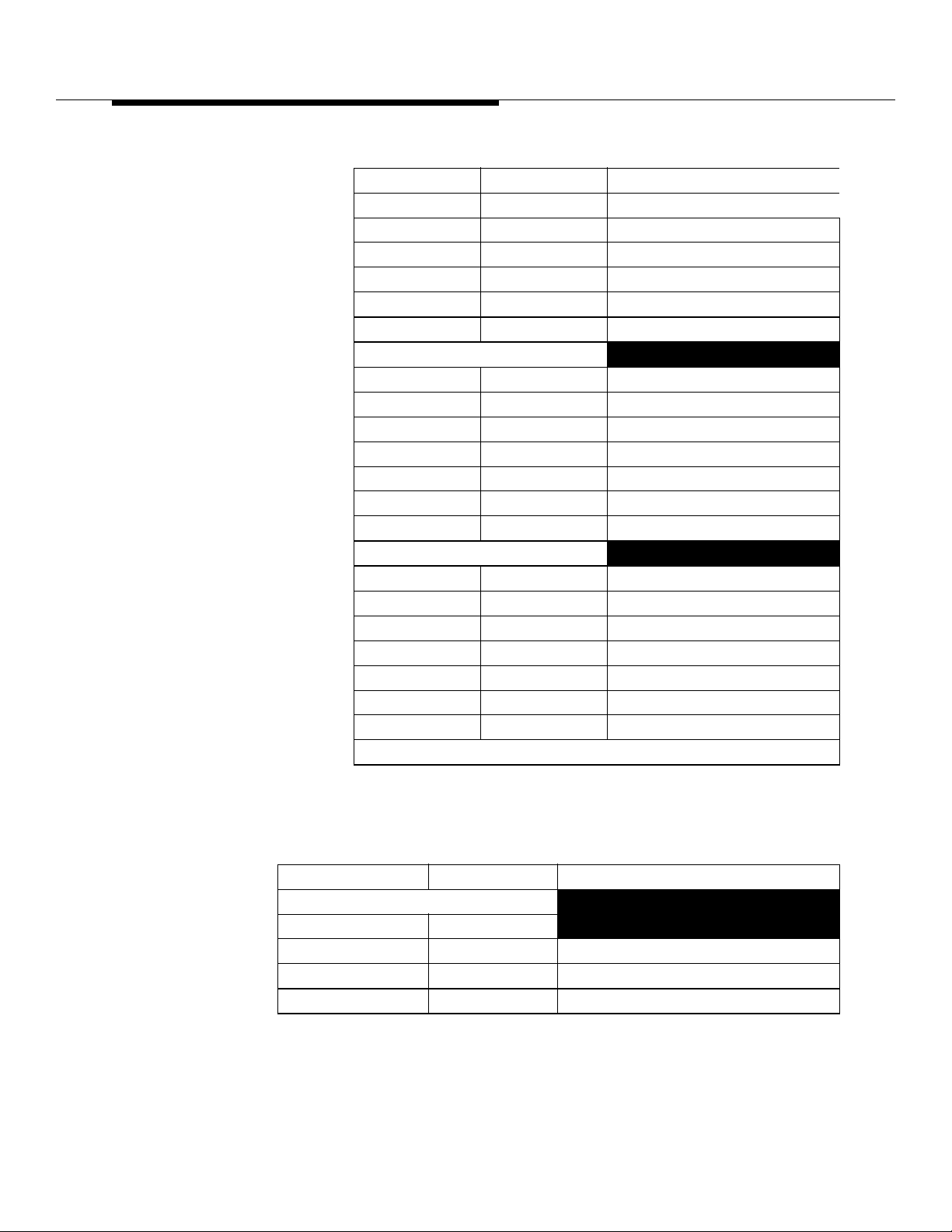
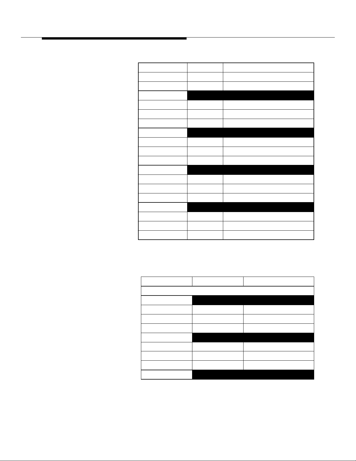
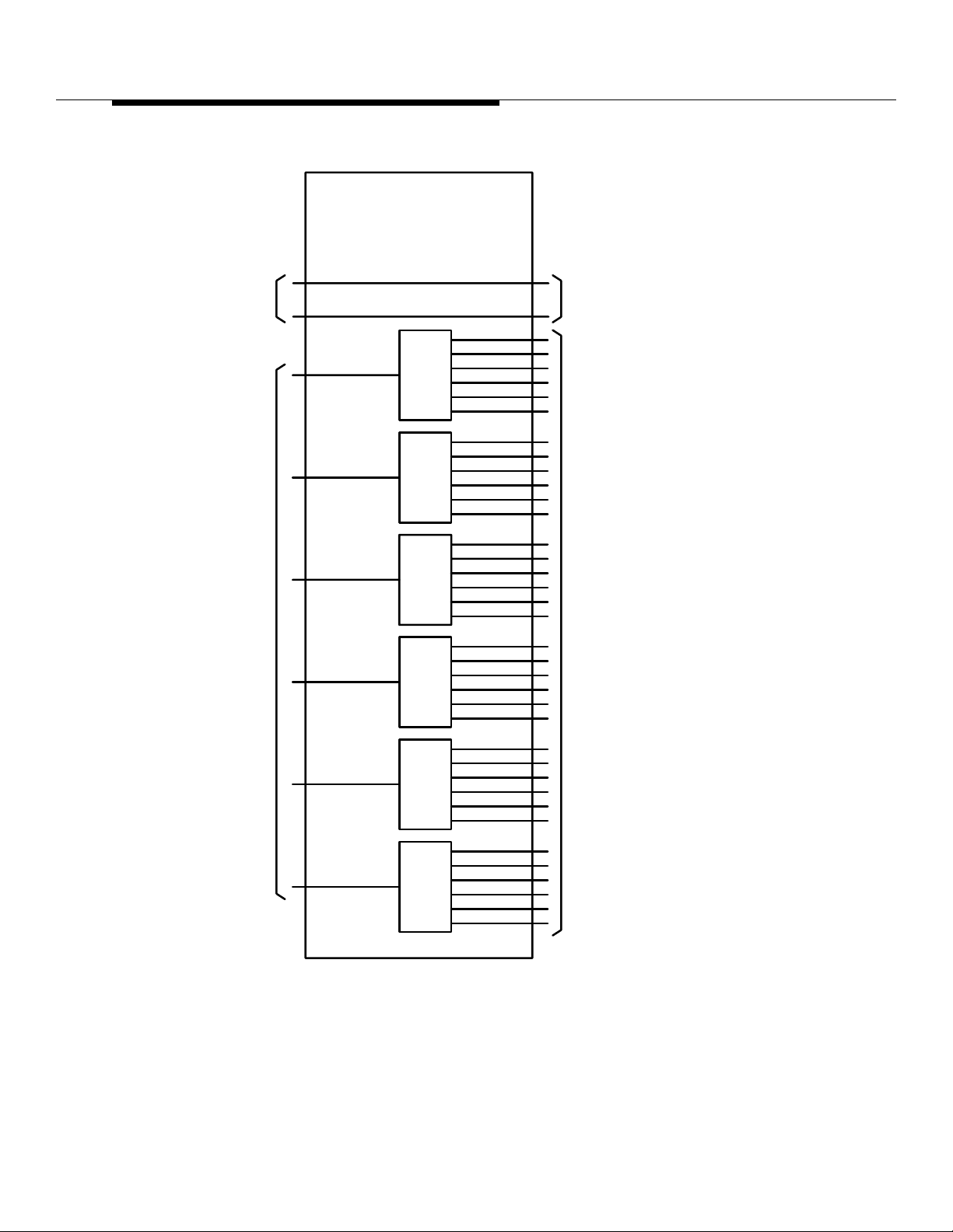
Table 8-4. Radio Channel Frame Interconnection Panel (ED-2R831-30)
Connector Identification (Contd)
Jack (Plug) Conn Type Function
N Tx Antenna 1
1
N Tx Antenna 2
2
N Tx Antenna 3
3
N Tx Antenna 4
4
N Tx Antenna 5
5
N Tx Antenna 6
6
RECEIVE 0 ANTENNA INPUTS
N Rx 0 Antenna 0
0
N Rx 0 Antenna 1
1
N Rx 0 Antenna 2
2
N Rx 0 Antenna 3
3
N Rx 0 Antenna 4
4
N Rx 0 Antenna 5
5
N Rx 0 Antenna 6
6
RECEIVE 1 ANTENNA INPUTS
N Rx 1 Antenna 0
0
N Rx 1 Antenna 1
1
N Rx 1 Antenna 2
2
N Rx 1 Antenna 3
3
N Rx 1 Antenna 4
4
N Rx 1 Antenna 5
5
N Rx 1 Antenna 6
6
†These connectors are not used on the Growth RCF.
8-34
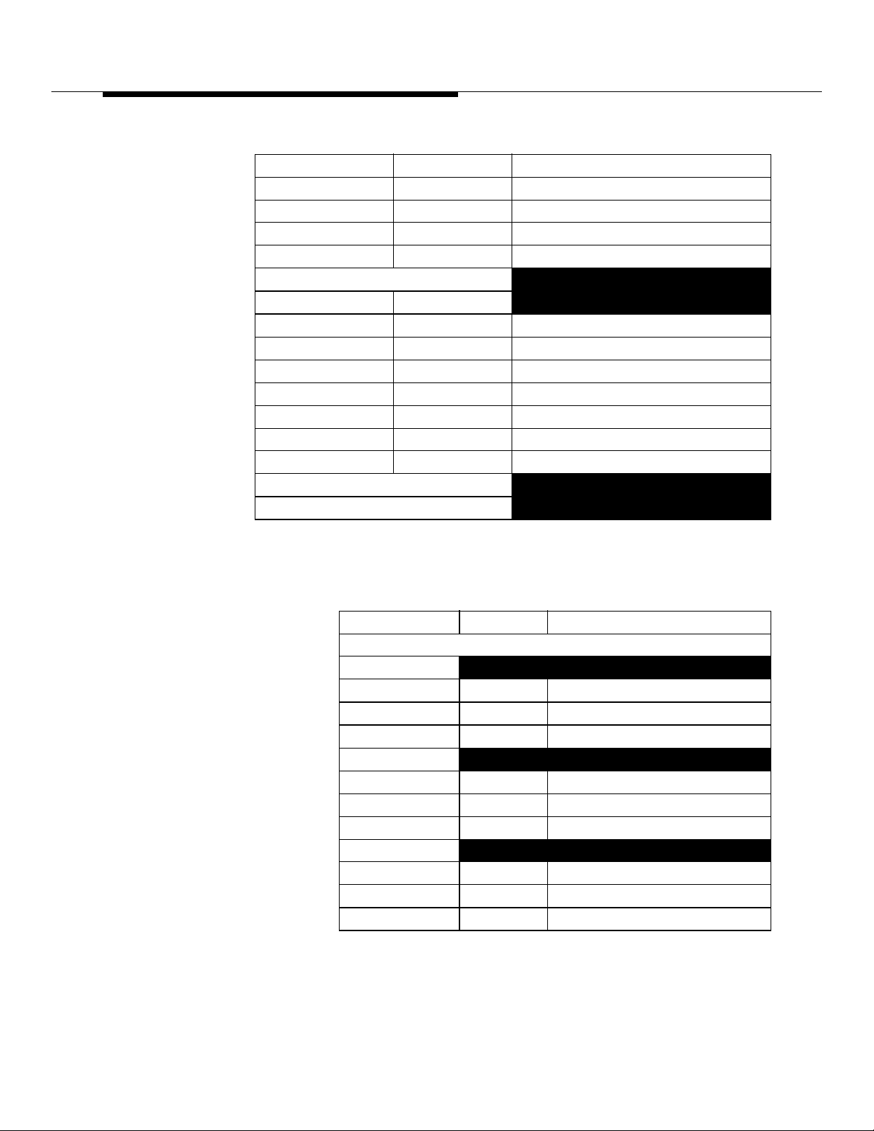
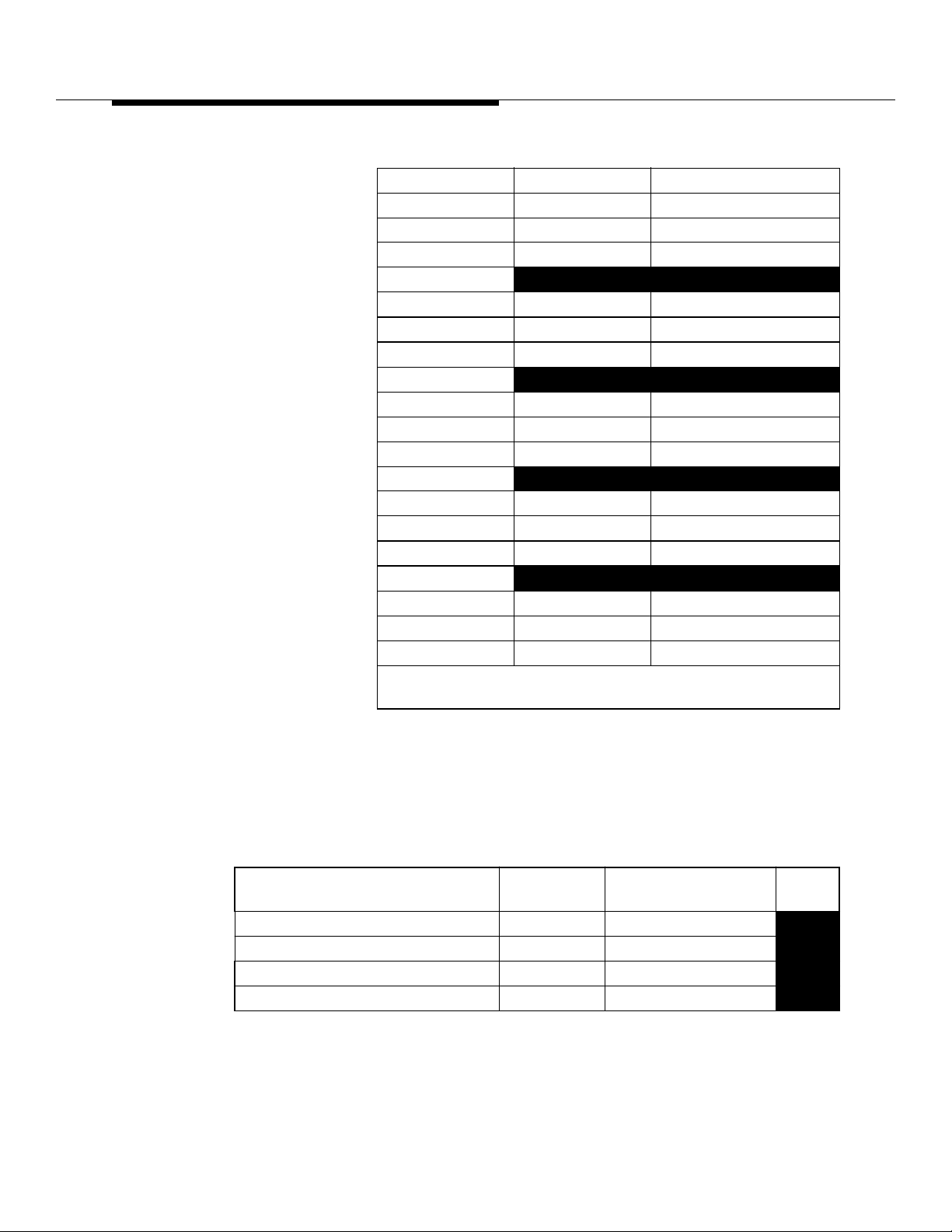
Table 8-5. Radio Channel Frame Interconnection Panel (ED-2R831-30)
Connector Identification
Jack (Plug) Conn Type Function
REFERENCE POWER DIVIDER (1:6)
(PD30)*
REF
COM SMA 15 MHz Reference Input
1 SMA 15 MHz to Shelf 1 PD1
2 SMA 15 MHz to Shelf 2 PD1
Lucent Technologie s — Propriet ary
401-660-100 Issue 11 August 2000
See notice on first page
Page 2
Series II Cell Site Equipment Descriptions
Table 8-5. Radio Channel Frame Interconnection Panel (ED-2R831-30)
Connector Identificat ion (Cont d)
Jack (Plug) Conn Type Function
3 SMA 15 MHz to Shelf 3 PD1
4 SMA 15 MHz to Shelf 4 PD1
5 SMA 15 MHz to Shelf 5 PD1
6 SMA Not Used
REFERENCE POWER DIVIDER (1:6)
(PD30)†
REF
COM SMA 15 MHz Reference Input
1 SMA 15 MHz to Shelf 0 PD1
2 SMA 15 MHz to Shelf 1 PD1
3 SMA 15 MHz to Shelf 2 PD1
4 SMA 15 MHz to Shelf 3 PD1
5 SMA 15 MHz to Shelf 4 PD1
6 SMA 15 MHz to Shelf 5 PD1
* Connections for P-RCF.
† Connections for Growth RCF.
Table 8-6. Radio Channel Frame Interconnection Panel (ED-2R831-30)
Connector Identification
Jack (Plug) Conn Type Function
TRANSMIT ANTENNAS POWER COMBINERS (9:1)
(PD20)
0
J1 SMA Tx Ant 1 Test to Tx SIG MON-0
J2 thru J10 SMA
J11 SMA Tx Output
(PD21)
1
0
J1 SMA Tx Ant 1 Test to Tx SIG MON-1
J2 thru J10 SMA
J11 SMA Tx Output
(PD22)
2
1
J1 SMA Tx Ant 2 Test to Tx SIG MON-2
J2 thru J10 SMA
J11 SMA Tx Output
2
Lucent Technologie s — Propriet ary
See notice on first page
401-660-100 Issue 11 August 2000
8-35
Page 3
Series II Cell Site Equipment Descriptions
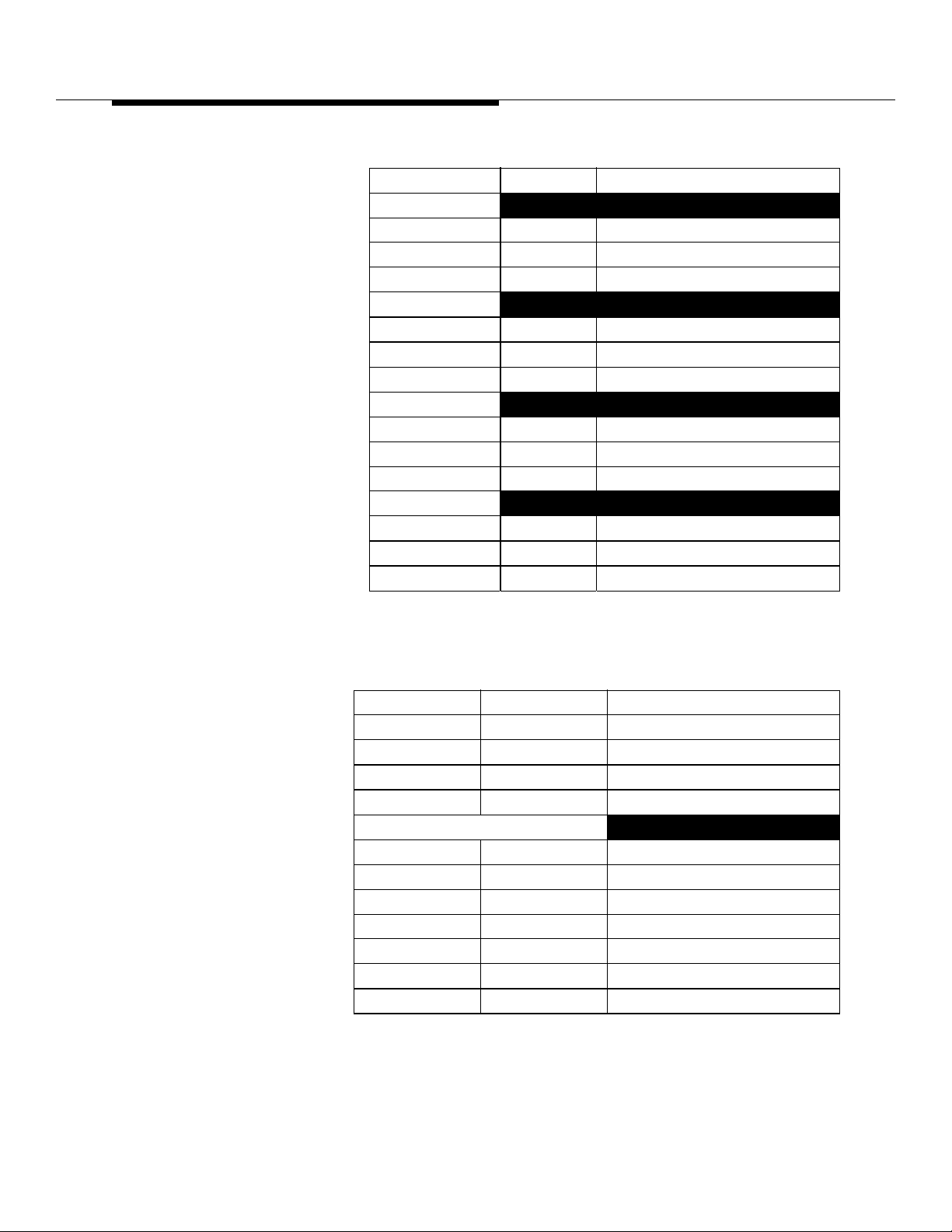
Table 8-6. Radio Channel Frame Interconnection Panel (ED-2R831-30)
Connector Identificat ion (Cont d)
Jack (Plug) Conn Type Function
(PD23)
3
J1 SMA Tx Ant 3 Test to Tx SIG MON-3
J2 thru J10 SMA
J11 SMA Tx Output
(PD24)
4
3
J1 SMA Tx Ant 4 Test to Tx SIG MON-4
J2 thru J10 SMA
J11 SMA Tx Output
(PD25)
5
4
J1 SMA Tx Ant 5 Test to Tx SIG MON-5
J2 thru J10 SMA
J11 SMA Tx Output
(PD26)
6
5
J1 SMA Tx Ant 6 Test to Tx SIG MON-6
J2 thru J10 SMA
J11 SMA Tx Output
6
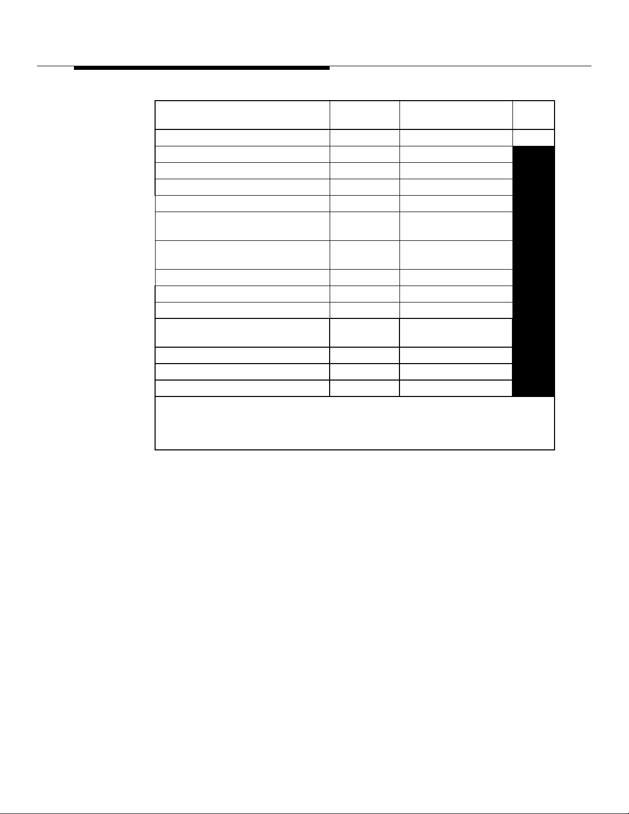
Table 8-7. Radio Channel Frame Interconnection Panel (ED-2R831-30,
Connector Identification
Jack (Plug) Conn Type Function
REF TNC 15 MHz Reference Input
SET UP 0† N Set Up Antenna (for future use)
RTU IN† N Radio Test Unit Input
RTU OUT† N Radio Test Unit Output
TRANSMIT ANTENNA OUTPUTS
N Tx Antenna 0
0
N Tx Antenna 1
1
N Tx Antenna 2
2
N Tx Antenna 3
3
N Tx Antenna 4
4
N Tx Antenna 5
5
N Tx Antenna 6
6
Lucent Technologie s — Propriet ary
See notice on first page
8-36
401-660-100 Issue 11 August 2000
Page 4
Series II Cell Site Equipment Descriptions
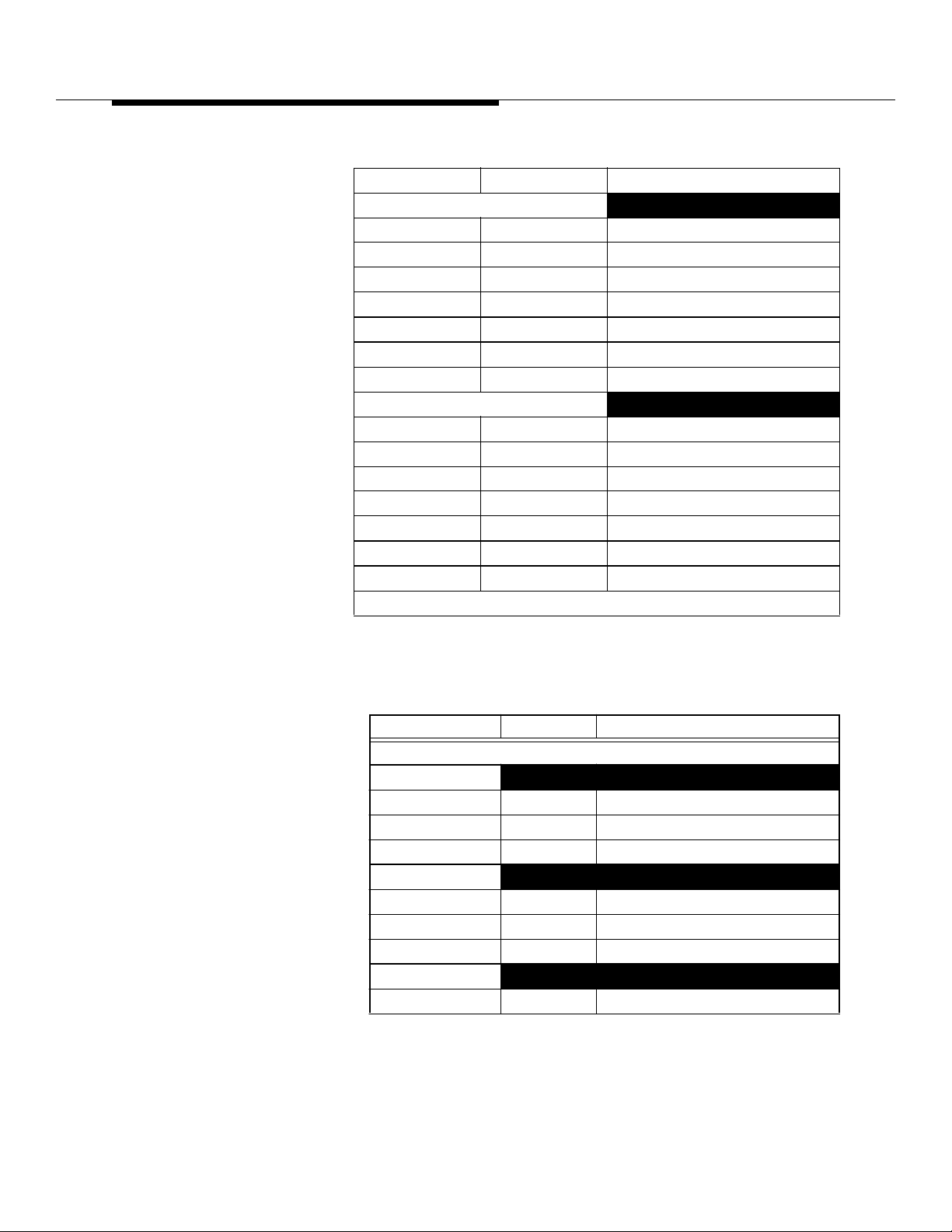
Table 8-7. Radio Channel Frame Interconnection Panel (ED-2R831-30,
Connector Identificat ion (Cont d)
Jack (Plug) Conn Type Function
RECEIVE 0 ANTENNA INPUTS
N Rx 0 Antenna 0
0
N Rx 0 Antenna 1
1
N Rx 0 Antenna 2
2
N Rx 0 Antenna 3
3
N Rx 0 Antenna 4
4
N Rx 0 Antenna 5
5
N Rx 0 Antenna 6
6
RECEIVE 1 ANTENNA INPUTS
N Rx 1 Antenna 0
0
N Rx 1 Antenna 1
1
N Rx 1 Antenna 2
2
N Rx 1 Antenna 3
3
N Rx 1 Antenna 4
4
N Rx 1 Antenna 5
5
N Rx 1 Antenna 6
6
†These connectors are not used on the Growth RCF.
Table 8-8. Radio Channel Frame Interconnection Panel (ED-2R831-30,)
Connector Identification
Jack (Plug) Conn Type Function
RECEIVE 0 ANTENNAS POWER DIVIDERS (1:9)
(PD1)
0
J1 SMA Not Used
J2 thru J10 SMA
J11 SMA Rx 0 Input from 0
(PD2)
1
J1 SMA Not Used
J2 thru J10 SMA
J11 SMA Rx 0 Input from 1
(PD3)
2
J1 SMA Not Used
Lucent Technologie s — Propriet ary
See notice on first page
401-660-100 Issue 11 August 2000
8-37
Page 5
Series II Cell Site Equipment Descriptions
Table 8-8. Radio Channel Frame Interconnection Panel (ED-2R831-30,)
Connector Identification (Contd)
Jack (Plug) Conn Type Function
J2 thru J10 SMA
J11 SMA Rx 0 Input from 2
(PD4)
3
J1 SMA Not Used
J2 thru J10 SMA
J11 SMA Rx 0 Input from 3
(PD5)
4
J1 SMA Not Used
J2 thru J10 SMA
J11 SMA Rx 0 Input from 4
(PD6)
5
J1 SMA Not Used
J2 thru J10 SMA
J11 SMA Rx 0 Input from 5
(PD7)
6
J1 SMA Not Used
J2 thru J10 SMA
J11 SMA Rx 0 Input from 6
8-38
Table 8-9. Radio Channel Frame Interconnection Panel (ED-2R831-30,)
Connector Identification
Jack (Plug) Conn Type Function
Lucent Technologie s — Propriet ary
401-660-100 Issue 11 August 2000
RECEIVE 1 ANTENNAS POWER DIVIDERS (1:9)
(PD11)
0
J1 SMA Not Used
J2 thru J10 SMA
J11 SMA Rx 1 Input from 0
(PD12)
1
J1 SMA Not Used
J2 thru J10 SMA
J11 SMA Rx 1 Input from 1
(PD13)
2
See notice on first page
Page 6
Series II Cell Site Equipment Descriptions
Table 8-9. Radio Channel Frame Interconnection Panel (ED-2R831-30,)
Connector Identification (Contd)
Jack (Plug) Conn Type Function
Note:
01 (P-RCF) or SD-2R264-01 (Growth RCF).
J1 SMA Not Used
J2 thru J10 SMA
J11 SMA Rx 1 Input from 2
(PD14)
3
J1 SMA Not Used
J2 thru J10 SMA
J11 SMA Rx 1 Input from 3
(PD15)
4
J1 SMA Not Used
J2 thru J10 SMA
J11 SMA Rx 1 Input from 4
(PD16)
5
J1 SMA Not Used
J2 thru J10 SMA
J11 SMA Rx 1 Input from 5
(PD17)
6
J1 SMA Not Used
J2 thru J10 SMA
J11 SMA Rx 1 Input from 6
For other transmit and receive options, refer to SD-2R263-
Series II Cell Site
Busbar Assembly
Unit, KS24355, L1
The Cell Site Busbar Assembl y Unit utiliz es plug-in Circu it Break ers f or 5.0 A, 15.0
A, and 25.0 A. It also uses screw-in Capacitors. This unit equips the growth RCF
so that it can support 8 EDRUs per shelf.
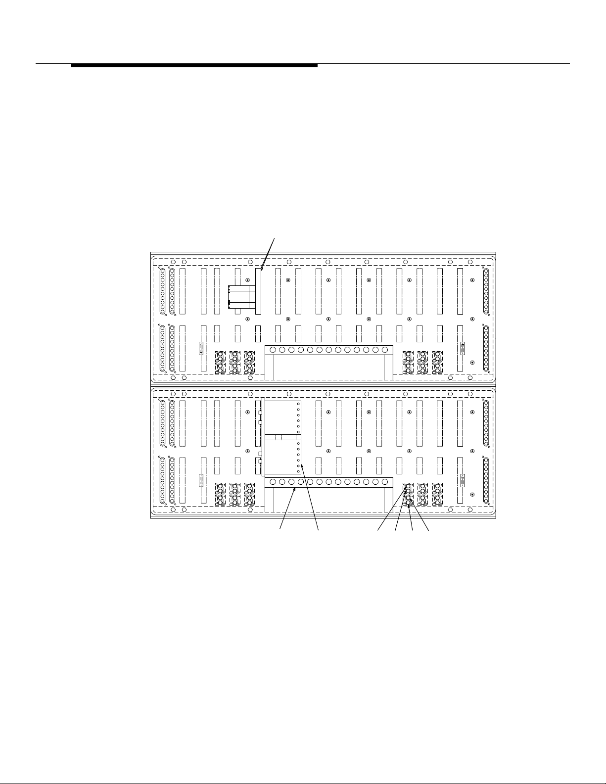
The Growth Channel Fram e Hardware is listed in the table below.
Table 8-10. Growth Radio Channel Frame (G-RCF) J41660B-2 Hardware
Max
Item
Cable Tray Assembly 1
Interconnection Panel 1 ED-2R831-30
Tx, Rx Power Dividers (9:1) 21 KS24235, L5
Tx, Rx Power Dividers (1:6) KS24235, L6
Lucent Technologie s — Propriet ary
See notice on first page
Qty Code
401-660-100 Issue 11 August 2000
Eqpt
Loc
8-39
Page 7
Series II Cell Site Equipment Descriptions
Table 8-10. Growth Radio Channel Frame (G-RCF) J41660B-2 Hardware
Item
Max
Qty Code
Eqpt
Loc
Radio Channel Unit Shelf (Shelf 0-5) 6 ED-2R834-30 13, 21
Transmit Combiner 1 BBN2B
+12V Power Converter 1 419AE
Radio Channel Unit 12 ED-2R836-30
Digital Radio Unit 6 ED-2R920-30
Power Converter Unit 430AB
(Req’d for EDRU)
Enhanced Digital Radio Unit Maximum 12
44WR8
per shelf
Digital Facilities Interface (DFI) 1 TN1713B or TN3500B
+5V Converter 1 430AB
Receive Switch Divider (Manual) 2 BBN1
*Busbar Assembly Unit
2 KS24355, L1
(Manufactured 5/98 or later)
Circuit Breaker, Plug-In, 15.0 A 2 KS24356, L6
Circuit Breaker, Plug-In, 25.0 A 10 KS24356, L8
Circuit Breaker, Plug-In, 5.0 A 3 KS24356, L4
This table is for hardware identif ication only. Do
Note:
use this table for ordering
not
hardware items.
* Replaces Circuit Breaker Assembly ED-2R826-30
and Capacitor Panel Assembly ED-2R829-30.
8-40
Lucent Technologie s — Propriet ary
See notice on first page
401-660-100 Issue 11 August 2000
Page 8

Series II Cell Site Equipment Descriptions
Series II Mobile Switching Center
(MSC) Interface
Two data links provide the contr ol and reporting interface between the Cell Site
and Mobile Switching Center (MSC). Either data link can control Cell Site
functions through the Radio Control Complex (RCC). Each data link interfaces
both of the processors located on the RCC. Only one processor is on-line at a
time. The other is in a standby mode, tracking functions being performed by the
on-line processor, in the event it is required to come on-line.
The on-line processor sends and receives control and data information over the
Time Division Multiplexed (TDM) bus, which is always installed "red stripe up."
Functions performed by the Cell Site units are controlled over the TDM bus . The
on-line processor also supplies data and control to each of the Radio Channel
Unit (RCUs).
Series II Cell Site architecture consists of three types of equipment frames:
1.
Radio Channel Frame (RCF)
frames
2.
Linear Amplifier Frame (LAF)
3.
Antenna Interface Frame (AIF)
The P-RCF contains the Radio Channel Comple x (RCC) as wel l as the shelv es f or
individual TDMA radios. The RCC controls the operation of the Cell Site
equipment. The LAF provides RF signal combining and amplification equipment,
while the AIF houses the Cell Site's reference frequency generator , receiver
calibration generator, and the RF filter networks that transport the RF signal to
and from the antennas.
A Radio Frame Set (RFS) consists of one, tw o, or three RCFs, all controlled by
one RCC. There will be one or two LAFs and one or tw o AIFs per Cell Site. Note
that each of th e three RCFs may contain Digital Radi o Units (DR U s) or Enhanced
Digital Radio Units (EDRUs) . The DRU or EDRU is the radio unit used with Series
II TDMA. The DRU can be configured as a Voice radio (V-DRU) or a Locate radio
(L-DR U). One DRU occupies two analog Radio Channel Unit (RCU) slots and
provides th ree Di gital Tr aff ic Channe ls ( DTCs). One EDRU occupies a single RCU
slot and also provides three DTCs. The EDRU can be configured as a Contr ol/
Traffic (C/T-EDRU) or as an L-EDRU.
Series II analog hardware frames. DRUs, EDRUs, and th e TDMA radio hardware ,
can reside in the same Series II Cell Site RCFs as the analog 30-kHz RCUs.
Hardware wise, converting from Series II Cell Site with analog radios to Series II
TDMA radios is quite simple. For Series II TDMA, the plug-in DRUs and EDRUs
— Primary and a maximum of two growth
— Two frames, maximum
— Two frames, maximu m .
Lucent Technologie s — Propriet ary
See notice on first page
401-660-100 Issue 11 August 2000
8-41
Page 9
Series II Cell Site Equipment Descriptions
are added in the existi ng radio slots in the RFS. Note that it takes two RCU slots
for each DRU.
However, one DRU using a single carrier frequency supports three channels,
while the RCU (analog unit) using a single car rier frequency supports only one
channel. Note also, that an EDRU can perform all the same functions, and more,
of a DRU and tak es up only one RCU slot. DR Us and EDR Us ma y be added to the
Series II Cell Site by replacing existing RCUs with DRUs or EDRUs. Additionally,
one TDMA Radio Test Unit (TRTU) and one (analog) Radio Test Unit (RTU)
Control Board (see Figure 8-12) are required for each digitally equipped Cell Site.
RTU
CONTROL
BOARD
EQL 012EQL 162
+V 1 2 3
RTN
+V
RCU/DRU
REF FREQ.
RTN
123
444
REAR VIEW
RCU
RCU
RCU
RTU
SWITCH
RCU
TRANSMIT
REF.
FREQ.
REC1
REC0
EQL 012EQL 162
Figure 8-12. Radio Test Unit (RTU) Control Board (AYD8) and Switch
Assembly (ED3R026-30) Location
LEVEL 30
(SHELF 30
LEVEL 21
(SHELF 4)
8-42
The Series II Cell Site is based on a modular architecture. It includes controllers,
radios, wideband li near amplifiers, antennas, and associated equipment for
Lucent Technologie s — Propriet ary
See notice on first page
401-660-100 Issue 11 August 2000
Page 10

Series II Cell Site Equipment Descriptions
setting up and completing cellular calls. It can support AMPS, TDMA, and CDMA
simultaneously through the same wideband linear amplifier and antennas.
The AMPS radio consists of a single pl ug-in unit —the radi o channe l unit (RCU) or
the single-board RCU (SBRCU); either unit occupies one RCU slot. (The RCU
consists of two circuit boards, and the SBRCU consists of a single circui t boar d.
The RCU faceplate is wider than the SBRCU fac eplate.) Si milarly, the TDMA radio
consists of a singl e pl ug-in uni t, t he di gital r adio uni t (DRU) or the enhanced digital
radio unit (EDRU); the DRU occup ies two adjoining RCU slots, and the EDR U
occupies one RCU slot. In contrast , the CDMA radio consists of an entire shelf of
plug-in units.
Lucent Technologie s — Propriet ary
See notice on first page
401-660-100 Issue 11 August 2000
8-43
Page 11
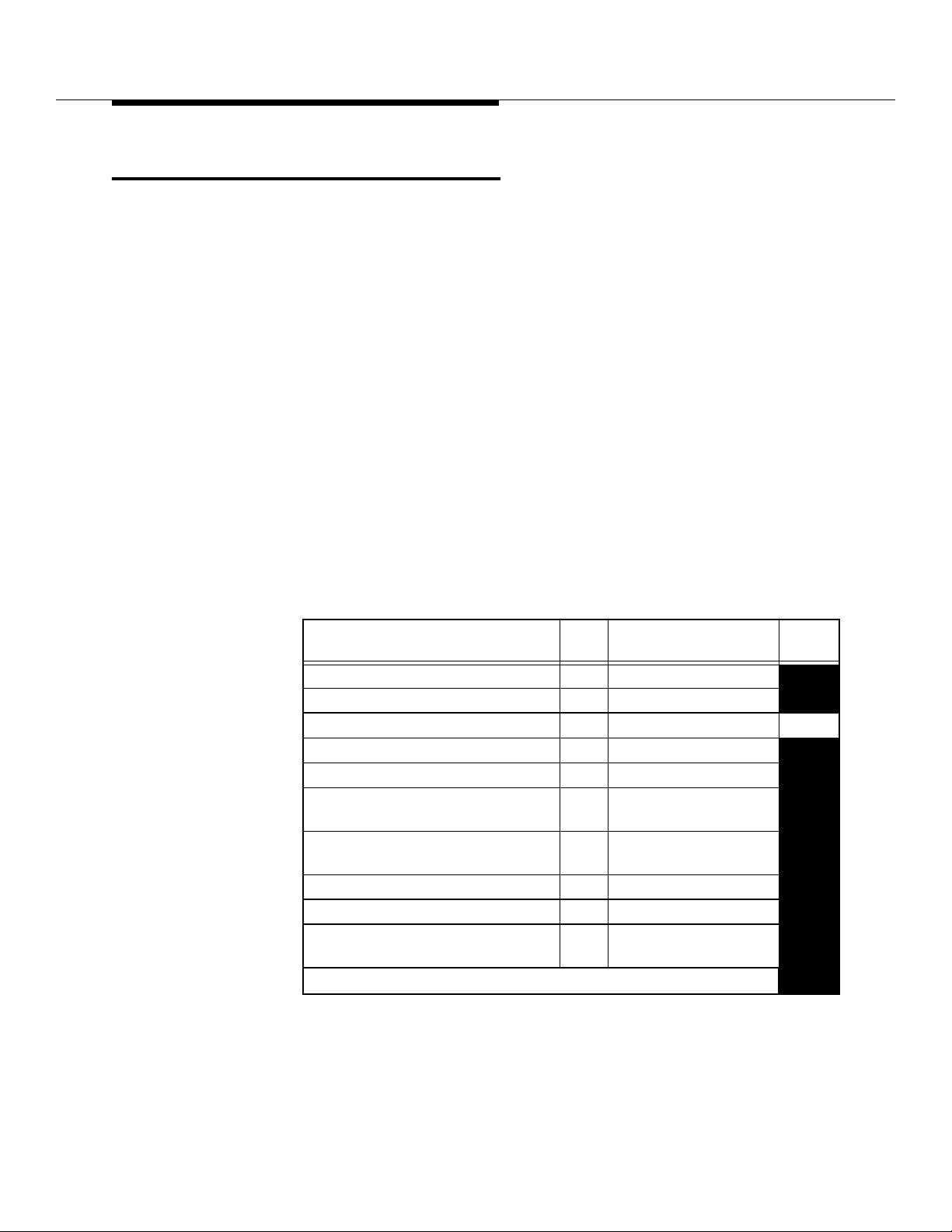
Series II Cell Site Equipment Descriptions
Series II Cell Site Linear Amplifier
Frame (LAF)
The major units of the Linear Amplifier Frame (LAF) are listed below and
described in the paragraphs that follow:
Fr ame Interface Assemb ly (FIA)
■
Linearizer Unit (LZR)
■
Linear Amplifier Unit (LAU).
■
The Linear Amplifier Frame (LAF) is designated as J41660C-1, C-2. All Cell Sites
hav e at leas t one LAF with at lea st one Li near Amplifier Circuit (LA C). Two
different (M)LACs are available depending on the output power needed. They are:
1. 100-Watt (M)LAC uses 10 Linear Amplifier Modules (LAMs).
2. 240-Watt (M)LAC uses 20 LAMs.
Three additional LACs may be configured as needed. A fully loaded LAF (LAF 0)
may contain up to four LACs. An additional LAF, may be added and may be
equipped with up to three LACs.
.
Table 8-11. Linear Amplifier Frame (LAF) Hardware
Max
Item
Qty Code
Linear Amplifier Frame 0 (Primary ) 1 J41660C-1, C-2
Sniffer Combiner (For CDPD) 1 KS21604, L22A
Frame Interface Assembly 1 ED-2R838-30 70
Box Fan 2 WP92103, L1
Linear Amplifier Circuit (LAC) J-41660CA-2, L6 (Full)
Linear Amplifier Circuit (LAC) J-41660CA-2, L5
(Half)
Modular Linear Amplifier Circuit
J-41660CA-3
(MLAC)
RF Amplifier 1 KS23757, L1
Fan Blower 1 WP92104, L1
Linear Amplifier Module‡ 10 or20ED-2R840-30
* Up to three additi onal LACs can be prov i ded in LAF 1.
Eqpt
Loc
8-44
Lucent Technologie s — Propriet ary
See notice on first page
401-660-100 Issue 11 August 2000
Page 12
Series II Cell Site Equipment Descriptions
FRAME
INTERFACE
ASSEMBLY
LEVEL
70
LINEAR
AMPLIFIER
UNIT
LINEARIZER
LINEAR
AMPLIFIER
UNIT
LEVEL
54
LEVEL
28
LEVEL
19
LINEARIZER
LEVEL
10
FRONT VIEWSIDE VIEW
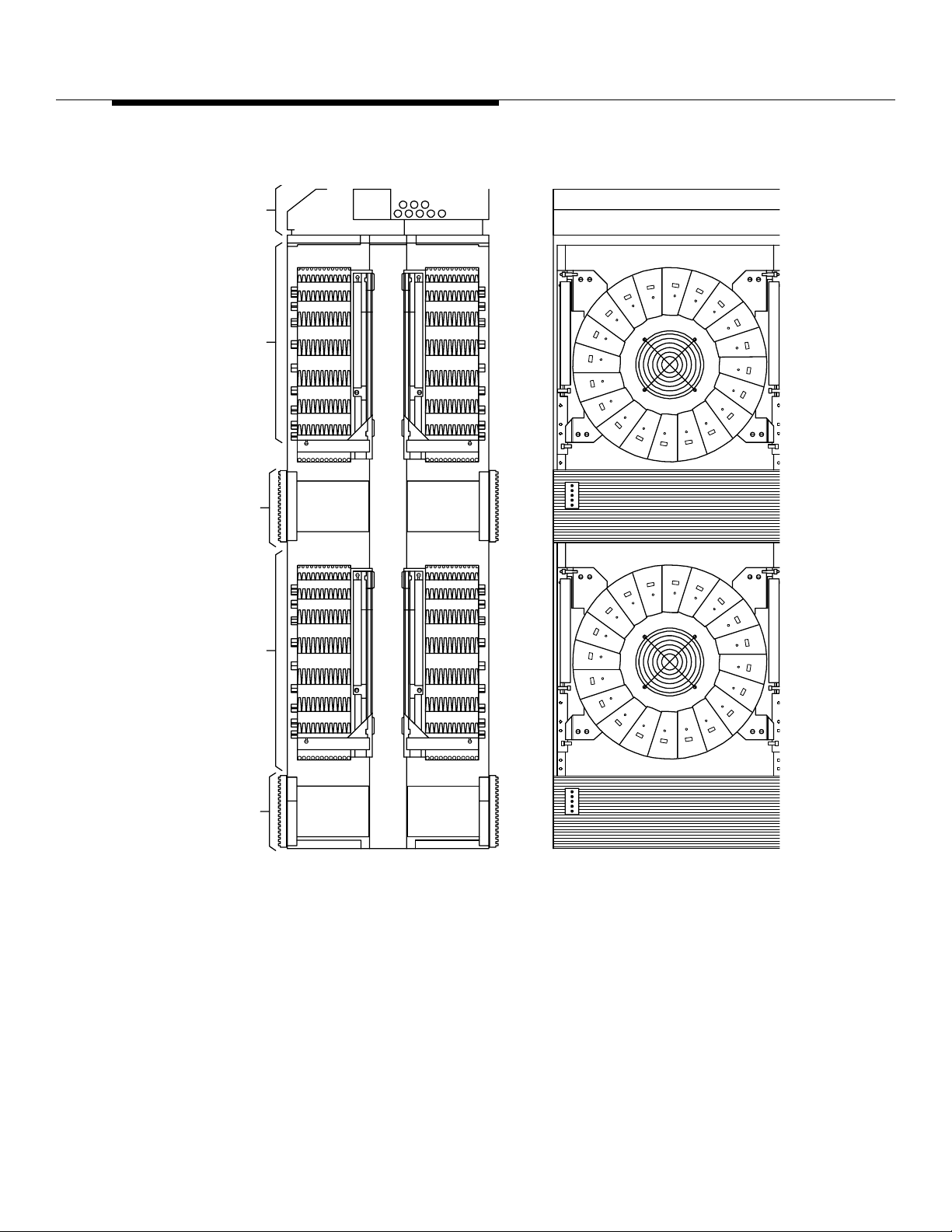
Figure 8-13. Linear Amplifier Frame (LAF) (J41660C-1)
Lucent Technologie s — Propriet ary
See notice on first page
401-660-100 Issue 11 August 2000
8-45
Page 13
Series II Cell Site Equipment Descriptions
CONVERSION RECORD
#LAM DATE CONVERTED
10
20
10
LABEL (MARK DATE
CONVERTED TO 10 LAM
OR 20 LAM LAC)
LINEARIZER (LZR)
(COVER REMOVED)
LINEAR
AMPLIFIER
UNIT (LAU)
20
10
10
SWITCH
(SET TO 10
FOR 10 LAMs,
SET TO 20
FOR 20 LAMs)
LINEAR AMPLIFIER
FRAME (LAF)
20
Series II Cell Site
Linear Amplifier
Circuit J41660CA-1
LINEAR AMPLIFIER
CIRCUIT (LAC)
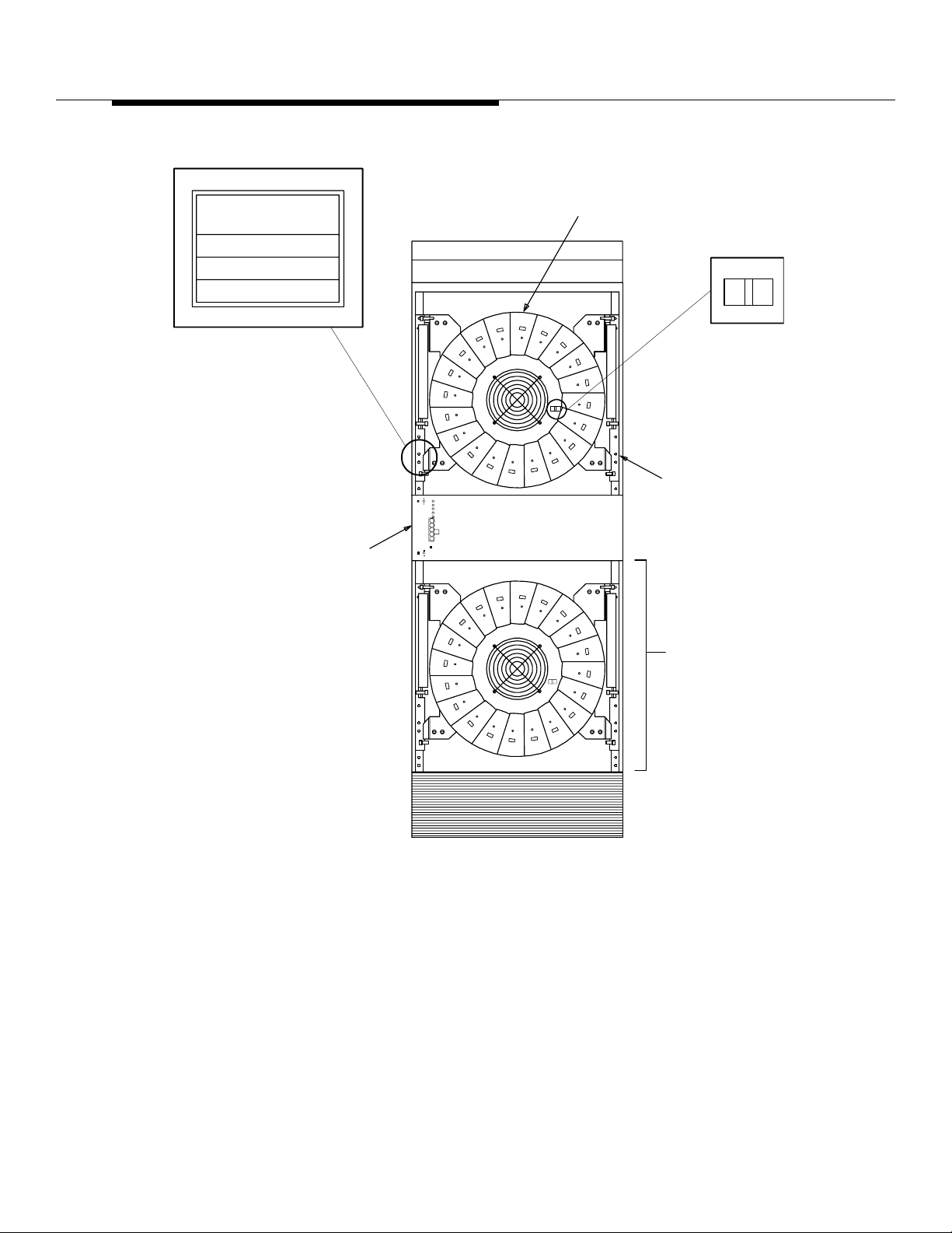
Figure 8-14. Linear Amplifier Frame (LAF) (Doors Removed)
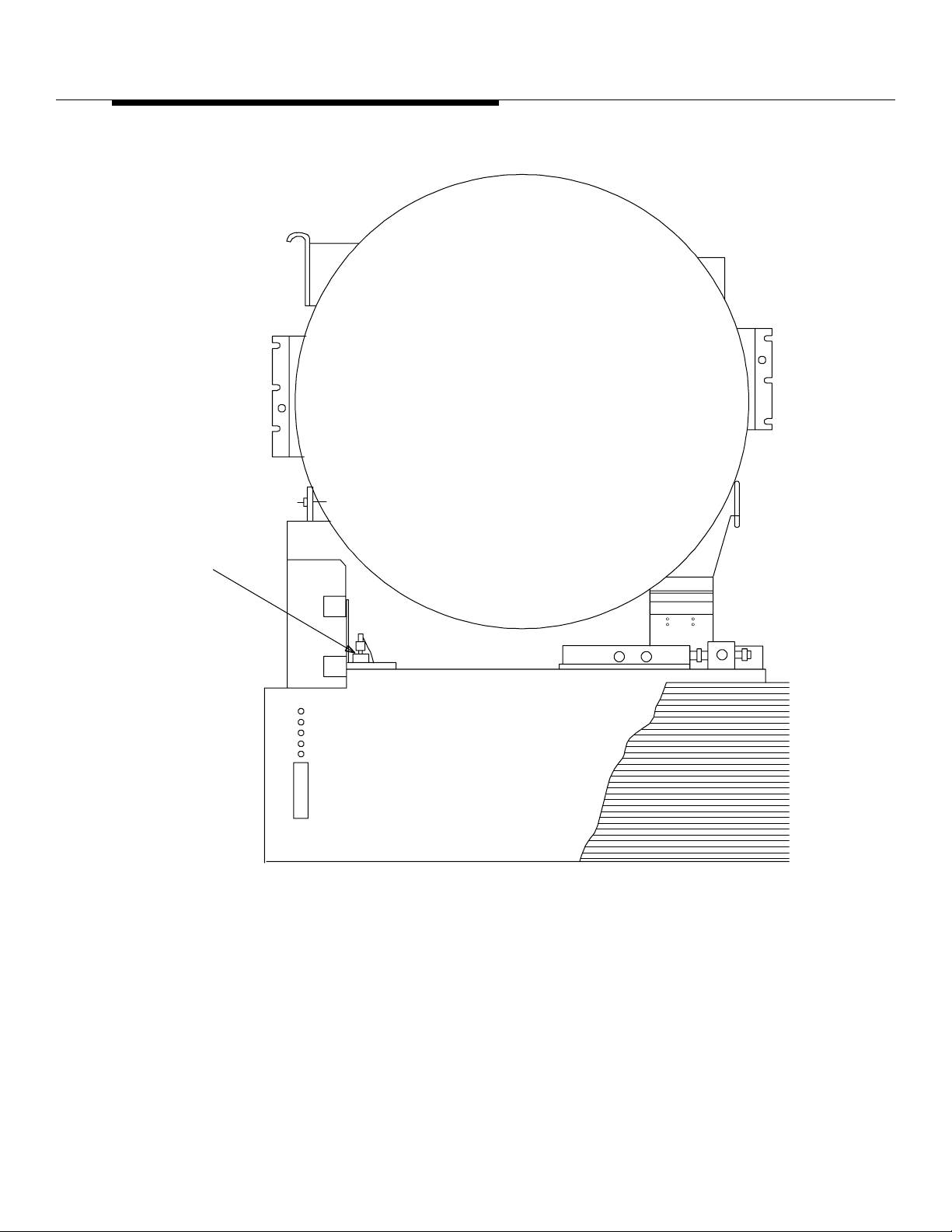
The Linear Amplifier Unit (ED-2R839- 30) and the Linearizer Unit (ED-2R841-30)
make up a Linear Amplifier Circui t (LAC) (see Figure 8-15). Up to four LACs ma y
be used. The Linear Amplifier Unit (LAU) has either 10 or 20 pie-shaped Linear
Amplifier Modules (ED-2R840-30) operating in paral lel. When all Linear Amplifier
Modules (LAMs) are equipped, the maximum average output power is 240 watts.
Lucent Technologie s — Propriet ary
See notice on first page
8-46
401-660-100 Issue 11 August 2000
Page 14

Series II Cell Site Equipment Descriptions
The LAU has a power distribution board (AYM1), a 24-volt pow er filter, a cooling
fan, and a temperature sensor. The output from the LAU is applied to the antenna
interface frame. A splitter combiner assembly is also part of the LAU.
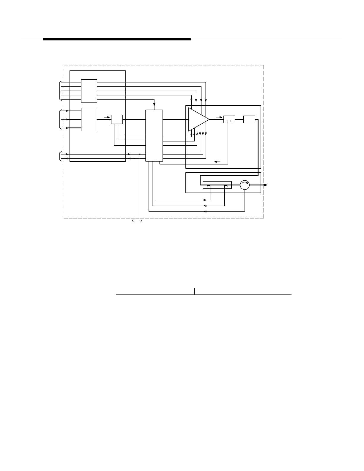
The term Linear Amplifier Circuit (LAC) (see Figure 8-16) is used to include all
major functional p arts of the Linear Amplif ier Frame (LAF). The LAC pr ovi des high
power amplification of many transmit signals and controls the intermodulation
distortion. The LAC consists of the following:
Combiner-Preamplifier Circuit
■
Linear Amplifier Unit (LAU)
■
Linearizer (LZR).
■
Transmit signals originating at the RCF(s) are combined and amplified to a level
suitable for driving the input of the LZR. The LZR uses feed-forward, predistortion, and amplification of the input si gnal to cancel distortion and provides a
level necessary for driving the LAU. The LZR provides continuous control of gain
and phase to provide maximum distortion reduction. It also provides fault
detection, power distribution, and overload protection for the LAC.
The LAU consists of 10 or 20 LAMs arranged in parallel, a splitter-combiner
network, and a power distribution board. It amplifies t he input signal to an output
level of 240 watts when fully configured with 20 LAMs (approximately 120 watts
when equipped with 10 LAMs). The +24 volt DC from the Cell Site power plant is
applied to the fi lt er capacitor bank in the FIA. From here, power feeders 0 through
3 supply +24 volt DC to the LAU and power feeder 4 supplies +24 volt DC to the
LZR fan and to the Power Fault Monito r (PFM) board inside the LZR.
Lucent Technologie s — Propriet ary
See notice on first page
401-660-100 Issue 11 August 2000
8-47
Page 15
Series II Cell Site Equipment Descriptions
YF4
Figure 8-15. Li near Amplifier Circuit (LAC), Front View
The PFM board supplies +24 volt DC to the fan in the LAU; it also converts the
+24 volt DC to +5 and ±15 volt DC and applies these to the LAU.
8-48
Lucent Technologie s — Propriet ary
See notice on first page
401-660-100 Issue 11 August 2000
Page 16

Series II Cell Site Equipment Descriptions
The PFM board distributes the gain and phase adjustment signals between
various circuit boards in the LZR. It also monitors the fault status of the fans,
LAMs, and the LZR internal circuits. The fault status is processed and passed to
the AFI board in RCF0. When a critical fault condition occurs (for example , hig h
temperature), the +5 volt bias to the LAU shuts down. This turns the LAU off and
takes that particular LAC out of service. The fault condition continues to be
monitored and the LAC put back into service automatically if the condition is
cleared.
The PFM board also measures a portion of the LA C Radio Frequency (RF) output
signal level (TX signal loop 2). If the measurement is too high, the PFM sends an
attenuator control signal to the attenuator in the preamplifier to lower its gain.
Transmit signals from t he RCF(s) are co nnect ed to one o r more of the th ree inputs
of the 3:1 power combiner located in the FIA. Each input has an adjustable
attenuator for equalizing the RF path loss between the RCF(s) and the LAC
combiner input. The combiner output is connected to the input of the preamplifier
where the signal is amplified b y 40 to 50 dB. The preamplifier has an e xternally
accessible gain control for setting the preamplifier gain, hence, the desired LAC
output power. It also can lower the gain from its set value through a feedbac k
control from the PFM.
The preamplifier has two amplifiers connected in parallel so that a failure within
the preamplifier will no t shut do wn the whol e L A C . The output of t he two ampl ifi ers
is continuously monit ored by the PFM board, and a failure of one is indicated by
an LED on the PFM.
The output of the preamplifier is applied to and distortion correction circ uits in the
LZR. The RF output from the LZR is applied to the LAMs in the LAU, where it is
amplified and applied through 50-dB coupler CP1 and high-power delay line DL2
to 10/50-dB coupler CP2 in the LZR. The 10-dB portion of CP2 is used to inject
the distortion correction signal i nto the main path, while the 50-dB portion is used
to couple off a signal for loop 2. The output of CP2 is coupled to circulator HY1,
which sends the RF signal to the AIF and also sends a reflected TX (Transmi t)
signal back to the LZR.
Lucent Technologie s — Propriet ary
See notice on first page
401-660-100 Issue 11 August 2000
8-49
Page 17
Series II Cell Site Equipment Descriptions
FROM
CELLSITE
+24V DC
SUPPLY
RF
FROM
RCUs
TO/FROM
ALARM/
FITS
BOARD
P/O FRAME INTERFACE ASSEMBLY
(FIA)
FDR 0
FDR 1
FILTER
FDR 2
CAPACITOR
FDR 3
BANK
FDR 4
POWER
COMBINER
3:1
LAF ALARM STATUS REQUEST
LAF ALARM STATUS
ATTEN./
PREAMP
LZR IN
+24 PWR 0
+24 PWR 1
ATTENUATOR
CONTROL
TO LAC (1, 2, 3)
LINEAR AMPLIFIER CIRCUIT
P/O
LZR OUT
LINEARIZER
UNIT
(LZR)
+5V
+15V
+24V FAN
FAN ALARM
TEMP. ALARM
MODULE STATUS
TX SIGNAL
LOOP 1
IDM CORRECTION SIGNAL
TX SIGNAL LOOP 2
REFLECTED TX SIGNAL
P/O
LZR
LINEAR
AMP
LINEAR AMPLIFIER UNIT
(LAU)
CP2
DL2CPI
DELAY
HY1
RF OUT TO
ANTENNA
INTERFACE
FRAME
Figure 8-16. LAC Functional Diagram
Linear Amplifier Circuit (LAC) Drawings
The following list provides the Drawing code numbers for the Linear Amplifier
hardware:
Code Number LAC Drawing
SD2R265-01 Linear Amplifier Circuit
SD2R266-01 Linear Amplifier Frame
SD2R271-01 Series II Cell Site
J41660C Linear Amplifier Frame
J41660CA Linear Amplifier Circuit
ED2R839-30 Linear Amplifier Unit
ED2R840-30 Linear Amplifier Module
ED2R841-30 Linearizer Unit.
Lucent Technologie s — Propriet ary
See notice on first page
8-50
401-660-100 Issue 11 August 2000
Page 18
Series II Cell Site Equipment Descriptions
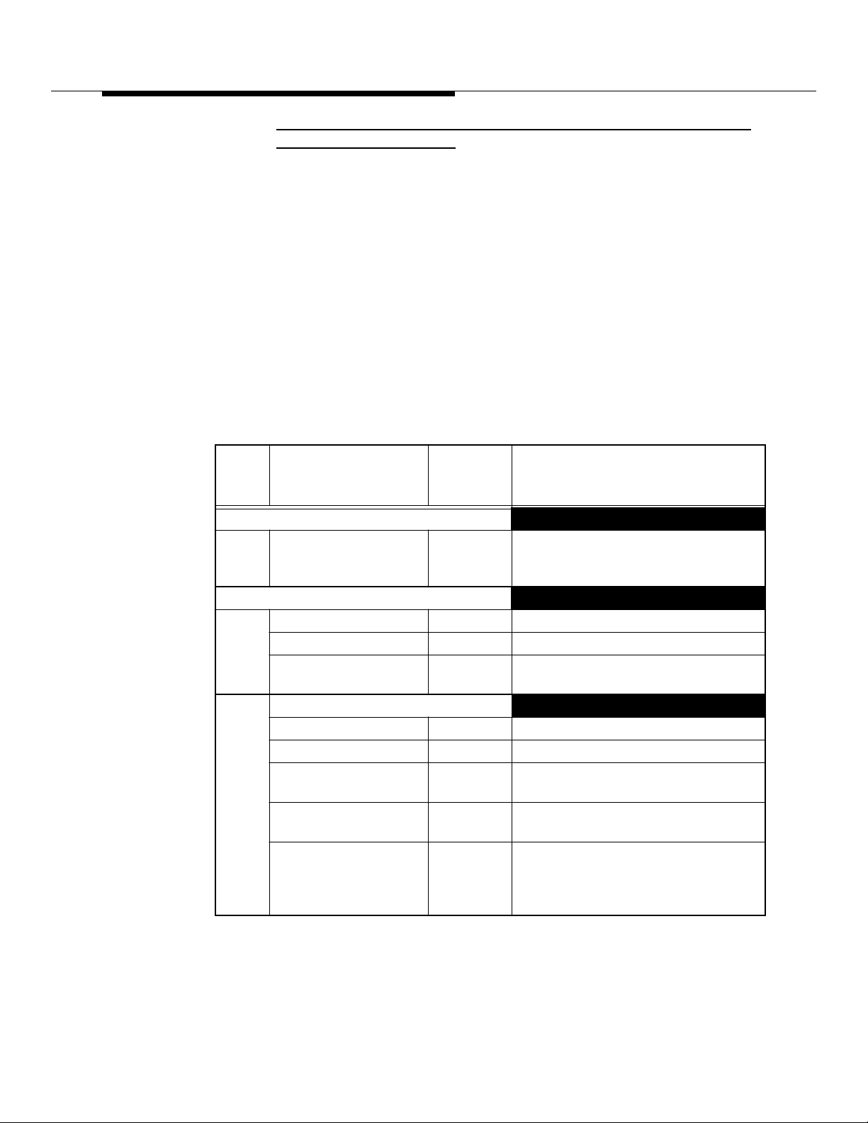
Series II Cell Site, Differences Between A/B-Series and C-Series Linear
Amplifier Circuits (LACs) 0
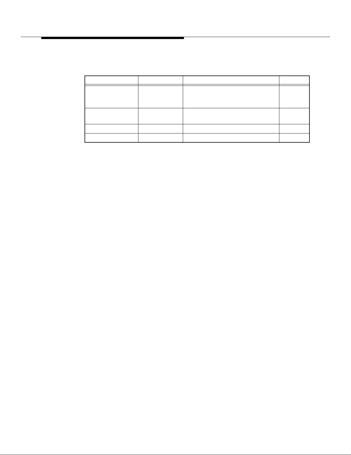
This section des cribes the diff erences in alarm reporting between A/ B-Series and
C-Series Linear Amplifier Circuits (LACs). A description of LAC LED indicators
(See Table 8-12, and Table 8-13) and field replaceable fuses is also provided.
C-Series LACs provide improved power circuit ry and alarm indications. C-Series
LACs are most easily distinguishable from A/B-Series LAC s by the presence of
the 10/20 LAM Switch on the circular po wer distributi on (AYM) board on the Linear
Amplifier Unit (LAU).
For additi onal information, consult Lucent Technologies Customer Inf ormation
Bulletin 196A, "Improved "C" Linear Amplifier Circuit Features."
Table 8-12. Linear Amplifier Frame / Linear Amplifier Circuit (J41660CA-1)
Controls and Indicators
Circui
t Control/
Pack Indicator Type Function
Linear Amplifier Unit ED-2R839-30
AYM3 DS1-DS20 LED (Red) Indicates +24-volt power failure t o
Linearizer ED-2R841-30
AYE1 SW1 Sets address of the LAC.
SW2 Factory/field switch.
SW3
SW4
AYG1 STATUS
Input Drive LED (Red) Indicates a problem with the RF input.
Fans LED (Red) Indicates a fan failure.
Preamplifier LED (Red) Indicates one or both input
Linear Amplifier Unit LED (Red) Indicates a fan failure, high tempera-
Linearizer LED (Red) Indicat es a fan fai lure, power supply
the associated Linear Amplifier
Module.
Supplies pilot signal to the Gain
Phase Adjuster AYF1.
preamplifiers have failed.
ture, or LAM failures in the LAU.
failure, or excessive intermodulation
distortion
in the Linearizer.
Lucent Technologie s — Propriet ary
See notice on first page
401-660-100 Issue 11 August 2000
8-51
Page 19
Series II Cell Site Equipment Descriptions
Table 8-13. Linear Amplifier Frame / Linear Amplifier Circuit (J41660CA-1)
Fuses
Fuse Designation Voltage Supplied To Circuit Location
LINEAR
AMPLIFIER UNIT
FAN
PREAMPLIFIER F10, 2A, +24V
F11, 2A, +24V
LINEARIZER FAN F12, 3A, +24V Fan B1 in the Linearizer by TB1 10, 28
FCA F13, 10A, +24V AYH2 board in the Linearizer 10, 28
F9, 5A, +24V Fan B2 in the LAU by Te mp. Sensor
EAP1 and filter FL1
Attenuator Preamplifier PA1
in the Linearizer
19, 54
10, 28
Series II Cell Site
Linear Amplifier
Module ED-2R84030
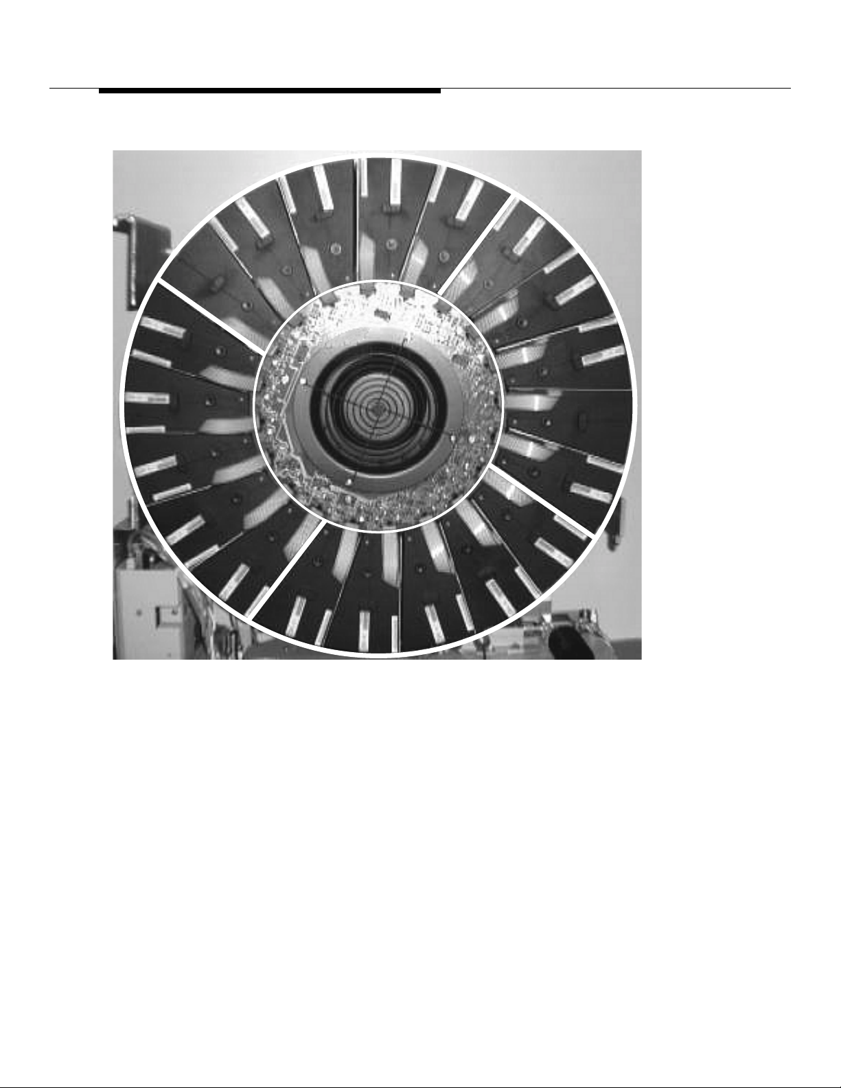
The Linear Amplifier Unit (LAU) is capable of handling 20 Linear Amplifier
Modules (LAMs) (See Figure 8-17). Tw o sets of 10 modules must be used — one
set may be non-amplifying modules.
8-52
Lucent Technologie s — Propriet ary
See notice on first page
401-660-100 Issue 11 August 2000
Page 20
Series II Cell Site Equipment Descriptions
Series II Cell Site
Linear Amplifier
Unit (LAU)
Figure 8-17. Linear Amplifier Module (LAM)
The Linear Amplifier Unit (LAU) (see Figure 8-18) receives the Radio Frequency
(RF) output from the linearizer unit (LZR) and applies it to an Linear Amplifier
Module (LAM) where it is amplified and then processed out to the Antenna
Lucent Technologie s — Propriet ary
See notice on first page
401-660-100 Issue 11 August 2000
8-53
Page 21
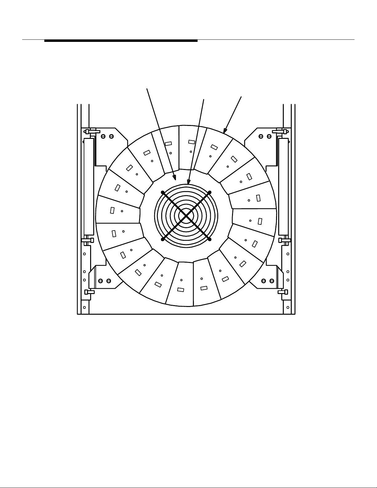
Series II Cell Site Equipment Descriptions
Interface Fr ame (AIF) . The LAU also cont ains a cooling fan and a tempera tur e
sensor (overheat sensor).
PRINTED WIRING
BOARD AYM3
FAN
LINEAR AMPLIFIER
MODULE
ED-2R840-30
8-54
FRONT VIEW
Figure 8-18. Li near Amplifier Unit ED-2R839-30
Lucent Technologie s — Propriet ary
See notice on first page
401-660-100 Issue 11 August 2000
Page 22
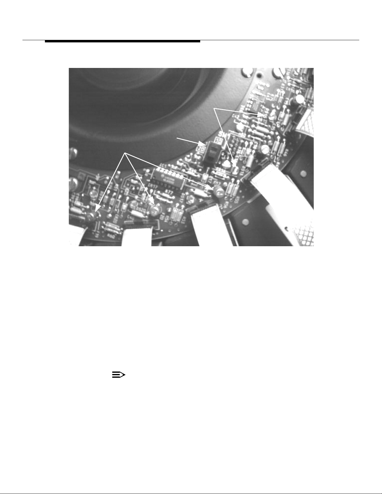
Series II Cell Site Equipment Descriptions
LAM
FUSES
LAM
LEDs
10/20
SWITCH
Series II Cell Site,
20-LAM LAC
Vers u s 10-LAM
LAC
Figure 8-19. Location of LAM Fuses, LEDs, and the 10/20 Switch (on C-Series
LACs)
When Linear Amplifier Circuits (LACs) are shipped from the factory, they are
configured as full-power (20-LAM) LACs (see Figure 8-19). If they are to be
installed as low-power (10-LAM) LACs, an in-line SMA attenuator must be
installed in Series with a coaxial cable in the Linearizer (LZR) and, on C-Serie s
LACs, the 10/ 20 switch on the front of the circuit AYM board must be changed to
the 10 position. To change back to a 20-L AM LAC, the in-line attenuator must be
removed and the switch returned to the 20 position. A label (CONVERSION
RECORD) is provided on the front face of the Linearizer cabinet on C-Series
LACs and should be marked with the date of any 10/20 conversion. A suitable
label should also be placed on any A/B-Series LACs which are conv erted.
NOTE:
Any new C-Series LACs shipped from the factory as replacements will not
have attenuators. The attenuators may be obtained from Lucent
Technologies as a spare part, Comcode 406825794 or 406822064. Any
Lucent Technologie s — Propriet ary
See notice on first page
401-660-100 Issue 11 August 2000
8-55
Page 23

Series II Cell Site Equipment Descriptions
new C-Series, half-power LA Cs ordered will have the attenuator shipped
loose as part of J41660CA-1, List 3 or J41660CA-2, List 4.
Series II Cell Site
Linearizer Unit
ED-2R841-30
The Linearizer unit (L ZR) (see Figure 8-20, and Figure 8-23) is located in a shelf
below each Linear Amplifier Unit (LAU). The LZR contains circuits that function to
reduce intermodulation distortion. The LZR contains a powe r fault monitor board.
This board monitors faults and sends alarms back to the Radio Control Frame
(RCF).
The Linearizer Unit (LZR) recei ves the combined Radio Frequency (RF) input
from the Fr ame Int erface Assembly (FIA) and functions to reduce the
intermodulation distortion prior to applying the RF input to the Linear Amplif ier
Unit (LAU). The LZR also has circuits to monitor alarm conditions on the Linear
Amplifier (LA F).
8-56
Lucent Technologie s — Propriet ary
See notice on first page
401-660-100 Issue 11 August 2000
Page 24
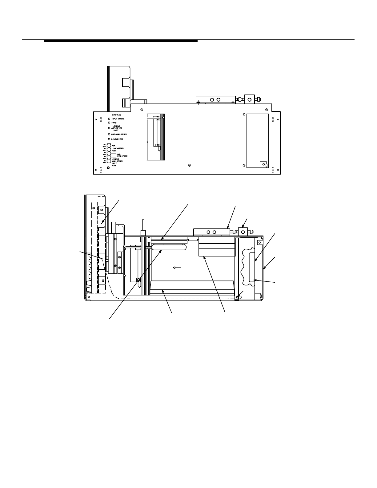
Series II Cell Site Equipment Descriptions
FRONT VIEW
J44
WP-92068, L2
DELAY LINE
KS-14174,L ( )
PIN, DESIGNATION
(FACEPLATE REMOVED FOR CLARITY)
105517155
AYF2
PWB (GAIN PHASE
ADJUSTER 2 (GPA2))
AIR
FLOW
J48
J42
AYH1 PRINTED WIRING
BOARD (PRE-DISTORTION
DRIVER (PDD))
FRONT VIEW
KS-21603, L5
DIRECTIONAL COUPLER
AYH2 PRINTED WIRING BOARD
(FINAL CORRECTION
AMPLIFIER (FCA))
Figure 8-20. Linearizer (LZR) Unit ED-2R841-30
WP-92702, L1
CIRCULATOR
J32
PART OF KIT,
LINEARIZER
846531754
846491843
BRACKET, FAN
PART OF KIT,
LINEARIZER
846531754
846492015
BASE
FAN
Lucent Technologie s — Propriet ary
See notice on first page
401-660-100 Issue 11 August 2000
8-57
Page 25
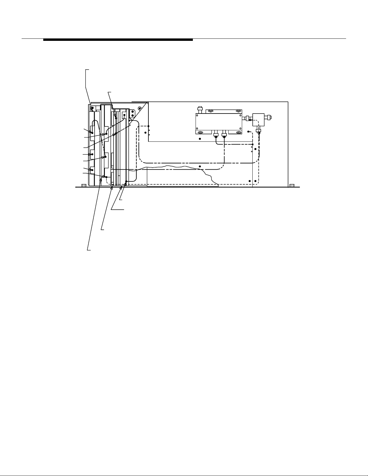
Series II Cell Site Equipment Descriptions
AYG1 PRINTED WIRING
BOARD (POWER FAULT
MONITOR (PFM))
J36
J4
J25
J35
P11
P15
J5
J44
J52
AYE2 PRINTED WIRING
BOARD (RF POWER
SENSOR (RPS))
AYF1 PRINTED WIRING
BOARD (GAIN PHASE
ADJUSTER 1 (GPA1))
AYE1 PRINTED WIRING
BOARD (CONTROLLER/
ANALYZER BOARD (CAB))
J41
TOP VIEW
CP2
-10 -50
HY1
J32
J49
8-58
Figure 8-21. Linea ri zer Unit ED-2R84 1-30
Lucent Technologie s — Propriet ary
See notice on first page
401-660-100 Issue 11 August 2000
Page 26
Series II Cell Site Equipment Descriptions
J10
J3
J51
J50
J45
J47
J38
P14
REAR VIEW
J33
P1
P13
J6
J2
J1
J9
J7
J8
J31
J37
J46
BOTTOM VIEW
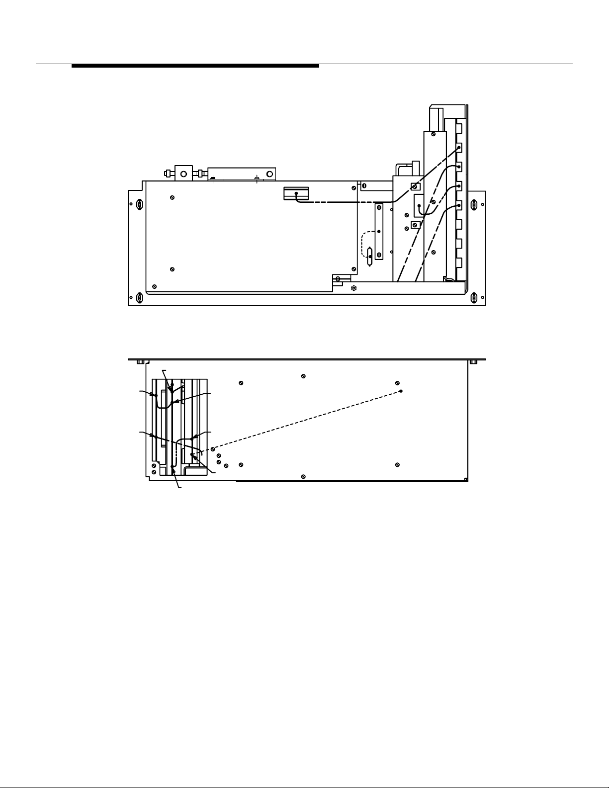
Figure 8-22. Linea ri zer Unit ED-2R84 1-30
Lucent Technologie s — Propriet ary
See notice on first page
401-660-100 Issue 11 August 2000
8-59
Page 27
Series II Cell Site Equipment Descriptions
STATUS
INPUT DRIVE
ANTENNA
LINEAR
AMPLIFIER
UNIT
PRE-AMPLIFIER
LINEARIZER
LINEARIZER
FAN
PRE
AMPLIFIER
LINEAR
AMPLIFIER
UNIT
FAN
10A
24V
3A
24V
2A
24V
2A
24V
5A
24V
STATUS
INPUT DRIVE
FANS
LINEAR
AMPLIFIER
UNIT
PRE-AMPLIFIER
LINEARIZER
FCA
LINEARIZER
FAN
PRE
AMPLIFIER
LINEAR
AMPLIFIER
UNIT
FAN
8-60
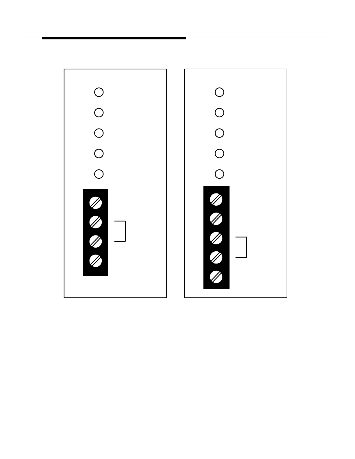
Figure 8-23. Linearizer Faceplate with the Front Grille Removed
Please refer to Lucent Technologies Practice 401-660- 125 for a full description of
the Modular Linear Amplifier Cir cuit (MLAC) J-41660CA-3.
Lucent Technologie s — Propriet ary
See notice on first page
401-660-100 Issue 11 August 2000
Page 28

Series II Cell Site Equipment Descriptions
Series II Cell Site Frame Interface
Assembly ED-2R838-30
The frame inter face assemb ly contai ns the connect ors used to i nterf ace t he Linear
Amplifier Frame (LAF) with the power plant and Radio Channel Frames (RCFs).
Also, this assembly contains 20 capaci tors used to filter the +24 volt supply.
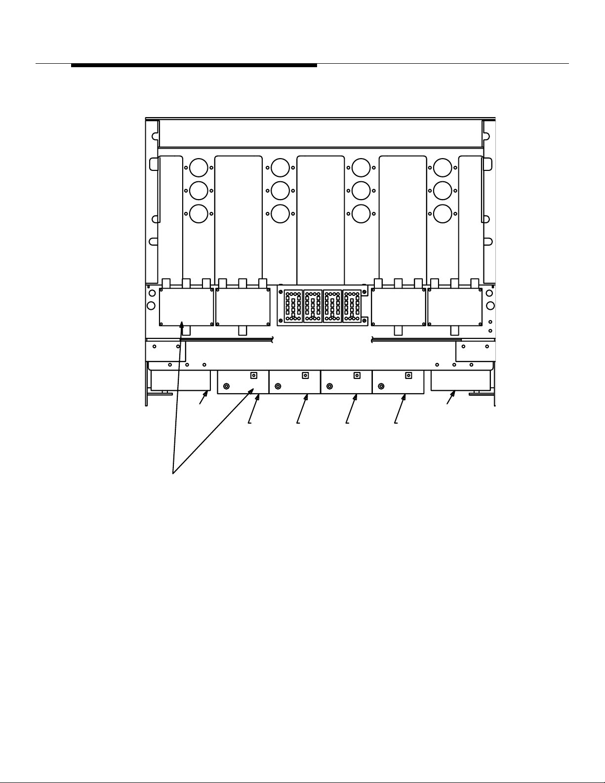
The Frame Interface Assembly (FIA) (see Figure 8-24) contains a bank of filter
capacitors used to filter the DC voltage applied to the Linearizer unit (LZR) and
the Linear Amplifier Unit (LAU). In addition, the FIA combines the Radio
Frequency (RF) inputs from the Radio Channel Frames (RCFs) through a 3:1
power combiner and applies the combined RF output to an attenuator/
preamplifier. The output of this attenuator/pre amplifier is adjus ted as requ ir ed and
applied to the LZR. Also, Linear Amplifier Frame (LAF) alarm status request and
alarms pass through the FIA.
Lucent Technologie s — Propriet ary
See notice on first page
401-660-100 Issue 11 August 2000
8-61
Page 29
Series II Cell Site Equipment Descriptions
.
PD1
(LAC 0)
(LAC 4)
AIR
INLET
C10
C9
C8
PD1
(LAC 2)
(LAC 6)
LAC 0
LAC 4
C20
C19
C18
P4
P2
LAC 3
LAC 1
LAC 5
PA1PA1
LAC 2 LAC 3
LAC 6
P3
LAC 2
LAC 6
PA1
P1
LAC 0
LAC 4
C15
C14
C13
PD1
(LAC 3)
PA1
LAC 1
LAC 5
C5
C4
C3
PD1
(LAC 1)
(LAC 5)
AIR
OUTLET
8-62
/O J41660CA-1
HOWN FOR
EFERENCE ONLY
TOP VIEW
(DOOR, HINGES, CABLE DUCT & BRACKET, CONNECTOR REMOVED)
Figure 8-24. Frame Interface Assembly ED-2R838-30
Lucent Technologie s — Propriet ary
See notice on first page
401-660-100 Issue 11 August 2000
Page 30
Series II Cell Site Equipment Descriptions
P2
LAC 1
LAC 5
C6 C11C16
C7
C8
C9
C10
C17 C2
C18
C19
C20
P4
LAC 3
C12
P3
LAC 2
LAC 6
P1
LAC 0
LAC 4
C1
TB1
C3C13
C4C14
C5C15
BOTTOM VIEW (CABLE DUCT REMOVED)
REAR VIEW
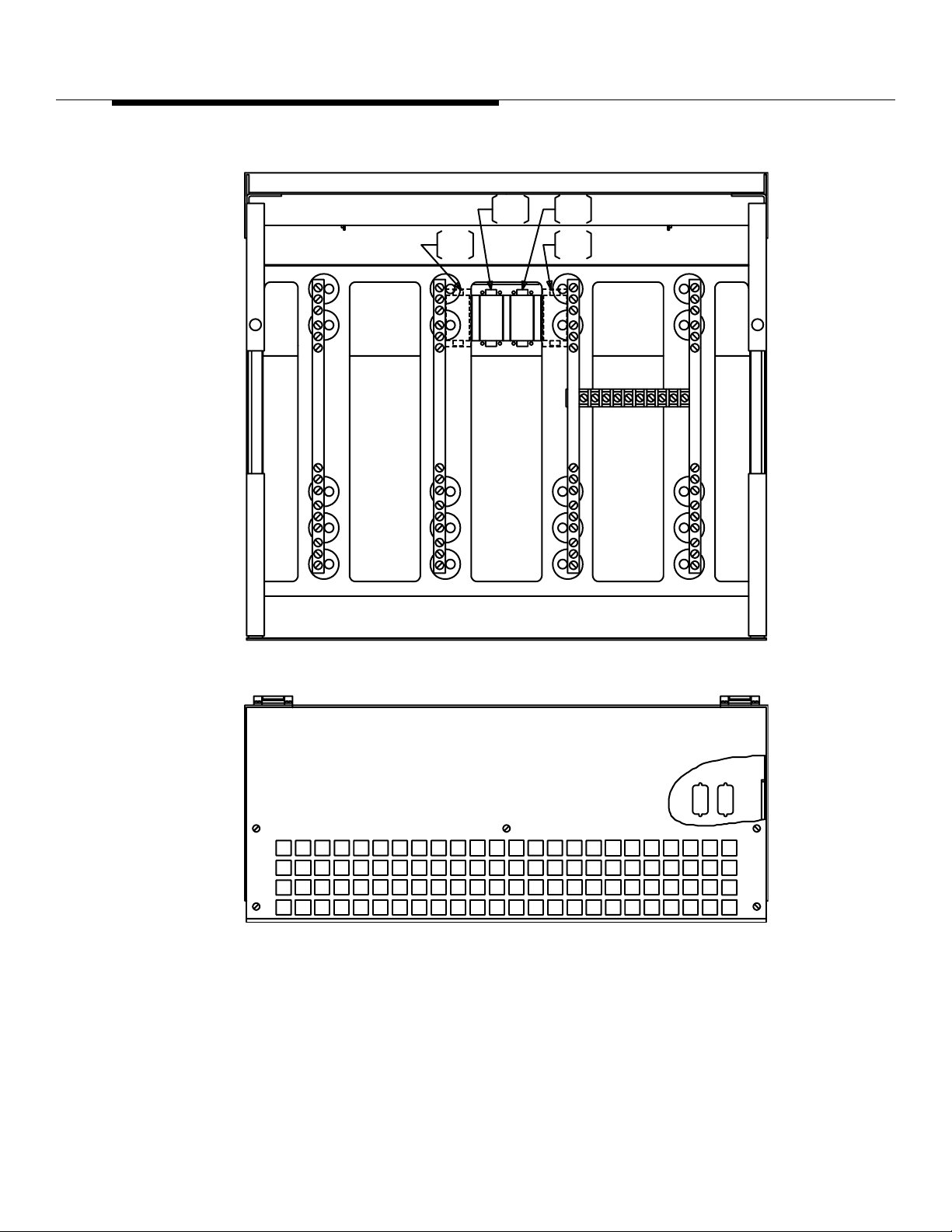
Figure 8-25. Frame Interface Assembly ED-2R838-30
Lucent Technologie s — Propriet ary
See notice on first page
ED2R83B-30
J2J1
401-660-100 Issue 11 August 2000
8-63
Page 31
Series II Cell Site Equipment Descriptions
Series II Cell Site Antenna Interface
Frame (AIF), Overview
The major hardware units on the Antenna Interface Frame (AIF) are listed below
and are described functionally in the following paragraphs.
Receive, Alarm, and Power Distribution Panel
■
Reference Frequency Generator (RFG)
■
Radio Test Unit (RTU) Switch
■
Receiver Calibr ation Generator (RCG)
■
Receive Filter Panel (RFP)
■
Transmit Filter Panel.
■
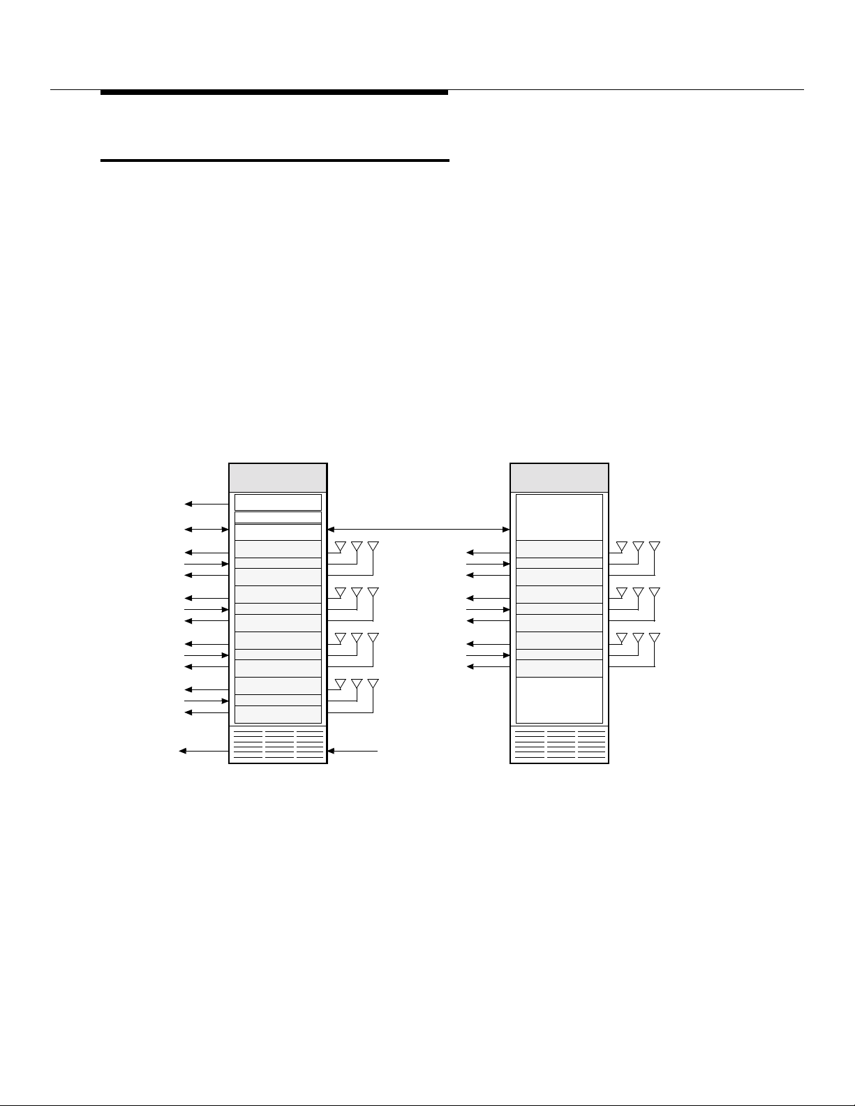
RCF
RTU/
TRTU/
CRTU
RCF
LAC 0
RCF
RCF
LAC 1
RCF
RCF
LAC 2
RCF
RCF
LAC 3
RCF
RCC
15 MHz
ALARMS
PRIMAR Y—AIF0
REF FREQ GEN
RCVR CAL GEN
RTU Switch Panel
RX 0 RX 1TX
RX 0 RX 1TX
RX 0 RX 1TX
RX 0 RX 1TX
ALARMS
ANT 0
ANT 1 ANT 5
ANT 2 ANT 6
ANT 3
FIF
RCF
LAC 4
RCF
RCF
LAC 5
RCF
RCF
LAC 6
RCF
GROWTH—AIF1
RX 0 RX 1TX
RX 0 RX 1TX
RX 0 RX 1TX
Figure 8-26. Antenna Interface Frame (AIF) Functional Diagram
ANT 4
8-64
The Antenna Interface Frame (AIF) has two configurations—a primary frame
(J41660E-2) and a growth frame (J41660F-2). The Antenna Interface Frame
(AIF) provides the interface and signal filtering circuitry required to complete t he
Lucent Technologie s — Propriet ary
See notice on first page
401-660-100 Issue 11 August 2000
Page 32
Series II Cell Site Equipment Descriptions
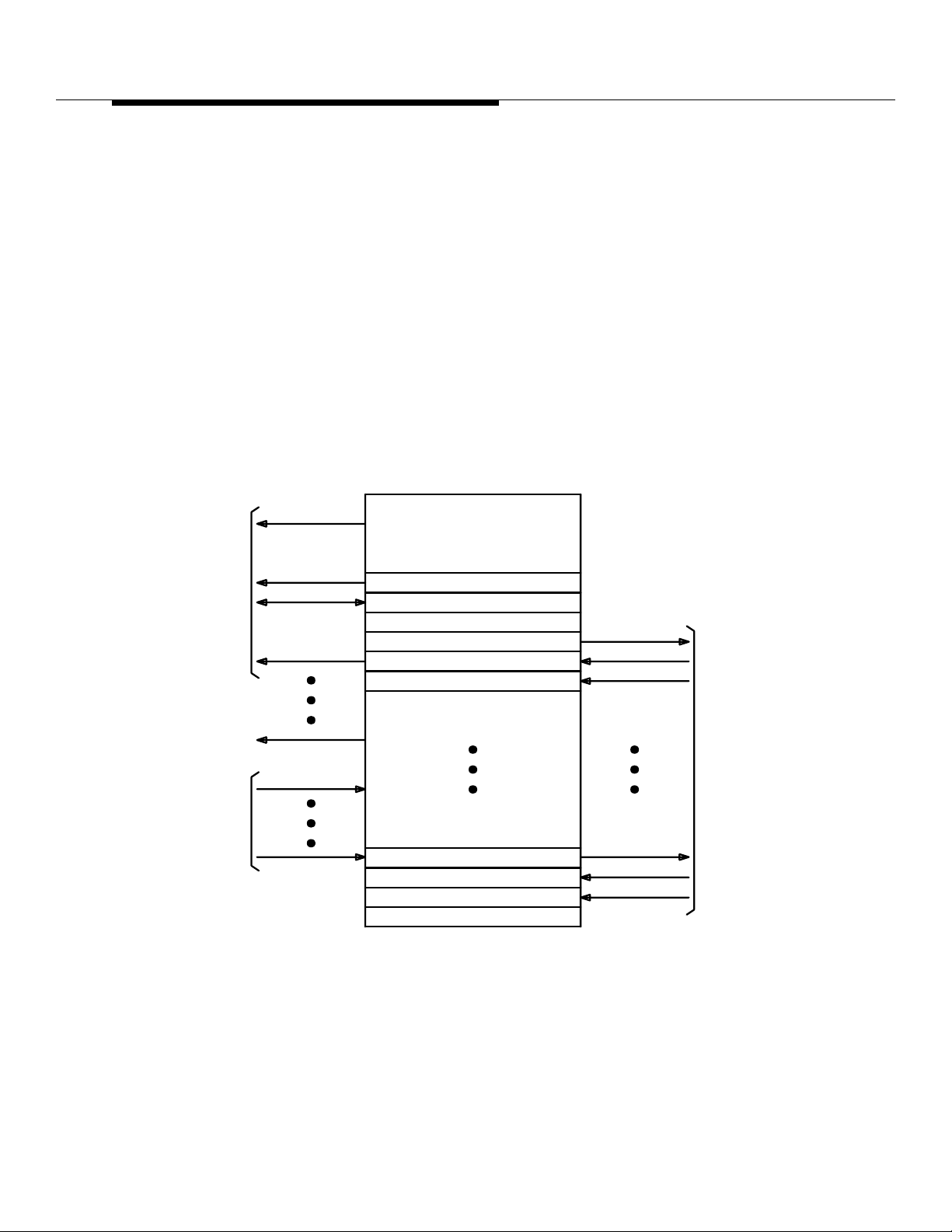
Cell Site Receive (RX) and Transmi t (TX) RF paths from the RX and TX antennas
to the LAFs and Radio Channel Unit (RCUs) inside the RCFs. This is
accomplished through the TX and RX filter panels (TFPs and RFPs) in the AIF.
In addition to the Radio Frequency (RF) filtering and interface circuitry, the AIF
contains the test circuitry required for radio diagnostics. A test switch matrix is
used to establ ish t he requi red tes t paths . A Rec eiv er Calib rati on Gener at or (RCG)
is used to set a known le vel for RX path loss calibration. The AIF also contai ns a
highly accurate Cell Site Reference Frequency Generator.
The major assemblies maki ng up each configuration are liste d and described
below. Note that a duplexer fil ter panel is a v ail ab le t o replace the separ at e receive
and transmit filter panel s. The duplexer filter panel has one configuration f or the
“A” band and another for the “B” band.
ALARMS
POWER/ALARM
TO
RADIO
CHANNEL
FRAME
SET
TO
LINEAR
AMPLIFIER
FRAME(S)
REFERENCE
RF TEST
RECEIVE RF
TRANSMIT RF
REF FREQ GENERATOR
TEST SWITCH MATRIX
CALIBRATION GENERATOR
TRANSMIT FILTER PANEL
RECEIVE FILTER PANEL
RECEIVE FILTER PANEL
COAX
FEEDER
CABLES
TO
ANTENNAS
TRANSMIT FILTER PANEL
RECEIVE FILTER PANEL
RECEIVE FILTER PANEL
Figure 8-27. A ntenna Interface Frame (AIF) Functional Architecture
Lucent Technologie s — Propriet ary
See notice on first page
401-660-100 Issue 11 August 2000
8-65
Page 33
Series II Cell Site Equipment Descriptions
MONITOR
TRANSMIT
RTU RX
TO
RCF0
MONITOR
ANTENNA
FROM
SH 1
RTU TX
FROM
RCF0
POWER AND
CONTROL
FUTURE
APPLICATIONS
RTU
XMTR
TX-ANT
P1
DIV0
DIV1
P2
SWITCH PANEL (RSP)
1:2
RCVR
RX-ANT
RCVR
RX-ANT
J3
J2
J4
J1
3
FROM TFP0 (-50 dB PORT)
OR DFP0 (PD1-J2)
FROM OTHER
TFP’s (-50 dB PORT)
OR DFP’s (PD1-J2)
4
FROM TFP0 (-40 dB PORT)
OR DFP0 (PD2-J2)
7:11:2
1:7
1:7
FROM OTHER
TFP’s (-40 dB PORT)
OR DFP’s (PD2-J2)
5
TO R0FP0 (-50 dB PORT)
OR DFP0 (PD1-J3)
TO OTHER DIV0
RFP’s (-50 dB PORT)
OR DFP’s (PD1-J3)
6
TO R0FP0 (-40 dB PORT)
OR DFP0 (PD2-J3)
TO OTHER DIV0
RFP’s (-40 dB PORT)
OR DFP’S (PD2-J2)
7
TO R1FP0 (-50 dB PORT), SH 3
TO OTHER DIV1
RFP’s (-50 dB PORT)
8
TO R1FP0 (-40 dB PORT), SH 3
TO OTHER DIV1
RFP’s (-40 dB PORT)
TO
SH 3
TO
SH 3
FROM
SH 3
FROM
SH 3
FROM
SH 3
FROM AIF0
R0FP0 OR
DFP0
FROM
SH 3
FROM
AIF0
R1FP0
FROM
OTHER
AIF0
RFP’s
OR
DFP’s
RAP
9
1:6
10
1:6
1:6
1:6
1:6
1:6
1:6
1:6
8-66
RTU-S
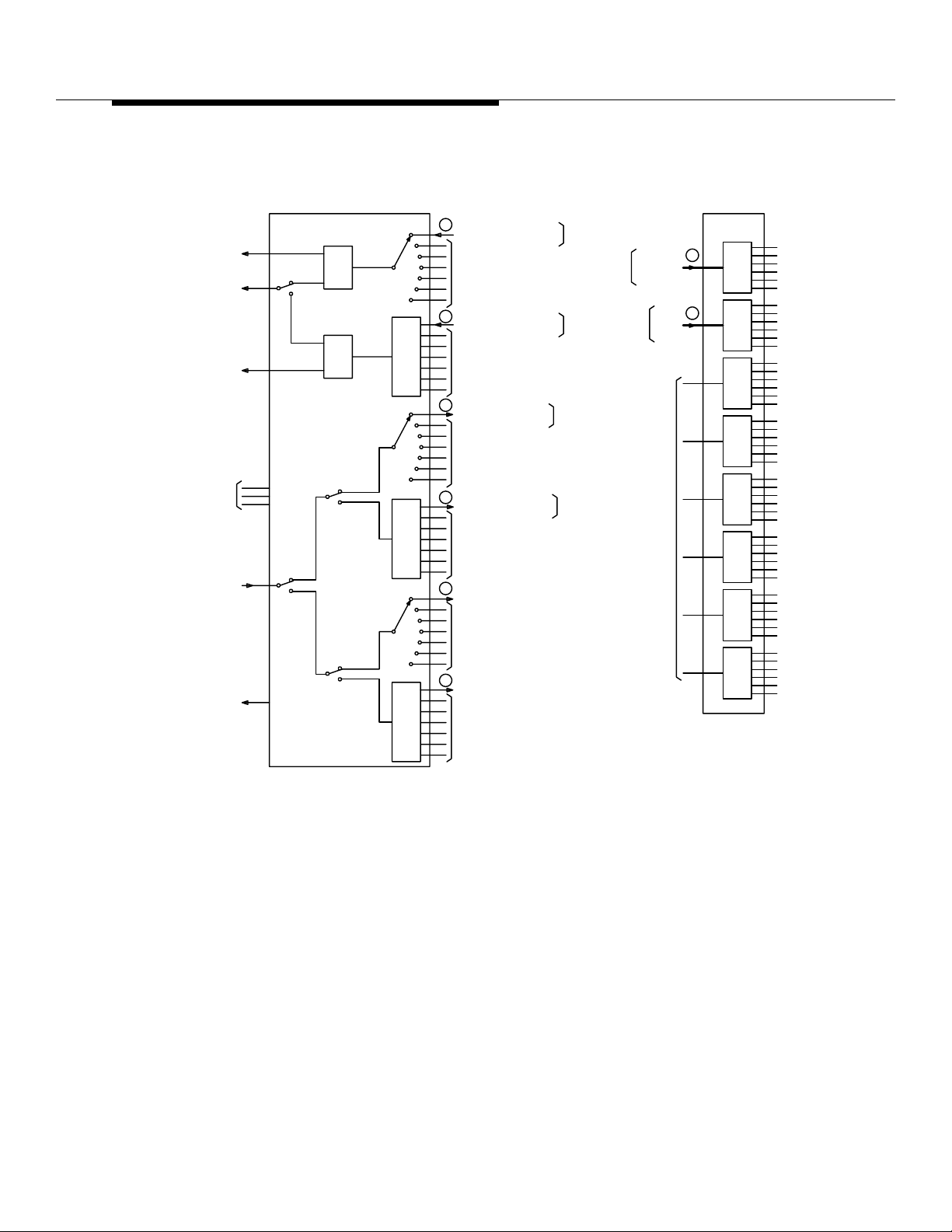
Figure 8-28. Antenna Interface Frame (AIF) Functional Diagram
Lucent Technologie s — Propriet ary
401-660-100 Issue 11 August 2000
RAP
See notice on first page
Page 34
Series II Cell Site Equipment Descriptions
TRANSMIT FILTER PANEL 0
TFP0
4
6
FROM RSP
8
FROM RSP
PD2
1:2
J2
4
TO/FROM RSP
FROM RSP
CP3
-40 dB
TO RSP
(SH 2)
CP1
-40 dB
(SH 2)
CP1
-40 dB
(SH 2)
CP3
J3
(SH 2)
CP1
(SH 2)
-50 dB
3
-50 dB
5
-50 dB
7
-50 dB-40 dB
PD1
1:2
J3J2
536
-50 dB-40 dB
78
TO
TRANSMIT
ANTENNA
FROM
RECEIVE
ANTENNA
FROM
RECEIVE
ANTENNA
TO COMBINED
TRANSMIT/RECEIVE
ANTENNA
FROM
RECEIVE
ANTENNA
J4
J4
J4
J4
J4
(NON-DUPLEXER)
FROM
HY1
FL2
NOTCH
LINEAR AMPLIFIER
CIRCUIT 0
(LAC0)
FL3
BPF
RECEIVE FILTER PANEL, DIV0
R0FP0 (A BAND)
FL1
BPF
RECEIVE FILTER PANEL, DIV1
R1FP0 (B BAND)
FL1
BPF
TYPICAL FILTER PANEL SET
(DUPLEXER)
DUPLEXER FILTER PANEL
DFP0
DUPLEXER
FL1
BPF
RECEIVE FILTER PANEL
R1FP0
FL1
BPF
FL2
NOTCH
CP2
J3
1
FROM RCG
(SH 1)
CP2
J3
2
FROM RCG
(SH 1)
FL3
BPF
CP2
J3
1
FROM RCG
(SH 1)
CP2
J3
2
FROM RCG
(SH 1)
+24V
+24V
+24V
+24V
10
10
50
9
9
TO RAP
(SH 2)
TO RAP
(SH 2)
FROM
LAC0
TO RAP
(SH 2)
TO RAP
(SH 2)
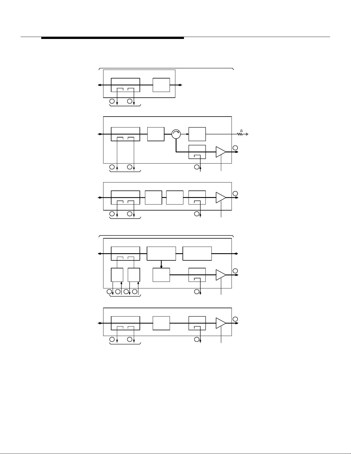
Figure 8-29. Antenna Interface Frame (AIF) Functional Diagram
Lucent Technologie s — Propriet ary
See notice on first page
401-660-100 Issue 11 August 2000
8-67
Page 35
Series II Cell Site Equipment Descriptions
RECEIVE AND POWER
DISTRIBUTION
(RP)
AIF1
24V
EEDERS
ROM
IF0
FROM
AIF1
RFP’s
OR
DFP’s
DIV0 PREAMP POWER
DIV1 PREAMP POWER
1:6
1:6
1:6
1:6
+24V FEEDERS
TO
AIF1 PREAMPS
OUTPUTS
TO
RCF(s)
8-68
1:6
1:6
Figure 8-30. Antenna Interface Growth Frame (AIF) Functional Diagram
Lucent Technologie s — Propriet ary
See notice on first page
401-660-100 Issue 11 August 2000
Page 36

Series II Cell Site Equipment Descriptions
Series II Cell Site
Reference
Frequency
Generator (RFG)
Shelf
The Referen ce Frequency Generator (RFG) provides a 15-MHz precision
reference frequency at a level of +12 dBm ±2 dB. The 15-MHz signal is used as a
reference frequency by the Radio Channel Units (RCUs) and the Radio Test Unit
(RTU) to produce the desired output frequency. The oscillator circuit i s monitored
for and indicates when a fault has occurred. When the RFG shelf supports two
oscillators, only one oscillator is on line at a time as indicated by Light Emitting
Diodes (LEDs).
There are three options a vailable for the RFG shelf, as follo w s:
1. RFG shelf with one (1) Rubidium oscillator.
2. RFG shelf with tw o (2) Rubidium oscillators .
3. RFG shelf with one (1 ) Rubidium oscillator and one (1) crystal oscilla tor.
Series II Cell Site Receiver Calibration Generator ED-2R845-30
This unit generates the Radio Frequency (RF) test signals used in calibrating the
RF path loss within the Cell Site.
The Receiver Calibration Generator (RCG) provides a stable unmodulated
calibration sign al on Mobile Tr ansmit channel 990. The RCG has a total of 16
Radio Frequency (RF) ports (only 14 are used). These ports are coupled to the
inputs of the preamplifiers i n the receive paths insid e the AIF through 20-dB
directional coupler s. The calibration signal is used by each Radio Channel Unit
(RCU to determine a correction factor required for its Received Signal Strength
Indicator (RSSI) out put. The correction f actor is used to compensate for non
frequency dependent losses in each RCU receive path.
The stability of the RCG output frequency is the same as that of the 15-MHz
reference frequency. The RCG output frequency is factory preset to channel
990—824.01 MHz. The nominal outp ut po wer level of each of the 16 RCG ports is
-58 dBm ±1.5 dB.
There are four translations entries which affect Receiver Calibration.
Freque ncy (Found in the Cell Form)
■
Tolerance (Also found in the Cell Form)
■
Receive Signal Strength Calibration Diversity 0 (Referred to as the
■
Expected Value, found in the CEQFACE form)
Receive Signal Strength Diversity 1 (Referred to as the Expected Value,
■
also found in the CEQFACE form).
The RCUs must be reset before these parameters will have an effect. The
Receive Signal Strength Calibr ation para meters f or div ersity 0 and 1 apply to each
face . Changing either of these parameters will only affect the RCUs on that face.
Lucent Technologie s — Propriet ary
See notice on first page
401-660-100 Issue 11 August 2000
8-69
Page 37

Series II Cell Site Equipment Descriptions
During an RCU restore sequence, the data decoder tunes to the calibration
channel (990) and makes signal strength measurements for each antenna
diversit y. As a result of these measurement s, one of the following three things
happens:
If the measurement fal ls within the tolerance value but is not e xactly the
■
same as the expected value, the decoder records the di fference between
the expected value and the actual measurement. Subsequent
measurements made by that radi o are adjusted by this value.
If any of the measurements f all outside of tolerance, no corrections are
■
made to the measured signal strengths. Also, a Receiver Calibration HEH
Error message is printed out on the receive-only printer (ROP).
If the measured value is the same as the expected val ue, no adjustments
■
are made.
Receiver cal ibra tion err ors can be the result of incorr ect tr anslat ions , def ec tiv e RF
cabling, faulty RCUs, defective preamps , or basically any problem found between
the RCG and the RCUs.
There are two AIF models—AIF0 (primary) and AIF1 (growth). AIF0 cont ains a
Receive, Alarm, and Power Dis tribution Panel (RAP), an RFG, an RCG, and a
Radio Test Unit Switch P anel (RSP). AIF0 can be equipped wit h one to f our sets of
filter panels (a singl e set consists of one TX and two RX filter panels unless it is
duplexed).
AIF1 Frame 0
AIF1 serves as an auxiliary frame to accommodate additional filter panels. It
contains a Receiv e and Power (RP) Distribution Panel and can be equipped with
one to three additional filter panel sets.
Integrated Duplexer Filter Panels (DFPs ) are opt ional. When equipped, a DFP
assembly can be used to combine a TX filter panel with an RX filter panel and
share one combined RX/TX antenna port, thus reducing the required number of
antennas from three to two per antenna face. Unless otherwise specified, a DFP
combines the RX DIV0 path with the TX path.
AIF0 combined with AIF1 accommodates up to seven antenna faces, typically
consisting of seven TX paths and 14 RX pa ths. Each an tenna f a ce r equire s an RX
filter for the diversity 0 (DIV0) RX path, a TX filter for the TX path, and an RX filter
for the diversity 1 (DIV1) RX path.
There are some interframe connections between AIF0 and AIF1 to provide the
follo w ing circuit functions. The RSP in AIF0 switches test signals from the RTU
(located in the P-RCF) to and from various RX and TX paths of both AIF0 and
AIF1 for system diagnostics. The RAP panel in AIF0 connects the +24 volt DC
power supplies to all of the preamplifiers inside the Receiver Filter Panels (RFPs)
8-70
Lucent Technologie s — Propriet ary
See notice on first page
401-660-100 Issue 11 August 2000
Page 38

Series II Cell Site Equipment Descriptions
or DFP(s) of both AIF0 and AIF1. The RCG in AIF0 provides a leveled signal to
calibrate all of the RX paths from the AIF equipment all the way to the inputs of the
RCUs. There are RF connections from AIF0 to the RCF(s), the LAF(s), the RX
antennas and the TX antennas.
Lucent Technologie s — Propriet ary
See notice on first page
401-660-100 Issue 11 August 2000
8-71
Page 39
Series II Cell Site Equipment Descriptions
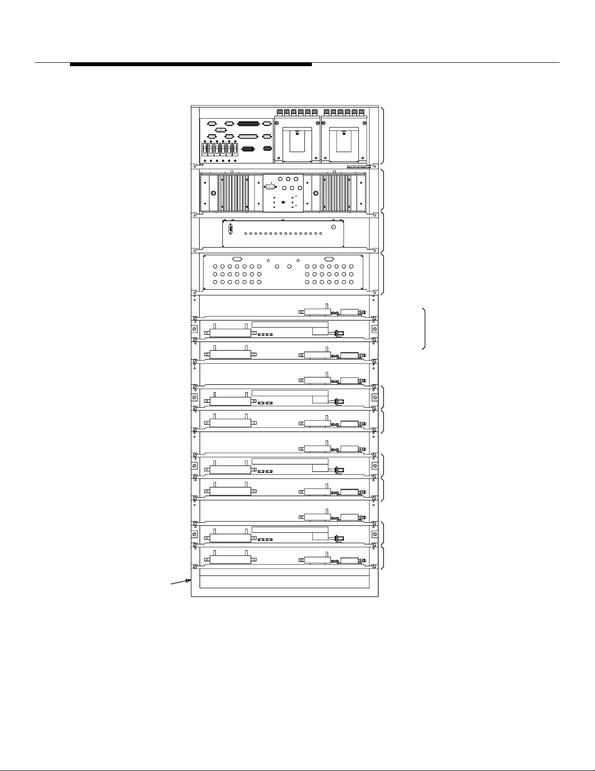
RECEIVE, ALARM & POWER
DISTRIBUTION PANEL
REFERENCE FREQUENCY
GENERATOR
RECEIVER CALIBRATION
GENERATOR
RADIO TEST UNIT
SWITCH
D-2R820-30
ABINET
PRIMARY FRAME - WITH DUPLEXER FILTER PANEL
RECEIVE
SECTION
TRANSMIT
SECTION
RECEIVE FILTER PANEL
DUPLEXER FILTER
PANEL
RECEIVE FILTER
PANEL
DUPLEXER FILTER
PANEL
RECEIVE FILTER
PANEL
DUPLEXER FILTER
PANEL
RECEIVE FILTER
PANEL
DUPLEXER
FILTER
PANEL
8-72
Figure 8-31. Primary Antenna Interface Frame (AIF) J41660E-2
Lucent Technologie s — Propriet ary
See notice on first page
401-660-100 Issue 11 August 2000
Page 40
Series II Cell Site Equipment Descriptions
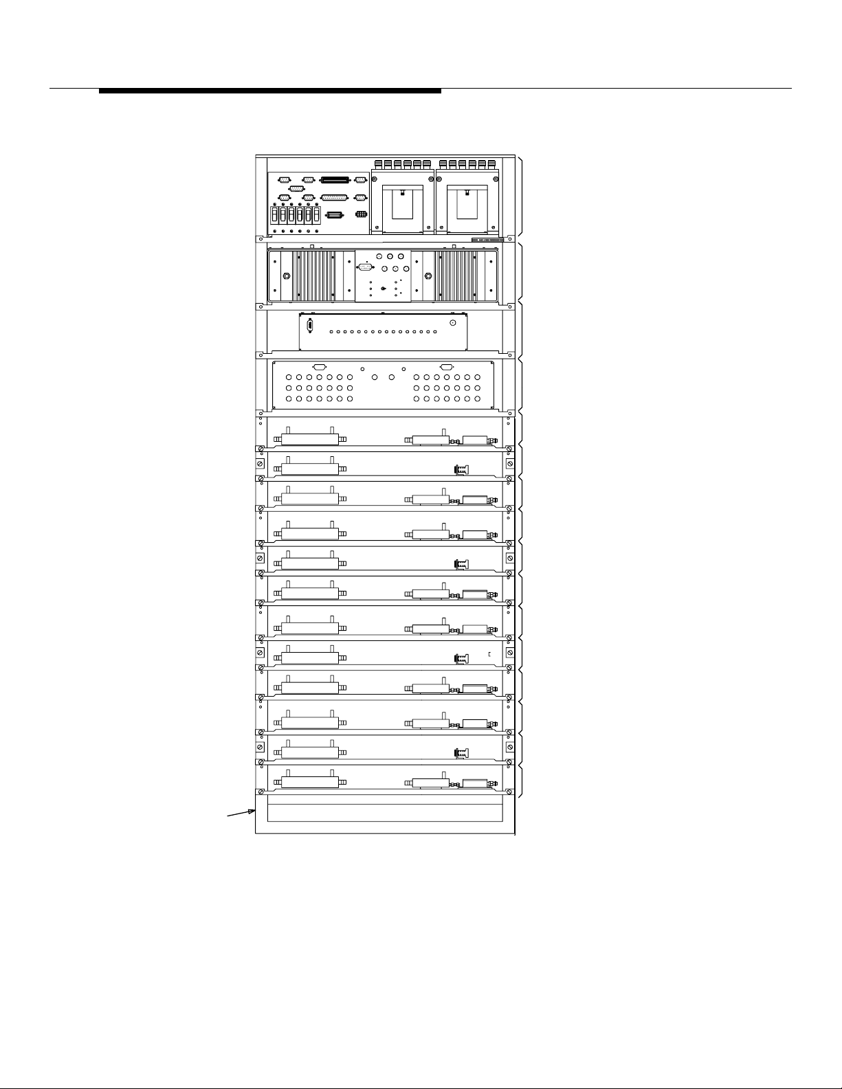
RECEIVE, ALARM & POWER
DISTRIBUTION PANEL
REFERENCE FREQUENCY
GENERATOR
RECEIVER CALIBRATION
GENERATOR
RADIO TEST UNIT
SWITCH
RECEIVE FILTER
PANEL
TRANSMIT FILTER
PANEL
RECEIVE FILTER
PANEL
RECEIVE FILTER
PANEL
TRANSMIT FILTER
PANEL
RECEIVE FILTER
PANEL
RECEIVE FILTER
PANEL
TRANSMIT FILTER
PANEL
RECEIVE FILTER
PANEL
RECEIVE FILTER
PANEL
TRANSMIT FILTER
PANEL
RECEIVE FILTER
PANEL
D-2R820-30
ABINET
PRIMARY FRAME - WITHOUT DUPLEXER FILTER PANEL
Figure 8-32. Primary Antenna Interface Frame J41660E-2
Lucent Technologie s — Propriet ary
See notice on first page
401-660-100 Issue 11 August 2000
8-73
Page 41
Series II Cell Site Equipment Descriptions
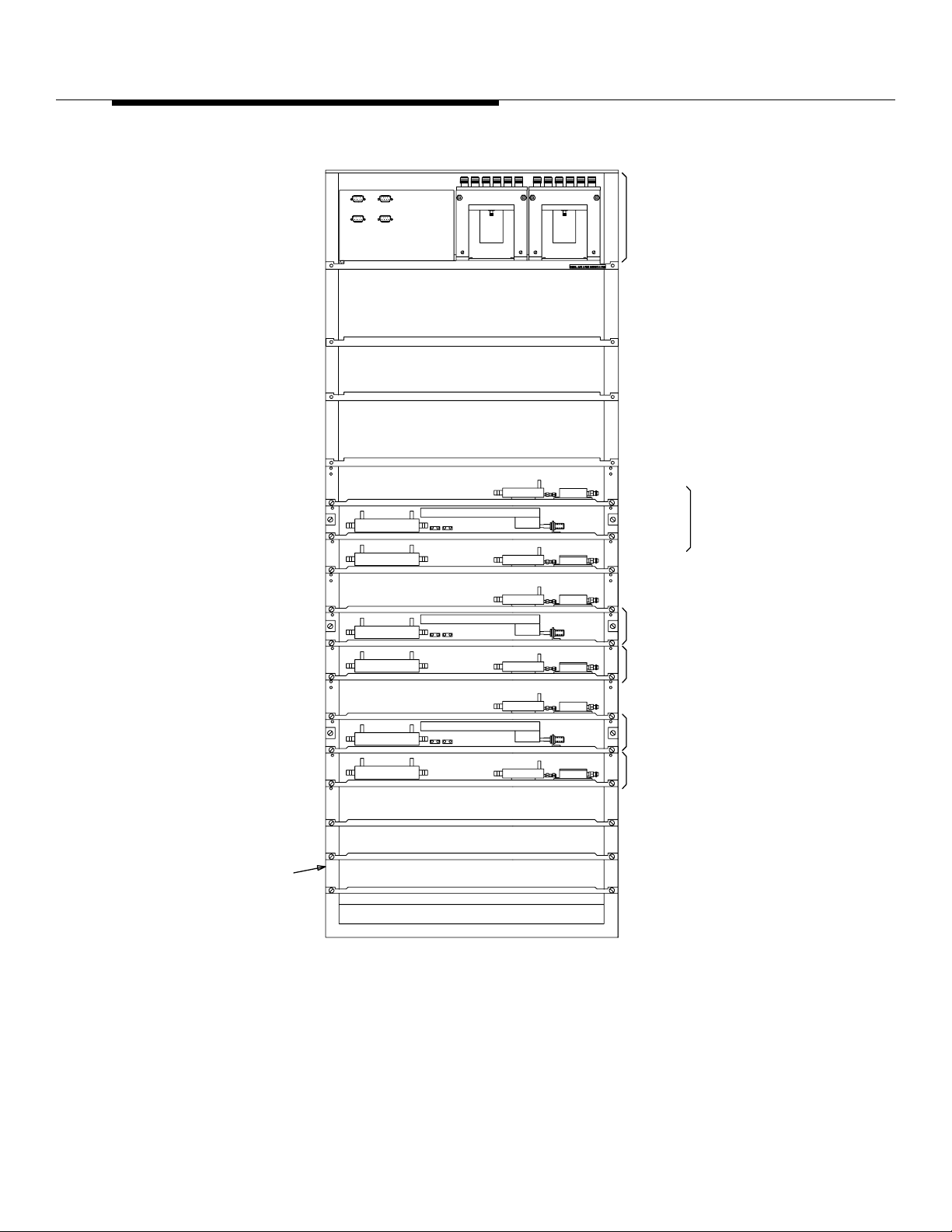
POWER AND
DISTRIBUTION PANEL
D-2R820-30
ABINET
RECEIVE
SECTION
TRANSMIT
SECTION
RECEIVE FILTER PANEL
DUPLEXER FILTER
PANEL
RECEIVE FILTER
PANEL
DUPLEXER FILTER
PANEL
RECEIVE FILTER
PANEL
DUPLEXER
FILTER
PANEL
8-74
SECONDARY FRAME-WITH DUPLEXER FILTER PANEL
Figure 8-33. G rowth Antenna Interface Frame J41660F -2
Lucent Technologie s — Propriet ary
See notice on first page
401-660-100 Issue 11 August 2000
Page 42
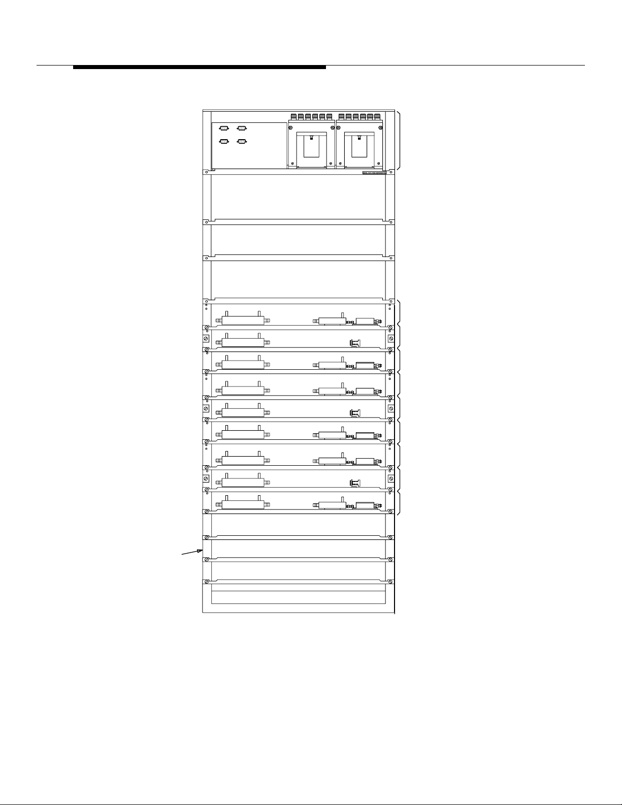
Series II Cell Site Equipment Descriptions
RECEIVE AND POWER
DISTRIBUTION PANEL
RECEIVE FILTER
PANEL
TRANSMIT FILTER
PANEL
RECEIVE FILTER
PANEL
RECEIVE FILTER
PANEL
TRANSMIT FILTER
PANEL
RECEIVE FILTER
PANEL
RECEIVE FILTER
PANEL
TRANSMIT FILTER
PANEL
RECEIVE FILTER
PANEL
ED-2R820-30
CABINET
SECONDARY FRAME-WITHOUT DUPLEXER FILTER PANEL
Figure 8-34. G rowth Antenna Interface Frame J41660F-2
Lucent Technologie s — Propriet ary
See notice on first page
401-660-100 Issue 11 August 2000
8-75
Page 43

Series II Cell Site Equipment Descriptions
Series II Cell Site
Radio Switch
Panel
Series II Cell Site Radio Test Unit (RTU) Switch Panel
This switc h panel establishes the functional Radio Frequency (RF) tes t pat h used
by the Radio Test Unit (RTU) during diagnostic testing. These paths include the
following:
Receiver-Forward Signal Injection
■
Receiver-Reflected Signal Injection
■
Transmit-Forward Signal Measurement
■
Transmit-Reflected Signal Measurement.
■
The test paths are made through directional couplers containing forward and
reflected ports. Under software control, the R TU switch estab lishes the required
paths to test all major functional operations.
The Radio Switch Panel (RSP) provides the RTU (located in RCF0) access to the
Cell Site Rx and Tx (Receive and Transmit) paths through a test matrix Radio
Fr equency (RF) distribution network. The RTU is coupled to the incident and
reflected path of every antenna used by the Cell Site through the RSP. RF test
signals to and from the RTU test receiver and the transmitt er are con nect ed to the
RSP. The RSP receives logic control signals from the RTU to switc h the RF test
signals from the RTU to the Rx and Tx paths under test.
The RTU is used primarily to verify the Rx and Tx paths to and from the transmit
and receive antennas of the Cell Site. The RTU contains a test receiver and test
generator which serv e to simulat e a subscri ber unit . The test receiv er and the te st
generator can be tuned to an y channel. Tuning is accomplished with commands
sent over the TDM bus to an Rx/Tx frequency synthesizer within the RTU. The
RTU controls t he RF s witches located in the RSP. The TDM bus is always inst alled
"red stripe up."
Series II Cell Site
Receiv e, Alarm,
and Power
Distribution Panel
ED 2R851-30
8-76
401-660-100 Issue 11 August 2000
During Rx testing on a Cell Site Radio Channel Unit (RCU), the test generator
within the RTU is tuned to the channel under test, and the output of the test
generator is applied to the appropriate Cell Site receiving antenna. Control is
applied to the RSP in AIF0 to select Omni Rx or one face of the directional
antenna. RCU transmitter te sti ng is accomplished by connecting the test receiver
to the appropriate Tx path and tuning the RTU to the channel under test.
This panel provides an inte rface between the primary Antenna Interface Frame,
AIF0, and other Cell Site equipment for distributing the receive signals, the alarm
and control signals, and the +24-volt DC power. The +24-volt DC for the growth
AIF1 is supplied from this panel.
The Receive, Alarm, and Power (RAP) distribution panel contains the circuit
breakers that f eed +24 v olts to unit s on the primary Antenna Interface F r ame (AIF)
and to the gro wth frame . This panel also contai ns power dividers used to dist ribute
Lucent Technologie s — Propriet ary
See notice on first page
Page 44

Series II Cell Site Equipment Descriptions
received Radi o Frequency (RF) to the Radio Channel Frame (RCF) and alarm tiepoints for customer alarms. These alarms are fed bac k to the Alarm/FITS (F actory
Installation Test Set) board located on the P-RCF.
The +24 volt DC power from the power plant is applied as FDR0 through CB1 to
the RFG, through CB4 to the Receiv er Calibration Generator (RCG), and through
CB5 to all of the preamplifiers inside t he DIV0 Rx filt er panels of both AIF0 and
AIF1. FDR1 is applied through CB2 to the RFG, through CB3 to the RSP, and
through CB6 to the DIV1 Rx filter panels in both AIF0 and AIF1.
The RAP panel provi des user alarm connections and alarm signal s from the AIFs
to the RCF0 alarm circuits. It also provides interface connecti ons between the
RTU (inside RCF0) and the RSP (inside AIF0). The antenna select output of the
RTU sends logic sign als to command the RSP to switch the Radio Frequency
(RF) test signals from the R TU to various Rx and Tx (Receive and Transmit)
antenna paths under test. The antenna message acknowledge output of the RSP
acknowledges the RTU upon successful execution of its commands.
Series II Cell Site
Receiv e and Power
Distribution Panel
ED-2R853-31
Series II Cell Site
Duplexer Filter
Panel
ED-2R848-31
This panel is located in the gro w th Ant enna Int erface Frame, AIF1, and provides
an interface between AIF1 and other Cell Site equipment for distributing the
receive signals and the +24-volt DC received from AIF0.
The outputs of the preamplifiers in the RFPs or DFPs are connected to the
respectiv e 1:6 power dividers mounted ins ide t he RAP. The amplified Rx signals
are distributed to the RCF(s). All of the unused ports on the 1:6 dividers must be
terminated into a 50-ohm resistive load.
The Receive and Power (RP) distribution panel distrib ut es the Rx sign als and +24
volt DC within AIF1. The outputs of the pre ampli fi ers in the RFPs or DFP(s) are
connected to the 1:6 power dividers mounted inside the RP panel. The amplified
Rx signals are distribut ed to t he RCF(s) from thes e power dividers.
This filter panel is a combination rec eive and transmit filter panel with a single Rx/
Tx (Receive/Transmit) antenna port. Two configurations of this filter panel are
used—one f or “A” ban d and one for “B” band. The group number d esignat es the A
or B configuration.
One duplexer filter panel is requi red for each antenna face and one receive filter
panel is required for diversity.
The Duplexer Filter Panel (DFP) is a combined receive and transmit filter panel.
Functionally, the receive and transmit circuits are the same as the separate
receive and transmit filter panels, except that it provides a combined Rx/TS
(Receive/Transmit) antenna port. This allows the Cell Site to use one less
antenna. A separate list number is used to designate use with bands A and B.
Lucent Technologie s — Propriet ary
See notice on first page
401-660-100 Issue 11 August 2000
8-77
Page 45

Series II Cell Site Equipment Descriptions
The Duplexer Filter Panel (DFP) combines a Tx filter panel with an Rx filter panel
and has a single Rx/Tx (Receive/T r ansmit ) antenna po rt. A duplexing technique is
applied, enabl ing the system to use a combined Rx/Tx antenna configuration that
reduces the requir ed number of antennas in each antenna face from three to two.
The duplexer steers the Rx signals from the combined Tx/Rx antenna to t he input
of the BPF in the Rx path and directs the Tx signals f rom the output of the Tx filter
to the Tx/Rx combined antenna port. Unless otherwise specified, the duplexer is
normally used to combine the DIV0 Rx path with the Tx path.
The connections to the DFP are similar to those of t he TFP and RFP, except there
is only one antenna port for the combined Tx/Rx antenna function. There is only
one dual-port directional coupler ( -50 dB and -40 dB) requ ired i n the DFP. Two 2:1
combiners are used to provi de connections to the R TU for radio test diagnostics.
The calibration signa l from the Recei ver Calibration Generator (RCG) is coupled
into the Rx path through a 20-dB directiona l coupl er similar to that of the RFP.
Series II Cell Site
Receive Filter
Panel
ED-2R846-31
This filter panel contains a bandpass and a notch filter , a low-noise receive
preamplifier and two couplers used to inject fo rward and reflected Ra dio
Frequency (RF) test signals. These test signals are used to test the receive path
for the Radio Channel Units (RCUs). One filter panel is required for each receive
path inside the Antenna Interface Frame (AIF) unless a Duplex Filter Panel is
used.
The Receive Filter Panel (RFP) receives the Radio Frequency (RF) from the
receive ant ennas. The RF is first pass ed through a coupler wher e test signals ma y
be injected (forward and reflected). The RF is then passed through a bandpass
filter and a notch filter. A second coupler, after the filters, provides an injection
point for the Radio Channe l Unit (RCU) calibration frequency. The receive RF is
then applied through a preamplifier to power dividers fo r distribution into the RCF.
The RFP works on both A and B bands.
One Receive Filter Panel (RFP) is required for each receive path inside the AIF
unless a Duplexer Filter Panel is used. Typically, each antenna face has two Rx
(Receive) paths for diversity 0 and diver sity 1. The RFP contains a dual-port (-40
dB and -50 dB) directional coupler, a Band Pass Filter (BPF), a notch filter, a 20dB directional coupler, and a 44-dB preamplifier .
The received Radio Frequency (RF) signal from the Rx antenna is sent through
the dual-port directional coupler to the input of the BPF. The -40 dB and -50 dB
coupling ports of this coupler pr ovi de the RTU access to the Rx path of the AIF fo r
test purposes. The R TU s ends and rec eiv es t est si gna ls t hrough t he RSP to t hese
ports in order to test the Rx path for each Radio Channel Unit (RCU) installed in
the RCF(s). Received RF signal s from the Rx antenna are filtered and amplified
by the RFP before entering the RCU. The BPF (which is different for “A” and “B”
band customers) provides the required Rx path filtering characteristics. The
output of the BPF is followed by a notch filter.
8-78
Lucent Technologie s — Propriet ary
See notice on first page
401-660-100 Issue 11 August 2000
Page 46

Series II Cell Site Equipment Descriptions
The calibration signa l from the Recei ver Calibration Generator (RCG) is coupled
into the Rx path through the 20-dB directional coupler at the output of the receive
filters. The cal ibr at ion sig nal pro vides a means to det ermine a correct ion f a ctor for
offsetting the difference in the loss tolerances in the different Rx paths of the
system.
The receive and calibration signals are amplified by the preamplifier inside the
RFP and sent to the RAP in AIF0 or the RP in AIF1.
A typical AIF0 with four antenna faces has a total of eight RFPs and eight 1:6
power dividers at the RAP, namely Face0 Rx0, Face0 Rx1, Face1 Rx0, Face1
Rx1, Fac e2 Rx0, Face2 Rx1, Face3 Rx0, and F ace3 Rx1. A typi cal AIF1 with thr ee
antenna faces has a tot al of six RFPs and six 1:6 pow er divider s at the RP, namely
F ace4 Rx0, F ace4 Rx1, F ace5 Rx0, F ace5 Rx1, F ac e6 Rx0, and F ace6 Rx1. Each
RCF has at least one Rx path connection to one of the six ports of each 1:6
divider. This arrangement enables each RCF to have total access to all of the Rx
paths in AIF0 and AIF1. A maximum of six RCFs can be connected to each Rx
path to the 1:6 power dividers.
Series II Cell Site
Transmit Filter
Panel ED-2R847-31
This filter panel contains a tr ansmit filter and a coupler for picking off a portion of
the forward and reflected pow er. These signals are used during Radio Frequency
(RF) diagnostic test.
The Transmit Filter Panel (TFP) receives transmitted Radio Fr equency (RF) from
the LAF and passes it through a transmit filt er assembly. The transmitted RF is
then fed through a coupler to the transmit antenna. The coupler provides ports for
picking off a portion of the for ward and reflected RF.
One Transmit Filter Panel (TFP) is required for each antenna face. The TFP
contains a dual-port (-40 dB and -50 dB) directional coupler and a band pass
transmit filter. Tx (Transmit) signals from the Radio Channel Unit (RCU) are
amplified by the LAF before reaching the AIF. The Tx signals from the LAF are
filtered b y the Tx filter inside the TFP before being transmitted out by the Tx
antenna. The filtered Tx signal is then sent through the dual-port coupler before
going to the Tx antenna. The -40 dB and -50 dB coupling ports of this coupler
provide the RTU access to the Tx path of the system for test purposes. The RTU
receives tes t signals through the RSP to these ports in order to test the Tx path f or
each RCU installed in the RCF(s). The Tx filter separates out the unwanted
signals bef ore transmitting to the Tx antenna.
Lucent Technologie s — Propriet ary
See notice on first page
401-660-100 Issue 11 August 2000
8-79
Page 47
Series II Cell Site Equipment Descriptions
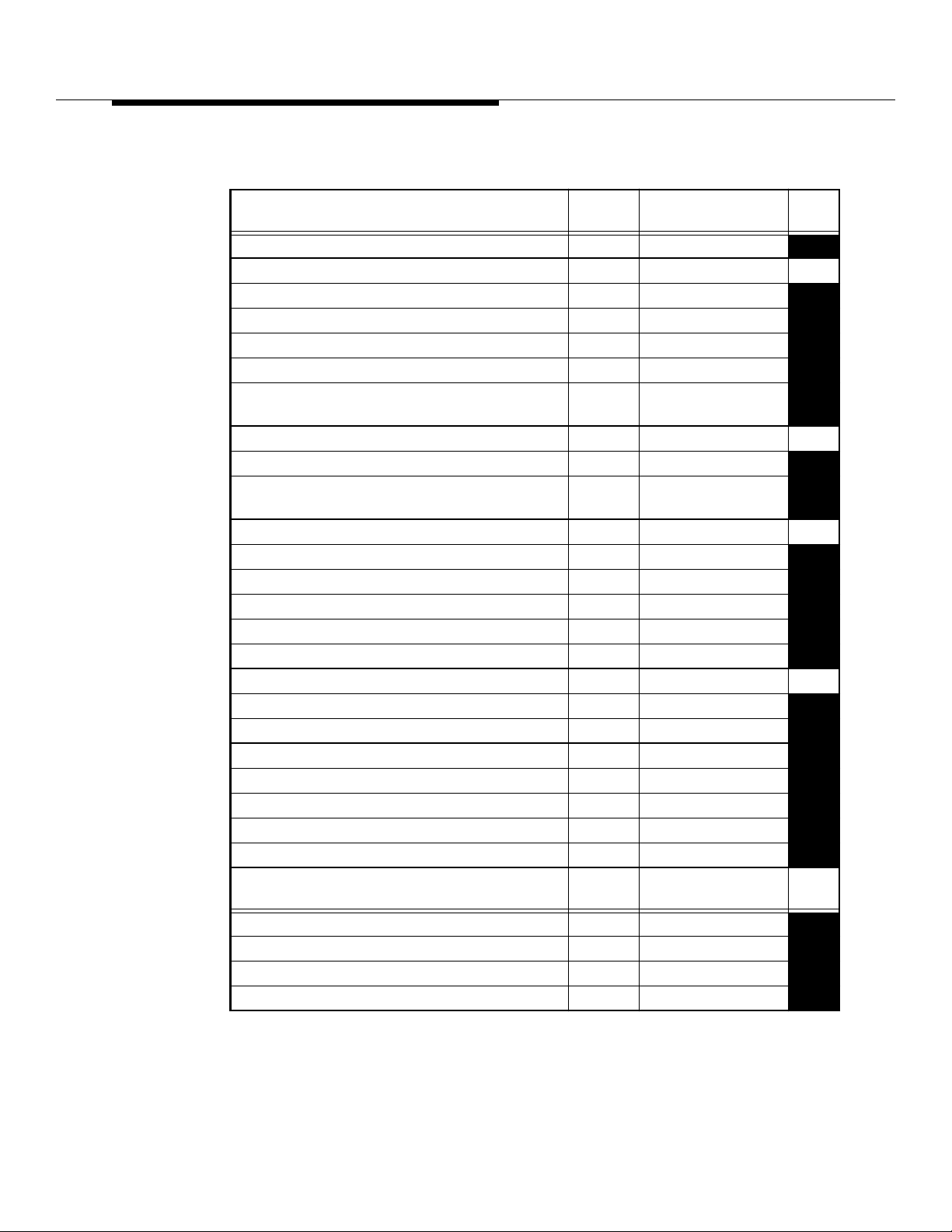
Table 8-14. Antenna Interface Frame (AIF) Hardware
Max
Item
Qty Code
Antenna Interface Frame 0 1 J41660E-2
Eqpt
Loc
Receive, Alarm, and Power Distribution Panel 1 ED-2R851-30 23
Circuit Breakers (CB1, CB2, CB3, CB4) 3A 4 406026401
Circuit Breakers (CB5, CB6) 2.5A 2 406085092
Terminal Strip (TB5, TB6) 2 406131862
Splitter Mounting Kit 2 846441368
Power Div id e r (1:6) 4
KS21604,L12
(per kit)
RFG shelf with one (1) Rubidium oscillator 407575638 22
RFG shelf with two (2) Rubidium oscillat ors 407575653
Provides an RFG shelf with one (1) Rubidium
407575646
oscillator and one (1) crystal oscilla tor
Receiver Calibration Generator 1 ED -2R845-30 21
Power Divider 1 WP92070,L2
Signal Generator Circuit Pack 1 ARL3
Attenuator (AT1, AT3) 2 402910467
Attenuator (AT2) 1 402910442
Termination 2 461-1 (meca)
RTU Switch Panel 1 ED -2R850-30 20
TCI Circuit Pack 1 BBC1
RCV Circuit Packs 2 BBC2
Receive Filter Panel (“A” Band) ED-2R846-31
Coupler (CP1) 40/50 dB 1 KS21603,L8
Coupler (CP2) 20 dB 1 KS21603,L7
Bandpass Receive Filter (FL1) 1 ED-2R815-30
Notch Receive Filter (FL2) 1 ED-2R816-30
Max
Item
Qty Code
Circulator (HY1) 1 WP92072,L2
Preamp (PA1) 1 KS21583,L3
Adapter 1 406083055
Termination 1 401-1 (meca)
Eqpt
Loc
8-80
Lucent Technologie s — Propriet ary
See notice on first page
401-660-100 Issue 11 August 2000
Page 48
Series II Cell Site Equipment Descriptions
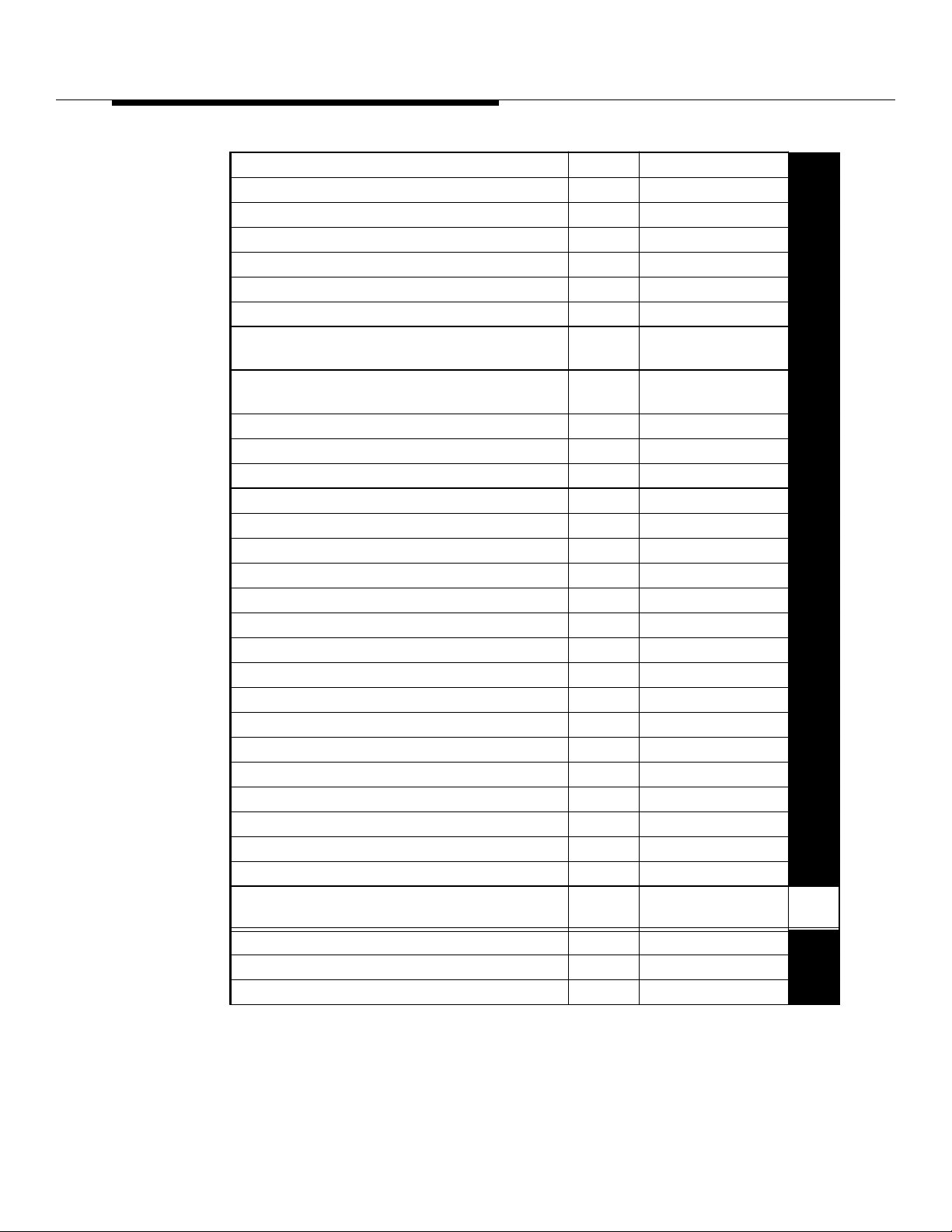
Table 8-14. Antenna Interface Frame (AIF) Hardware (Contd)
Receive Filter Panel (“B” Band) ED-2R846-31
Coupler (CP1) 40/50 dB 1 KS21603,L8
Coupler (CP2) 20 dB 1 KS21603,L7
Bandpass Receive Filter (FL1) 1 ED-2R810-30
Notch Receive Filter (FL2) 1 WP92064,L1
Preamp (PA1) 1 KS21583,L3
Adapter 1 406083055
Transmit Filter Panel (“A” Band; Installer
ED-2R847-31
Mounted)
Transmit Filter Panel (“B” Band; Installer
ED-2R847-31
Mounted)
Coupler (CP3) 1 KS21603,L8
Bandpass Filter (“A” Band) 1 ED-2R860-30
Bandpass Filter (“B” Band) 1 ED-2R860-30
Duplex Filter Panel (“A” Band) ED-2R848-30
Coupler (CP2) 1 KS21603,L7
Coupler (CP3) 40/50 dB 1 KS21603,L8
Power Divider/Combiner (PD1, PD2) 2 KS21604,L1
Bandpass Receive Filter (FL1) 1 ED-2R815-30
Notch Receive Filter (FL2) 1 ED-2R816-30
Bandpass Transmit Filter (FL3) 1 ED-2R860-30
Preamp (PA1) 1 KS21583,L3
Circulator (HY1) 1 WP92072,L2
Adapter (ADPTR 1) 1 406083055
Termination (TRM1) 1 401-1 (meca)
Duplexer Cable Assembly (DPX1) 1 ED-2R875-30
Duplex Filter Panel (“B” Band) ED-2R848-30
Coupler (CP2) 1 KS21603,L7
Coupler (CP3) 40/50 dB 1 KS21603,L8
Power Divider/Combiner (PD1, PD2) 2 KS21604,L1
Max
Item
Qty Code
Bandpass Receive Filter (FL1) 1 ED-2R810-30
Notch Receive Filter (FL2) 1 WP92064,L1
Bandpass Transmit Filter (FL3) 1 ED-2R860-30
Eqpt
Loc
Lucent Technologie s — Propriet ary
See notice on first page
401-660-100 Issue 11 August 2000
8-81
Page 49

Series II Cell Site Equipment Descriptions
Table 8-14. Antenna Interface Frame (AIF) Hardware (Contd)
Preamp (PA1) 1 KS21583,L3
Adapter 1 406083055
Duplexer Cable Assembly 1 ED-2R875-30
* Two terminations are required for a full configuration.
Any other configuration requires more than two terminations.
Special Filters 0
Outside filters, KS-24020, L3 that were designed and required for the Korean
Mobile Telephone (KMT) appli cation can be us ed as pa rt of the Standard Series I I
Cell Site AIF0 and AIF1. If KS-24020, L3 is used, then KS-24174, L1 and KS24022, L2 are not needed.
Transmit notch filters KS24234, L1 to L10, which wer e developed for the Air-toGround Telephone (AGT) appl ication, can also be used as part of the Standard
Series II Cell Site. These are mounted on a standard 19-inch bay frame external
to the AIF and should be grounded appropriately.
8-82
Lucent Technologie s — Propriet ary
See notice on first page
401-660-100 Issue 11 August 2000
Page 50
Series II Cell Site Equipment Descriptions
Series II Cell Site Equipment
Summary
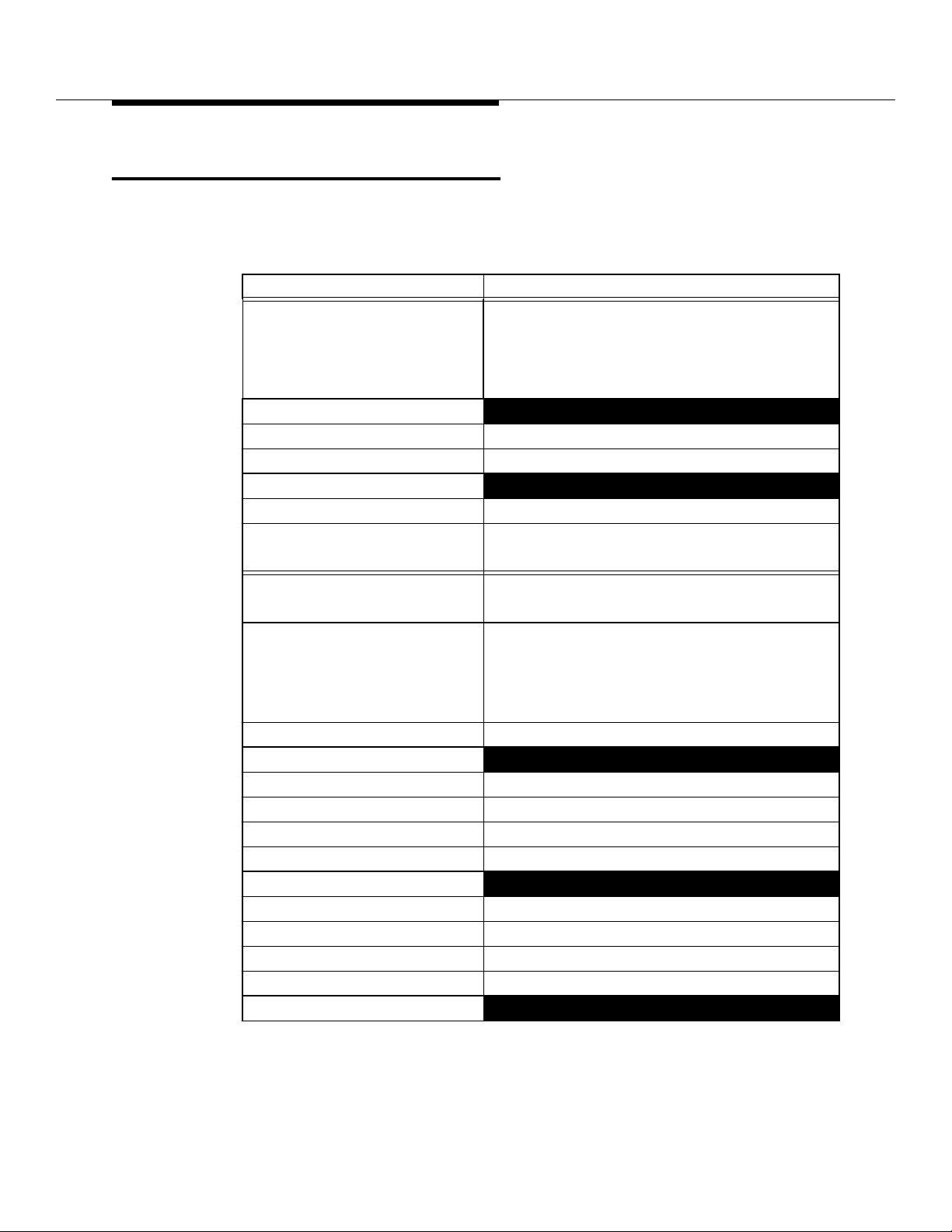
Table 8-15 provides a summary of Series II Cell Site Equipment.
Table 8-15. SIIe Cell Site, R5.06 or Later
Physical - Frames Description
P-RCF plus 1 or 2G-RCFs Primary RCF with 1, or 2 Growth Frames
1 or 2 LAFs (up to 7 LACs) 1, or 2 Linear Amplifier Frames
1 Primary AIF
1 Growth AIF
RCF Equipage P-RCF Shelves Same as in Companion Table
G-RCF Shelves Standard Series II product with 6 radio shelves
Radios
Radio Types RCUs, DRUs, and EDRUs
Locate 1-RCU, optional growth to a maximum number
allowed in standard Series II
Setup 1-RCU, optional growth to a maximum number
allowed in standard Series II
Voice 1-RCU/DRU/EDRU to a maximum allowed in any
combination subject to physically available
radio slots (depends on Setup RCU and Locate
RCU equipage)
Test RTU and optional "TRTU"
Communications and Clock
TDM Buses 1 or 2
DS1 Lines 1 or 2
Data Links 1 or 2
CAT Boards 2 per TDM Bus
Configuration
Radio Control Complex Redundant
Reference Frequency Generator Non-redundant, redundant optional
Receiver Calibration Generator Option al
Receive Switches Optional
Voice Sectorization
Lucent Technologie s — Propriet ary
See notice on first page
401-660-100 Issue 11 August 2000
8-83
Page 51
Series II Cell Site Equipment Descriptions
Table 8-15. SIIe Cell Site, R5.06 or Later (Contd)
Physical - Frames Description
Voice Omnidirectional and/or 1 to 6 Sectors
Setup Configurations
Configurations Omnidirectional or Directional
AIF Equipage Filter Panels Simplex or Duplex
Translations Developments - SIIe Translator
Series II Cell Site,
Related
Documentation
Table 8-16 below provides a list of supporting documentation. For instructions on
how to order this documentation, refer to Lucent Technologies 401-610-000,
Customer Documentation Catalog.
Table 8-16. Series II Cell Site - Related Documentation
Document Title Designation
Planning Guide 401-610-006
Data Base Update 401-610-036
Input Message Manual 401-610-055
Output Message Manual 401-610-057
System Routine and Corrective Mainte nance 401-610-075
ECP/CDN Recovery/Messages Audits Manual 401-610-077
Cell Site Audits Manual 401-610-078
System Recovery 401-610-079
Recommended Spare Parts, Tools, and Test Equipment 401-610-120
Service Measurements 401-610-135
Daily Operations 401-610-151
Multiple System Subscriber Administrati on (MSSA) 401-612-064
Series II Cell Site Diagnostic Test Descriptions 401-660-101
Series I and II Cell Translations Applications Guide 401-660-106
Cellular Operations Systems
Performance Analysis and Cellular Engi neering Users Guide
Series IIm T1/E1 Minicell Description, Operati on, and Mainte-
nance
AUTOPLEX System Application Schematic SD2R236,
Storage Battery Lead-Acid Type Requirements and Procedures 157-601-701
J86928A Power Plant Maintenance 167-609-309
401-660-108
401-660-115
Issue 7
8-84
Lucent Technologie s — Propriet ary
See notice on first page
401-660-100 Issue 11 August 2000
Page 52

Series II Cell Site Equipment Descriptions
Table 8-16. Series II Cell Site - Related Documentation (Contd)
Document Title Designation
J86928A Power Plant Description 167-609-310
J86928A Power Plant Rectifier Description 167-609-311
Cell Site Diagnostic Test Descriptions 401-660-101
Cell Site Antenna Equipment Installation Pla nning Guide 401-200-300
System Routine and Corrective Mainte nance 401-610-175
Cell Site I/O Manual 401-610-107
Recommended Spare Parts, Tools, and Test Equipment 401-610-120
Compact Base Station Description, Operation, and Maintenance 401-660-060
Microcell Implementation, Installation, and Maintenance 401-661-111
Protective Grounding Systems Requi rements 802-001-197
Electrical Protection of Radio Stations 876-210-100
Intro to Series II Compact Base Station
Introduction to Microcell CIB-191
Radio Channel Frame (Primary) Schematic Drawing SD-2R263
Radio Channel Frame (Growth) Schematic Drawing SD-2R264
Linear Amplifier Circuit Schematic Diagram SD-2R265
Linear Amplifier Frame Schematic Drawin g SD-2R266
Antenna Interface Frame Schematic Drawing SD-2R268
Series II Cell Site Schematic Drawing SD-2R271
ustomer
C
nformation
I
ulletin
B
(CIB)-182
Lucent Technologie s — Propriet ary
See notice on first page
401-660-100 Issue 11 August 2000
8-85
Page 53

Lucent Technologie s — Propriet ary
See notice on first page
8-86
401-660-100 Issue 11 August 2000
Page 54

Radios
Contents
Contents 9-1
■
Introduction 9-3
■
AMPS Radio Units and Personality Types 9-4
■
Radio Channel Unit (RCU) 9-4
Voice RCU (V-RCU) 9-5
Setup RCU (S-RCU) 9-6
Locate RCU (L-RCU) 9-6
Radio Test Unit (RTU) 9-7
TDMA Radio Units and Personality Types 9-8
■
Digital Radio Unit (DRU) 9-8
Enhanced Digital Radio Unit (EDRU) 9-8
Digital Radio Personality Types 9-8
Digital Voice Radio 9-8
Digital Control Channel (DCCH) Radio 9-9
Digital Beacon Radio 9-9
Digital Locate Radio 9-9
DRU - Detailed Description 9-10
EDRU - Detailed Description 9-11
9
Lucent Technologie s — Propriet ary
See notice on first page
401-660-100 Issue 11 August 2000
9-1
Page 55

Radios
Series II Cell Site, Enhanced Digital Radio Unit (EDRU)
Components 9-13
Series II Cell Site, Enhanced Digital Radio Unit (EDRU)
Interfaces 9-14
Enhanced Digital Radio Unit (EDRU) Reliability,
Federal Communications Commission (FCC), and
Safety Features 9-16
DRU/EDRU Power Supply 9-16
Directional Setup and Beacon Channels 9-16
TDMA Radio Test Unit (TRTU) 9-17
Test Enhanced Digital Radio Unit (T-EDRU),
Feature IDentification (FID) #2775 9-18
Cell Sites that can use the Test Enhanced Digital Radio
Unit (T-EDRU) 9-18
Testing Supported by the Test Enhanced Digital Radio
Unit (T-EDRU) 9-19
Test Enhanced Digital Radio Unit (T-EDRU) Connectivity 9-19
Test Enhanced Digital Radio Unit (T-EDRU) Testing of
C/T-EDRU, L-EDRU, and DCCH 9-21
Test Enhanced Digital Radio Unit (T-EDRU)
Bit-Error Rate (BER) 9 -21
Test Enhanced Digital Radio Unit (T-EDRU) Power
Requirements 9-21
MSC and TI OA&M for the Test Enhanced Digital Radio
Unit (T-EDRU) 9-22
CDMA Radio Maintenance Units and Personality Types 9-23
■
Pilot/Sync/Access Channel Element (CE) 9-24
Page CE 9-24
Traffic CE 9-24
Orthogonal-channel Noise Simulator CE 9-25
9-2
401-660-100 Issue 11 August 2000
Lucent Technologie s — Propriet ary
See notice on first page
Page 56

Radios
Introduction
The RCFs contain slots in to which cellul ar equipment and r adios are i nserted. The
P-RCF contains 4 shelves with 12 slots each and 1 shelf with 8 slots, for a total of
56 slots. Each Growt h RCF has 6 shelves of 12 slots each for a total of 72 slots.
Altogether, an RFS has 200 equipment/radio slots.
Up to two 8-bi t TDM b uses (T DM b us 0 and TDM b us 1) conne ct the r adio s helv e s
in the primary and Growth RCFs. TDM bus 0 serves 5 radio shelves (56 slots) in
the P-RCF and the 4 upper radio shelves (48 slots) in the first Gro wth RCF for a
total of 9 radio shelves (104 slots).
TDM bus 1 serves the 2 bottom radio shelves (24 slots) in the first g rowth frame
and the 6 radio shelves (72 slots) in the second growth frame for a total of 8 radio
shelves (96 slots).
Each of the 3 RCFs of an RFS can contain any combination of the following 3
types of radio units.
NOTE:
TDM buses are always installed "red stripe up."
Lucent Technologie s — Propriet ary
See notice on first page
401-660-100 Issue 11 August 2000
9-3
Page 57
Radios
AMPS Radio Units and Personality
Types
Radio Channel
Unit (RCU)
TECHNOLOGY
TYPE:
HARDWARE
TYPE:
PERSONALITY
TYPE:
The RCU is the analog radio used with the Advanced Mobile Phone Service
(AMPS) system. The RCU occupies 1 slot on an RCF shelf. 1 RCU provi des 1
analog channel. Because an RCU uses a single slot on a radio shelf, an RFS
fully-configured with RCUs can house 200 RCUs, i ncluding voice, setup, and
locate radios, providing 192 analog channels.
AMPS
SBRCU RTURCU
S-RCU V-RCU L-RCU
NVM IMAGE NVM IMAGE
S-SBRCU V-SBRCU L-SBRCU RTU
NVM
IMAGE
Figure 9-1. AMPS Radio Maintenance Units and Personality Types
For the RCU radio typ e , there is one non- volatile memory (NVM) image file f or the
setup radio (S-RCU), analog voice radio (V-RCU), and analog locate r adio
(L-RCU). At initialization, t he RCC downl oads the personality type and other
specific parameter values to each RCU. There is another NVM image file for the
RTU.
For the SBRCU radio type, there is one NVM image file for the S-SBRCU,
V-SBRCU, and L-SBRCU. As of ECP Release 8.0, the Cell Site software
downloads a new NVM image file to the SBRCU, separate and distinct from the
NVM image file downloaded to the RCU.
The Radio Channel Unit (RCU) is a plug-in module containing all RF, baseband,
and control circuitry required to perform setup, locate, or voice channel functions.
The RCU function, its operating channel, transmit power lev el, and other specific
parameters are downl oaded to each radio at initializat ion by the Time Division
Multiplexed (TDM) bus, which is always installed "red stripe up." In addition, RCU
call-processing algorithms are contained in nonvolatile memory within each unit
9-4
401-660-100 Issue 11 August 2000
Lucent Technologie s — Propriet ary
See notice on first page
Page 58

Radios
and can be updated by the TDM bus, if necessary. The downloadable parameter
and nonv olatile memory update features allow remote reconfigur ation of the RCU
and eliminate the need for many on-site visits.
The RCU also contains a Built-In Self Test (BIST) capabilit y and a m ultifunction
front panel display. BIST routines are automatically executed at initialization and
the test results reported to the Radio Control Complex (RCC). The display
includes channel number , funct ion, transmitte r-on, standby, and fail ure indications.
Also, there is a front panel switch which allows the transmitter to be shut off by a
technician independent of aut omati c control command.
What follows is a brief description of each AMPS radio personality type:
Analog voice radio: Performs the analog voice function_carries one
■
over-the-air AMPS call.
Setup radio: Performs the analog setup function_establi shes calls via the
■
analog control channel (ACC) with mobile subscribers using AMPS or
IS-54B compliant TDMA/AMPS dual-mode mobiles.
Analog locate radio: Performs the analog locate function. The Analog
■
locate radio assists with AMPS handoffs by measuring the mobile signal
strength and verifying the mobile supervisory audio tone (SAT).
Voice RCU (V-RCU)
The receiver section of a Voice Radio Channel Units (V-RCUs) receives Radio
Fr equency (RF) input from the Cell Site receiving antenna (two inputs for
diversit y). This input can be supplied from omni receivi ng antennas or from
receiving antennas on one of the faces of the directional antennas.
The Radio Channel Unit (RCU) receiver passes voice audio into its baseband
circuits where it is processed and applied through a trunk back to the Mobile
Switching Center (MSC). The data output from the receiver is applied to its data
decoder circuits where it i s decoded and applied to the on-l ine Cell Site proces sor .
Data transmission on the receive voice channel is referred to as reverse
blank-an d-burst data. During data transmission by the subscriber unit, the voice
channel is blanked for a small interval while a burst of data is sent. The voice
receivers also play a part in the handoff function by periodically making signal
measurements.
Voice signals to be transmitted are sent from the MSC by a trunk and applied to
the RCU where they are processed and applied to the RCU’s tran smitter. The
modulated transmitter RF output is appl ied to the Linear Amplifier Unit (LAF) and
then through the Antenna Interface Frame (AIF) to the antennas.
Data to be transmitted is applied from the on-line Cell Site processor to the data
encoder circuits on t he RCU where it is f ormatted and appli ed to the tran smitter f or
transmission. Tran smitter and receiver tuning is accomplished by a synthesizer
Lucent Technologie s — Propriet ary
See notice on first page
401-660-100 Issue 11 August 2000
9-5
Page 59

Radios
which is controlled by a common input. A 15.0-MHz synthesizer reference
frequency is applied from the Reference Frequency Generato r (RFG) located in
the AIF.
An RCU or SBRCU having a voi ce radio personal ity ma y also ha v e a beacon radio
personality. Thus, an RCU or SBRCU can serve two functions concurrently: (1)
carry an over-the-air AMPS call and (2) pro vi de signal strengt h measureme nts f o r
the TDMA mobile-assisted handoff (MAHO) procedure. Since the RF carrier
power level remains fixed for beacon radios, the dual-personality RCU or SBRCU
is ineligible for dynamic power control.
Setup RCU (S-RCU)
Normally, two Radio Channel Units (RCUs) are designated as Setup Radio
Channel Units (S-RCUs). Setup radios perform the receive and transmi t functions
required to set up a cal l. Be cause of the dual f unct ion (r eceivi ng and t r ansmitti ng),
setup radios pro vide both paging and accessing functions. Paging refers to the
process of call ing a ce llular subs criber ( Cell Site t o cel lular su bscriber) . Access in g
refers t o t he process of the c ellul ar s ubscriber making a call (cell ul ar subscri ber to
Cell Site). The Radio Frequency (RF) output of t he s etup r adios i s ampli fied by th e
Linear Amplifier Frame (LAF) and then fed to the transmit antenna through the
Antenna Interface Frame (AIF).
With Release 4.3, the Simulcast Setup feature allowed setup radios to transmit
signals to all directional v oice sectors and rec eive si gnals from all dire ctional v oice
sectors in a Cell Site using a si ngle set up channe l frequency. In this confi gur ati on,
a single setup channel serves the entire Cell Site. This contrasts with directional
setup for which each directional v oice sector has its own setup channel and its
own pair of redundant setup radios. Simulcast setup also contrasts with
omnidirectional setup which requires an omnidirectional antenna and associated
Linear Amplifier Circuit (LAC).
Locate RCU (L-RCU)
Some Radio Channel Units (RCUs) are designated as "Locate"RCUs (L-RCUs).
L-RCUs perform the locate function requir ed to determine if a handoff is needed.
Signal measurements are made periodically by the locate receivers within Cell
Sites adjacent to the Cell Sit e serving the subscriber’s unit. When it is determined
that an adjacent Cell Site can serve the subscriber bet ter, a handoff is made to
that adjacent Cell Site.
Any of the RCUs may be designat ed a locat ing radio. Frequency control data is
applied to the receiver’s frequency synthesizer to t une the lo cating radio to the
channel being monitored. A reference frequency is supplied to the receiver’s
synthesizer fr om the Reference Frequency Generator (RFG) l ocated in the
Antenna Interface Frame (AIF).
9-6
401-660-100 Issue 11 August 2000
Lucent Technologie s — Propriet ary
See notice on first page
Page 60

Radios
Diversity receiving antennas are used for all omnidirectional and directional
antenna configurations. This means that each Cell Site RCU has two recei ving
Radio Frequency (RF) inputs, referred to as 0 and 1.
Received signal s fr om the Cell Sit e receiving antennas are applied to the switch/
combiner board in the Primary Radio Channel Fr ame (P-RCF). The P-RCF is
wired to receive two omni receive inputs and two receive inputs from each
directional face. Use of these RF inputs depends upon the ante nna configuration
options employed at the Cell Site. RF switches within the switch/combiner board
provide individual RF selection for each RCU. This means that up to two omni
receive input s or directional receive inputs can be selected and applied to each
setup RCU and that the locating RCUs may receive up to either two omni receiv e
inputs or two directional receive inputs from any one of the directional faces. In
addition to the switchable antenna configuration provided by the switch /combiner
board, a fixed antenna configuration is also used.
Radio Test Unit
(R TU)
The Radio Test Unit (RTU) pro vides Radio Fr equency (RF) testing of all Radio
Channel Units (RCU)s. Under software control, diagnostic test paths are
established to test and measure all major RF functional operations. The RTU
contains a test receiver and test generator whi ch serve to simulate a subscriber’s
unit. The test receiver can be tuned to any subscriber’s receive channel, and the
test generator can be tun ed to any subscriber’s transmit channel. Tuning is
accomplished by the RF test frequency control input to a transmit/receive
frequency synthesi zer wi thin t he R TU. The reference frequency, supplied from the
internal Reference Frequency Generator (RFG), provid es the synthesizer
reference. The RTU can be switched into a self-test mode to mak e a loop-around
test.
During receiver te sting on an RCU, test data is encoded and applied from the
RTU. The test generator with in th e RTU is tuned to the channel under test, and
the output of the test generator is applied to the appropriate Cell Site receiving
antenna’s directional coupler. Control is applied to the Radio Test Unit Switch
Panel (RSP) in the Antenna Interface Fr ame (AIF) to select the correct antenna.
The test generator can inject the test signal (as selected by the RTU) into either
the forward or reflected port of a directional coupler associated with the RCU
under test.
Test data injected into the refl ected port of the directional coupler is seen by the
receiver under test as a normal incoming signal. The receive si gnal and data are
ev aluat ed and the res ults sent to the Mobi le Switch ing Center (MSC). Test signals
injected into the forward port of the directional coupler are seen by the receiver
under test as a reflected in put. Receiving antenna efficie ncy can be measured by
comparing (obtaining a ratio of) receive signal strength resulting from reflected
and forward signal injection.
Lucent Technologie s — Propriet ary
See notice on first page
401-660-100 Issue 11 August 2000
9-7
Page 61

Radios
TDMA Radi o Units an d Personality
Types
The two types of TDMA digital radios are briefly explained below.
Digital Radio Unit
(DRU)
Enhanced Digita l
Radio Unit
(EDRU)
The DRU is the digital radio used with the Time-Division Multiple Access (TDMA)
system. The DRU occupies 2 slots on an RCF shelf. The DRU supports 3
full-duplex Digital Traffic Channels (DTCs) on one 30-kHz bandwidth RF channel
via Time-Division Multiplexing. Given that the DRU occupies 2 slots, the number
of DR Us that can be h oused in th e P-RCF is half the n umber of RCUs , whic h is 28
DRUs. For the 2 Growth RCFs, the number of DRUs that can be housed is also
half the number of RCUs, that is , 36 DRUs apiece. Altogether, an RFS
fully-configure d with DR Us can ho use 9 9 DR Us , incl uding vo ice and loc ate r adios .
The software can support 256 DTCs. (Call setup is done by the DCCH with no
setup radios r equired). The DRU is tested using a TDMA Radio Test Unit (TR TU).
The EDRU is an enhanced version of the DRU that is fully backward compatible
with the DRU. The EDRU improves (i.e., enhances) many of the features offered
by the DRU. Additionally, the EDRU provides new features and capabilities that
the DRU cannot offer. The EDRU occupies 1 slot on an RCF shelf. That is, two
EDRUs can be inst alled f o r ea ch DRU. Like the DRU, the EDRU supports 3 DTCs.
Each of the 3 channels can carry either Control information or Traffic (C/T).
Because the EDRU, like the RCU, occupies only 1 slot on a radi o shelf, the
Primary RCF has enough radio slots for 56 EDRU s, and the Growth RCFs have
enough radio slots for 72 EDRUs apiece.
However, a 430AB power converter unit is required to support a maximum of 8
EDRUs per shelf . Additio nally, due to softwa re limit ations , the maxim um number of
EDRUs supported are:
■
■
■
■
Digital Radio
Personality Types
The following paragraphs provide a brief description of each TDMA radio
personality type:
Digital Voice Radio
Pe rforms the digital traffi c channel f unction_ carries up to th ree o v er -the-air TDMA
calls.
9-8
401-660-100 Issue 11 August 2000
RCF0: 23 EDRUs
RCF1: 40 EDRUs
RCF2: 16 EDRUs
Total: 79 EDRUs The t otal number of EDRUs per cell should not exceed 79 ,
including voice and locate r adios. Call setup is done by the DCCH with no
setup radios required. The EDRU is tested using a TRTU.
Lucent Technologie s — Propriet ary
See notice on first page
Page 62

Radios
Digital Control Channel (DCCH) Radio
Pe rforms the digital setup and short message service functions_ estab lish es calls
via the DCCH with mobile subscribers using IS-136 compliant TDMA/AMPS
dual-mode mobiles. The DCCH is carried on user channel 1. Typically, there is
one DCCH per physical antenna face, or sector, in a TDMA system.
Digital Beacon Radio
Performs the digit al beacon channel functi on_transmits at a fixed l evel at all times
to provide signal strength measurements for the TDMA MAHO procedure.
Typically, there is one beacon radio per physical antenna face in a TDMA system.
Digital Locate Radio
Performs the digital locate channel function_assists with handoffs when the
establishe d TDMA call can be better served by an adjacent sector or cell by
measuring the signal strength and ve rifying the digital v erif ication color code
(DVCC) of the IS-54B or IS-136 compliant TDMA/AMPS dual-mode mobile
targeted for handoff. The digi tal locate radio is instrumental in the DVCC
verification procedure.
For the DR U r adio type , there is one NVM image file f or the digit al contr ol channel
radio (D-DRU), digital voice radio (V-DRU), and digital beacon radio (B-DRU). At
initialization, the RCC downloads the personality type and other specific
parameter val ues to each DRU. There is another NVM image file for the digital
locate radio (L-DRU), and still another for the TRTU.
A DRU or EDR U provi des a basic modulatio n efficiency of t hree user channel s per
30-kHz of bandwidth. The three user channels are designated user channel 1,
user channel 2, and user channel 3. Each user channel is assigned one trunk
(DS0) on the T1 line and one du ple x ti meslot on the RCF internal TDM bus , whi ch
is always installed "red stripe up ."
A D-DRU or D-EDRU may also carry digital traf fic and beacon channels. Thus , a
D-DRU or D-EDRU can serve three functions concurrently: (1) perf orm the digital
setup function _establish cal ls via the DCCH wit h mobile subscribers us ing IS-136
compliant TDMA/AMPS dual-mode mobiles , (2) carry one or two over-the-air
TDMA calls, and (3) provide signal strength measurements for the TDMA MAHO
procedure. Since the RF carrier power level remains fixed for DCCH radios, the
D-DRU or D-EDRU is ineligible for dyna mic power control.
The EDRU, unlike the DRU, will be able to carry more than one DCCH. That is, in
a future release, an EDRU will be able to carry one, two, or three DCCHs.
A B-DRU or B-EDRU may also carry digital tra ff ic channels. Thus, a B-DRU or
B-EDRU can serve two functions concurrentl y:
Lucent Technologie s — Propriet ary
See notice on first page
401-660-100 Issue 11 August 2000
9-9
Page 63

Radios
(1) provide signal strength measurements for the TDMA MAHO procedure and
(2) carry one, two , or even three ove r-the-air TDMA calls. (A digital beacon
channel may double as a digital traffi c channel.) Since the RF carrier power level
remains fixed for beacon radios, the B-DRU or B-EDRU is ineligible for dynamic
power control.
A V-DRU or V-EDRU may only carry digital traffic channels. A V-DRU or V-EDRU
can carry one, two, or three digital traffic channels.
An L-DRU ma y only carry digital locate channel s. An L-DR U can carry one, tw o , or
three digital locate channels.
DRU - Detailed
Description
The Digital Radio Unit (DRU) is the digital radio used with th e Time-Di vision
Multiple Access (TDMA) system. The DRU is entirely digital, self contained,
comes with all the software needed to support TDMA, and does not need any
additional equipment to support call processing.
The DRU plugs i nto t he same co nnect ors as th e Radio Ch annel Uni t (RCU) that is
used with AMPS Systems. However, whereas the RCU occupies 1 slot in a Radio
Channel Frame (RCF), the DR U occu pies 2 sl ots in an RCF. Then again, the RCU
provides only 1 analog channel, whereas the DRU supports 3 full-duplex Digital
Traffic Channels (DTCs) on one 30-kHz bandwidth RF channel via Time-Division
Multiplexing. The DRU can support control information (DCCH) on 1 of its
channels and (voi ce) Traffic on the other 2 channels. If the Cell Site supports the
Digital Control CHannel (DCCH) f e ature, the DCCH will perf orm the setup function
for digital calls and no setup radios will be req uired. (Setup radios will stil l be
required for analog calls).
The DR U’s dimensions are nominally 8 inches high by 3 inches wide by 14 inches
deep. Although the DRU is twice as wide as the RCU and occupies 2 slots as
compared with 1 slot for the RCU, DRUs and RCUs can sit side-by-side on the
same RCF shelf.
The combination of DR Us and RCUs allo wed on a 12- slot RCF shel f is as f oll o ws:
(2 x Number of DRUs) + (Number of RCUs) = 12 slots
9-10
The Radio Test Unit (RTU) shelf of an RCF contains 8 available slots. Therefore,
the combination of DRUs and RCUs allowed on the 8-slot RCF is as follows:
(2 x Number of DRUs) + (Number of RCUs) = 8 slots
The placement of DRUs on a radio shelf in constrained as follows. W hil e the DRU
uses 2 RCU slots, it mak es contact with onl y 1 back pla ne slot. That sl ot is the one
on the left if one is viewing the equipment fr om the fro nt. To place the maximum
number of DRUs on a shelf, the DRU must be installed so that it makes contact
Lucent Technologie s — Propriet ary
See notice on first page
401-660-100 Issue 11 August 2000
Page 64

Radios
with the ev en-numbered RCU slot. On an RCU shelf, for example, the valid
locations for 6 DRUs would be RCU slots 0-1, 2-3, 4-5, 6-7, 8-9, and 10-11. The
connections would be at slots 0, 2, 4, 6, 8, and 10.
On RCF shelves c onta ining 12 RCU sl ots , +5 Volts DC power is pro vi ded b y 1 of 2
units; The 415 AA DC/DC unit and the 415 AC DC/DC unit. The power converter
used depends on the combination of RCU and DRU/EDRU units on the shelf.
Table 9-1. 415 AA/AC DC/DC Power Unit
415AA DC/DC power supply 415 AC DC/DC po wer unit
DRUs/EDRUs RCUs DRUs/EDRUs RCUs
1 DRU/EDRU 10 RCUs 4 DRUs/EDRUs 4 RCUs
2 DRUs/EDRUs 8 RCUs 5 DRUs/EDRUs 2 RCUs
3 DRUs/EDR Us 6 RCUss 6 DRUs/EDR Us 0 RCUs
An important feature that increases the flexibility of the system and protects your
invest ment i n the DRU is the ability to do wnload the DRU’s software/fi rmware from
the Mobile Switching Center (MSC). This makes it quick and easy to
accommodate future revisions in the IS-54A standard and reduces down-time for
upgrades.
EDRU - Detailed
Description
The DRU consists of 2 modules . One is the Signal Processing Module (SPM),
which contains 3 circuit boards . The other is the Transceiver Circuit Module
(TCM), which contains one circui t board. The DRU is tested using a TDMA Radio
Test Unit (TRTU). The DRU faceplate provides a channel display and LED status
indicators.
The DRU is also used t o support the Digital Control CHannel (DCCH) f eat ure. F or
information regarding how the DRU is used to support the DCCH, please see the
appropriate section in this document.
The Enhanced Digital Radio Unit (EDRU) is an enhanced version of the Digital
Radio Unit (DRU) that is used wi th Ti me Divi sion Multiple Access (TDMA)
systems. The EDRU is fully back-compatib le wi th the DRU and can perform all the
functions of a DRU. When the EDRU is used to perform the same functions that a
DRU performs, it uses the same commands.
Like the DR U, the EDRU supports 3 full-duplex Digital Traff ic Channel s (DTCs) on
one RF channel via Time-Divisi on Multiple xing. Ho we ver, the EDRU occupies only
1 radio slot, whereas the DRU occupi es 2. The EDR U’s dimensions are nominally
those of the Radio Channel Unit (RCU):
Height: 7.67 inches.
Width: 1.5 inches.
Lucent Technologie s — Propriet ary
See notice on first page
401-660-100 Issue 11 August 2000
9-11
Page 65

Radios
Depth: 14.15 inches, inclu ding the connector and face pl ate that extends
from the EDRU.
Depth: 13.86 inches, excluding the connector and face plate that extends
from the EDRU.
RCUs, DRUs, and EDRUs can sit side-by-side on the same RCF shelf.
If the Cell Site supports the Digital Control CHannel (DCCH) feature, the DCCH
will perf orm the set up funct ion for digital calls and no setup r adios wi ll be requi red.
(Setup radios will stil l be required for analog calls).
The Time Division Multiple Access (TDMA) Systems that support Enhanced
Digital Radio Unit (EDRU) Implementation are the Series II, IIm (mini) , IImm
(micro-cell), IIe (enh anced), Compact Base Station (CBS), and P ersonal
Communications Services (PCS) TDMA Minicell.
The EDRU complies with the standards that define control, traffic, and data
operations for both cellular and PCS TDMA systems. Unless explicitly stated
otherwise, the EDRU contains all features specified in thi s document for both
cellular and PCS operations. The EDRU is softw are-configurable as the 2 radio
types that follow:
1. Control/Traffic radio (C/T-EDRU) When the EDRU is configured as a C/
T-EDRU it sup ports DCCH or DTC func-tional ity in a n y combinat ion for any
of the 3 full-duple x channels it provides . The C/T- EDRU supports DTC
structure for the forward and reverse digital tr affic channels as defined in
the standards for TDMA frame format, time-slot format, data rate, and
timing relationships. The C/T-EDRU suppor ts the following config-urations
for DTC and DCCH on the same RF carrier.
Table 9-2. C/T EDRU Configurations
C/T EDRU Configurations
Configuration Time Slot 1 Time Slot 2 Time Slot 3
1 DTC DTC DTC
2 DCCH DTC DTC
Digital Verification Color Code (DVCC) detection
■
Receive Signal Strength Indicat or (RSSI) Esti mates . In addition, the
■
EDRU can perform any of these functions for PCS systems if
external frequency conversion is provided.
2. Locate Radio (L-EDRU)
The Locate Radio performs the following:
9-12
Diagnostics and Functional Tests
■
Lucent Technologie s — Propriet ary
401-660-100 Issue 11 August 2000
See notice on first page
Page 66

Radios
Power level measurements
■
Series II Cell Site, Enhanced Digital Radio Unit (EDRU) Components
The two modules in the Enhanced Digital Radio Unit (EDRU), and the functions
they perform, are outlined below:
1. Transceiver Circuit Module (TCM):
a. The EDRU’s TCM uses a transmitter to:
Up-convert baseband signals f rom the Signal Processing
■
Module (SPM) to digitally modulated Radi o Frequency (RF)
signals
Send the digitally modulated RF signals to the RF output
■
ports
The transm itter’s 4 components are:
— Up-Converter
— Amplifiers
— Filters
— Power Control Circuits
b. The EDRU’s TCM uses a receiver to:
Down-convert digitally modulated RF signals from the RF
■
input ports to baseband signals.
Send the baseband signals to the demodulator (SPM).
■
The receiver’s 4 major components are:
— Down-Converter
— Amplifiers
— Filters
— Gain Control Circ ui ts
The TCM contains the EDRU RF circuitry and uses the power
converter voltages below:
+12 VDC-RF
■
-12 VDC power converter voltages.
■
2. Signal Processing Module (SPM): Contains the EDRU’s digital circuitry.
The major components in the SPM are the Digital Signal Processors
(DSPs) that perform the necess ary functions b y exe-cuting the code stored
in the firmware. The functions of the SPM are:
Lucent Technologie s — Propriet ary
See notice on first page
401-660-100 Issue 11 August 2000
9-13
Page 67

Radios
Communicating with the Radio Channel Complex (RCC) via the
■
Time Division Multiplex (TDM) bus, which is always installed "red
stripe up." The EDRU provides the capabili ty to transmit uplink
(EDRU to RCC) messages and to r eceive downlink (RCC to EDRU)
messages over the TDM bus.
Supervising TCM Operations
■
Speech Coding and De coding
■
Channel Coding and Decoding
■
Interleaving and De-I nterleaving
■
Formatting and Defor matting
■
Modulating and Demodulating
■
Providing Equalization
■
Providing Echo Cancellation
■
Providing Receive Signal Strength Indicator (RSSI) Est imat es.
■
The three functions listed below are performed differently for Digital Traffic
Channels (DTCs) and Digital Control CHannels (DCCHs).
1. Channel Coding/Decoding
Series II Cell Site,
Enhanced Digita l
Radio Unit
(EDRU) Interfaces
2. Interleaving/De-Interleaving
3. Formatting/Deformatting Features. The SPM contains the EDRU
Digital Circuitry, and it uses the power converter voltages below:
+12 VDC
■
-12 VDC
■
+5 VDC
■
To prevent noise from disturbing the RF circuitry, no digital circuitry in the
entire system is permitted to use the +12 VDC- RF pow er con verter v oltage ,
which is different from the +12 VDC.
The EDRU heat dissipat ion does not exceed 43.9 W.
The Series II Cell Site, Enhanced Digital Radio Unit (EDRU) Backplane
Connection features Fa stech backplane conne ctor s in the Radio Channel Frame
(RCF) that provide the Enhanced Di git al Radio Unit (EDRU) with the 4 following
interfaces:
1. Radio Frequency (RF)
To provide receive diversity, the EDRU has 2 external RF input
■
(receive) ports via backplane connections.
The EDRU has 1 external RF output (transmit) port via a backplane
■
con-nection.
9-14
Lucent Technologie s — Propriet ary
See notice on first page
401-660-100 Issue 11 August 2000
Page 68

Radios
2. Reference Frequency
The EDRU has 1 external reference fr equency input port via a
■
backplane connecti on.
3. DC Power
The EDRU operates appropriately when all its supply voltages are within
5% of their nominal values. The maximum EDRU current drain on supply
voltages of the 4 interfaces is as follows:
Current drain for +12 VDC-RF source is 1.0 A
■
Current drain for -12 VDC source is 0.2 A
■
Current drain for +12 VDC source is 0.2 A
■
Current drain for +5 VDC source is 5.0 A
■
4. Digita l Signal
The EDRU has an external TDM bus interfac e to connect to the TDM bus via the
backplane. The TDM bus is always installed "red stripe up."
In the Series II and Series IIe Cell Sites, the EDRU is con nected to either TDM
bus 0 or TDM bus 1, dependi ng on where the EDR U is installed in the f rame. Each
TDM bus has 2 sides, an "A side"and a "B side,"for redundancy. Only 1 side is
active at an y given time. TDM buses are always installed "red stripe up."
In other systems, that are not Series II or Series IIe Cell Sites, the EDRU is
connected to only 1 TDM bus. That TDM bus also has an "A side"and a "B side."
The interfaces specified here are for the 2 sides of whichever TDM bus is serving
the EDRU. The EDRU uses the active TDM bus to communicate with the RCC.
Environmental Features:
Internal Cabinet Temperature: From 0x C to 65x C.
■
Humidity: From 5% relative humidity to the lesser of 95% relative humi dit y
■
or 0.024 g water vapor per gram of dry air over the internal cabinet
temperature range.
Altitude: From 200 feet below sea level to 10,000 feet above sea level.
■
Lucent Technologie s — Propriet ary
See notice on first page
401-660-100 Issue 11 August 2000
9-15
Page 69

Radios
Enhanced Digita l
Radio Unit
(EDRU)
Reliability , Federal
Communications
Commission
(FCC), and Safety
Features
The follo w ing lists the EDRU rel iability, FCC and safety features:
The reliability of the Enhanced Digital Radio Unit (EDRU) is less than 2500
■
FIT, equating to a MTBF of 400,000 hours.
The us e ful lifetim e of the EDRU is 7 years.
■
The EDRU complies with the appli cable fea tures in Part 2, Part 15, and
■
Part 22 of the FCC regulations.
The EDRU in conjunction with the up-bander complies with the applicable
■
fea-tures in Part 24 of the FCC regulations.
The EDRU is UL-1950 approved.
■
DRU/EDRU Power Supply
On RCF shelves c onta ining 12 RCU sl ots , +5 Volts DC power is pro vi ded b y 1 of 2
units; The 415 AA DC/DC unit and the 415 AC DC/DC unit. The power converter
used depends on the combination of RCU and DRU/EDR U unit s on the shelf. For
the purposes of the table below, the DRU and EDRU are equival ent. An important
feature that increases the flexibility of the system and protects your investment in
the DRU is the abili ty to download the DRU’s software/firmware fr o m th e.
Table 9-3. 415 AA/AC DC/DC Power Unit
415AA DC/DC power supply 415 AC DC/DC po wer unit
DRUs/EDRUs RCUs DRUs/EDRUs RCUs
1 DRU/EDRU 10 RCUs 4 DRUs/EDRUs 4 RCUs
2 DRUs/EDRUs 8 RCUs 5 DRUs/EDRUs 2 RCUs
3 DRUs/EDR Us 6 RCUss 6 DRUs/EDR Us 0 RCUs
Directional Setup
and Beacon
Channels
9-16
401-660-100 Issue 11 August 2000
An important feature that increases the flexibility of the system and protects your
invest ment i n the DRU is the ability to do wnload the DRU’s software/fi rmware from
the Mobile Switching Center (MSC). This makes it quick and easy to
accommodate future revisions in the IS-54A standard and reduces down-time for
upgrades.
The DRU consists of 2 modules . One is the Signal Processing Module (SPM),
which contains 3 circuit boards . The other is the Transceiver Circuit Module
(TCM), which contains one circui t board. The DRU is tested using a TDMA Radio
Test Unit (TRTU). The DRU faceplate provides a channel display and LED status
indicators.
The DRU is also used to support the Digital Control CHannel (DCCH) feature.
Only a Radio Channel Unit (RCU) c an be us ed for analog setup, but a DRU/EDRU
may be used f or digital setup. When the directional setup option is chosen, the
entire LAC and antenna system previously used for omnidirectional setup may be
Lucent Technologie s — Propriet ary
See notice on first page
Page 70

Radios
eliminated. Directional setup radios use the same antennas as do the voice
radios. When there is directional setup in a cell, the mobile-assisted handoff
feature of the DMMS transceivers scans the directional setup channels or the
beacon channels to determine a candidate list of faces to hand off to .
Omnidirectional setup is an opt ion to the service provi der. However, after Release
5.0, if omnidirectional setup is implemented in a Cell Site with directional voice
sectors, then beaco n channels must be provided to support the mobile-assiste d
handoff capabilit y for DMMSs. With no directional setup in a Cell Si te, the DMMSs
scan the beacon radio frequenci es f or that Cell Site . A beacon channe l is provided
by a designated voice radio which transmi ts i ts carrier at a constant power level.
Each antenna sector in a Cell Site must be allocated one beacon channel.
Beacon channels are provided at the request of the service provider and are
required only when the Cell Site has direct ional v oice wit h omni setup , or when the
Cell Site is equipped entirely with analog RCUs and the neighboring Cell Site is
equipped with digital channels.
Other setup options are simulcast setup or DCCH setup.
Setup radios are installed in the top radio shelv es of t he P-RCF. Normally, at
start-up, two setup radios (one active and one standby) are used.
TDMA Radio Test
Unit (TRTU)
The TDMA Radio Test Unit (TRTU) is a plug-in unit required in the P-RCF to test
the Digital Radio Units (DRUs) and other DR U-related equipment. It is one of
sev eral test units in the Primary Radio Channel Frame (P-RCF). The RTU tests
the analog Radio Control Units (RCUs).
The TRTU is composed of two functi onal groups
1. the Transceiver Functional Group and the
2. Signal Processing Functional Group.
The Transceive r Functional Group tests RF-related functions. The Signal
Processing Functional Group tes ts baseband speech processing, speech,
channel and message coding, equalization, and communication. The TRTU
exchanges messages with other equipment in the P- RCF via a TDM bus , whic h is
alwa ys installed "red stripe up."
The RTU Control Board (RCB) is used to multiplex the communication between
the RTU and TRTU and the RTU Switch Panel (RSP). The RSP allows the
appropriate test unit, TR TU or RTU , to test the DR U or RCU , respectiv ely. There is
a cabling kit to route the RF signal s to and from the appropriate test unit. Frames
ordered from the fa ctory come with the option built in. For frames already in the
field, there is a package available for field installation.
Lucent Technologie s — Propriet ary
See notice on first page
401-660-100 Issue 11 August 2000
9-17
Page 71

Radios
Test Enhanced
Digital Radio Unit
(T-EDRU), Feature
IDentification
(FID) #2775
Height 8.00 inches 8.00 inches
Depth 14.15 inches 14.15 inches
Width 3.00 inches 3.00 inches
Test Capability TRTU (Tests DRUs and EDRUs) T-EDRU (Tests EDRUs only)
SBRCU slots used 4 SBRCU slots 2 SBRCU slots
RCU slots used
Cell Si tes that can use the Test Enhanced Digital Radio Unit (T-ED RU)
This chapter cov ers the "Test Enhanced Digital Radio Unit (T-EDRU)"feature,
which has Feature IDentification (FID) #2775. The Test Enhance d Digital Radio
Unit (T-EDRU) is a more advanced alternative to the older TDMA Radio Test Unit
(TRTU) for testing EDRUs, but not DRUs. The T-EDRU may be used in all Series
II Classic, Series IIe , Series IIm, Series IImm and PCS TDMA Minicell Products
that are equipped with EDRUs only. The functionality on the TDMA Radio Test
Unit (TRTU), which is used to tes t DRUs and EDRUs, is identically replicat ed on
the Test Enhanced Digital Radio Unit (T-EDRU). However, the Test Enhanced
Digital Radio Unit (T-EDRU) takes up half the space of the TRTU and is used to
test EDRUs only.
The Test Enhanced Digital Radio Unit (T-EDRU) is identical in terms of hardware
and physical size to the Enhanced Digital Radio Unit (EDRU). The only difference
between it and the Enhanced Digital Radio Uni t (EDRU) is that a different
Non-Volatile Memory (NVM) software/firmware image is downloaded into it from
the Radio Control Complex (RCC) over the Time-Division Mul ti pl exed (TDM) bus,
which is always installed "red stripe up."
Table 9-4.
Placement and Use of the Test Enhanced Digital Radio Unit (T-EDRU)
Dimensions and Placement
TRTU T-EDRU
2 RCU slots 1 RCU slot
9-18
The Test Enhanced Digital Radio Unit (T-EDRU) and the TDMA Radio Test Unit
(TRTU) are not supported in the same base station at the same time. Only one
TDMA test radio, either the TDMA Radio Test Unit (TRTU) or the Test Enhanced
Digital Radio Unit (T-EDRU) is required per base stat ion. One Test Enhanced
Digital Radio Unit (T-EDRU) is enough to test the Enhanced Digital Radio Units
(EDRUs) in one or more radio frames, equipped wit h EDRUs only, within a single
cell site. Li ke the TDMA Radio Test Unit (TRTU), the Test Enhanced Digital Radio
Unit (T-EDRU) is l ocated in the radio test slot of the Primary Radio Channel
Fr ame (P-RCF) at the cel l site . Bec ause only 1 Test Radio is used per cell site, if it
fails, all diagnostic testing that requires the Test Radio must be suspended.
The Test Enhanced Digital Radio Unit (T-EDRU) is placed in the 2 lower
numbered Time-Division Multiplexed (TDM) bus addresses currently used by the
Lucent Technologie s — Propriet ary
See notice on first page
401-660-100 Issue 11 August 2000
Page 72

Radios
TDMA Radio Test Unit (TRTU) fo r all Series II products and the TDMA PCS
Minicell. TDM buses are always installed "red stripe up."
Only in the case of the Series IImm can a Control/Traffic Enhanced Digital Radio
Unit (C/T-EDR U) or a Locate EDRU (L-EDRU) be allowed to occupy and operate
in the 2 higher numbered Time-Divi sion Multiplexed (TDM) bus addresses, which
are also the 2 av ail able Single Board Radio Channel Unit (SBRCU) slots next to
the Test Enhanced Digital Radio Unit (T-EDRU). This capability is not supported
on other products. The 2 slots f or the Control/Traffi c in the Series II mm have been
designed to support receive a nd tra nsmit f unct ions to these bac k plane sl ots. Also,
the amplification scheme in the Series IImm products allow for the addition of
another radio.
Testing Supported by the Test Enhanced Digital Radio Unit (T-EDRU)
The Test Enhanced Digital Radio Unit (T-EDRU) is functionally backward
compatible with the TDMA Radio Test Unit (TRTU). Additionally, it supports all
functional, diagnost ic, and measurement testing of the following:
Enhanced Digital Radio Units (EDRUs) (In Any Configuration)
■
Radio Frequency (RF) Switches
■
Transmit Antennas
■
Receive Antennas
■
Lightwave Microcell Transceiver (LMT)
■
Lightwave Microcell Transceiver (LMT) Optical Link.
■
Functional tests are performed when a radio is in service. Diagnostic and
measurement tests are performed when a radio is out of service.
Test Enhanced Digital Radio Unit (T-EDRU) Self-Test 0
As part of Lucent’s maintenance strategy, the Test Enhanced Digital Radio Unit
(T-EDRU) tests itself before it tests the other radios. The self-diagnostics
performed by the Test Enhanced Digital Radio Unit (T-EDRU) include measuring
the following:
Transmit Power Level
■
Received Signal Str ength Indicator (RSSI) Integ rit y
■
Time Alignment
■
Radio Frequency (RF) Signals on the Switchable Shelf
■
Test Enhanced Digital Radio Unit (T-EDRU) Connectivity
The Test Enhanced Digital Radio Unit (T-EDRU) simulates a mobile station in
order to test the TDMA radios and any other TDMA related equipment in the cell
Lucent Technologie s — Propriet ary
See notice on first page
401-660-100 Issue 11 August 2000
9-19
Page 73

Radios
site. Failures are treated the same as a TDMA Radio Test Unit (TRTU). The Test
Enhanced Digital Radio Unit (T-EDRU) provides a control lead and an RS-422
interface to the Radio Test Unit (RTU) Communicat ions Board (RCB). The Radio
Test Unit (RTU) Communicat ions Board (RCB) is used to provide Radio
Fr equency (RF) connectivity to the Radio Test Unit (RTU) switch panel.
Radio Control Complex (RCC) Generic Maintenance Software Capability 0
Generic maintenance software in the Radio Control Complex (RCC) can:
Control the Test Enhanced Digital Radio Unit (T-EDRU) transmit and
■
receive antenna switches.
Transmit Radio Frequency (RF) signals to TDMA radios located on
■
switchable shelves to test the receive paths thr ough the antenna switches.
Transmit Radio Fre quency (RF) signal s directly to TDMA radios , then to the
■
receive antennas, for performing return loss measurements.
Measure digital voice radios for transmit and receive power level testing.
■
Perform transmit power level/RSSI integrity self tests.
■
Perform a voice band signal processing/transmission level adjustment test
■
in the Test Enhanced Digital Radio Unit (T-EDR U) using a tone sent to the
Test Enhanced Digital Radio Unit (T-EDRU) over the Time-Division
Multiplexed (TDM) bus, transmitted and received within the Test Enhanced
Digital Radio Unit (T-EDRU), and returned to the Time-Division Multiplexed
(TDM) bus, which is always installed "red stripe up."
Perform new functions associat ed wit h digi tal radios and the fiber optic
■
transmis-sion system.
Perfor m internal Test Enhanced Digital Radio Unit (T-EDRU) loop-back
■
tests.
Test Enhanced Digital Radio Unit (T-EDRU) Transmit Testing 0
The Test Enhanced Digital Radio Unit (T-EDRU), like the TDMA Radio Test Unit
(TRTU), test s TDMA si gnals in both the transmit and receive directions. For tests
in the trans mit di recti on, a r a dio in the Radi o Contro l Frame injects signals int o the
forw ard transmission path. A direct ional coupler couples atten uated Radio
Fr equency (RF) signals proportional to the incident and reflected power in the
antenna path back to the Test Enhanced Digital Radio Unit (T-EDRU) for
measurement. The Test Enhanced Digital Radio Unit (T-EDRU) reports the
measurements back to the Radio Control Complex (RCC) for processing and
analysis. The Radio Frequency (RF) connectivity of the Test Enhanced Digital
Radio Unit (T-EDR U) supports functional, diagnostic, and measurement testing.
9-20
Lucent Technologie s — Propriet ary
See notice on first page
401-660-100 Issue 11 August 2000
Page 74

Radios
Test Enhanced Digital Radio Unit (T-EDRU) Transmit Testing 0
For tests of perf ormance in t he receive direction, the Test Enhanced Digital Radio
Unit (T-EDRU) functions as a transmitter and injects an Radio Frequency (RF)
signal through a face selector sw it ch int o a directional coupler and finally t o the
antenna. A radio in the radio fr ame then measures the Radio F requency (RF)
signal strength it receives and passes the measurements to the Radio Control
Complex (RCC) f or processing and analysis. When the Enhanced Digital Radio
Unit (EDRU) is in receive mode, the Test Enhanced Digital Radio Unit (T-EDRU)
supports functional, diagnostic, and measurement testing.
Test Enhanced Digital Radio Unit (T-EDRU) Testing of C/T-EDRU,
L-EDRU, and DCCH
The Test Enhanced Digital Radio Unit (T-EDRU) supports all functional,
diagnostic, and measurement testing of the Control/Traffic (C/T-EDRU) and the
Locate EDRU (L-EDRU).
When it performs Digital Control CHannel (DCCH) function al t esti ng, the Test
Enhanced Digital Radio Unit (T-EDRU) transmits on one time slot only. Not
transmitting on the other ti me slots mini mizes the interference during Digital
Control CHannel (DCCH) testing.
Test Enhanced Digital Radio Unit (T-EDRU) Bit-Error Rate (BER)
The Bit-Error Rate (BER) of the Test Enhanced Digital Radio Unit (T-EDRU) with
diversit y on does not exceed 1% under the f ollowing conditi ons:
The carrier to noise ratio is 30 dB or higher.
■
The delay interval is zero
■
The Radio Freq uency (RF) input signal i s static, and its po wer le v el is wi thin
■
the dynamic range of the receiver.
Test Enhanced Digital Radio Unit (T-EDRU) Power Requirements
The Radio Control Complex (RCC) software handles the difference in power
outputs when a Test Enhanced Digital Radio Unit (T-EDRU) is substituted for a
TDMA Radio Test Unit (TRTU). The Test Enhanced Digital Radio Unit (T-EDRU)
and Enhanced Digital Ra dio Uni t (EDRU) are designed to operate at att enu ation 0
setting at a nominal power level of +10 dBm with a minimum adjustable range
using the facep late potentiometer of +/- 3 db over environmental cond it ions. The
maximum transmit power from the Test Enhanced Digital Radio Unit (T-EDRU)
could be as great as +15 dBm before calibration by a technician. A technician is
required to adjust the potentiometer on the front panel of the Test Enhanced
Digital Radio Unit (T-EDRU) to ensure it is set to +10 dBm at attenuation 0 when
installed. The power output level of the Test Enhanced Digital Radio Unit
(T-EDRU) is +10 dBm instead of +4 dBm as it was in the TDMA Radio Test Unit
Lucent Technologie s — Propriet ary
See notice on first page
401-660-100 Issue 11 August 2000
9-21
Page 75

Radios
(TRTU). Code in the Radio Control Complex (RCC) subtracts 6 dB from all Radio
Fr equency (RF) signals transmitted by the Test Enhanced Digital Radio Unit
(T-EDRU).
MSC and TI OA&M for the Test Enhanced Digital Radio Unit (T-EDRU)
The Mobile Switching Center (MSC) can perform the same functions on the Test
Enhanced Digital Radio Unit (T-EDRU) that it performs on the TDMA Radio Test
Unit (TRTU). The system oper ator can check the status of the Test Enhance d
Digital Radio Unit (T-EDRU), remove it from service, perform diagnostics on it ,
and return it back to service using the same Technician Interface (TI) commands
that are used for the TDMA Radio Test Unit (TRTU). Operation, Administration,
and Maintenance (OA&M) operations that can be performed on the Test
Enhanced Digital Radio Unit (T-EDRU) include:
Checking status
■
Removing (Take out of service manually)
■
Take out of service automatically for routine diagnostics.
■
Restore (Bring back to service and reset all parameters used to control it)
■
Aside from the wide range of testing that the Test Enhanced Digital Radio
Unit (T-EDRU) brings to the service provider, it allows the Series IImm to
add another Enhanced Digital Radio Unit (EDRU) to its Primary Radio
Channel Frame (P-RCF) to increase control or tr affic channel capacity.
Test Enhanced Digital Radio Unit (T-EDRU) Activation Not Required 0
The Test Enhanced Digital Radio Unit (T-EDRU) is not activated by a Feat ure
Activation Fi le (FAF). The Test Enhanced Digital Radio Unit (T-EDRU) is activated
by simply replacing a TDMA Radio Test Unit (TR TU) with a Test Enhanced Digital
Radio Unit (T-EDR U). That is, placing the Test Enhanced Digital Radio Unit
(T-EDRU) in the test radio slot in the Primary Radio Channel Frame (P-RCF).
RC/V Configuration of Test Enhanced Digital Radio Unit (T-EDRU) 0
Recent Change & Verify (RC/V) allows the technician to equip and configure the
Test Enhanced Digital Radio Unit (T-EDRU) in the same way that the TDMA Radio
Test Unit (TRTU) is configured.
9-22
Lucent Technologie s — Propriet ary
See notice on first page
401-660-100 Issue 11 August 2000
Page 76

Radios
CDMA Radio Maintenance Units and
Personality Types
For each CDMA cluster (one CCC managing up to seven CCUs), there is one
NVM image file for the CCC, another for the pilot/sync/access (P/S/A) CE
personality, another for the page CE personality, another for the traffic CE
personality, and still another for the orthogonal-channel noise simul ator (OCNS)
CE personality. At initialization, the CCC downloads the personality-type image
files and other specific parameter values into active memory of the CCUs_the
CCC downloads exact ly one personal ity-type image fil e to each CCU CE. There is
another NVM image file for the BBA, another for the CRTUi, and still another for
the SCT.
The CCU contains two on-board CEs. Thus, a CCC can manage up to 14 CEs.
For the cell ular band class (850 MHz), the TIA IS-95A standard defines t wo
common carriers: the primary CDMA carrier, which is centered on RF channel
283 for System A (A band) and 384 for System B (B band), and the secondary
CDMA carrier, which is centered on RF channel 691 for System A (A’ band) and
777 f or Syst em B (B’ ban d). Each CDMA omni cell or cel l sec tor m ust be assi gne d
at least one common carrier. For the PCS band cla ss (1900 MHz), candidates for
common CDMA carriers range from channel numbers 25 t o 1175 in i ncrements of
25.
Each common CDMA carrier (primary, secondary) on an antenna face has one
CE configured as the P/S/A CE and another configured as the page CE. The two
CEs may be on the same CCU or on different CCUs within the same CDMA
cluster.
The following paragraphs provide a brief description of each CDMA CE
personality type:
Lucent Technologie s — Propriet ary
See notice on first page
401-660-100 Issue 11 August 2000
9-23
Page 77
Radios
TECHNOLOGY
TYPE:
HARDWARE
TYPE:
NVM
IMAGE
PERSONALITY
TYPE:
Pilot/Sync/Access
Channel Element
(CE)
CDMA
CE CE
P/S/A CE PAGE CE OCNS CETRAFFIC CE
NVM
IMAGE
NVM
IMAGE
NVM
IMAGE
ACU*CCUCCC
NVM
IMAGE
* BCR-BIU-ACU = BBA
NVM
IMAGE
NVM
IMAGE
SCTBCR* BIU* CRTUi
NVM
IMAGE
Figure 9-2. CDMA Radio Maintenance Units and Personality Types
The CE Performs part of the CDMA call setup function_establishes calls with
mobile subscribers using IS-95A or IS-95B compliant CDMA/AMPS dual-mode
mobiles.
Page CE
Traffic CE
The pilot channel is an unmodulated, direct-sequence spread-spectrum signal
transmitted continuously by each sector of a CDMA cell. It allows the mobile to
acquire the timing of the f orward control channels and provides a coherent carrier
phase reference for demodulating the sync and paging channels.
The sync channel provides time-of-day and frame synchronization to the mobile.
The mobile uses this channel to acquire cell and sector-specific information.
The access channel is a CDMA re ve rse channel used f or short signaling message
exchange such as mobile registration, mobile call origination, and response to
pages. The access channel is a slot ted random access channel used by mobiles
to commun ic a te to th e C e ll Si t e.
Performs part of the CDMA call setup function_transmits control information to
idle mobiles during mobile powerup and when a mobile is acquiring a new Cell
Site. It conveys page s to the mobiles.
Pe rf orms the CDMA traff ic channel function_carri es one o ver -the-air CDMA call. A
traffic channel, which i s a comm unication path between a mobile stati on and a
Lucent Technologie s — Propriet ary
See notice on first page
9-24
401-660-100 Issue 11 August 2000
Page 78

Radios
Cell Site, carries user and signal ing inf ormation. The term traffic channel impl ies a
forward and reverse pair.
Orthogonal-chann
el Nois e S imu la to r
CE
Simulates a spec if ied number of mobile users operating in a specified sector on a
specified carrier. OCNS allows generat ion of a simul ated user load on the CDMA
forward channels in order to assist in verifying the capacity of the CDMA system.
Lucent Technologie s — Propriet ary
See notice on first page
401-660-100 Issue 11 August 2000
9-25
Page 79

Lucent Technologie s — Propriet ary
See notice on first page
9-26
401-660-100 Issue 11 August 2000
Page 80

Antenna Hardware Configurations
Contents
Contents 10-1
■
Introduction 10-3
■
Fixed Antenna Connect ion Conf iguration 10-5
3-Sector Directive Plus Omni Antenna Switching
Configuration 10-8
6-Sector Directive Plus Omni Antenna Switching with
Dual-Radio Solution 10-9
3- or 6-Sector Directional Antenna Switching with
Simulcas t S e tu p 10-9
All-Omnidirectional Co nfi guration 10-9
All-Directional Configur ation 10-10
Radio Transmission and Reception 10-13
■
RF Transmitter Interfaces 10-13
RF Receiver Interfaces 10-14
2 Branch Intelligent Antenna,
Feature IDentification (FID) #3145 10-14
What “2 Branch” means in 2 Branch Intelligent Antennas 10-14
How the Enhanced Digital Radio Unit (EDRU) is used to
support 2 Branch Intelligent Antennas 10-1 5
What “Intelligent” means in 2 Branch Intelligent Antennas 10-15
10
Lucent Technologie s — Propriet ary
See notice on first page
401-660-100 Issue 11 August 2000
10-1
Page 81

Antenna Hardware Configurations
The Adaptive Interference Rejection Technique 10-15
Performance with 2 Branch Intelligent Antennas 10-15
2 Branch Intelligent Antennas Phased Release 10-16
10-2
Lucent Technologie s — Propriet ary
See notice on first page
401-660-100 Issue 11 August 2000
Page 82

Antenna Hardware Configurations
Introduction
The Series II Cell Site accommodates up to seven antenna faces, thus permitting
implementation of omnidi rectional , 3-sector (12 0 degrees per sector) , 6-sector (60
degrees per sector), or other special antenna configurations. Each anten na face
has an antenna set, which typically consi sts of one transmit antenna and two
(diversi ty) receive ant ennas.
There are two basic antenna types:
1.
Omnidirectional
Omnidirectional antennas are approximately 14 feet high and 3 inches in
diameter . They are t ypically mounted at t he corners of a 3-sided platf orm at
the top of a free-standing steel mast.
2.
Directional
Directional antennas usually have higher gai n than omnidirectional
antennas.
There are two basic directional antenna types: the 120-degree dir ectional
antenna, which covers a 120-degree sector in a given cell, and the 60-
degree directional an tenna, which covers a 60-degree sector in a given
cell.
The directional antennas are mounted on each side (face) of a 3-sided or
6-sided platf orm at the top of a free-standing steel mast.
Omni cells are Cell Sites using omnidirectional antennas. Sector cell s are Cell
Sites using directional antennas. An omni-configured system costs significantly
less per customer (mobile user) than a sectored installation.
antennas—antennas having an omnidirectional pattern.
antennas—antennas having a unidirectional pattern.
Lucent Technologie s — Propriet ary
See notice on first page
401-660-100 Issue 11 August 2000
10-3
Page 83
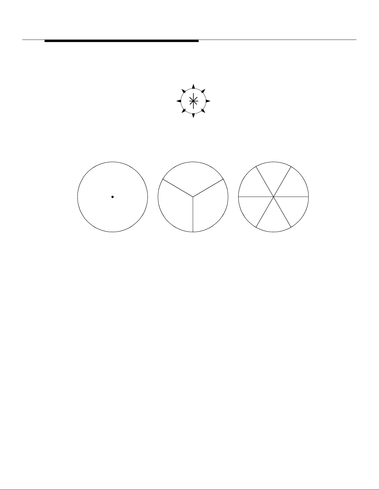
Antenna Hardware Configurations
NW
315
270
225
N
0
°45°
°
°
180
S
α
NE
°
90
°
EW
135
°
°
SESW
α
ζ
β
OMNI Directional
Antenna Configuration
ANT Face DE SG Greek Symbol
ALPHA
BETA
GAMMA
DELTA
EPSILON
ZETA
Figure 10-1. Series II Cell Site Antenna Configurations
βγ
ALL-Directional, 3-Sector
Antenna Configuration
α
β
γ
δ
ε
ζ
ε
δ
ALL-Directional, 6-Sector
Antenna Configuration
Sector Number
1
2
3
4
5
6
γ
10-4
Lucent Technologie s — Propriet ary
See notice on first page
401-660-100 Issue 11 August 2000
Page 84

Antenna Hardware Configurations
In addition to the two basic antenna ty pes li sted above, there is a new 2-branc h
intelligent antenna type. The 2-branch intelligent antenna will be the third type of
antenna discussed.
Fixed Antenna
Connection
Configuration
Shelves equipped for the fixed antenna connection option (see Figure 10-2) can
be used in frames where all the Radio Channel Units (RCUs) are co nnected to an
omni antenna or connected to directive antennas, or in frames that have some
RCUs connected to omni antennas and some connected to directive antennas.
On shelves with the fix ed antenna conne ction confi guration, po wer combi ners and
dividers interface 3 radio groups of 4 radios each.
For the transmit direction, the grouping on each shelf is by 4:1 RF power
combiners located on a BBN2 circuit board. The output of each combiner is
cabled to the Interconnection P anel Assembly where it is connected to 9:1 power
combiners for transmission to the LAFs. In this arrangement, the 9:1 combiners
can accommodate up to nine groups of four RCUs for a total of 36; they can also
handle up to seven antennas, which can be directive, omni, or a combination of
the two.
There is a test port on each 9:1 combiner through which the power level in each
channel signal can be measured with either a Radio Frequency (RF) power meter
having a tunabl e front end or a spectrum analyz er. The coupling loss between the
main output and the test port is 20 ± 0.5 dB.
For the Simulcast Setup feature with macrocell only (a macrocell is a Series II
antenna sector), the transmit path (see Figure 10-3) uses a 1:6 divider in Series
with a nominal 2-dB RF pad. The 1:6 divider is used to spli t the setup radio signals
to each sector antenna. The combined loss of the RF pad and 1:6 splitter is
almost the same as the loss of the 9:1 combiners that feed signals to the LA Cs.
The two setup radios used for Simulcast must be located in positions that are
each powered by a different power unit and served by the same shelf 4:1
combiner.
Lucent Technologie s — Propriet ary
See notice on first page
401-660-100 Issue 11 August 2000
10-5
Page 85
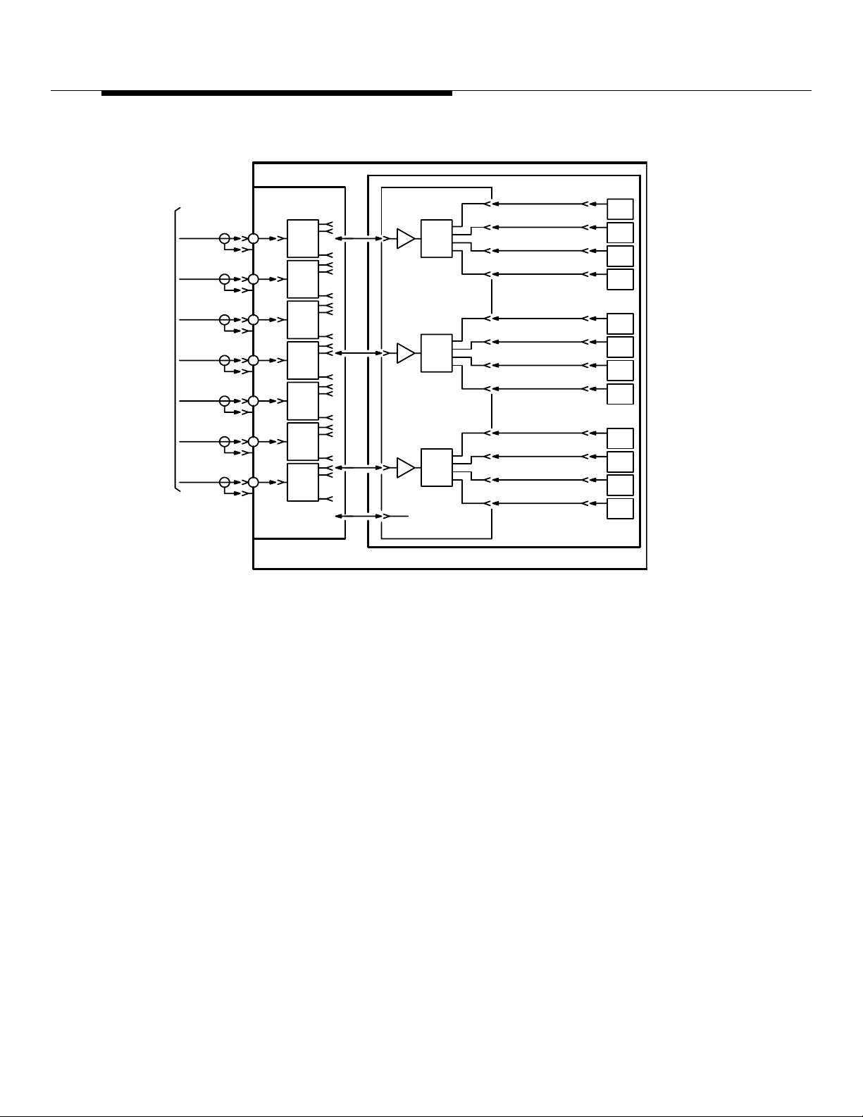
Antenna Hardware Configurations
ROM
NT
NTF
RAMES
Rx ANT "0"
(OMNI)
/
DIV 01
Rx ANT "1"
(ALPHA)
/DIV 01
Rx ANT "2"
(BETA)
/DIV 01
Rx ANT "3"
(GAMMA)
/DIV 01
Rx ANT "4"
(DELTA)
/DIV 01
Rx ANT "5"
(EPSILON)
/DIV 01
Rx ANT "6"
(ZETA)
/DIV 01
DIV 01 Rx RF SIG
/
1:9
RF PWR
DVDR
P/O
INTERCONNECTION
ASSEMBLY
PRIMARY/GROWTH
P/O
RCF
1:4
RF PWR
DVDR
NC
/
DIV 01 RF RCVR/DVDR
BOARD
DIV 01 Rx RF SIG/
DIV 01 Rx RF SIG/
/
DIV 01 Rx RF SIG
P/O
NON-SWITCHABLE
RCU SHELF
RCU
RCU
RCU
RCU
RCU
RCU
RCU
RCU
RCU
RCU
RCU
RCU
//0
1
2
3
4
5
6
7
8
9
10
11
A. FIXED ANTENNA CONNECTION
10-6
Figure 10-2. Interconnection Panel Assembly
Lucent Technologie s — Propriet ary
See notice on first page
401-660-100 Issue 11 August 2000
Page 86
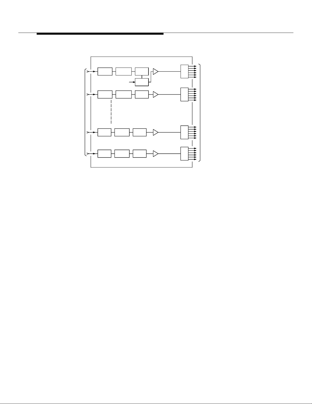
Antenna Hardware Configurations
OMNI RX-DIVERSITY 0
TEST
COUPLER
OMNI RX-DIVERSITY 1
BANDPASS
FILTER
CAL
SIG
NOTCH
FILTER
COUPLER
LOW-NOISE
PRE-AMPLIFIER
1:6
RF
SPLITTER
1:6
FROM
ANTENNAS
ALPHA
BETA
GAMMA
DELTA
EPSILON
ZETA RX-DIVERSITY 0
ZETA RX-DIVERSITY 1
P/O AIF
Figure 10-3. Antenna Interface
TO
RADIO
FRAME
SET
1:6
1:6
Lucent Technologie s — Propriet ary
See notice on first page
401-660-100 Issue 11 August 2000
10-7
Page 87
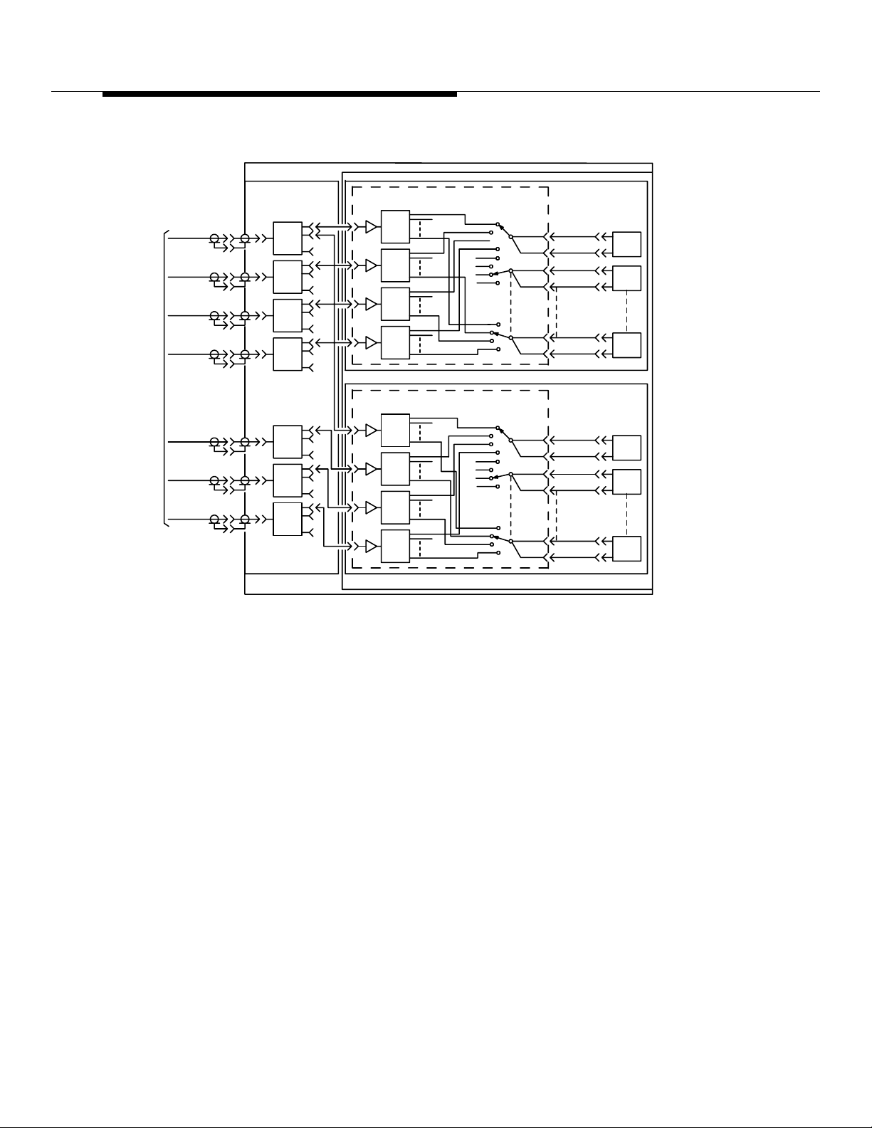
Antenna Hardware Configurations
ROM
NT
NTF
RAMES
ANT "0"
(OMNI)
DIV 0/1
RX SIG IN
ANT "1"
(ALPHA)
DIV 0/1
RX SIG IN
ANT "2"
(BETA)
DIV 0/1
RX SIG IN
ANT "3"
(GAMMA)
DIV 0/1
RX SIG IN
ANT "4"
(DELTA)
DIV 0/1
RX SIG IN
ANT "5"
(EPSILON)
DIV 0/1
RX SIG IN
ANT "6"
(ZETA)
DIV 0/1
RX SIG IN
P/O
INTERCONN
ASSEM
1:9
RF PWR
DVDR
1:9
RF PWR
DVDR
P/O
INTERCONNECTION
ASSEMBLY
DIV 0/1 RF RCVR AMPL/4X12 SWITCH/CMBR BOARD
1:12
RF PWR
DVDR
DIV 0/1 RF RCVR AMPL/4X12 SWITCH/CMBR BOARD
1:12
RF PWR
DVDR
P/O PRIMARY RCF
(B) SWITCHABLE ANTENNA CONNECTION
OMNI
ALPHA
BETA
GAMMA
OMNI
DELTA
EPSILON
ZETA
P/O DUAL-SHELF RCU ASSEMBLY
(RCU SWITCHABLE SHELF)
RX RF SIGSW-0
SW CONT SIG
SW-1 RX RF SIG
SW CONT SIG
SW-11
RX RF SIG
SW CONT SIG
(RCU SWITCHABLE SHELF)
SW-0
RX RF SIG
SW CONT SIG
RX RF SIGSW-1
SW CONT SIG
RX RF SIG
SW-11
SW CONT SIG
SHELF "1"
SHELF "2"
RCU
RCU
RCU
RCU
RCU
RCU
0
1
11
0
1
11
3-Sector Directive
Plus Omni
Antenna
Switching
Configuration
10-8
401-660-100 Issue 11 August 2000
Figure 10-4. Primary RCF Switch Antenna Connector
This description pertains to setup and locate radios only. In this configuration, the
switchable antenna connection opt ion i s used for the receive path (see
Figure 10-4). With the s witchab le antenna connection opt ion, each Radi o Channel
Unit (RCU) on the shelf can switch receive paths to any one of 4 available
antennas. Receive inputs from the AIFs are coupled through 1:9 RF power
dividers in the Interconnection Panel Assembly to 1:12 power dividers on a BBM1
circuit board on the RCU shelf. One board is used for each of the t wo diversities.
Each board has 12 single-pole , four-pos ition Radio Frequency (RF) switches.
Each switch is ass ociated with and controlled by an RCU.
The control lines to the switches in the two receive diversity paths associated with
the same RCU are connect ed in par all el and, therefore, controlled simultaneou sl y.
Fixed antenna connections are used in the transmit path.
Lucent Technologie s — Propriet ary
See notice on first page
Page 88

Antenna Hardware Configurations
6-Sector Directive
Plus Omni
Antenna
Switching with
Dual-Radio
Solution
3- or 6-Sector
Directional
Antenna
Switching with
Simulcast Setup
This description pertains to setup and locate r adios only. In this configu rati on (see
Figure 10-4), the hardwar e on the two shelves is the same as it is in the 3- sector
configuration; the differences are in the way the connections are made to the
AIFs. Fix ed antenna connections are used f or the transmit paths, and the
switchable antenna co nnection option is used for each of the two diversities in the
receive pat h s.
Inputs from the Omni antenna and directive antennas 1 through 6 are coupled
through 1:9 RF power dividers on the Interconnection Panel Assembly to BBM1
circuit boards on the Radio Channel Unit (RCU) shelves. One BBM is used for
each of the two dive rsities. The BBM1 boards on shelf 1 are connected to the
interface circuits of the Omni antenna and to directive antennas 1 through 3; the
boards on shelf 2 are connected to the Omni antenna and to directive antennas 4
through 6.
In this configurati on (see Figure 10-5), the hardwa re on the two shelves is the
same as it is in the omni setup 3- or 6-sector configurations; the difference is that
an omni antenna is not required f or the setup radios. For 3-sector conf igurations,
the “simulated omni” signal is connected fr om a 6:1 combine r in AIF0 to a
connector in the RCF Interconnection Panel Assembly an d thr ough a 2-dB pad to
the BBM1 board. For 4-, 5-, or 6-sector config uration s, the 2- dB pad is replaced b y
a 1:2 divider. The combination of a 6:1 combiner and 2-dB pad and a 6:1
combiner and 1:2 divider are roughly equivalent to the loss of the 1:9 divider they
replace. The simu lat ed omni signal is se nt t o the uppe r Switch ab le Radi o Shelf or,
through the 1:2 divider, to both the upper and lower Switchable Radio Shelves.
The 6:1 combiner output signal simulates the omnidirectional setup antenna
signal of an omnidirectional setup/directional voice Cell Site, thereby eliminating
the need for an omnidirectional antenna dedicated to the setup function.
AllOmnidirectional
Configuration
* The basic all-omnidirectional configuration described here requires omnidirectional setup. There are three setup
configuration options—omnidirectional setup, directional setup, and simulcast setup.
The basic all-omnidire ctional conf iguratio n (see Figure 10-6) consist s of one voi ce
channel transmit antenna, one optional setup transmit antenna to handle
transmission and paging si gnals over the entir e cell,
The receive antenn as feed all Cell Site voice channel radios, setup radios, and
analog locate radios.
In an all-omnidirectional configurat ion, up to seven voice channel transmit
antennas are possible via the multiple-LAC feature. The multiple-LAC feature
allows up to seven LACs and seven transmit antennas to be associated with one
antenna face. The maximum number of transmit antennas at a Series II Cell Site
is 7.
*
and two receive antennas.
Lucent Technologie s — Propriet ary
See notice on first page
401-660-100 Issue 11 August 2000
10-9
Page 89
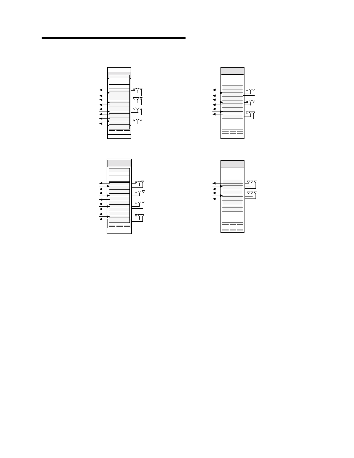
Antenna Hardware Configurations
.
PRIMARY—AIF0
RCF
LAC 0
RCF
RCF
LAC 1
RCF
RCF
LAC 2
RCF
RCF
LAC 3
RCF
PRIMARY—AIF0
RCF
LAC 0
RCF
RCF
LAC 1
RCF
RCF
LAC 2
RCF
RCF
LAC 3
RCF
GROWTH—AIF1
Ref Freq Gen
Rcvr Cal Gen
Radio Sw Panel
RX 0 RX 1TX
RX 0
0
RX
RX 0 RX 1TX
ANT 0
OMNI
RX 1TX
ANT 1
ALPHA
RX 1
TX
ANT 2
BETA
ANT 3
GAMMA
RCF
LAC 4
RCF
RCF
LAC 5
RCF
RCF
LAC 6
RCF
A. SERIES II Cell Site WITH OMNIDIRECTIONAL SETUP
GROWTH—AIF1
Ref Freq Gen
Rcvr Cal Gen
Rad Sw Panel
RX 0
TX
RX
RX 0 RX 1
TX
RX 0 RX 1TX
RX 0 RX 1TX
1
ANT 0
ALPHA
ANT 1
BETA
ANT 2
GAMMA
ANT 3 GAMMA
RCF
LAC 4
RCF
RCF
LAC 5
RCF
RX 0
RX 0
RX 0 RX 1TX
RX 0
RX 0 RX 1TX
RX 1TX
ANT 4
DELTA
RX 1
TX
ANT 5
EPSILON
ANT 6
ZETA
RX 1
TX
ANT 4
ANT 5
EPSILON
ZETA
All-Directional
Configuration
B. SERIES II Cell Site WITH DIRECTIONAL OR SIMULCAST SETUP
Figure 10-5. Mapping of Antenna Faces to Antenna Sets for the
Various Setup Options
In general, it will be necessary ultimately to sector omni cells to minimize
interference and provide increased system performance quality. Sectoring (see
Figure 10-5) is normally done with 120-degree directi onal antennas, where three
transmit antennas are used to cover the full 360 degrees. Sectoring may also be
done with 60-degree directional antennas, where six transmit antennas are used
to cov er the full 360 degrees .
Lucent Technologie s — Propriet ary
See notice on first page
10-10
401-660-100 Issue 11 August 2000
Page 90
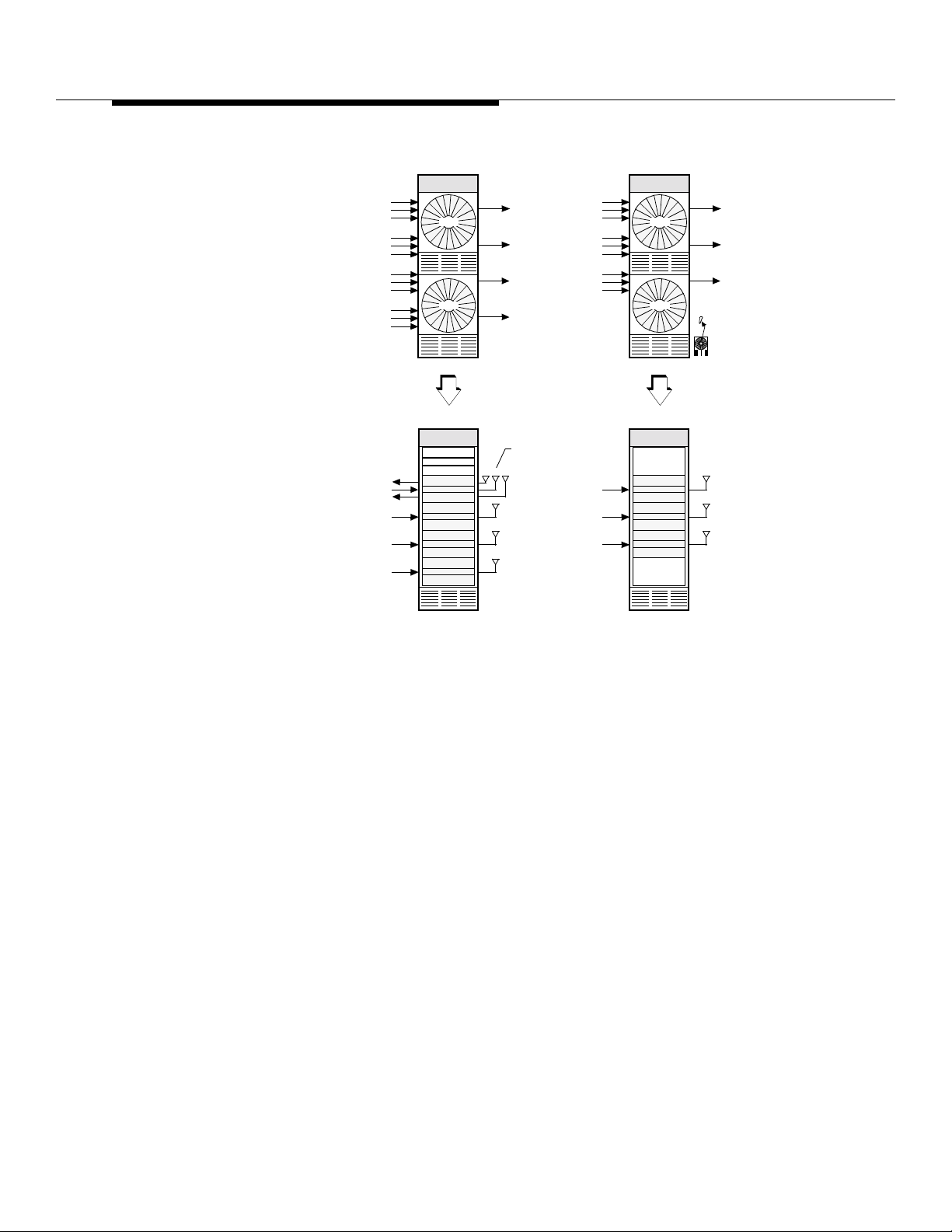
Antenna Hardware Configurations
Primary—LAF0
RCF0
RCF1
RCF2
RCF0
RCF1
RCF2
RCF0
RCF1
RCF2
RCF0
RCF1
RCF2
Primary—AIF0
RCF
LAC 0
RCF
LAC 1
LAC 2
LAC 3
LAC 2
LAC 0
Ref Freq Gen
Rcvr Cal Gen
Radio Sw Panel
LAC 3 OUT
LAC 2 OUT
LAC 1 OUT
LAC 0 OUT
RX 0RX 1TX
TX
TX
TX
VOICE T X
RCF0
AIF0
AIF0
AIF0
AIF0
RCF1
RCF2
RCF0
RCF1
RCF2
RCF0
RCF1
RCF2
Setup TX (Note)
ANT 0
OMNI
VOICE TX
VOICE TX
Growth—LAF1
Growth—AIF1
LAC 4
LAC 5
LAC 6
LAC 6
LAC 4
LAC 6 OUT
AIF1
LAC 5 OUT
AIF1
LAC 4 OUT
AIF1
Legend:
LAM
=
LAC
=
TX
VOICE TX
TX
VOICE TX
TX
VOICE TX
Setup TX May Also Carry Voice Channels.
Note:
Figure 10-6. Omnidirectional Cell Site Having Seven Transmit Antennas
The basic all-directional configuration consists of:
1. Three sets of 3-sector (120-degree) directional antennas or six set s of 6sector (60-degree) directional antennas,
2. One optional omnidirectional setup transmit antenna to handle
transmission and paging signals over the entire cell, and
3. Two optional omnidi rectional setup receive antennas. Each physical
antenna face has one or two directional transmit antennas and two
directional receive antennas.
Thus, when a cell is sectored, there are at least nine 120-degree directional
antennas or 18 60-degree directional antennas, plu s the opt ional three
omnidirectional setup antennas to complete the configuration—for a maximum of
21 antennas at a Series II Cell Site.
Lucent Technologie s — Propriet ary
See notice on first page
401-660-100 Issue 11 August 2000
10-11
Page 91

Antenna Hardware Configurations
If duplexers are used on each antenna face, the maxi mum number of antennas is
reduced to 14. A duplexer is a combined receive and transmit filter panel that
connects to a single antenna. Functionally, the receive and transmit circuits are
the same as the separate receive and transmit filter panels, exce pt that the
duplexer provides a combined receive/transmit antenna port. Thus, the duplexer
permits multiplexing of one of the receive paths—usually div ersity 0—with the
transmit path of an antenna face, thereb y reducing the required number of
antennas from three to two per face.
A 3-sector cell has three physical antenna faces, which are functionally
designated alpha, beta, and gamma. Usually, the antenna face whose center line
is pointing north is called alpha. The antenna face clockwise from alpha is call ed
beta, and the antenna face clockwise from beta is called gamma.
A 6-sector cell has six physical antenna faces, which are functionally designated
alpha, beta, gamma, delta, epsilon, and zeta. The antenna face clockwise from
gamma is called delta, the antenna f ace clockwise from delta is cal led epsilon,
and the antenna face clockwise from epsilon is called zeta.
Figure 10-1 shows how the antenna faces map to antenna sets for the
omnidirectional, directional, and simulcast set up opti ons. Notice that antenna 0
does not necessarily mean antenna omni; antenna 0 may also mean antenna
alpha—at a Cell Site having directional or simulcast setup.
The Cell Site RCC identifies the transmit and receiv e anten nas associated with an
antenna face by the Radio Test Unit Switch Pa nel ( RSP) switch positions used to
test them. The RSP cable connections to transmi t antennas 0 through 6 are fixed,
but the RSP cable connecti ons to recei v e antenn as 0 through 6 f or div er sity 0 and
diversity 1 are not fixed and depend upon whether antenna 0 means antenna
omni or antenna alpha. The RSP cable connections at a Series II Cell Site when
antenna 0 means antenna omni (applicable to Cell Sites having omnid ir ectional
setup). The RSP cable connections at a Series II Cell Site when antenna 0 means
antenna alpha (applicable to Cell Sites having).
10-12
Lucent Technologie s — Propriet ary
See notice on first page
401-660-100 Issue 11 August 2000
Page 92

Antenna Hardware Configurations
Radio Tr ansmission and Reception
The Cell Site receives digital-voice signals via a T1 line, modulates and upconv erts the signals to RF, and then transmits the RF output signals over the air
interf ace to a mobil e station. In the mobile-tr ansmit dir ection, the Cel l Site r eceiv es
RF input signals from a mobile station via the receive antennas (two inputs for
diversity), then filters, amplifies, and recovers the origin al mobi le data for
transmission over a T1 line to the MSC.
Two-branch spatial diversit y on reception is achieved by providing two receive
antennas ph ysically separated b y about 3 to 4 meters so that their received
signals are not correl ated. When one ant enna r eceives a multipath fade, the other
antenna probably will not.
RF Transmitter
Interfaces
There are two distinct RF tr ansmitter interface configurations: the allomnidirectional antenna configuration and the all-directional (120- or 60-degree)
antenna configuration. The RF output can be transmitted through an omnitransmit antenna or throu gh a tr ansmit antenna on one of the physical ant enna
faces of the directional antennas. The low-power RF trans missions from multiple
radios are combined and amplified b y a LAC and sent through a transmit fi lt er
panel to the transmit antenna (see Figure 10-7).
Lucent Technologie s — Propriet ary
See notice on first page
401-660-100 Issue 11 August 2000
10-13
Page 93
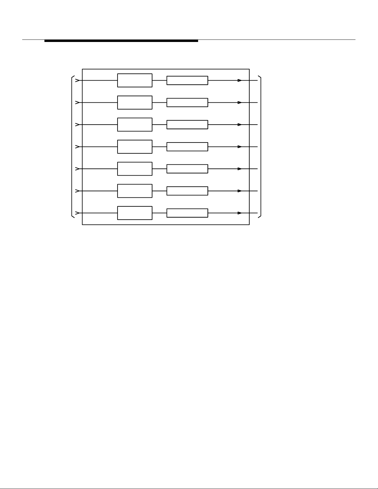
Antenna Hardware Configurations
ROM
AF
TX BANDPASS
FILTER
TEST COUPLER
P/O AIF
Figure 10-7. Antenna Coupler
Tx"0"
Tx"1"
Tx"2"
Tx"3"
Tx"4"
Tx"5"
Tx"6"
TO TX
ANTENNAS
RF Receiver
Interfaces
2 Branch
Intelligent
Antenn a, Feature
IDentification
(FID) #3145
There are two dist inct RF receiver interface configurations: the all-omnidirecti onal
antenna configuration and the all-directional (120- and 60-degree) antenna
configuration. The RF input can be received through a pair of omni-receiv e
antennas or through a pair of receive antennas on one of the physical antenna
faces of the di rectional antennas. Th e RF input signals pass through receive filter
panels to RF power dividers, where the signals are divided and cabled to the
diversity 0 and diversity 1 receiver sections (identical receivers) of the radios.
What “2 Branch ” means in 2 Branch Intelligent Antennas
This chapter covers the “2 Branch Intelligent Antennas” feature, which has
Feature IDentification (FID) #3145. The “2 Branch Intelligent Antennas” feature
was developed to deliver better voice quality on the transmission link bet ween the
mobile and the base station. “2 branch” refers to the 2 existing paths, 1 path from
each of the 2 diversity receive antennas, to the Enhanced Digital Radio Unit’s
(EDRU) or the Dual Radio Module (DRM). While a fo ur branc h rev ers e link system
would have yielded a greater improvement in voice quality, it would have required
extens ive redesign of the existing Series II architecture. Therefore, the 2 branch
system, which required no red esign, was implemented.
Lucent Technologie s — Propriet ary
See notice on first page
10-14
401-660-100 Issue 11 August 2000
Page 94

Antenna Hardware Configurations
How the Enhanced Digital Radio Unit (EDRU) is used to support 2
Branch Intellig ent Ante nna s
The 2 Branch Intelligent Antennas feat ure is implemented i n the Enhanced Digital
Radio Unit’s (EDRU’s) software. However, the 2 Branch Intelligent Antennas
Feature does not add a new Non-Volatile Memory (NVM) image. Both of the
existing Enhanced Digital Radio Unit’s (EDRU’s) Non-Volatile Memory (NVM)
images (packet pipe & non-packet pipe) incorporate the new software. The
Enhanced Digital Radio Unit’s (EDRU) is used in the Series II Classic, Series IIe,
Series IIm, Series IImm, and PCS TDMA Minicell products. The 2 Branch
Intelligent Antennas Feature is not intended for and does not work with Lucent’s
analog products. No extra Radio Frequency (RF) hardware is required to
implement this feature and it does not impact the existing base station’s Radio
Frequency (RF) footprint, antennas, size, or power.
What “Intelligent” means in 2 Branch Intelligent Antennas
“Intelligent Antenna s” refers to an entire system co mprised o f a radi ating st ructure
with antennas for transmit and receiv e, which ar e connected via Radio Frequency
(RF) cables to a Digital Signal Processor (DSP) (within the Enhanced Digital
Radio Unit’s (EDRU) which has the ability to execute intelligent algorithms that
process the Radio Frequency (RF) signals to i mp rove system performance.
The Adapti v e
Interference
Rejection
Techniqu e
The 2 Branch Intelligent Antennas Feature uses the “Adaptive Interference
Rejection,” technique, als o know n as digi tal be amf orming, for optimally combining
the 2 diversity receive antennas. Adaptive Inter ference Rejection captures the
Radio Frequency (RF) signals from the antenna elements and converting them
into 2 streams of binary I and Q signals, which together represent the amplitudes
and phases of the signals received by the antenna. The adaptive interf erence
rejection is carried out by weighting these digital signals, thereby adjusting their
amplitudes and phases, such t hat when the y ar e added toget her, it maximizes the
Signal-to-Noise Ratio (SINR) for the desired signal. A typical digital adaptive
interference rejection system consists of an array of antenna elements,
independent receivers for the individual antenna elements, and one or more
digital signal processors. This feature is a software enhancement only and
makes use of the existing 2 branch arc hitecture f or receive diversity built into the
Enhanced Digital Radio Unit’s (EDRU). This feature wo rks for only the reverse
link in the Enhanced Digital Radio Unit’s (EDRU). All processing is done at
baseband.
Performance with 2 Bra nch In tel ligent Antennas
The 2 Branch Intelligent Antennas Feature provides better voice quality in an
interference dominated environment on the reverse link (Mobile to Base Station)
only. The 2 Branch Intelligent Antennas feature yields a 3 dB performance
enhancement in the re verse link C/I in an interference limit ed environment when
compared to the exi sti ng maximal ratio combining techniqu e used in the
Lucent Technologie s — Propriet ary
See notice on first page
401-660-100 Issue 11 August 2000
10-15
Page 95

Antenna Hardware Configurations
differ ential detection and trellis equalization paths. On average, co-chann el
interference is expe cted to decrease by a nominal 3 dB compared to the classic
diversit y scheme in the Enhanced Digital Radio Unit’s (EDRU) in an interference
limited environment. The level of improvement depends on the distribution of cochannel users in neighboring cells. This feature allows each 30 kHz TDMA
channel, through software processing, to redu ce/eliminate the effects of cochannel interference within the field of view of the Enhanced Digital Radio Unit’s
(EDRU). Baseband processing is able to combine the spatially separated
diversities for interference rejection.
The 2 Branch Intelligent Antennas F ea ture equal s the performance of the existin g
maximal ratio combining t echnique when used i n a noise limite d envir onment. The
feature does not increase the existing capacity or range of the base st ati on in a
noise limited envi ronment. A tower top Low Noise Amplifi er (LNA), however,
provides r ange e xt ension o n the re verse link in a noise limited envir onment. Using
this feat ure together with a tower top Low Noise Amplifier (LNA) would yield
interference rejection and range extension on the reverse link. However, the
purpose of this feature is to improve voice quality in an interference l imi ted
environment, not a noise limited environment. Activation of this feature does not
degrade the existing performance of the Enhanced Di gital Radi o Unit’s (EDRU) in
a noise limited environment .
Digital Locate under 2 Branch Intelligent Antennas 0
The 2 Branch Intelligent Antennas Feature should not be implemented on the
digital locate rad io. Locate radios are used to determine if a call will be placed on
a certain channel. Selection criteria should be based on the best channel in a
noise limited environment. Calls should not be placed on channels with a lot of
interference.
2 Branch Intelligent Antennas Testing 0
Testing of the 2 Branch Intelligent Antennas on the Enhanced Digital Radio Unit’s
(EDRU) feature is done in maximal ratio combining mode. Current testing in the
Enhanced Digital Radio Unit’s (EDRU) only tests one branch of the dual diversity
receive pat hs at a time. To eliminate the development of a ne w testi ng routine wi th
minimal gains, the Enhanced Digital Radio Unit’s (EDRU) should be swi tched
back to maximal ratio combining mode and tested one branch at a time.
2 Branch Intelligent Antennas Phased Release
The 2 Branch Intelligent Antennas Feature is a phased release. Phase 1
implements this feature on the digital traffi c radio and incorporates the adaptive
interference rejection techni que into the differ ential detection path of the Digital
Signal Processor (DSP).
10-16
Lucent Technologie s — Propriet ary
See notice on first page
401-660-100 Issue 11 August 2000
Page 96

Antenna Hardware Configurations
2 Branch Intelligent Antennas Feature Activation 0
The 2 Branch Intelligent Antennas Feature is activated on a per Cell Site Feature
Activation Fil e wit h Quali fiers (QFAF) basis. The feature is enab led f rom the
Mobile Switching Center (MSC) by a translation to select adaptive interference
mode or maximal ratio combining mode on a cell by cell basis. All Enhanced
Digital Radio Unit’s (EDRUs) at the cell site have the feature turned on or off on a
cell by cell basis using RC/V.
Lucent Technologie s — Propriet ary
See notice on first page
401-660-100 Issue 11 August 2000
10-17
Page 97

Lucent Technologie s — Propriet ary
See notice on first page
10-18
401-660-100 Issue 11 August 2000
Page 98

Cell Site Hardware Functions and
Interconnections
Contents
Contents 11-1
■
Introduction 11-5
■
Radio Control Complex (RCC) 11-5
Digital Signal (DS1) Units 11-6
Digital Facilitie s Int e rface (D F I) Units 11-6
Clock And Tone (CAT) Units 11-7
Radio Fram e Set 11-7
RCF Architecture and Bus Structure 11-9
System bus 11-9
Update bus 11-9
TDM b uses 11-9
Data Link and Voice
■
Path Connections11-14
T1/E1 Communications 11-14
T1 Line Interface 11-16
E1 Line Interface 11-16
Line Interf ace Connections at the Cell 11-17
■
Data Link Configurations 11-21
■
One DS1/DFI Unit and One Data Link 11-21
11
Lucent Technologie s — Propriet ary
See notice on first page
401-660-100 Issue 11 August 2000
11-1
Page 99

Cell Site Hardware Functi ons and Int erconnections
One DS1/DFI Unit and Two Data Links 11-21
Two DS1/DFI Units and Two Data Links 11-21
Remote Data Link Reconfiguration 11-21
Exter n a l In te rfaces to the Ser i e s II Cell Site 11-22
■
Voice Trunks from the Digital Cellular Switch (DCS) 11-22
Time Division Multiplexed Buses 1 1-22
TDM Bus Operation 11-22
TDM Bus Addresses 11-24
TDM Bus Communications: the Archangel/Angel Concept 11- 26
■
Angel 11-27
Archangel 11-27
Sanity And Control Interface 11-28
■
NPE and SNPE 11-31
■
Synchronization of the Cell Site to the MSC 11-32
■
TDMCKSEL 11-36
TDMCKFAIL 11-36
TDMCLK 11-36
TDMFR 11-36
TDMSYNC1 11-36
TDMSYNC2 11-36
Mobile Switching Center (MSC) to Cell Site Communicatio ns 11-37
■
DS1, DFI, and CAT Circuit Descriptions 11-38
■
DS1 (TN171) Circuit Description 11-38
DFI (TN3500) Circuit Description 11-38
DFI (TN1713B) Circuit Operation 11-40
DFI Initialization Message for T1 Operation 11-4 2
■
D4 or E SF Fram in g 11-42
ZCS or B8ZS Line Format 11-46
Line-length Compensation Setting 11-46
Enable or Disable On-demand LLB or BLB Control 11-46
Select Synchronization Reference 11-47
Specify Idle Code 11-47
DFI Initialization Message for E1 Operation 11-48
■
CEPT Fra ming with or wit hout CRC-4 Error Checking 11-48
CCS or CAS Signaling Mode 11-48
HDB3 or Transparent Line Format 11-50
11-2
Lucent Technologie s — Propriet ary
See notice on first page
401-660-100 Issue 11 August 2000
Page 100

Cell Site Hardware Functi ons and Int erconnections
Enable or Disabl e On-demand LLB or BLB Control 11-50
Select Synchronization Reference 11-50
Select Idle Cod e 11-50
DFI Network-Update Talk Message 11 -50
DFI Network-Update Listen Message 11-50
DFI Status Indicators 11-51
■
Red LED 11-51
Yellow LED 11-51
Green LED 11-51
CAT (TN170) Circuit Description 11-52
■
Bus Clock Generation and Monitoring for the TDM Bus 11-55
■
Maintenance Tone Generation 11-56
■
Maintenance Tone Detection and Measurement 11-57
CAT Status Indicators 11 -58
■
Red LED 11-58
Green LED 11-58
Automati c R e c overy Actio ns 11-59
■
Hardware Error Handling Stra tegy 11-6 0
■
Immediate Action 11-60
All Tests Pass (ATP) Analysis 11-60
Single Time-period Analysis 11-60
Fai l/Pass Anal ysis 11-60
Leaky Bucket Analysis 11-61
RCC Hardware Errors and Recovery Actions 11 -62
■
DS1/DFI Hardware Errors and Recovery Actions 11-63
■
DS1/DFI and T1 Errors—Detailed Description 11-64
■
Loss Of Signal (LOS) 11-64
Blue Alarm 11-64
Red Alarm 11-64
Major Alarm 11-65
Yellow Alarm 11-65
Fan Alarms 11-66
■
Preamp Fan 11-66
LineariZeR Fan Procedure 11-66
Major Alarm 11-66
Minor Alarm 11-67
Lucent Technologie s — Propriet ary
See notice on first page
401-660-100 Issue 11 August 2000
11-3
 Loading...