

Page 1

Cellular Networks
FCC ID: IHET7HM1
2.5GHz MOTOwi4™ 25600 Diversity Access Point
APPLICANT: MOTOROLA
Users Manual Exhibit
FCC Filing – WAP25600 MOTOwi4
TM
Diversity Access Point @ 2.5GHz 1 of 1
Page 2

Ground Based Access Point (GAP)
Hardware Installation
68P09286A73 -1 JUL 2007
PRELIMINARY - UNDER DEVELOPMENT
© 2006 Motorola, Inc. All Rights R eserv ed
Page 3

Accuracy
While reasonable efforts have been made to assure the accuracy of this document, Motorola, Inc. assumes no
liability resulting from any inaccuracies or omissions in this document, or from use of the information obtained
herein. Motorola, Inc. reserves the right to make changes to any products described herein to improve reliability ,
function, or design, and reserves the right to revise this document and to make changes from time to time in content
hereof with no obligation to notify any person of revisions or changes. Motorola, Inc. does not assume any liability
arising out of the application or use of any product, software, or circuit described herein; neither does it convey
license under its patent rights or the rights of others. It is possible that this publication may contain references to, or
information about Motorola products (machines and programs), programming, or services that are not announced
in your country . Such references or information must not be construed to mean that Motorola intends to announce
such Motorola products, programming, or services in your country .
Copyrights
This document, Motorola products, and 3rd P arty Software products described in this document may include
or describe copyrighted Motorola and other 3rd P arty supplied computer programs stored in semiconductor
memories or other media. Laws in the United States and other countries preserve for Motorola, its licensors, and
other 3rd P arty supplied software certain exclusive rights for copyrighted material, including the exclusive right
to copy , reproduce in any form, distribute and make derivative works of the copyrighted material. Accordingly ,
any copyrighted material of Motorola, its licensors, or the 3rd P arty software supplied material contained in the
Motorola products described in this document may not be copied, reproduced, reverse engineered, distributed,
merged or modified in any manner without the express written permission of Motorola. Furthermore, the purchase
of Motorola products shall not be deemed to grant either directly or by implication, estoppel, or otherwise, any
license under the copyrights, patents or patent applications of Motorola or other 3rd P arty supplied software,
except for the normal non-exclusive, royalty free license to use that arises by operation of law in the sale of a
product.
A list of 3rd P arty supplied software copyrights are contained in the Supplemental information section of this
document.
Restrictions
Software and documentation are copyrighted materials. Making unauthorized copies is prohibited by law . No part
of the software or documentation may be reproduced, transmitted, transcribed, stored in a retrieval system, or
translated into any language or computer language, in any form or by any means, without prior written permission
of Motorola, Inc.
License Agreements
The software described in this document is the property of Motorola, Inc and its licensors. It is furnished by express
license agreement only and may be used only in accordance with the terms of such an agreement.
High Risk Materials
Components, units, or 3rd P arty products used in the product described herein are NOT fault-tolerant and are NOT
designed, manufactured, or intended for use as on-line control equipment in the following hazardous environments
requiring fail-safe controls: the operation of Nuclear F acilities, Aircraft Navigation or Aircraft Communication
Systems, Air Traffic Control, Life Support, or W eapons Systems (High Risk Activities). Motorola and its supplier(s)
specifically disclaim any expressed or implied warranty of fitness for such High Risk Activities.
T rademarks
Motorola and the Stylized M Logo are registered in the US P atent & Trademark Office. All other product or service
names are the property of their respective owners.
The CE mark confirms Motorola, Inc. statement of compliance with EU directives applicable to this product. Copies
of the Declaration of Compliance and installation information in accordance with the requirements of EN50385 can
be obtained from the local Motorola representative or by contacting the Customer Network Resolution Center
(CNRC). The 24 hour telephone numbers are listed at h t t p s : / / m y n e t w o r k s u p p o r t . m o t o r o l a . c o m . Select Customer
Network Resolution Center contact information. Alternatively if you do not have access to CNRC or the
internet, contact the Local Motorola Office.
PRELIMINARY - UNDER DEVELOPMENT JUL 2007
Page 4

T a b l e
o f
C o n t e n t s
Contents
■ ■ ■ ■ ■ ■ ■ ■ ■ ■ ■ ■ ■ ■ ■ ■ ■ ■ ■ ■ ■ ■ ■ ■ ■ ■ ■ ■ ■ ■ ■ ■ ■ ■ ■ ■ ■ ■ ■ ■ ■ ■ ■ ■ ■ ■ ■ ■ ■ ■ ■ ■ ■ ■ ■ ■ ■ ■ ■ ■ ■ ■
Ground Based Access Point (GAP) Hardware Installation
Revision history . . . . . . . . . . . . . . . . . . . . . . . . . . . . . . . . . . . . . . . . . 2
V ersion information . . . . . . . . . . . . . . . . . . . . . . . . . . . . . . . . . . . . . 2
Resolution of Service Requests . . . . . . . . . . . . . . . . . . . . . . . . . . . . . . . 2
Incorporation of Change Notices . . . . . . . . . . . . . . . . . . . . . . . . . . . . . . . 2
General information . . . . . . . . . . . . . . . . . . . . . . . . . . . . . . . . . . . . . . . 3
Purpose . . . . . . . . . . . . . . . . . . . . . . . . . . . . . . . . . . . . . . . . . . . 3
Cross references . . . . . . . . . . . . . . . . . . . . . . . . . . . . . . . . . . . . . . . 3
T ext conventions . . . . . . . . . . . . . . . . . . . . . . . . . . . . . . . . . . . . . . . 4
Contacting Motorola . . . . . . . . . . . . . . . . . . . . . . . . . . . . . . . . . . . . . . . 5
24–hour support . . . . . . . . . . . . . . . . . . . . . . . . . . . . . . . . . . . . . . . 5
Questions and comments . . . . . . . . . . . . . . . . . . . . . . . . . . . . . . . . . . 5
Errors . . . . . . . . . . . . . . . . . . . . . . . . . . . . . . . . . . . . . . . . . . . . 5
Security advice . . . . . . . . . . . . . . . . . . . . . . . . . . . . . . . . . . . . . . . . . . 6
W arnings, cautions, and notes . . . . . . . . . . . . . . . . . . . . . . . . . . . . . . . . . . 7
W arnings . . . . . . . . . . . . . . . . . . . . . . . . . . . . . . . . . . . . . . . . . . . 7
Cautions . . . . . . . . . . . . . . . . . . . . . . . . . . . . . . . . . . . . . . . . . . . 7
Notes . . . . . . . . . . . . . . . . . . . . . . . . . . . . . . . . . . . . . . . . . . . . 7
Safety . . . . . . . . . . . . . . . . . . . . . . . . . . . . . . . . . . . . . . . . . . . . . . 8
General safety . . . . . . . . . . . . . . . . . . . . . . . . . . . . . . . . . . . . . . . . 8
Electromagnetic energy . . . . . . . . . . . . . . . . . . . . . . . . . . . . . . . . . . . 8
Caring for the environment . . . . . . . . . . . . . . . . . . . . . . . . . . . . . . . . . . . 9
In EU countries . . . . . . . . . . . . . . . . . . . . . . . . . . . . . . . . . . . . . . . 9
In non -EU countries . . . . . . . . . . . . . . . . . . . . . . . . . . . . . . . . . . . . . 9
CMM labeling and disclosure table . . . . . . . . . . . . . . . . . . . . . . . . . . . . . . . 10
Motorola document set . . . . . . . . . . . . . . . . . . . . . . . . . . . . . . . . . . . . . 11
Ordering documents and CD -ROMs . . . . . . . . . . . . . . . . . . . . . . . . . . . . . 11
Document banner definitions . . . . . . . . . . . . . . . . . . . . . . . . . . . . . . . . 11
Data encryption . . . . . . . . . . . . . . . . . . . . . . . . . . . . . . . . . . . . . . . 11
Supplemental information . . . . . . . . . . . . . . . . . . . . . . . . . . . . . . . . . . . . 12
Third party computer software and trademarks . . . . . . . . . . . . . . . . . . . . . . . 12
FCC requirements . . . . . . . . . . . . . . . . . . . . . . . . . . . . . . . . . . . . . . . . 13
Content . . . . . . . . . . . . . . . . . . . . . . . . . . . . . . . . . . . . . . . . . . . 13
R adio frequency exposure . . . . . . . . . . . . . . . . . . . . . . . . . . . . . . . . . . 13
FCC P art 15 requirements . . . . . . . . . . . . . . . . . . . . . . . . . . . . . . . . . . 13
■
■
■
■
Chapter 1: Overview
Introduction . . . . . . . . . . . . . . . . . . . . . . . . . . . . . . . . . . . . . . . . . . . 1 - 2
Product Description . . . . . . . . . . . . . . . . . . . . . . . . . . . . . . . . . . . . . . . 1 - 3
Manual Order . . . . . . . . . . . . . . . . . . . . . . . . . . . . . . . . . . . . . . . . . . 1 - 4
Recommended Documents . . . . . . . . . . . . . . . . . . . . . . . . . . . . . . . . . . . . 1 - 5
Abbreviations and Acronyms . . . . . . . . . . . . . . . . . . . . . . . . . . . . . . . . . . . 1 - 6
68P09286A73 -1 i
JUL 2007 PRELIMINARY - UNDER DEVELOPMENT
Page 5

Contents
T ools and Materials . . . . . . . . . . . . . . . . . . . . . . . . . . . . . . . . . . . . . . . 1 - 7
Introduction . . . . . . . . . . . . . . . . . . . . . . . . . . . . . . . . . . . . . . . . . 1 - 7
T ools and Materials . . . . . . . . . . . . . . . . . . . . . . . . . . . . . . . . . . . . . 1 - 7
Chapter 2: Site Preparation
General . . . . . . . . . . . . . . . . . . . . . . . . . . . . . . . . . . . . . . . . . . . . . 2 - 2
Overview . . . . . . . . . . . . . . . . . . . . . . . . . . . . . . . . . . . . . . . . . . . 2 - 2
Indoor and outdoor sites . . . . . . . . . . . . . . . . . . . . . . . . . . . . . . . . . . . 2 - 2
Site Preparation Overview . . . . . . . . . . . . . . . . . . . . . . . . . . . . . . . . . . . . 2 - 3
Installation . . . . . . . . . . . . . . . . . . . . . . . . . . . . . . . . . . . . . . . . . . 2 - 3
Site Manager . . . . . . . . . . . . . . . . . . . . . . . . . . . . . . . . . . . . . . . . 2 - 3
V erification and Procedures . . . . . . . . . . . . . . . . . . . . . . . . . . . . . . . . . 2 - 3
Initial site inspection . . . . . . . . . . . . . . . . . . . . . . . . . . . . . . . . . . . . . . . 2 - 4
Indoor intial site inspection . . . . . . . . . . . . . . . . . . . . . . . . . . . . . . . . . 2 - 4
Outdoor initial site inspection . . . . . . . . . . . . . . . . . . . . . . . . . . . . . . . . 2 - 4
Prepare Site for Equipment Arrival . . . . . . . . . . . . . . . . . . . . . . . . . . . . . . . 2 - 6
Description . . . . . . . . . . . . . . . . . . . . . . . . . . . . . . . . . . . . . . . . . 2 - 6
Equipment Arrival . . . . . . . . . . . . . . . . . . . . . . . . . . . . . . . . . . . . . . 2 - 6
Procedure to prepare the site for the equipment . . . . . . . . . . . . . . . . . . . . . . . 2 - 6
Site layout inspection . . . . . . . . . . . . . . . . . . . . . . . . . . . . . . . . . . . . . . 2 - 8
Shipping and Handling . . . . . . . . . . . . . . . . . . . . . . . . . . . . . . . . . . . . . . 2 - 9
Overview . . . . . . . . . . . . . . . . . . . . . . . . . . . . . . . . . . . . . . . . . . . 2 - 9
How Equipment is Shipped . . . . . . . . . . . . . . . . . . . . . . . . . . . . . . . . . 2 - 9
How Equipment Arrives . . . . . . . . . . . . . . . . . . . . . . . . . . . . . . . . . . . 2 - 10
Recommended Unpacking T ools . . . . . . . . . . . . . . . . . . . . . . . . . . . . . . . 2 - 10
Unpacking . . . . . . . . . . . . . . . . . . . . . . . . . . . . . . . . . . . . . . . . . . . . 2 - 11
GAP equipment . . . . . . . . . . . . . . . . . . . . . . . . . . . . . . . . . . . . . . . 2 - 11
Outdoor GAP . . . . . . . . . . . . . . . . . . . . . . . . . . . . . . . . . . . . . . . . . 2 - 11
Unpacking procedure . . . . . . . . . . . . . . . . . . . . . . . . . . . . . . . . . . . . 2 - 12
Indoor GAP . . . . . . . . . . . . . . . . . . . . . . . . . . . . . . . . . . . . . . . . . 2 - 13
Unpacking procedure . . . . . . . . . . . . . . . . . . . . . . . . . . . . . . . . . . . . 2 - 13
Chapter 3: Cable Descriptions
Overview . . . . . . . . . . . . . . . . . . . . . . . . . . . . . . . . . . . . . . . . . . . . . 3 - 2
Configurations Supported . . . . . . . . . . . . . . . . . . . . . . . . . . . . . . . . . . . . 3 - 3
Cable Installation Order . . . . . . . . . . . . . . . . . . . . . . . . . . . . . . . . . . . . . 3 - 4
Cable Descriptions and P art Numbers . . . . . . . . . . . . . . . . . . . . . . . . . . . . . . 3 - 5
Cable Lengths . . . . . . . . . . . . . . . . . . . . . . . . . . . . . . . . . . . . . . . . . . 3 - 7
Chapter 4: Indoor GAP Hardware Installation
Indoor (rack - mount) GAP installation . . . . . . . . . . . . . . . . . . . . . . . . . . . . . . 4 - 2
GAP rack - mount cages . . . . . . . . . . . . . . . . . . . . . . . . . . . . . . . . . . . 4 - 2
Indoor GAP product identification . . . . . . . . . . . . . . . . . . . . . . . . . . . . . . . . 4 - 3
B CU Cage and components . . . . . . . . . . . . . . . . . . . . . . . . . . . . . . . . . 4 - 3
TRX cage and components . . . . . . . . . . . . . . . . . . . . . . . . . . . . . . . . . . 4 - 3
R ack mounting configuration . . . . . . . . . . . . . . . . . . . . . . . . . . . . . . . . . . 4 - 4
GAP rack mounting (typical) . . . . . . . . . . . . . . . . . . . . . . . . . . . . . . . . . 4 - 4
Mounting and bolt configurations . . . . . . . . . . . . . . . . . . . . . . . . . . . . . . . . 4 - 5
Mounting hardware . . . . . . . . . . . . . . . . . . . . . . . . . . . . . . . . . . . . . 4 - 5
Installation on concrete . . . . . . . . . . . . . . . . . . . . . . . . . . . . . . . . . . . 4 - 6
Installation on wooden floor . . . . . . . . . . . . . . . . . . . . . . . . . . . . . . . . . 4 - 6
Installation of GAP cages in the indoor rack . . . . . . . . . . . . . . . . . . . . . . . . . . . 4 - 8
B CU cage . . . . . . . . . . . . . . . . . . . . . . . . . . . . . . . . . . . . . . . . . . 4 - 8
TRX cage . . . . . . . . . . . . . . . . . . . . . . . . . . . . . . . . . . . . . . . . . . . 4 - 8
R ack cabling with cages installed . . . . . . . . . . . . . . . . . . . . . . . . . . . . . . . . 4 - 9
ii 68P09286A73 -1
PRELIMINARY - UNDER DEVELOPMENT JUL 2007
Page 6

Ground Based Access P oint (GAP) Hardw are Installation Contents
Cage to cage . . . . . . . . . . . . . . . . . . . . . . . . . . . . . . . . . . . . . . . . . 4 - 9
External cabling to rack . . . . . . . . . . . . . . . . . . . . . . . . . . . . . . . . . . . 4 - 9
Chapter 5: Outdoor GAP Hardware Installation
Outdoor (cabinet - mount) GAP installation . . . . . . . . . . . . . . . . . . . . . . . . . . . 5 - 2
GAP cabinets . . . . . . . . . . . . . . . . . . . . . . . . . . . . . . . . . . . . . . . . . 5 - 2
Outdoor GAP product identification and configurations . . . . . . . . . . . . . . . . . . . . . 5 - 3
Common outdoor mounting information . . . . . . . . . . . . . . . . . . . . . . . . . . . 5 - 3
Stacked GAP cabinet configuration . . . . . . . . . . . . . . . . . . . . . . . . . . . . . 5 - 3
Side - by - side GAP cabinet configuration . . . . . . . . . . . . . . . . . . . . . . . . . . 5 - 3
GAP concrete slab mounting . . . . . . . . . . . . . . . . . . . . . . . . . . . . . . . . . . . 5 - 4
Installation Planning . . . . . . . . . . . . . . . . . . . . . . . . . . . . . . . . . . . . . 5 - 4
Concrete slab configurations . . . . . . . . . . . . . . . . . . . . . . . . . . . . . . . . . 5 - 4
Cabinet mounting . . . . . . . . . . . . . . . . . . . . . . . . . . . . . . . . . . . . . . 5 - 6
Conduit routed through back of BTS cabinet . . . . . . . . . . . . . . . . . . . . . . . . . 5 - 7
Conduit routed through bottom of BTS cabinet . . . . . . . . . . . . . . . . . . . . . . . 5 - 8
I -beam support . . . . . . . . . . . . . . . . . . . . . . . . . . . . . . . . . . . . . . . . 5 - 9
Outdoor mounting and bolt configurations . . . . . . . . . . . . . . . . . . . . . . . . . . . . 5 - 11
Concrete pad installation and ground system . . . . . . . . . . . . . . . . . . . . . . . . . . 5 - 12
Materials needed . . . . . . . . . . . . . . . . . . . . . . . . . . . . . . . . . . . . . . 5 - 12
Ground system . . . . . . . . . . . . . . . . . . . . . . . . . . . . . . . . . . . . . . . . 5 - 12
Conduit routing through concrete slab . . . . . . . . . . . . . . . . . . . . . . . . . . . . 5 - 13
GAP side - by - side configuration . . . . . . . . . . . . . . . . . . . . . . . . . . . . . . . . 5 - 14
Side - by - side cabinets . . . . . . . . . . . . . . . . . . . . . . . . . . . . . . . . . . . 5 - 14
GAP stacked configuration . . . . . . . . . . . . . . . . . . . . . . . . . . . . . . . . . . . . 5 - 15
Stacked cabinets . . . . . . . . . . . . . . . . . . . . . . . . . . . . . . . . . . . . . . . 5 - 15
GAP Cabinet cabling . . . . . . . . . . . . . . . . . . . . . . . . . . . . . . . . . . . . . . . 5 - 16
Grounding . . . . . . . . . . . . . . . . . . . . . . . . . . . . . . . . . . . . . . . . . . 5 - 16
Cabling between cabinets . . . . . . . . . . . . . . . . . . . . . . . . . . . . . . . . . . 5 - 16
External cabling to cabinets . . . . . . . . . . . . . . . . . . . . . . . . . . . . . . . . . 5 - 16
Other cabling . . . . . . . . . . . . . . . . . . . . . . . . . . . . . . . . . . . . . . . . 5 - 16
Chapter 6: Optional Equipment
Chapter 7: What’s Next and Cleanup
Introduction . . . . . . . . . . . . . . . . . . . . . . . . . . . . . . . . . . . . . . . . . . . 7 - 2
Clean up the site . . . . . . . . . . . . . . . . . . . . . . . . . . . . . . . . . . . . . . . 7 - 2
Installation checklist . . . . . . . . . . . . . . . . . . . . . . . . . . . . . . . . . . . . . 7 - 2
Optimize the system . . . . . . . . . . . . . . . . . . . . . . . . . . . . . . . . . . . . . 7 - 2
Site Cleanup . . . . . . . . . . . . . . . . . . . . . . . . . . . . . . . . . . . . . . . . . . . 7 - 3
T ools and storage . . . . . . . . . . . . . . . . . . . . . . . . . . . . . . . . . . . . . . 7 - 3
Materials storage . . . . . . . . . . . . . . . . . . . . . . . . . . . . . . . . . . . . . . 7 - 3
Debris cleanup . . . . . . . . . . . . . . . . . . . . . . . . . . . . . . . . . . . . . . . . 7 - 3
Environment . . . . . . . . . . . . . . . . . . . . . . . . . . . . . . . . . . . . . . . . . 7 - 3
Installation checklist . . . . . . . . . . . . . . . . . . . . . . . . . . . . . . . . . . . . . . . 7 - 5
Installation completion checklist . . . . . . . . . . . . . . . . . . . . . . . . . . . . . . . 7 - 5
Directions . . . . . . . . . . . . . . . . . . . . . . . . . . . . . . . . . . . . . . . . . . 7 - 5
Installation completion checklist . . . . . . . . . . . . . . . . . . . . . . . . . . . . . . . 7 - 5
68P09286A73 -1 iii
JUL 2007 PRELIMINARY - UNDER DEVELOPMENT
Page 7

Contents
Chapter 8: XXXXXXXXXXXX
Chapter 9: XXXXXXXXXXXX
Chapter 10: XXXXXXXXXXXX
Chapter 11: XXXXXXXXXXXX
Appendix A: Alternate RF Head Installation Procedure
Appendix B: Alternate RGPS Installation
Appendix C: MMI Cable Fabrication
iv 68P09286A73 -1
PRELIMINARY - UNDER DEVELOPMENT JUL 2007
Page 8

L i s t
o f
F i g u r e s
List of Figures
■ ■ ■ ■ ■ ■ ■ ■ ■ ■ ■ ■ ■ ■ ■ ■ ■ ■ ■ ■ ■ ■ ■ ■ ■ ■ ■ ■ ■ ■ ■ ■ ■ ■ ■ ■ ■ ■ ■ ■ ■ ■ ■ ■ ■ ■ ■ ■ ■ ■ ■ ■ ■ ■ ■ ■ ■ ■ ■ ■ ■ ■
Figure 2 -1: GAP cabinet - lifting and mounting bracket locations . . . . . . . . . . . . . . . . 2 - 12
Figure 4 -1: Concrete mounting . . . . . . . . . . . . . . . . . . . . . . . . . . . . . . . . . 4 - 6
Figure 4 -2: W ooden floor mounting . . . . . . . . . . . . . . . . . . . . . . . . . . . . . . . 4 - 7
Figure 5 -1: Single cabinet mounting . . . . . . . . . . . . . . . . . . . . . . . . . . . . . . . 5 - 5
Figure 5 -2: Dual cabinet mounting . . . . . . . . . . . . . . . . . . . . . . . . . . . . . . . . 5 - 6
Figure 5 -3: GAP BTS cabinet “mud room” . . . . . . . . . . . . . . . . . . . . . . . . . . . . 5 - 7
Figure 5 -4: “Mud room” conduit routed through back of BTS cabinet . . . . . . . . . . . . . . 5 - 8
Figure 5 -5: “Mud room” conduit routed through bottom of BTS cabinet . . . . . . . . . . . . . 5 - 9
Figure 5 -6: I -beam support for a single GAP cabinet . . . . . . . . . . . . . . . . . . . . . . . 5 - 10
Figure 5 -7: I -beam support for two GAP cabinets . . . . . . . . . . . . . . . . . . . . . . . . 5 - 10
Figure 5 -8: Ground ring layout . . . . . . . . . . . . . . . . . . . . . . . . . . . . . . . . . . 5 - 13
Figure 5 -9: Conduit stub in concrete slab . . . . . . . . . . . . . . . . . . . . . . . . . . . . 5 - 13
Figure 5 -10: GAP cabinets . . . . . . . . . . . . . . . . . . . . . . . . . . . . . . . . . . . . 5 - 14
Figure 5 -11: GAP cabinets . . . . . . . . . . . . . . . . . . . . . . . . . . . . . . . . . . . . 5 - 15
■
■
■
■
68P09286A73 -1 v
JUL 2007 PRELIMINARY - UNDER DEVELOPMENT
Page 9

List of Figures
vi 68P09286A73 -1
PRELIMINARY - UNDER DEVELOPMENT JUL 2007
Page 10

L i s t
o f
T a b l e s
List of Tables
■ ■ ■ ■ ■ ■ ■ ■ ■ ■ ■ ■ ■ ■ ■ ■ ■ ■ ■ ■ ■ ■ ■ ■ ■ ■ ■ ■ ■ ■ ■ ■ ■ ■ ■ ■ ■ ■ ■ ■ ■ ■ ■ ■ ■ ■ ■ ■ ■ ■ ■ ■ ■ ■ ■ ■ ■ ■ ■ ■ ■ ■
T able 1 -1: Abbreviations and Acronyms . . . . . . . . . . . . . . . . . . . . . . . . . . . . . 1 - 6
T able 1 -2: T ools and Materials . . . . . . . . . . . . . . . . . . . . . . . . . . . . . . . . . . 1 - 7
T able 3 -1: Cable Length Requirements . . . . . . . . . . . . . . . . . . . . . . . . . . . . . 3 - 5
T able 3 -2: Cable Lengths . . . . . . . . . . . . . . . . . . . . . . . . . . . . . . . . . . . . . 3 - 7
T able 5 -1: General materials needed . . . . . . . . . . . . . . . . . . . . . . . . . . . . . . . 5 - 12
T able 7 -1: Site information . . . . . . . . . . . . . . . . . . . . . . . . . . . . . . . . . . . . 7 - 5
T able 7 -2: Checklist . . . . . . . . . . . . . . . . . . . . . . . . . . . . . . . . . . . . . . . 7 - 6
■
■
■
■
68P09286A73 -1 vii
JUL 2007 PRELIMINARY - UNDER DEVELOPMENT
Page 11

List of T ables
viii 68P09286A73 -1
PRELIMINARY - UNDER DEVELOPMENT JUL 2007
Page 12

A b o u t
T h i s
M a n u a l
Ground Based Access Point (GAP) Hardware
Installation
■ ■ ■ ■ ■ ■ ■ ■ ■ ■ ■ ■ ■ ■ ■ ■ ■ ■ ■ ■ ■ ■ ■ ■ ■ ■ ■ ■ ■ ■ ■ ■ ■ ■ ■ ■ ■ ■ ■ ■ ■ ■ ■ ■ ■ ■ ■ ■ ■ ■ ■ ■ ■ ■ ■ ■ ■ ■ ■ ■ ■ ■
What is covered in this manual?
This manual describes general information and procedures for unpacking, site preparation,
installation, and site clean up of the Ground Based Access P oint (GAP) hardware.
■
■
■
■
68P09286A73 -1 1
JUL 2007 PRELIMINARY - UNDER DEVELOPMENT
Page 13

R evision history
Revision history
■ ■ ■ ■ ■ ■ ■ ■ ■ ■ ■ ■ ■ ■ ■ ■ ■ ■ ■ ■ ■ ■ ■ ■ ■ ■ ■ ■ ■ ■ ■ ■ ■ ■ ■ ■ ■ ■ ■ ■ ■ ■ ■ ■ ■ ■ ■ ■ ■ ■ ■ ■ ■ ■ ■ ■ ■ ■ ■ ■ ■ ■
Version information
The following shows the status of this document since it was first released.
■
■
Issue
1 JUL 2007
Resolution of Service Requests
The following Service Requests (SR) are resolved in this document:
Service
Request
N/A N/A N/A
CMBP Number
Incorporation of Change Notices
The following Change Notices (CN) are incorporated in this document:
CN Date CN Number
Date of issue
Remarks
Preliminary release
Remarks
T itle
N/A N/A N/A
2 68P09286A73 -1
PRELIMINARY - UNDER DEVELOPMENT JUL 2007
Page 14

Gener al information
General information
■ ■ ■ ■ ■ ■ ■ ■ ■ ■ ■ ■ ■ ■ ■ ■ ■ ■ ■ ■ ■ ■ ■ ■ ■ ■ ■ ■ ■ ■ ■ ■ ■ ■ ■ ■ ■ ■ ■ ■ ■ ■ ■ ■ ■ ■ ■ ■ ■ ■ ■ ■ ■ ■ ■ ■ ■ ■ ■ ■ ■ ■
Purpose
Motorola cellular communications documents are intended to instruct and assist personnel in
the operation, installation and maintenance of the Motorola cellular infrastructure equipment
and ancillary devices. It is recommended that all personnel engaged in such activities be
properly trained by Motorola.
Motorola disclaims all liability whatsoever , implied or express, for any risk of damage, loss or
reduction in system performance arising directly or indirectly out of the failure of the customer ,
or anyone acting on the customer’s behalf , to abide by the instructions, system parameters,
or recommendations made in this document.
These documents are not intended to replace the system and equipment training offered by
Motorola. They can be used to supplement and enhance the knowledge gained through such
training.
■
■
If this document was obtained when attending a Motorola training course, it will
not be updated or amended by Motorola. It is intended for TRAINING P URPOSES
ONL Y . If it was supplied under normal operational circumstances, to support a major
software release, then corrections are supplied automatically by Motorola and posted
on the Motorola customer website.
Cross references
References made to external publications are shown in italics. Other cross references,
emphasized in blue text in electronic versions, are active links to the references.
This document is divided into numbered chapters that are divided into sections. Sections are
not numbered, but are individually named at the top of each page, and are listed in the table of
contents.
68P09286A73 -1 3
JUL 2007 PRELIMINARY - UNDER DEVELOPMENT
Page 15

Gener al information
Text conventions
The following conventions are used in the Motorola cellular infrastructure documents to
represent keyboard input text, screen output text, and special key sequences.
Input
Characters typed in at the keyboard are shown like this.
Items of interest within a command appear like this.
Output
Messages, prompts, file listings, directories, utilities, and environmental
variables that appear on the screen are shown like this.
Items of interest within a screen display appear like this.
Special key sequences
Special key sequences are represented as follows:
CTRL-c or CTRL+C
CTRL-SHIFT-c or
CTRL+SHIFT+C
ALT-f or ALT+F
ALT+SHIFT+F11
¦ Press the pipe symbol key .
RETURN or ENTER
Press the Ctrl and C keys at the same time.
Press the Ctrl , Shift , and C keys at the same time.
Press the Alt and F keys at the same time.
Press the Alt , Shift and F11 keys at the same time.
Press the Return or Enter key .
4 68P09286A73 -1
PRELIMINARY - UNDER DEVELOPMENT JUL 2007
Page 16

Contacting Motorola
Contacting Motorola
■ ■ ■ ■ ■ ■ ■ ■ ■ ■ ■ ■ ■ ■ ■ ■ ■ ■ ■ ■ ■ ■ ■ ■ ■ ■ ■ ■ ■ ■ ■ ■ ■ ■ ■ ■ ■ ■ ■ ■ ■ ■ ■ ■ ■ ■ ■ ■ ■ ■ ■ ■ ■ ■ ■ ■ ■ ■ ■ ■ ■ ■
Motorola appreciates feedback from the users of our documents.
24–hour support
If you have problems regarding the operation of your equipment, contact the Customer Network
Resolution Center (CNRC) for immediate assistance. The 24–hour telephone numbers are listed
at https://mynetworksupport.motorola.com . Select Customer Network Resolution Center
contact information . Alternatively if you do not have access to CNRC or the internet, contact
the Local Motorola Office.
Questions and comments
■
■
Send questions and comments regarding user documentation to the email address:
mydocs@motorola.com .
Errors
T o report a documentation error , call the CNRC (Customer Network Resolution Center) and
provide the following information to enable CNRC to open an SR (Service Request):
• The document type
• The document title, part number , and revision character
• The page number with the error
• A detailed description of the error and if possible the proposed solution
68P09286A73 -1 5
JUL 2007 PRELIMINARY - UNDER DEVELOPMENT
Page 17

Securit y advice
Security advice
■ ■ ■ ■ ■ ■ ■ ■ ■ ■ ■ ■ ■ ■ ■ ■ ■ ■ ■ ■ ■ ■ ■ ■ ■ ■ ■ ■ ■ ■ ■ ■ ■ ■ ■ ■ ■ ■ ■ ■ ■ ■ ■ ■ ■ ■ ■ ■ ■ ■ ■ ■ ■ ■ ■ ■ ■ ■ ■ ■ ■ ■
Motorola systems and equipment provide security parameters that can be configured by the
operator based on their particular operating environment. Motorola recommends setting and
using these parameters following industry recognized security practices. Security aspects
to be considered are protecting the confidentiality , integrity , and availability of information
and assets. Assets include the ability to communicate, information about the nature of the
communications, and information about the parties involved.
In certain instances, Motorola makes specific recommendations regarding security practices.
The implementation of these recommendations and final responsibility for the security of the
system lies with the operator of the system.
Contact the Customer Network Resolution Center (CNRC) for assistance. The 24–hour
telephone numbers are listed at https://mynetworksupport.motorola.com . Select Customer
Network Resolution Center contact information , from the menu located to the left of the
Login box. Alternatively if you do not have access to CNRC or the internet, contact the Local
Motorola Office.
■
■
6 68P09286A73 -1
PRELIMINARY - UNDER DEVELOPMENT JUL 2007
Page 18
W arnings, cautions, and notes
Warnings, cautions, and notes
■ ■ ■ ■ ■ ■ ■ ■ ■ ■ ■ ■ ■ ■ ■ ■ ■ ■ ■ ■ ■ ■ ■ ■ ■ ■ ■ ■ ■ ■ ■ ■ ■ ■ ■ ■ ■ ■ ■ ■ ■ ■ ■ ■ ■ ■ ■ ■ ■ ■ ■ ■ ■ ■ ■ ■ ■ ■ ■ ■ ■ ■
The following describes how warnings and cautions are used in this document and in all
documents of this Motorola document set.
Warnings
W arnings precede instructions that contain potentially hazardous situations. W arnings are
used to alert the reader to possible hazards that could cause loss of life or physical injury . A
warning has the following format:
W arning text and consequence for not following the instructions in the w arning.
■
■
Cautions
Cautions precede instructions and are used when there is a possibility of damage to systems,
software, or individual items of equipment within a system. However , this damage presents
no danger to personnel. A caution has the following format:
Caution text and consequence for not following the instructions in the caution.
Notes
A note means that there is a possibility of an undesirable situation or provides additional
information to help the reader understand a topic or concept. A note has the following format:
Note text.
68P09286A73 -1 7
JUL 2007 PRELIMINARY - UNDER DEVELOPMENT
Page 19

Safet y
Safety
■ ■ ■ ■ ■ ■ ■ ■ ■ ■ ■ ■ ■ ■ ■ ■ ■ ■ ■ ■ ■ ■ ■ ■ ■ ■ ■ ■ ■ ■ ■ ■ ■ ■ ■ ■ ■ ■ ■ ■ ■ ■ ■ ■ ■ ■ ■ ■ ■ ■ ■ ■ ■ ■ ■ ■ ■ ■ ■ ■ ■ ■
General safety
The following general safety guidelines apply to Motorola equipment:
• The power jack and mating plug of the power cable must meet International
Electrotechnical Commission (IEC) safety standards.
■
■
• P ower down or unplug the equipment before servicing.
• Using non -Motorola parts for repair could damage the equipment or void warranty .
• P ortions of Motorola equipment may be damaged from exposure to electrostatic discharge.
Electromagnetic energy
Relevant standards (USA and EC) applicable when working with RF equipment are:
•
• Council recommendation of 12 July 1999 on the limitation of exposure of the general
•
Refer to
Contact Motorola W arranty and Repair for service and repair instructions.
Use precautions to prevent damage.
Grounding Guideline for Cellular R adio Installations – 68P81150E62
ANSI IEEE C95.1 -1991, IEEE Standard for Safety Levels with Respect to Human Exposure
to R adio Frequency Electromagnetic Fields, 3 kHz to 300 GHz.
public to electromagnetic fields (0 Hz to 300 GHz) (1999/519/EC) and respective national
regulations.
Directive 2004/40/EC of the European P arliament and of the Council of 29 April 200
the minimum health and safety requirements regarding the exposure of workers to the
risks arising from physical agents (electromagnetic fields) (18th individual Directive within
the meaning of Article 16(1) of Directive 89/391/EEC).
.
4 on
8 68P09286A73 -1
PRELIMINARY - UNDER DEVELOPMENT JUL 2007
Page 20

Caring for the en vironment
Caring for the environment
■ ■ ■ ■ ■ ■ ■ ■ ■ ■ ■ ■ ■ ■ ■ ■ ■ ■ ■ ■ ■ ■ ■ ■ ■ ■ ■ ■ ■ ■ ■ ■ ■ ■ ■ ■ ■ ■ ■ ■ ■ ■ ■ ■ ■ ■ ■ ■ ■ ■ ■ ■ ■ ■ ■ ■ ■ ■ ■ ■ ■ ■
The following information describes national or regional requirements for the disposal of
Motorola supplied equipment and for the approved disposal of surplus packaging.
Contact the Customer Network Resolution Center (CNRC) for assistance. The 24–hour
telephone numbers are listed at https://mynetworksupport.motorola.com . Select Customer
Network Resolution Center contact information . Alternatively if you do not have access
to CNRC or the internet, contact the Local Motorola Office.
In EU countries
The following information is provided to enable regulatory compliance with the European Union
(EU) directives identified and any amendments made to these directives when using Motorola
equipment in EU countries.
■
■
Disposal of Motorola equipment
European Union (EU) Directive 2002/96/EC W aste Electrical and Electronic Equipment (WEEE)
Do not dispose of Motorola equipment in landfill sites. In the EU , Motorola in conjunction
with a recycling partner ensures that equipment is collected and recycled according to the
requirements of EU environmental law .
Disposal of surplus packaging
European P arliament and Council Directive 94/62/EC P ackaging and P ackaging W aste
Do not dispose of surplus packaging in landfill sites. In the EU , it is the individual recipient’s
responsibility to ensure that packaging materials are collected and recycled according to the
requirements of EU environmental law .
In non -EU countries
In non -EU countries, dispose of Motorola equipment and all surplus packaging in accordance
with national and regional regulations.
68P09286A73 -1 9
JUL 2007 PRELIMINARY - UNDER DEVELOPMENT
Page 21
CMM labeling and disclosure table
Logo 1
Logo 2
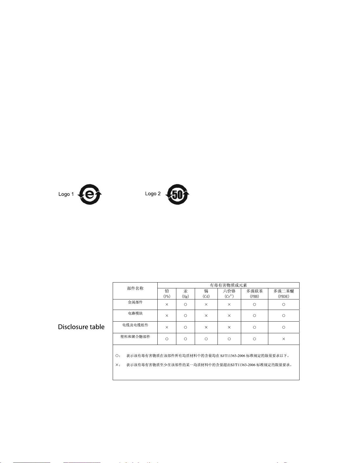
CMM labeling and disclosure table
■ ■ ■ ■ ■ ■ ■ ■ ■ ■ ■ ■ ■ ■ ■ ■ ■ ■ ■ ■ ■ ■ ■ ■ ■ ■ ■ ■ ■ ■ ■ ■ ■ ■ ■ ■ ■ ■ ■ ■ ■ ■ ■ ■ ■ ■ ■ ■ ■ ■ ■ ■ ■ ■ ■ ■ ■ ■ ■ ■ ■ ■
The P eople’s Republic of China require that our products comply with China Management
Methods (CMM) environmental regulations. (China Management Methods refers to the
regulation
T wo items are used to demonstrate compliance; the label and the disclosure table.
The label is placed in a customer visible position on the product.
• Logo 1 means the product contains no substances in excess of the maximum concentration
• Logo 2 means that the product may contain substances in excess of the maximum
Management Methods for Controlling P ollution by Electronic Information Products
value for materials identified in the China Management Methods regulation.
concentration value for materials identified in the China Management Methods regulation,
and has an Environmental Friendly Use P eriod (EFUP) in years, fifty years in the example
shown.
■
■
.)
The Environmental Friendly Use P eriod (EFUP) is the period (in years) during which the T oxic
and Hazardous Substances (T&HS) contained in the Electronic Information Product (EIP)
will not leak or mutate causing environmental pollution, or bodily injury from the use of the
EIP . The EFUP indicated by the Logo 2 label applies to a product and all its parts. Certain
field -replaceable parts, such as battery modules, can have a different EFUP and are marked
separately .
The Disclosure table is intended only to communicate compliance with China requirements.
It is not intended to communicate compliance with EU RoHS or any other environmental
requirements.
10 68P09286A73 -1
PRELIMINARY - UNDER DEVELOPMENT JUL 2007
Page 22

Motorola document set
Motorola document set
■ ■ ■ ■ ■ ■ ■ ■ ■ ■ ■ ■ ■ ■ ■ ■ ■ ■ ■ ■ ■ ■ ■ ■ ■ ■ ■ ■ ■ ■ ■ ■ ■ ■ ■ ■ ■ ■ ■ ■ ■ ■ ■ ■ ■ ■ ■ ■ ■ ■ ■ ■ ■ ■ ■ ■ ■ ■ ■ ■ ■ ■
The Motorola document sets provide the information to operate, install, and maintain the
Motorola equipment.
Ordering documents and CD -ROMs
W ith internet access available, to view , download, or order documents (original or revised), visit
the Motorola Lifecycles Customer web page at https://mynetworksupport.motorola.com , or
contact your Motorola account representative.
W ithout internet access available, order hard copy documents or CD -ROMs with your Motorola
Local Office or Representative.
If Motorola changes the content of a document after the original printing date, Motorola
publishes a new version with the same part number but a different revision character .
■
■
Document banner denitions
Data encryption
A banner (oversized text on the bottom of the page, for example, PRELIMINARY — UNDER
DEVELOPMENT ) indicates that some information contained in the document is not yet approved
for general customer use.
In order to avoid electronic eavesdropping, data passing between certain elements in the
network is encrypted. In order to comply with the export and import requirements of particular
countries, this encryption occurs at different levels as individually standardized, or may not be
present at all in some parts of the network in which it is normally implemented. The document
set, of which this document is a part, covers encryption as if fully implemented. Because the
rules differ in individual countries, limitations on the encryption included in the particular
software being delivered, are covered in the Release Notes that accompany the individual
software release.
68P09286A73 -1 11
JUL 2007 PRELIMINARY - UNDER DEVELOPMENT
Page 23

Supplemental information
Supplemental information
■ ■ ■ ■ ■ ■ ■ ■ ■ ■ ■ ■ ■ ■ ■ ■ ■ ■ ■ ■ ■ ■ ■ ■ ■ ■ ■ ■ ■ ■ ■ ■ ■ ■ ■ ■ ■ ■ ■ ■ ■ ■ ■ ■ ■ ■ ■ ■ ■ ■ ■ ■ ■ ■ ■ ■ ■ ■ ■ ■ ■ ■
Third party computer software and trademarks
Computer software
The following is a list of the 3rd party computer software copyrights contained within this
Motorola product.
Company Copyright
Apache Software F oundation* Copyright 2002-2007 All rights reserved.
Artesyn
CMU *
Freeware T ools / Utilities * Copyright 2002-2007 All rights reserved.
P erformance T echnologies Copyright 2002-2007 All rights reserved.
T elelogic Copyright 2002-2007 All rights reserved.
QNX *
W ind River Systems, Inc. Copyright 1984-2007 All rights reserved.
* Publicly A vailable Software
Copyright 2002-2007 All rights reserved.
Copyright 2002-2007 All rights reserved.
Copyright 2002-2007 All rights reserved.
■
■
Trademarks
Java™ T echnology and/or J2ME™: Java and all other Java -based marks are trademarks or
registered trademarks of Sun Microsystems, Inc. in the U .S . and other countries.
UNIX® : UNIX is a registered trademark of The Open Group in the United States and other
countries.
12 68P09286A73 -1
PRELIMINARY - UNDER DEVELOPMENT JUL 2007
Page 24

FCC requirements
FCC requirements
■ ■ ■ ■ ■ ■ ■ ■ ■ ■ ■ ■ ■ ■ ■ ■ ■ ■ ■ ■ ■ ■ ■ ■ ■ ■ ■ ■ ■ ■ ■ ■ ■ ■ ■ ■ ■ ■ ■ ■ ■ ■ ■ ■ ■ ■ ■ ■ ■ ■ ■ ■ ■ ■ ■ ■ ■ ■ ■ ■ ■ ■
Content
This section presents F ederal Communications Commission (FCC) Rules P arts 15 and 68
requirements and compliance information for the (W AP25400) MOTOwi4™ Diversity Access
P oint .
Radio frequency exposure
■
■
This equipment is designed to gener ate and r adiate r adio frequency (RF) energy . It
should be installed and maintained only b y tr ained technicians. Licensees of the
F eder al Communications Commission (FCC) using this equipment are responsible for
insuring that its installation and oper ation comply with FCC regulations (47 C.F .R. &
1.1310) designed to limit human exposure to RF energy .
FCC Part 15 requirements
Part 15.19a(3) - Information to user
This device complies with P art 15 of the FCC Rules. Operation is subject to the
following two conditions:
1. This device may not cause harmful interference, and
2. This device must accept any interference received, including interference that
may cause undesired operation
68P09286A73 -1 13
JUL 2007 PRELIMINARY - UNDER DEVELOPMENT
Page 25

FCC requirements
Part 15.21 - Information to user
Changes or modifications that change the FCC type approved configuration of the
equipment could void the user’s authority to operate the equipment.
15.105(b) - Information to user
This equipment has been tested and found to comply with the limits for a Class B
digital device, pursuant to P art 15 of the FCC Rules. These limits are designed
to provide reasonable protection against harmful interference in a residential
installation. This equipment generates, uses and can radiate radio frequency
energy and, if not installed and used in accordance with the instructions, may cause
harmful interference to radio communications. However , there is no guarantee that
interference will not occur in a particular installation. If this equipment does cause
harmful interference to radio or television reception, which can be determined by
turning the equipment OFF and ON , the user is encouraged to try to correct the
interference by one or more of the following measures:
• Reorient or relocate the receiving antenna
• Increase the separation between the equipment and receiver .
• Connect the equipment into an outlet on a circuit different from that to which
the receiver is connected.
• Connect the equipment into an outlet on a circuit different from that to which
the receiver is connected.
• Consult the dealer or an experienced radio/TV technician for help.
14 68P09286A73 -1
PRELIMINARY - UNDER DEVELOPMENT JUL 2007
Page 26
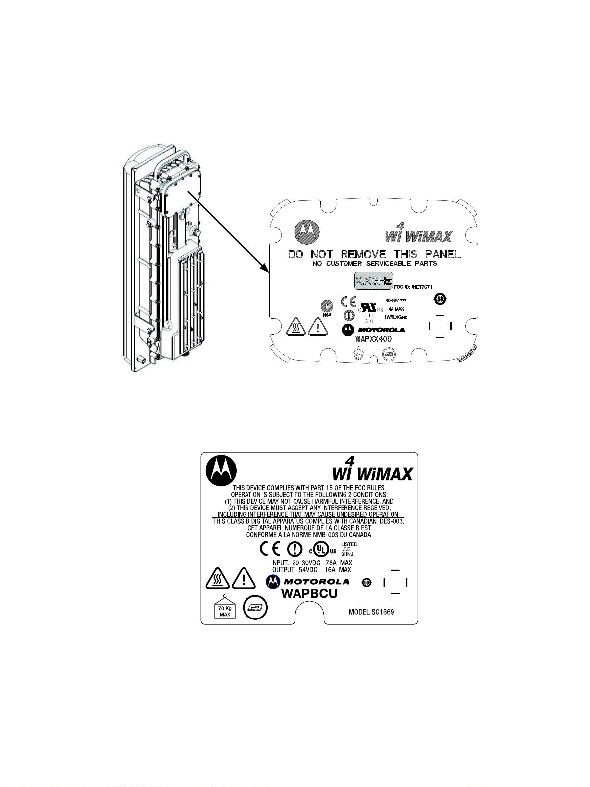
DAP label and location
ti_cdma_wimaxdap.eps
FCC requirements
A label similar to the one illustrated is located as shown. All symbols may not display on the
label depending on the market.
BCU label
A label similar to the one illustrated is located on the equipment. All symbols may not display on
the label depending on the market.
68P09286A73 -1 15
JUL 2007 PRELIMINARY - UNDER DEVELOPMENT
Page 27

FCC requirements
16 68P09286A73 -1
PRELIMINARY - UNDER DEVELOPMENT JUL 2007
Page 28

C h a p t e r
1
Overview
■ ■ ■ ■ ■ ■ ■ ■ ■ ■ ■ ■ ■ ■ ■ ■ ■ ■ ■ ■ ■ ■ ■ ■ ■ ■ ■ ■ ■ ■ ■ ■ ■ ■ ■ ■ ■ ■ ■ ■ ■ ■ ■ ■ ■ ■ ■ ■ ■ ■ ■ ■ ■ ■ ■ ■ ■ ■ ■ ■ ■ ■
■
■
■
■
68P09286A73 -1 1 -1
JUL 2007 PRELIMINARY - UNDER DEVELOPMENT
Page 29

Introduction Chapter 1: Ov erview
Introduction
■ ■ ■ ■ ■ ■ ■ ■ ■ ■ ■ ■ ■ ■ ■ ■ ■ ■ ■ ■ ■ ■ ■ ■ ■ ■ ■ ■ ■ ■ ■ ■ ■ ■ ■ ■ ■ ■ ■ ■ ■ ■ ■ ■ ■ ■ ■ ■ ■ ■ ■ ■ ■ ■ ■ ■ ■ ■ ■ ■ ■ ■
This document provides information pertaining to the hardware and cabling installation for the
outdoor and indoor (19 – inch rack) version of the
Hardware.
Motorola
Ground Based Access P oint (GAP)
■
■
This hardware installation manual
does not include
card and module placement, applying
power , tuning, network configuration, software site commissioning, troubleshooting, etcetera.
Refer to other associated manuals (product specific documentation, and product enabled, such
as on -line help on the LMT or EMS).
1 -2 68P09286A73 -1
PRELIMINARY - UNDER DEVELOPMENT JUL 2007
Page 30

Ground Based Access P oint (GAP) Hardw are Installation Product Description
Product Description
■ ■ ■ ■ ■ ■ ■ ■ ■ ■ ■ ■ ■ ■ ■ ■ ■ ■ ■ ■ ■ ■ ■ ■ ■ ■ ■ ■ ■ ■ ■ ■ ■ ■ ■ ■ ■ ■ ■ ■ ■ ■ ■ ■ ■ ■ ■ ■ ■ ■ ■ ■ ■ ■ ■ ■ ■ ■ ■ ■ ■ ■
The
Motorola
assemblies; the Base Transceiver (sub) System (BTS) and the Battery Backup Unit (BBU). T wo
configurations are available; an indoor GAP , and an outdoor GAP . The indoor configuration is
mounted in a standard 19–inch rack. The outdoor configuration is housed in two (typical)
weather resistant cabinets. The outdoor cabinets may be mounted side -by -side, or stacked
on top of each other .
The GAP BTS includes the Base Control Unit (B CU) cage and Transceiver modules (TRX) cage.
The B CU contains signal processing and interface hardware. The TRX module contains an
interface for the B CU , the TX (transmit) and RX (receive) components, and RF interface for the
RF antenna(s). The RF interface is an external connection between the TRX module(s) and the
RF antenna(s).
The GAP BBU (battery cabinet) is typically used in an outdoor configuration. The BBU contains
batteries and/or additional TRX module cages for multi sector configurations. F or indoor
configurations, the battery supply would come from the battery room at the customer site.
Ground – based Access P oint (GAP) hardware is made up of three main component
■
■
68P09286A73 -1 1 -3
PRELIMINARY - UNDER DEVELOPMENT JUL 2007
Page 31

Manual Order Chapter 1: Ov erview
Manual Order
■ ■ ■ ■ ■ ■ ■ ■ ■ ■ ■ ■ ■ ■ ■ ■ ■ ■ ■ ■ ■ ■ ■ ■ ■ ■ ■ ■ ■ ■ ■ ■ ■ ■ ■ ■ ■ ■ ■ ■ ■ ■ ■ ■ ■ ■ ■ ■ ■ ■ ■ ■ ■ ■ ■ ■ ■ ■ ■ ■ ■ ■
This section outlines the content of this manual.. The appendices provide additional information
about installation not otherwise covered in the chapters.
Chapter 1 – Overview This is a brief outline of the manual. It also provides a list of additional
documents and tools necessary to complete the procedures.
Chapter 2 – Site Preparation This chapter contains the information for site verification
and shipping and handling of the hardware.
Chapter 3 – Cable Descriptions This chapter contains general information on the cabling
available for the B CU and RF Head.
■
■
Chapter 4 – Indoor Ground -based Access P oint (GAP) Hardware Installation
This chapter contains general information and procedures for installing the indoor (19 - inch
rack) version of the Ground -based Access P oint (GAP) ardware
Chapter 5 – Outdoor Ground -based Access P oint (GAP) Hardware Installation
This chapter contains general information and procedures for installing the outdoor (weather resistant cabinet) version of the Ground -based Access P oint (GAP) ardware
Chapter 6– Optional Equipment
Chapter 7– What’s Next This chapter contains general information and procedures for
installing optional equipment.
Chapter 8– XXXXXXXXX This chapter contains general information and procedures for site
clean up and installation checklist.
Appendix A – Alternate RF Head Installation Procedure This appendix contains
general information and alternate procedures for RF Head installation.
Appendix B – Alternate RGPS Installation This appendix contains general information
and alternate procedures for RGPS installation.
Appendix C – MMI Cable F abrication This appendix contains general information and a
procedure for manufacturing an MMI cable if the SLN2006A Kit is not available.
1 -4 68P09286A73 -1
PRELIMINARY - UNDER DEVELOPMENT JUL 2007
Page 32

Ground Based Access P oint (GAP) Hardw are Installation R ecommended Documents
Recommended Documents
■ ■ ■ ■ ■ ■ ■ ■ ■ ■ ■ ■ ■ ■ ■ ■ ■ ■ ■ ■ ■ ■ ■ ■ ■ ■ ■ ■ ■ ■ ■ ■ ■ ■ ■ ■ ■ ■ ■ ■ ■ ■ ■ ■ ■ ■ ■ ■ ■ ■ ■ ■ ■ ■ ■ ■ ■ ■ ■ ■ ■ ■
The following documents may be required to assist in the installation of the GAP Hardware.
• Standards and Guidelines for Communication Sites
Hard copy (
Motorola
P art Number 6881089E50)
■
■
CD -ROM (
Motorola
P art Number 9882904Y01)
• Site Document (generated by
site specific documentation
channel allocation
contact list (customer)
ancillary/expendable equipment list
site wiring lists
contact list (Motorola support)
job box inventory
• Demarcation Document (Scope of W ork agreement)
• Installation manuals for non -
Motorola
Motorola
Systems Engineering), which includes:
equipment (for reference purposes).
68P09286A73 -1 1 -5
PRELIMINARY - UNDER DEVELOPMENT JUL 2007
Page 33

Abbreviations and Acron yms Chapter 1: Ov erview
Abbreviations and Acronyms
■ ■ ■ ■ ■ ■ ■ ■ ■ ■ ■ ■ ■ ■ ■ ■ ■ ■ ■ ■ ■ ■ ■ ■ ■ ■ ■ ■ ■ ■ ■ ■ ■ ■ ■ ■ ■ ■ ■ ■ ■ ■ ■ ■ ■ ■ ■ ■ ■ ■ ■ ■ ■ ■ ■ ■ ■ ■ ■ ■ ■ ■
T able 1 -1 lists the uncommon abbreviations and acronyms that appear within this manual.
Table 1 -1 Abbreviations and Acron yms
■
■
T erm
AP
BBU
B CU
B CU I/O
BTS
CB C
DAC
DAP
GAP
GPS
PSU
PSM
Access P oint
Battery Backup Unit
Base Control Unit
Base Control Unit Input/Output
Base Transceiver (sub) System
Circuit Breaker Card
Direct Air Cooling
Diversity Access P oint
Ground - based Access P oint
Global P ositioning System
P ower Supply Unit
P ower Supply Module
RFCU RF Carrier Unit
RF GPS
RGPS
RF Global P ositioning System (typically regarding antennas)
Remote Global P ositioning System (typically regarding
antennas with powered module / amplifier)
TRX
Transmit/Receive RF Module
Denition
1 -6 68P09286A73 -1
PRELIMINARY - UNDER DEVELOPMENT JUL 2007
Page 34

Ground Based Access P oint (GAP) Hardw are Installation T ools and Materials
Tools and Materials
■ ■ ■ ■ ■ ■ ■ ■ ■ ■ ■ ■ ■ ■ ■ ■ ■ ■ ■ ■ ■ ■ ■ ■ ■ ■ ■ ■ ■ ■ ■ ■ ■ ■ ■ ■ ■ ■ ■ ■ ■ ■ ■ ■ ■ ■ ■ ■ ■ ■ ■ ■ ■ ■ ■ ■ ■ ■ ■ ■ ■ ■
Introduction
Many of the tools and materials depend on the GAP installation, being indoor or outdoor . The
indoor GAP is mounted in a standard 19 - inch rack. The outdoor GAP is installed on a concrete
slab. T ools and materials also depend on the style of the wall or pole on which the RF Head
mounting bracket is being installed. Due to different mounting styles, additional tools and
materials may be required to meet site specific needs.
Tools and Materials
■
■
The tools and materials listed in T able 1 -2 are generally recommended to properly and safely
perform the various installation procedures. Not all tools will be used in all procedures.
Table 1 -2 T ools and Materials
Hand T ool Materials Purpose
Adjustable T orque ratchet
and metric/standard socket
set
Cordless P ower Drill, 3/8-in
or 1/2-in drive
Bucklestrap Cutting T ool (Motorola P/N 6604809N01) F or the pole mounting brackets
T ape Measure
Tin Snips
Safety Glasses Customer Supplied Eye Safety
Knife or Box Cutter Customer Supplied General purpose cutting
13/16 Breakaway T orque
W rench 38-in. lb
Crane or industrial fork lift
(must be rated for at least two
ton capacity)
Block and T ackle Customer Supplied High - capacity , 4 - point cable with hooks or
No . 2 Blade Screw Driver Customer Supplied General purpose
Customer Supplied F or general torquing of bolts and nuts.
Appropriate wood and
Drill holes in wood and light concrete
masonry drill bits (Standard
set may be adequate)
Customer Supplied
Customer Supplied General purpose measurement
Customer Supplied General purpose metal cutting
Customer Supplied
N Connectors
Customer Supplied Used to transport and support for GAP
cabinet(s)
carabiners used for transport and support for
GAP cabinet(s)
Continued
68P09286A73 -1 1 -7
PRELIMINARY - UNDER DEVELOPMENT JUL 2007
Page 35

T ools and Materials Chapter 1: Ov erview
Table 1 -2 T ools and Materials (Continued)
Hand T ool Materials Purpose
Electrical T ape Customer Supplied General purpose
Adjustable Crescent W rench Customer Supplied General purpose
T orx Screw Driver Set (T30
and lower)
Tie- W raps
Heat Shrink Tubing Customer Supplied General purpose, varying lengths and
Heat Shrink Gun Customer Supplied General purpose
Crimp T ool Customer Supplied Ground wires
Customer Supplied General purpose
Customer Supplied General purpose, varying lengths.
diameters
1 -8 68P09286A73 -1
PRELIMINARY - UNDER DEVELOPMENT JUL 2007
Page 36

C h a p t e r
2
Site Preparation
■ ■ ■ ■ ■ ■ ■ ■ ■ ■ ■ ■ ■ ■ ■ ■ ■ ■ ■ ■ ■ ■ ■ ■ ■ ■ ■ ■ ■ ■ ■ ■ ■ ■ ■ ■ ■ ■ ■ ■ ■ ■ ■ ■ ■ ■ ■ ■ ■ ■ ■ ■ ■ ■ ■ ■ ■ ■ ■ ■ ■ ■
This chapter provides general information for verification of the site prior to installation of
the GAP hardware.
■
■
■
■
68P09286A73 -1 2 -1
JUL 2007 PRELIMINARY - UNDER DEVELOPMENT
Page 37

Gener al Chapter 2: Site Prepar ation
General
■ ■ ■ ■ ■ ■ ■ ■ ■ ■ ■ ■ ■ ■ ■ ■ ■ ■ ■ ■ ■ ■ ■ ■ ■ ■ ■ ■ ■ ■ ■ ■ ■ ■ ■ ■ ■ ■ ■ ■ ■ ■ ■ ■ ■ ■ ■ ■ ■ ■ ■ ■ ■ ■ ■ ■ ■ ■ ■ ■ ■ ■
All customer sites have unique situations for installation of equipment. Specific site situations
that affect installation need to be identified, and resolved if necessary , prior to the actual
installation of any equipment.
Overview
The following sections provide the procedures and information to verify that the site is ready
for equipment installation. It also provides procedures to ensure the safety of the installation
personnel, protect the equipment from damage, and verify the site layout parameters.
■
■
Ev ery effort should be made to pro vide a safe working en vironment for all installation
and service personnel.
Indoor and outdoor sites
Both indoor and outdoor configurations need to include compliance with local, state and country
electrical and mechanical codes (building code). While low voltage for main power is typically
used, proper cabling of the correct specification for power is required. Equipment weight and
weight distribution needs to be considered for stable structural mounting. Adequate space
around the GAP unit is required for proper air flow and maintenance. F or indoor installations,
proper room temperature and clean air flow also needs to be considered. F or outdoor
installations, proper clearance for the cabinet and cabinet doors needs to be considered for
the installation and any subsequent maintenance procedures.
2 -2 68P09286A73 -1
PRELIMINARY - UNDER DEVELOPMENT JUL 2007
Page 38

Ground Based Access P oint (GAP) Hardw are Installation Site Prepar ation Ov erview
Site Preparation Overview
■ ■ ■ ■ ■ ■ ■ ■ ■ ■ ■ ■ ■ ■ ■ ■ ■ ■ ■ ■ ■ ■ ■ ■ ■ ■ ■ ■ ■ ■ ■ ■ ■ ■ ■ ■ ■ ■ ■ ■ ■ ■ ■ ■ ■ ■ ■ ■ ■ ■ ■ ■ ■ ■ ■ ■ ■ ■ ■ ■ ■ ■
This section provides the procedures and information to verify that the site is ready for
equipment installation. It also provides procedures to ensure the safety of the installation
personnel, protect the equipment from damage, and verify the site layout parameters.
Installation
The site preparation depends on the type of installation and the site characteristics. The Base
Control Unit (B CU) cage and associated TRX cage(s) may be installed indoors or outdoors.
Indoor installations require the use of 19–inch rack (open style). Outdoor installations require a
weatherproof enclosure (GAP cabinets). The RF and GPS antennas are cabled from the GAP
equipment and are mounted outdoors.
■
■
Site Manager
Verication and Procedures
The site manager is the person in charge of and is responsible for the full site.
V erifications typically have the installer check with the site manager that a condition has been
previously checked or procedure previously performed and meets a stated specification.
Inspections typically have the installer personally checking that a condition or item meets
stated specifications.
The verifications and procedures provided in this chapter are:
• Initial site inspections
• Preparing site for the arrival of equipment
• Site layout verification
68P09286A73 -1 2 -3
PRELIMINARY - UNDER DEVELOPMENT JUL 2007
Page 39

Initial site inspection Chapter 2: Site Prepar ation
Initial site inspection
■ ■ ■ ■ ■ ■ ■ ■ ■ ■ ■ ■ ■ ■ ■ ■ ■ ■ ■ ■ ■ ■ ■ ■ ■ ■ ■ ■ ■ ■ ■ ■ ■ ■ ■ ■ ■ ■ ■ ■ ■ ■ ■ ■ ■ ■ ■ ■ ■ ■ ■ ■ ■ ■ ■ ■ ■ ■ ■ ■ ■ ■
This section describes general items to consider for an initial site inspection.
Indoor intial site inspection
Indoor site inspections should include considerations for:
• General safety inspection to ensure a safe working environment for personnel and
protection of equipment.
• Lighting and power for installation and maintenance personnel.
• Appropriate general space to install the GAP frame equipment.
• A vailability of appropriate electrical ground connections for the GAP equipment.
■
■
• Access to, and routing of; input power , RF output, and general interconnection cabling
• A vailability of appropriate rated input power; battery or main line voltage and current.
• Minimum distance to access the front and rear of the GAP equipment.
• Minimum distance for air flow circulation around the GAP equipment.
• Level surface and enough floor support to handle the weight of the GAP equipment,
• Staging area for equipment arrival, unpacking, and transportation equipment for moving
• Compliance with any site engineering documentation and specifications.
Outdoor initial site inspection
Outdoor site inspections should include considerations for:
space for the rack mounted equipment.
frame, and cabling.
the GAP equipment.
2 -4 68P09286A73 -1
PRELIMINARY - UNDER DEVELOPMENT JUL 2007
Page 40

Ground Based Access P oint (GAP) Hardw are Installation Initial site inspection
• General safety inspection to ensure a safe working environment for personnel and
protection of equipment.
• Lighting and power for installation and maintenance personnel.
• Configuration of the GAP cabinets, either side - by - side or stacked.
• Appropriate general space to install the GAP cabinets.
• A vailability of appropriate electrical ground connections for the GAP equipment.
• Access to, and routing of; input power , RF output, and general interconnection cabling
space for the GAP cabinets.
• A vailability of appropriate rated input power; battery or main line voltage and current.
• Configuration and position of the concrete pad(s) to mount GAP cabinets.
• Level surface and the appropriate weight bearing characteristics of the concrete pad(s).
• Mounting structure for cable routing or environmental conditions; direct concrete
mounting or with bottom I -beam support.
• Minimum distance to access the front and rear of the GAP equipment.
• Minimum clearance to open doors and panels on the front and rear of the GAP cabinets.
• Minimum distance for air flow circulation around the GAP equipment.
• Staging area for equipment arrival, unpacking, and transportation equipment for moving
the GAP cabinets..
• Compliance with any site engineering documentation and specifications.
68P09286A73 -1 2 -5
PRELIMINARY - UNDER DEVELOPMENT JUL 2007
Page 41

Prepare Site for Equipment Arriv al Chapter 2: Site Prepar ation
Prepare Site for Equipment Arrival
■ ■ ■ ■ ■ ■ ■ ■ ■ ■ ■ ■ ■ ■ ■ ■ ■ ■ ■ ■ ■ ■ ■ ■ ■ ■ ■ ■ ■ ■ ■ ■ ■ ■ ■ ■ ■ ■ ■ ■ ■ ■ ■ ■ ■ ■ ■ ■ ■ ■ ■ ■ ■ ■ ■ ■ ■ ■ ■ ■ ■ ■
This section covers various topics not all of which are needed at every site. Based on the site
characteristics, execute the steps that apply to your site. Before installing the equipment, do the
following to ensure the safety of installation personnel and to protect the equipment.
Description
This information covers various topics not all of which are needed at every site. Based on the
site characteristics execute the steps that apply to your site. Before installing the equipment, do
the following to ensure the safety of installation personnel and to protect the equipment.
Equipment Arrival
■
■
Before the equipment arrives, indicate to the transport company an area (staging area) at
the site where the equipment can be unloaded and, if necessary , unpacked. The equipment
should be carefully delivered to the site, along with all equipment dollies and padding required
to safely move the equipment from the unloading area to the installation site. The following
should also be provided, outdoor weather protection, temporary lighting and power for lighting
and power tools.
Procedure to prepare the site for the equipment
Procedure 2 -1 Procedure to prepare the site for the GAP equipment
1
2
3
Consult with the site manager .
Locate the outdoor demarcation blocks for external (or internal, for rack
installations) utilities. V erify that they are shown on any site engineering
documents, and determine the required cable routing back to the equipment
frames.
V erify the following:
• AC or battery power is available and meets the site documentation
specifications
• Concrete pad, floor , outdoor pole and/or wall mounting structures are
installed (if needed) and meet specifications in the site engineering
documents
• Outdoor cable runs are installed and meet local building codes
• Customer input termination tie points are available
Continued
2 -6 68P09286A73 -1
PRELIMINARY - UNDER DEVELOPMENT JUL 2007
Page 42

Ground Based Access P oint (GAP) Hardw are Installation Prepare Site for Equipment Arriv al
Procedure 2 -1 Procedure to prepare the site for the GAP equipment (Continued)
• There is clear access to move the equipment to the desired mounting
area
• There is sufficient space for installation and service access to the
equipment
• Customer supplied shelters (if needed) are installed
4
5
Note any concerns or conditions that may create a safety hazard to personnel,
or impair the installtion of the GAP equipment.
68P09286A73 -1 2 -7
PRELIMINARY - UNDER DEVELOPMENT JUL 2007
Page 43

Site la y out inspection Chapter 2: Site Prepar ation
Site layout inspection
■ ■ ■ ■ ■ ■ ■ ■ ■ ■ ■ ■ ■ ■ ■ ■ ■ ■ ■ ■ ■ ■ ■ ■ ■ ■ ■ ■ ■ ■ ■ ■ ■ ■ ■ ■ ■ ■ ■ ■ ■ ■ ■ ■ ■ ■ ■ ■ ■ ■ ■ ■ ■ ■ ■ ■ ■ ■ ■ ■ ■ ■
Most of the site layout should have been inspected in the previous sections, and any special
conditions noted. Consult with the site manager to resolve any outstanding condition that
would impair the installation or safety of personnel. Correct all conditions and note any special
instructions needed to install the GAP equipment. V erify with the site manager that any special
instructions are related to the appropriate installation personnel.
■
■
2 -8 68P09286A73 -1
PRELIMINARY - UNDER DEVELOPMENT JUL 2007
Page 44

Ground Based Access P oint (GAP) Hardw are Installation Shipping and Handling
Shipping and Handling
■ ■ ■ ■ ■ ■ ■ ■ ■ ■ ■ ■ ■ ■ ■ ■ ■ ■ ■ ■ ■ ■ ■ ■ ■ ■ ■ ■ ■ ■ ■ ■ ■ ■ ■ ■ ■ ■ ■ ■ ■ ■ ■ ■ ■ ■ ■ ■ ■ ■ ■ ■ ■ ■ ■ ■ ■ ■ ■ ■ ■ ■
Overview
The purpose of this section is to describe how the GAP Base Transceiver (sub) System (BTS)
(includes the B CU and TRX), Battery Backup Unit (BBU) and RF Head are packaged for shipping
and how to correctly unpack the units in preparation for installation.
How Equipment is Shipped
■
■
The pallets containing the GAP equipment are hea vy and require the use of an
industrial fork -lift truck. F or the outdoor GAP cabinet, the fork lift truck should be
r ated to handle at least two tons.
The GAP can be shipped in several configurations. The outdoor GAP is shipped as two units
(typically as a BTS and a BBU). Both the GAP BTS and the GAP BBU are shipped on separate
pallets with cardboard box coverings. The indoor GAP is packaged as separate containers in
cardboard boxes strapped to a pallet. Plastic wrapping is used to encase the units and provide
protection as well as securing the units to the pallets.
F or indoor configurations, the B CU , and TRX cages, and other required and optional equipment,
will be shipped in separate containers or on separate pallets. The containers, if used, will either
be wood or cardboard, with packing material to protect the units.
F or the indoor GAP :
• The B CU cage is shipped with all cards/modules and internal cabling installed.
• The TRX cage is shipped with all cards/modules and internal cabling installed.
F or the outdoor GAP :
68P09286A73 -1 2 -9
PRELIMINARY - UNDER DEVELOPMENT JUL 2007
Page 45

Shipping and Handling Chapter 2: Site Prepar ation
• The BTS cabinet is shipped with the B CU cage with all cards/modules and internal cabling
installed.
• The BBU cabinet is shipped with all batteries and internal cabling installed.
• Depending on the ordered configuration, the TRX cage can be in either the BTS cabinet
and / or the BBU cabinet.
• The TRX cage, with the installed TRX modules, will have all internal cabling installed.
How Equipment Arrives
Before the equipment arrives, indicate to the transport company an area at the site where the
equipment can be unloaded and, if necessary , unpacked. The equipment should be carefully
delivered to the site, along with all equipment fork lift, dollies and padding required to safely
move the equipment from the unloading area to the cell site. The site should also have outdoor
weather protection and power for temporary lighting and power tools.
Recommended Unpacking Tools
The following tools are recommended to assist in opening the containers housing the equipment:
• Tin snips.
• Knife, box cutter , or scissors.
2 -10 68P09286A73 -1
PRELIMINARY - UNDER DEVELOPMENT JUL 2007
Page 46

Ground Based Access P oint (GAP) Hardw are Installation Unpacking
Unpacking
■ ■ ■ ■ ■ ■ ■ ■ ■ ■ ■ ■ ■ ■ ■ ■ ■ ■ ■ ■ ■ ■ ■ ■ ■ ■ ■ ■ ■ ■ ■ ■ ■ ■ ■ ■ ■ ■ ■ ■ ■ ■ ■ ■ ■ ■ ■ ■ ■ ■ ■ ■ ■ ■ ■ ■ ■ ■ ■ ■ ■ ■
This section describes unpacking the various units for the GAP .
GAP equipment
The GAP equipment is shipped either as and indoor unit and as an outdoor unit. The indoor unit
includes the B CU and TRX cages and is designed to fit in a standard 19–inch rack. The outdoor
unit is comprised of two outdoor cabinets, the BTS and BBU . Both the BTS and BBU cabinets are
pre -configured per order , and shipped with the internal cabling included.
Outdoor GAP
■
■
Installation of the two outdoor cabinets (BTS and BBU) mainly consists of mounting the unit,
grounding cabling, main power cabling, cabling between cabinets and cabling between the
TRX modules and the RF antennas.
68P09286A73 -1 2 -11
PRELIMINARY - UNDER DEVELOPMENT JUL 2007
Page 47

Unpacking Chapter 2: Site Prepar ation
PRELIMINARY ILLUSTRATION
Figure 2 -1 GAP cabinet - lifting and mounting br ack et locations
Unpacking procedure
Procedure 2 -2
1
2
3
4
5
2 -12 68P09286A73 -1
PRELIMINARY - UNDER DEVELOPMENT JUL 2007
Page 48

Ground Based Access P oint (GAP) Hardw are Installation Unpacking
Indoor GAP
The indoor B CU and TRX cages are internally cabled and installation mainly consists of
mounting the cages in the indoor rack, grounding cabling, main power cabling, cabling between
the cages, and cabling between the TRX modules and the RF antenna(s).
Unpacking procedure
Procedure 2 -3
1
2
3
4
5
68P09286A73 -1 2 -13
JUL 2007 PRELIMINARY - UNDER DEVELOPMENT
Page 49

Unpacking Chapter 2: Site Prepar ation
2 -14 68P09286A73 -1
PRELIMINARY - UNDER DEVELOPMENT JUL 2007
Page 50

C h a p t e r
3
Cable Descriptions
■ ■ ■ ■ ■ ■ ■ ■ ■ ■ ■ ■ ■ ■ ■ ■ ■ ■ ■ ■ ■ ■ ■ ■ ■ ■ ■ ■ ■ ■ ■ ■ ■ ■ ■ ■ ■ ■ ■ ■ ■ ■ ■ ■ ■ ■ ■ ■ ■ ■ ■ ■ ■ ■ ■ ■ ■ ■ ■ ■ ■ ■
Individual installations at customer sites vary . This chapter describes the typical cabling for the
GAP .
■
■
■
■
68P09286A73 -1 3 -1
JUL 2007 PRELIMINARY - UNDER DEVELOPMENT
Page 51

Ov erview Chapter 3: Cable Descriptions
Overview
■ ■ ■ ■ ■ ■ ■ ■ ■ ■ ■ ■ ■ ■ ■ ■ ■ ■ ■ ■ ■ ■ ■ ■ ■ ■ ■ ■ ■ ■ ■ ■ ■ ■ ■ ■ ■ ■ ■ ■ ■ ■ ■ ■ ■ ■ ■ ■ ■ ■ ■ ■ ■ ■ ■ ■ ■ ■ ■ ■ ■ ■
This chapter provides the descriptions of the site cabling.
Procedures for routing cables (through metallic or conductive conduit) to the outdoor equipment
are found in Chapter 4 Indoor GAP Hardware Installation .
Cabling is one of the most noticeable aspects of workmanship. Straight runs and
proper turns are critical for a positive evaluation of the work.
■
■
3 -2 68P09286A73 -1
PRELIMINARY - UNDER DEVELOPMENT JUL 2007
Page 52

Ground Based Access P oint (GAP) Hardw are Installation Congur ations Supported
Congurations Supported
■ ■ ■ ■ ■ ■ ■ ■ ■ ■ ■ ■ ■ ■ ■ ■ ■ ■ ■ ■ ■ ■ ■ ■ ■ ■ ■ ■ ■ ■ ■ ■ ■ ■ ■ ■ ■ ■ ■ ■ ■ ■ ■ ■ ■ ■ ■ ■ ■ ■ ■ ■ ■ ■ ■ ■ ■ ■ ■ ■ ■ ■
This chapter supports cable installation for 3 and 4 sector configurations.
■
■
68P09286A73 -1 3 -3
PRELIMINARY - UNDER DEVELOPMENT JUL 2007
Page 53

Cable Installation Order Chapter 3: Cable Descriptions
Cable Installation Order
■ ■ ■ ■ ■ ■ ■ ■ ■ ■ ■ ■ ■ ■ ■ ■ ■ ■ ■ ■ ■ ■ ■ ■ ■ ■ ■ ■ ■ ■ ■ ■ ■ ■ ■ ■ ■ ■ ■ ■ ■ ■ ■ ■ ■ ■ ■ ■ ■ ■ ■ ■ ■ ■ ■ ■ ■ ■ ■ ■ ■ ■
1. Ground Cabling
2. P ower Cabling
3. Antenna Cabling
4. RGPS or Local GPS Cabling
5. Ethernet Cabling
6. Fiber Optic Cabling
7. Customer Defined Input/Output Cabling
■
■
3 -4 68P09286A73 -1
PRELIMINARY - UNDER DEVELOPMENT JUL 2007
Page 54

Ground Based Access P oint (GAP) Hardw are Installation Cable Descriptions and P art Numbers
Cable Descriptions and Part Numbers
■ ■ ■ ■ ■ ■ ■ ■ ■ ■ ■ ■ ■ ■ ■ ■ ■ ■ ■ ■ ■ ■ ■ ■ ■ ■ ■ ■ ■ ■ ■ ■ ■ ■ ■ ■ ■ ■ ■ ■ ■ ■ ■ ■ ■ ■ ■ ■ ■ ■ ■ ■ ■ ■ ■ ■ ■ ■ ■ ■ ■ ■
T able 3 -1 gives the cable descriptions and part numbers of the various cables that connect the
GAP Base Control Unit (B CU), the GAP Battery Backup Unit (BBU), the GPS antenna, and the
RF head.
Table 3 -1 Cable Length R equirements
■
■
Cable Qty
A
B
C 1 T472AA
C1 1
D
E
F
G 1–4 3089298C01
H
Part Number Description
2
Customer Supplied Ground cable, 6 A WG or larger ,
insulated copper wire.
2–8 3089492T02
Antenna Cable, 300 mm (1 ft.)
RGPS cable, 15 m (50 ft.)
T472AB
T472AC
T472AD
T472AE
T472AF
RGPS cable, 38 m (125 ft.)
RGPS cable, 76 m (250 ft.)
RGPS cable, 152 m (500 ft.)
RGPS cable, 304 m (1000 ft.)
RGPS cable, 608 m (2000 ft.)
P art of Motorola Kit.
1 SGRG4030A
CGDSGPSKITF4NM50
Assembly , Receiver , GPS , RF Module
Antenna, GPS , with mounting and 50
ft. cable.
2
Customer Supplied AC P ower Cable, 10 A WG , copper
DC P ower Cable,
1 SGLN6414A
Assembly , Installation, Installation
HDW Pkg B CU
RF Head DC P ower Cable, 20 m (65.6
ft)
3089298C02
RF Head DC P ower Cable, 40 m (131.2
ft)
3089298C03
RF Head DC P ower Cable, 60 m (196.8
ft)
3089298C04
RF Head DC P ower Cable, 80 m (262.4
ft)
3089298C05
RF Head DC P ower Cable, 100 m
(328.0 ft)
1–4 3089843T01
Fiber Optic Cable, 20 m (65.6 ft)
3089843T02
Fiber Optic Cable, 40 m (131.2 ft)
Continued
68P09286A73 -1 3 -5
PRELIMINARY - UNDER DEVELOPMENT JUL 2007
Page 55

Cable Descriptions and P art Numbers Chapter 3: Cable Descriptions
Table 3 -1 Cable Length R equirements (Continued)
Cable Qty
J
K
L
M
Part Number Description
3089843T03
3089843T04
3089843T05
6
1 GCNTM20A3A
1 SGKN4386
1
Customer Supplied Ethernet cables, RJ-45 connectors,
CGDSVXL550
FSJ4–50B)
Customer Supplied DC power cable, 8–10 A WG , 10 m
Fiber Optic Cable, 60 m (196.8 ft)
Fiber Optic Cable, 80 m (262.4 ft)
Fiber Optic Cable, 100 m (328.0 ft)
straight
Assembly , Receiver , GPS , RF Module
Antenna, GPS , with
mounting and 50 ft. cable.
Antenna cable from Surge Arrestor
(Customer supplied) to B CU
Punch block to B CU I/O board, 15–pin
D -connector on one end and loose
wires on the other end. Cable is
Motorola P/N 3086433H12
3 -6 68P09286A73 -1
PRELIMINARY - UNDER DEVELOPMENT JUL 2007
Page 56

Ground Based Access P oint (GAP) Hardw are Installation Cable Lengths
Cable Lengths
■ ■ ■ ■ ■ ■ ■ ■ ■ ■ ■ ■ ■ ■ ■ ■ ■ ■ ■ ■ ■ ■ ■ ■ ■ ■ ■ ■ ■ ■ ■ ■ ■ ■ ■ ■ ■ ■ ■ ■ ■ ■ ■ ■ ■ ■ ■ ■ ■ ■ ■ ■ ■ ■ ■ ■ ■ ■ ■ ■ ■ ■
T able 3 -2 gives the typical lenghts of the various cabling.
Table 3 -2 Cable Lengths
■
■
From T o
B CU DC Source
B CU RF Connector
RF Head DC Connector
RF Head RF Connector
BBU DC Source B CU / TRX
AC Source
BBU Customer Interface
Compartment
DC Source
BBU Customer Interface
Compartment
Customer Output
Source
B CU Customer Interface
Compartment
Cable Cable Length
G
5 lengths, 20 to 100 m in 20 m
increments (65.6 to 328 ft)
B
E
E
F
300 mm (1 ft)
Length as required.
Length as required.
Length as required.
68P09286A73 -1 3 -7
JUL 2007 PRELIMINARY - UNDER DEVELOPMENT
Page 57

Cable Lengths Chapter 3: Cable Descriptions
3 -8 68P09286A73 -1
PRELIMINARY - UNDER DEVELOPMENT JUL 2007
Page 58

C h a p t e r
4
Indoor GAP Hardware Installation
■ ■ ■ ■ ■ ■ ■ ■ ■ ■ ■ ■ ■ ■ ■ ■ ■ ■ ■ ■ ■ ■ ■ ■ ■ ■ ■ ■ ■ ■ ■ ■ ■ ■ ■ ■ ■ ■ ■ ■ ■ ■ ■ ■ ■ ■ ■ ■ ■ ■ ■ ■ ■ ■ ■ ■ ■ ■ ■ ■ ■ ■
This chapter describes guidelines for installing the GAP hardware in an indoor rack.
■
■
■
■
68P09286A73 -1 4 -1
JUL 2007 PRELIMINARY - UNDER DEVELOPMENT
Page 59

Indoor (r ack - mount) GAP installation Chapter 4: Indoor GAP Hardw are Installation
Indoor (rack - mount) GAP installation
■ ■ ■ ■ ■ ■ ■ ■ ■ ■ ■ ■ ■ ■ ■ ■ ■ ■ ■ ■ ■ ■ ■ ■ ■ ■ ■ ■ ■ ■ ■ ■ ■ ■ ■ ■ ■ ■ ■ ■ ■ ■ ■ ■ ■ ■ ■ ■ ■ ■ ■ ■ ■ ■ ■ ■ ■ ■ ■ ■ ■ ■
This section provides information to install the Ground - based Access P oint (GAP) in an indoor
environment. This requires the use of a standard 19 - inch rack.
GAP rack - mount cages
Cards, modules, and batteries are installed separately in the GAP cages after the cages are
mounted in a standard 19 - inch rack. Installation of the cards, modules, and batteries are
customer site dependent, and are not specifically covered in this manual.
■
■
4 -2 68P09286A73 -1
PRELIMINARY - UNDER DEVELOPMENT JUL 2007
Page 60

Ground Based Access P oint (GAP) Hardw are Installation Indoor GAP product identication
Indoor GAP product identication
■ ■ ■ ■ ■ ■ ■ ■ ■ ■ ■ ■ ■ ■ ■ ■ ■ ■ ■ ■ ■ ■ ■ ■ ■ ■ ■ ■ ■ ■ ■ ■ ■ ■ ■ ■ ■ ■ ■ ■ ■ ■ ■ ■ ■ ■ ■ ■ ■ ■ ■ ■ ■ ■ ■ ■ ■ ■ ■ ■ ■ ■
his section shows the various configuration for indoor GAP cabinets.
BCU Cage and components
TRX cage and components
■
■
68P09286A73 -1 4 -3
PRELIMINARY - UNDER DEVELOPMENT JUL 2007
Page 61

R ack mounting congur ation Chapter 4: Indoor GAP Hardw are Installation
Rack mounting conguration
■ ■ ■ ■ ■ ■ ■ ■ ■ ■ ■ ■ ■ ■ ■ ■ ■ ■ ■ ■ ■ ■ ■ ■ ■ ■ ■ ■ ■ ■ ■ ■ ■ ■ ■ ■ ■ ■ ■ ■ ■ ■ ■ ■ ■ ■ ■ ■ ■ ■ ■ ■ ■ ■ ■ ■ ■ ■ ■ ■ ■ ■
This section shows the typical mounting configuration of the GAP cages in a standard 19 inch rack.
GAP rack mounting (typical)
■
■
4 -4 68P09286A73 -1
PRELIMINARY - UNDER DEVELOPMENT JUL 2007
Page 62

Ground Based Access P oint (GAP) Hardw are Installation Mounting and bolt congur ations
Mounting and bolt congurations
■ ■ ■ ■ ■ ■ ■ ■ ■ ■ ■ ■ ■ ■ ■ ■ ■ ■ ■ ■ ■ ■ ■ ■ ■ ■ ■ ■ ■ ■ ■ ■ ■ ■ ■ ■ ■ ■ ■ ■ ■ ■ ■ ■ ■ ■ ■ ■ ■ ■ ■ ■ ■ ■ ■ ■ ■ ■ ■ ■ ■ ■
This section describes different mounting bolt configurations and isolation considerations for
both indoor and outdoor GAP installations.
Ev ery effort should be made to pro vide a safe working en vironment for all installation
and service personnel.
■
■
Mounting hardware
Hilti Bolt
Isolation washer
The pallets containing the GAP equipment are hea vy and require the use of an
industrial fork -lift truck. F or the outdoor GAP , the fork lift truck should be r ated to
handle at least two tons (2000 lbs or 1000 kg).
The Hilti bolt is a concrete anchor and bolt. This is shown below in Figure 4 -1
The GAP cabinet(s) or rack floor mounting is typically isolated using nylon isolation washers,
and isolation pads bonded to the GAP floor mounting brackets. The islolation washer is shown
as optional parts in Figure 4 -1 and Figure 4 -2 . The isolation washer depicted in the figures is
combination washer and bushing.
Motorola
recommends that the isolation washer be used,
particularly for ease of installation, vibration supression, and particularly for maintaining
electrical ground isolation.
It may be necessary to ensure grounding isolation on an indoor GAP configuration using a rack.
The rack floor mounting hardware may need to be modified slighly (hole mounting diameter)
for the inclusion of the isolation washer . Additional isolation pads for the rack floor mounting
tabs may also be necessary .
68P09286A73 -1 4 -5
PRELIMINARY - UNDER DEVELOPMENT JUL 2007
Page 63

Mounting and bolt congur ations Chapter 4: Indoor GAP Hardw are Installation
ti-cdma-05742-cnc.eps
CONCRETE
HILTI-BOLT
HSL-3M 8/20
LARGE FLAT
WASHER
MOUNTING
BRACKET
ISOLATION
PAD
(AFFIXED
TO
BRACKET)
OPTIONAL
ISOLATION
WASHER
PRELIMINARY ILLUSTRATION
Installation on concrete
Concrete mounting is used in an outdoor GAP configuration. The same mounting can be used
for an indoor rack mounting on a concrete floor .
Due to the weight of the GAP cabinet, the supporting structure (concrete slab) must
be able to withstand at least 1000 lbs (500 kg).
Refer to Figure 4 -1 for a typical cross - section of the concrete bolt mounting to the GAP cabinet
or rack mounting brackets.
Figure 4 -1 Concrete mounting
Installation on wooden oor
W ooden floor mounting is typically used in an indoor GAP , rack mounting configuration.
4 -6 68P09286A73 -1
PRELIMINARY - UNDER DEVELOPMENT JUL 2007
Page 64

Ground Based Access P oint (GAP) Hardw are Installation Mounting and bolt congur ations
ti-cdma-05743-wd.eps
SMALL FLAT
WASHER
M12 X 100 BOL T
INSULATING WASHER
(OPTIONAL)
LARGE FLAT
WASHER
MOUTING
BRACKET
ISOLATION
PAD
MOUNTING
STRUCTURE
(I BEAM)
M12 NUT
LOCK WASHER
SMALL FLAT
WASHER
(AFFIXED TO
BRACKETS)
PRELIMINARY ILLUSTRATION
Due to the weight of the GAP components and r ack, the supporting structure (oor
deck) must be able to withstand at least 1000 lbs (500 kg). A structur al oor support,
such as an iron I -beam, underneath the wooden oor is recommended.
Refer to Figure 4 -2 for a typical cross - section of the wooden floor bolt mounting to the GAP
cabinet or rack mounting brackets.
Figure 4 -2 W ooden oor mounting
68P09286A73 -1 4 -7
PRELIMINARY - UNDER DEVELOPMENT JUL 2007
Page 65

Installation of GAP cages in the indoor r ack Chapter 4: Indoor GAP Hardw are Installation
Installation of GAP cages in the indoor rack
■ ■ ■ ■ ■ ■ ■ ■ ■ ■ ■ ■ ■ ■ ■ ■ ■ ■ ■ ■ ■ ■ ■ ■ ■ ■ ■ ■ ■ ■ ■ ■ ■ ■ ■ ■ ■ ■ ■ ■ ■ ■ ■ ■ ■ ■ ■ ■ ■ ■ ■ ■ ■ ■ ■ ■ ■ ■ ■ ■ ■ ■
BCU cage
TRX cage
■
■
4 -8 68P09286A73 -1
PRELIMINARY - UNDER DEVELOPMENT JUL 2007
Page 66

Ground Based Access P oint (GAP) Hardw are Installation R ack cabling with cages installed
Rack cabling with cages installed
■ ■ ■ ■ ■ ■ ■ ■ ■ ■ ■ ■ ■ ■ ■ ■ ■ ■ ■ ■ ■ ■ ■ ■ ■ ■ ■ ■ ■ ■ ■ ■ ■ ■ ■ ■ ■ ■ ■ ■ ■ ■ ■ ■ ■ ■ ■ ■ ■ ■ ■ ■ ■ ■ ■ ■ ■ ■ ■ ■ ■ ■
Cage to cage
External cabling to rack
■
■
68P09286A73 -1 4 -9
JUL 2007 PRELIMINARY - UNDER DEVELOPMENT
Page 67

R ack cabling with cages installed Chapter 4: Indoor GAP Hardw are Installation
4 -10 68P09286A73 -1
PRELIMINARY - UNDER DEVELOPMENT JUL 2007
Page 68

C h a p t e r
5
Outdoor GAP Hardware Installation
■ ■ ■ ■ ■ ■ ■ ■ ■ ■ ■ ■ ■ ■ ■ ■ ■ ■ ■ ■ ■ ■ ■ ■ ■ ■ ■ ■ ■ ■ ■ ■ ■ ■ ■ ■ ■ ■ ■ ■ ■ ■ ■ ■ ■ ■ ■ ■ ■ ■ ■ ■ ■ ■ ■ ■ ■ ■ ■ ■ ■ ■
This chapter describes guidelines for installing the GAP hardware cabinets in an outdoor
environment.
■
■
■
■
68P09286A73 -1 5 -1
JUL 2007 PRELIMINARY - UNDER DEVELOPMENT
Page 69

Outdoor (cabinet - mount) GAP installation Chapter 5: Outdoor GAP Hardw are Installation
Outdoor (cabinet - mount) GAP installation
■ ■ ■ ■ ■ ■ ■ ■ ■ ■ ■ ■ ■ ■ ■ ■ ■ ■ ■ ■ ■ ■ ■ ■ ■ ■ ■ ■ ■ ■ ■ ■ ■ ■ ■ ■ ■ ■ ■ ■ ■ ■ ■ ■ ■ ■ ■ ■ ■ ■ ■ ■ ■ ■ ■ ■ ■ ■ ■ ■ ■ ■
This section provides general information to install the Ground - based Access P oint (GAP) in an
outdoor environment. Each customer installation will vary . All outdoor GAP installations require
the use of a 5 - ft by 7 - ft concrete slab capable of supporting one ton (2000 lbs or 900 kg). Side
- by - side cabinets will require the use of two 5 - ft by 7 - ft concrete slabs.
GAP cabinets
The GAP cabinet comes pre -loaded with hardware cages. Cards, modules, and batteries are
installed separately in the GAP cages after the main mounting to a concrete or other support (re
- enforced floor) surface. Installation of the cards, modules, and batteries are customer site
dependent, and are not specifically covered in this manual.
■
■
The GAP cabinets are hea vy . The use of a cr ane and / or hoisting system that is r ated
to handle at least two tons (4000 lbs or 1800 kg) is recommended. A four -point
hoisting cable with appropriate hooks or car abiners should be used to unload the GAP
cabinet from the shipping pallet to the area of nal installation.
5 -2 68P09286A73 -1
PRELIMINARY - UNDER DEVELOPMENT JUL 2007
Page 70

Ground Based Access P oint (GAP) Hardw are Installation Outdoor GAP product identication and congur ations
Outdoor GAP product identication and congurations
■ ■ ■ ■ ■ ■ ■ ■ ■ ■ ■ ■ ■ ■ ■ ■ ■ ■ ■ ■ ■ ■ ■ ■ ■ ■ ■ ■ ■ ■ ■ ■ ■ ■ ■ ■ ■ ■ ■ ■ ■ ■ ■ ■ ■ ■ ■ ■ ■ ■ ■ ■ ■ ■ ■ ■ ■ ■ ■ ■ ■ ■
The following sections outline general mounting configurations for the GAP product. This
section also discusses common considerations when installing an outdoor GAP .
Common outdoor mounting information
This section outlines consideration common to any GAP outdoor installation. Concrete mounting
and general clearance information is provided.
Stacked GAP cabinet conguration
This section shows how a typical GAP is configured as a pair of stacked cabinets.
■
■
Side - by - side GAP cabinet conguration
This section shows how a typical GAP is configured as a pair of side - by - side cabinets.
68P09286A73 -1 5 -3
PRELIMINARY - UNDER DEVELOPMENT JUL 2007
Page 71

GAP concrete slab mounting Chapter 5: Outdoor GAP Hardw are Installation
GAP concrete slab mounting
■ ■ ■ ■ ■ ■ ■ ■ ■ ■ ■ ■ ■ ■ ■ ■ ■ ■ ■ ■ ■ ■ ■ ■ ■ ■ ■ ■ ■ ■ ■ ■ ■ ■ ■ ■ ■ ■ ■ ■ ■ ■ ■ ■ ■ ■ ■ ■ ■ ■ ■ ■ ■ ■ ■ ■ ■ ■ ■ ■ ■ ■
This section shows the typical mounting used on a concrete slab for the outdoor GAP cabinet(s).
This section also applies to mounting the cabinets on a concrete floor as well.
Installation Planning
Since customer site configurations vary , the mounting of the GAP cabinet on a concrete slab will
vary . The installation needs careful planning before installing the GAP cabinet(s). Customer site
physical dimensions, cabinet ventilation, adequate air space around the equipment, minimum
cabinet door clearance and power routing all contribute to how to plan out the installation. F or
utility mains power (AC power), local and country electrical code rules must also be taken into
consideration when planning the installation.
■
■
Concrete slab congurations
F or a single cabinet, a 5 ft by 7 ft concrete slab is required. This also is the basic footprint of the
door clearance needed around the GAP cabinet, when the cabinet is mounted in the center of
the concrete pad as viewed from the top of the GAP cabinet.
5 -4 68P09286A73 -1
PRELIMINARY - UNDER DEVELOPMENT JUL 2007
Page 72

Ground Based Access P oint (GAP) Hardw are Installation GAP concrete slab mounting
Y ILLUSTRATION
Figure 5 -1 Single cabinet mounting
68P09286A73 -1 5 -5
PRELIMINARY - UNDER DEVELOPMENT JUL 2007
Page 73

GAP concrete slab mounting Chapter 5: Outdoor GAP Hardw are Installation
PRELIMINARY ILLUSTRATION
Figure 5 -2 Dual cabinet mounting
Cabinet mounting
Depending on how the external power and interconnections are run to the cabinets, this will
determine if the GAP cabinets are mounted on a support between the concrete slab and the
cabinet(s). Routing of the external power and interconnections between the cabinets is through
the cabinet rear or underside of the cabinet. All external connection from a GAP cabinet is
through the BTS cabinet, namely the “mud room”. Figure 5 -3 shows the location of the mud
room area on the BTS cabinet.
5 -6 68P09286A73 -1
PRELIMINARY - UNDER DEVELOPMENT JUL 2007
Page 74

Ground Based Access P oint (GAP) Hardw are Installation GAP concrete slab mounting
PRELIMINARY ILLUSTRATION
Figure 5 -3 GAP B T S cabinet “mud room”
Conduit routed through back of BTS cabinet
Figure 5 -4 shows the conduit routed through the back of the BTS cabinet. This will not require a
support between the cainet and the conrete slab. The cabinet may be mounted directly to the
concrete slab.
68P09286A73 -1 5 -7
PRELIMINARY - UNDER DEVELOPMENT JUL 2007
Page 75

GAP concrete slab mounting Chapter 5: Outdoor GAP Hardw are Installation
PRELIMINARY ILLUSTRATION
Figure 5 -4 “Mud room” conduit routed through back of B T S cabinet
Conduit routed through bottom of BTS cabinet
Figure 5 -5 shows the conduit routed through the bottom of the BTS cabinet. This will require a
support between the cainet and the conrete slab.
5 -8 68P09286A73 -1
PRELIMINARY - UNDER DEVELOPMENT JUL 2007
Page 76

Ground Based Access P oint (GAP) Hardw are Installation GAP concrete slab mounting
PRELIMINARY ILLUSTRATION
Figure 5 -5 “Mud room” conduit routed through bottom of B T S cabinet
I -beam support
T o elevate the GAP cabinet from the concrete mounting, an I -beam support can be used. Three
I -beams are required for even support of the GAP cabinet. This description uses a 12 - inch
I -beam to allow clearance for a 90 - degree flexible conduit bend. F or utility mains power (AC
power), local and country electrical code rules must also be taken into consideration for a
minimum clearance bend.
X and Y show typical supports for the GAP cabinets. Note that all installations require mid support of the cabinet.
68P09286A73 -1 5 -9
PRELIMINARY - UNDER DEVELOPMENT JUL 2007
Page 77

GAP concrete slab mounting Chapter 5: Outdoor GAP Hardw are Installation
PRELIMINARY ILLUSTRATION
PRELIMINARY ILLUSTRATION
Figure 5 -6 I -beam support for a single GAP cabinet
Figure 5 -7 I -beam support for two GAP cabinets
5 -10 68P09286A73 -1
PRELIMINARY - UNDER DEVELOPMENT JUL 2007
Page 78

Ground Based Access P oint (GAP) Hardw are Installation Outdoor mounting and bolt congur ations
Outdoor mounting and bolt congurations
■ ■ ■ ■ ■ ■ ■ ■ ■ ■ ■ ■ ■ ■ ■ ■ ■ ■ ■ ■ ■ ■ ■ ■ ■ ■ ■ ■ ■ ■ ■ ■ ■ ■ ■ ■ ■ ■ ■ ■ ■ ■ ■ ■ ■ ■ ■ ■ ■ ■ ■ ■ ■ ■ ■ ■ ■ ■ ■ ■ ■ ■
The mounting of a GAP cabinet to an outdoor concrete slab is similar to mounting an indoor GAP
frame to a concrete floor . The same techniques are used. The use of plated or painted bolts is
recommended in the outdoor setting to resist rust.
Please refer to Mounting and bolt configurations on page 4 - 5 for information pertaining to
this topic.
■
■
68P09286A73 -1 5 -11
PRELIMINARY - UNDER DEVELOPMENT JUL 2007
Page 79

Concrete pad installation and ground system Chapter 5: Outdoor GAP Hardw are Installation
Concrete pad installation and ground system
■ ■ ■ ■ ■ ■ ■ ■ ■ ■ ■ ■ ■ ■ ■ ■ ■ ■ ■ ■ ■ ■ ■ ■ ■ ■ ■ ■ ■ ■ ■ ■ ■ ■ ■ ■ ■ ■ ■ ■ ■ ■ ■ ■ ■ ■ ■ ■ ■ ■ ■ ■ ■ ■ ■ ■ ■ ■ ■ ■ ■ ■
Materials needed
Also see the tools list in the beginning of this manual.
■
■
Table 5 -1 Gener al materials needed
Quantity
Description
Procedure 5 -1 Concrete pad and ground system Installation procedure
1
2
3
4
5
Ground system
5 -12 68P09286A73 -1
PRELIMINARY - UNDER DEVELOPMENT JUL 2007
Page 80

Ground Based Access P oint (GAP) Hardw are Installation Concrete pad installation and ground system
ti-cdma-01749.eps
CONCRETE
PAD
GROUNDING RING #3 BSWG
(#2 AWG;35 mm2) SOLID
COPPER W/TIN COATING
2438 mm
(96IN.)
GROUND
RODS (8−12)
GROUND TO CABINET (1 PER CABINET) #3 BSWG
(#2 AWG;35 mm2) SOLID COPPER W/TIN COATING
GROUND TO ANTENNA
#3 BSWG (#2 AWG; 35
mm2) SOLID COPPER
W/TIN COATING
609 mm
(2’ 0IN.)
GROUND TO REBAR
(CADWELD)
609 mm
(2’ 0IN.)
REBAR JOINTS
(CADWELD) (4)
609 mm
(2’ 0IN.)
REBAR
10 mm (3/8IN.)
MINIMUM.
FRONT
GROUND TO CABINET (1 PER CABINET) #3 BSWG (#2
AWG;35 mm2) SOLID COPPER W/TIN COATING
609 mm
(2’ 0IN.)
ti-cdma-01750.eps
CONDUIT STUBS ARE
TO BE 25 TO 50 MM (1IN.
TO 2IN.) ABOVE
CONCRETE PAD.
CONCRETE
PAD
Figure 5 -8 Ground ring la y out
Conduit routing through concrete slab
68P09286A73 -1 5 -13
Conduit routing is customer site dependant. This section is included here for installations that
use conduit routing integral to the concrete slab.
Figure 5 -9 Conduit stub in concrete slab
PRELIMINARY - UNDER DEVELOPMENT JUL 2007
Page 81

GAP side - b y - side congur ation Chapter 5: Outdoor GAP Hardw are Installation
PRELIMINARY ILLUSTRATION
GAP side - by - side conguration
■ ■ ■ ■ ■ ■ ■ ■ ■ ■ ■ ■ ■ ■ ■ ■ ■ ■ ■ ■ ■ ■ ■ ■ ■ ■ ■ ■ ■ ■ ■ ■ ■ ■ ■ ■ ■ ■ ■ ■ ■ ■ ■ ■ ■ ■ ■ ■ ■ ■ ■ ■ ■ ■ ■ ■ ■ ■ ■ ■ ■ ■
This section shows a typical installation of the GAP side - by - side cabinet configuration.
Side - by - side cabinets
Figure 5 -10 GAP cabinets
■
■
5 -14 68P09286A73 -1
PRELIMINARY - UNDER DEVELOPMENT JUL 2007
Page 82

Ground Based Access P oint (GAP) Hardw are Installation GAP stack ed congur ation
PRELIMINARY ILLUSTRATION
GAP stacked conguration
■ ■ ■ ■ ■ ■ ■ ■ ■ ■ ■ ■ ■ ■ ■ ■ ■ ■ ■ ■ ■ ■ ■ ■ ■ ■ ■ ■ ■ ■ ■ ■ ■ ■ ■ ■ ■ ■ ■ ■ ■ ■ ■ ■ ■ ■ ■ ■ ■ ■ ■ ■ ■ ■ ■ ■ ■ ■ ■ ■ ■ ■
Stacked cabinets
Figure 5 -11 GAP cabinets
■
■
68P09286A73 -1 5 -15
PRELIMINARY - UNDER DEVELOPMENT JUL 2007
Page 83

GAP Cabinet cabling Chapter 5: Outdoor GAP Hardw are Installation
GAP Cabinet cabling
■ ■ ■ ■ ■ ■ ■ ■ ■ ■ ■ ■ ■ ■ ■ ■ ■ ■ ■ ■ ■ ■ ■ ■ ■ ■ ■ ■ ■ ■ ■ ■ ■ ■ ■ ■ ■ ■ ■ ■ ■ ■ ■ ■ ■ ■ ■ ■ ■ ■ ■ ■ ■ ■ ■ ■ ■ ■ ■ ■ ■ ■
Grounding
Cabling between cabinets
■
■
External cabling to cabinets
Other cabling
5 -16 68P09286A73 -1
PRELIMINARY - UNDER DEVELOPMENT JUL 2007
Page 84

C h a p t e r
6
Optional Equipment
■ ■ ■ ■ ■ ■ ■ ■ ■ ■ ■ ■ ■ ■ ■ ■ ■ ■ ■ ■ ■ ■ ■ ■ ■ ■ ■ ■ ■ ■ ■ ■ ■ ■ ■ ■ ■ ■ ■ ■ ■ ■ ■ ■ ■ ■ ■ ■ ■ ■ ■ ■ ■ ■ ■ ■ ■ ■ ■ ■ ■ ■
■
■
■
■
68P09286A73 -1 6 -1
JUL 2007 PRELIMINARY - UNDER DEVELOPMENT
Page 85

GAP Cabinet cabling Chapter 6: Optional Equipment
6 -2 68P09286A73 -1
PRELIMINARY - UNDER DEVELOPMENT JUL 2007
Page 86

C h a p t e r
7
What’s Next and Cleanup
■ ■ ■ ■ ■ ■ ■ ■ ■ ■ ■ ■ ■ ■ ■ ■ ■ ■ ■ ■ ■ ■ ■ ■ ■ ■ ■ ■ ■ ■ ■ ■ ■ ■ ■ ■ ■ ■ ■ ■ ■ ■ ■ ■ ■ ■ ■ ■ ■ ■ ■ ■ ■ ■ ■ ■ ■ ■ ■ ■ ■ ■
■
■
■
■
68P09286A73 -1 7 -1
JUL 2007 PRELIMINARY - UNDER DEVELOPMENT
Page 87

Introduction Chapter 7: What ’ s Next and Cleanup
Introduction
■ ■ ■ ■ ■ ■ ■ ■ ■ ■ ■ ■ ■ ■ ■ ■ ■ ■ ■ ■ ■ ■ ■ ■ ■ ■ ■ ■ ■ ■ ■ ■ ■ ■ ■ ■ ■ ■ ■ ■ ■ ■ ■ ■ ■ ■ ■ ■ ■ ■ ■ ■ ■ ■ ■ ■ ■ ■ ■ ■ ■ ■
This section describes general information regarding the final steps of the installation.
These are:
• Clean up the site
• Fill out the installation completion checklist
• Optimize the system
Clean up the site
■
■
Installation checklist
Optimize the system
Clean up the site by following the information given in the
A fter the site is cleaned up, fill out the installation completion checklist. This checklist is located
in the
Installation Completion Checklist
Optimize the system by following the procedures given in the appropriate optimization and
other associated manuals (product specific, and product enabled, such as on -line help on the
LMT or EMS).
This hardware installation manual does not include card and module placement, applying power ,
tuning, network configuration, software site commissioning, troubleshooting, etcetera.
section of this chapter .
Site Cleanup
section in this chapter .
7 -2 68P09286A73 -1
PRELIMINARY - UNDER DEVELOPMENT JUL 2007
Page 88

Ground Based Access P oint (GAP) Hardw are Installation Site Cleanup
Site Cleanup
■ ■ ■ ■ ■ ■ ■ ■ ■ ■ ■ ■ ■ ■ ■ ■ ■ ■ ■ ■ ■ ■ ■ ■ ■ ■ ■ ■ ■ ■ ■ ■ ■ ■ ■ ■ ■ ■ ■ ■ ■ ■ ■ ■ ■ ■ ■ ■ ■ ■ ■ ■ ■ ■ ■ ■ ■ ■ ■ ■ ■ ■
Tools and storage
Place all hand and power tools in the installation tool kit or other appropriate place. Note any
tools that need replacement, cleaning, or adjustment. K eep any tools unique to the
equipment either at the site, or in an appropriate safe place for later use if needed, as specified
by the site manager .
Motorola
■
■
Materials storage
Debris cleanup
Environment
T ools unique to the
Motorola
site equipment can include, but are not limited to:
• K eys
• Special
Motorola
– supplied tools, such as a single -purpose security socket wrench
• Other third -party installation tools unique to the installation of the site equipment
Place any leftover (usable) materials in a location specified by the site manager .
Remove any packing material. Ensure that all scrap materials have been removed. Clean/sweep
the floor . Ensure that all chalk line marks have been removed..Appropriately dispose of any
hazardous waste as specified by the site manager .
Organize any items (manuals, materials, etc.) left on site and place them in a location specified
by the site manager .
Other items unique to the
68P09286A73 -1 7 -3
Motorola
site equipment can include, but are not limited to:
PRELIMINARY - UNDER DEVELOPMENT JUL 2007
Page 89

Site Cleanup Chapter 7: What ’ s Next and Cleanup
• Check for any safety hazards and correct if necessary as specified by the site manager .
• Site specific documentation
• Product manuals
• Other third -party installation documentation
• A copy of the installation checklist provided in this manual
7 -4 68P09286A73 -1
PRELIMINARY - UNDER DEVELOPMENT JUL 2007
Page 90

Ground Based Access P oint (GAP) Hardw are Installation Installation checklist
Installation checklist
■ ■ ■ ■ ■ ■ ■ ■ ■ ■ ■ ■ ■ ■ ■ ■ ■ ■ ■ ■ ■ ■ ■ ■ ■ ■ ■ ■ ■ ■ ■ ■ ■ ■ ■ ■ ■ ■ ■ ■ ■ ■ ■ ■ ■ ■ ■ ■ ■ ■ ■ ■ ■ ■ ■ ■ ■ ■ ■ ■ ■ ■
■
■
This section provides a
installation.
Installation completion checklist
Fill in and check the items listed in the Installation completion checklist on page 7 - 5 , (below)
comprised of T able 7 -1 and T able 7 -2
Directions
If this manual is provided in electronic form, print out the following installation checklist. If a
paper copy is provided, you may want to make a copy before filling out the checklist so that it
is separate from this manual. Refer to the site manager . Fill out the installation completion
checklist and make any necessary copies. Make copies of this checklist as needed. The item
numbers listed in T able 7 -2 do not represent a specific order , they are supplied for convenience.
general
list of items to be checked upon the completion of the site
Installation completion checklist
Some of the follwoing site information may not be available, such as a model number . Include a
short description of the site information as specified by the site manager .
Table 7 -1 Site information
Site information
Hardware installation completion
date:
Site: (name and description)
Serial number(s):
Model number(s):
Checklist completed by:
Checklist reviewed by:
68P09286A73 -1 7 -5
PRELIMINARY - UNDER DEVELOPMENT JUL 2007
Item entry
Page 91

Installation checklist Chapter 7: What ’ s Next and Cleanup
Table 7 -2 Checklist
Item
no.
1
Equipment is not damaged.
2
Air flow clearance requirements
are met.
Door opening clearance
requirements are met.
3
If indoor installation; GAP rack
is securely mounted to floor .
If outdoor installation; GAP
cabinet(s) is securely mounted to
floor or concrete slab.
If outdoor installation; GAP
cabinet(s) that are stacked are
securely mounted together .
If outdoor installation; GAP
cabling and conduit between
cabinets meet local code
requirments (for utility power),
and are installed correctly .
Flexible and rigid conduit is not
stressed.
4
B CU and RF Carrier Unit (RFCU)
are RF cabled correctly .
5
B CU and RFCU are DC power
cabled correctly .
6
B CU is ethernet cabled
(if installed).
Fiber optic, power and RF (if
required) cable between RF head
and GAP is installed correctly .
7
RF head is securely mounted to
pole.
RF head is correctly cabled.
8
Band pass filters are cabled to
RFCU correctly (if used).
9
Conduit is sufficiently grounded.
Item Notes
10
Antennas are grounded to tower .
11
The antenna cables are protected
by lightning arrestors (if
applicable).
12
GAP is grounded.
Continued
7 -6 68P09286A73 -1
PRELIMINARY - UNDER DEVELOPMENT JUL 2007
Page 92

Ground Based Access P oint (GAP) Hardw are Installation Installation checklist
Table 7 -2 Checklist (Continued)
Item
no.
13
RF Head is grounded.
14
RGPS is cabled to B CU .
15
RGPS head and mast are secure.
16
RGPS connection is protected
by lightning arrestors (if
applicable).
17
RGPS head has a clear view of
the sky and is not in a location
which accumulates debris. Make
sure the RGPS is located away
from the transmit antennas.
18
Local GPS (RF GPS) antenna is
secure (if used).
19
Local GPS cabling is installed (if
used).
20
Installation hardware is
removed.
21
The site is cleaned, swept and
trash removed.
22
The site specific documentation
is present at the site.
23
This installation checklist is
present at the site.
Item Notes
68P09286A73 -1 7 -7
JUL 2007 PRELIMINARY - UNDER DEVELOPMENT
Page 93

Installation checklist Chapter 7: What ’ s Next and Cleanup
7 -8 68P09286A73 -1
PRELIMINARY - UNDER DEVELOPMENT JUL 2007
Page 94

C h a p t e r
8
XXXXXXXXXXXX
■ ■ ■ ■ ■ ■ ■ ■ ■ ■ ■ ■ ■ ■ ■ ■ ■ ■ ■ ■ ■ ■ ■ ■ ■ ■ ■ ■ ■ ■ ■ ■ ■ ■ ■ ■ ■ ■ ■ ■ ■ ■ ■ ■ ■ ■ ■ ■ ■ ■ ■ ■ ■ ■ ■ ■ ■ ■ ■ ■ ■ ■
■
■
■
■
68P09286A73 -1 8 -1
JUL 2007 PRELIMINARY - UNDER DEVELOPMENT
Page 95

Installation checklist Chapter 8: XXXXXXXXXXXX
8 -2 68P09286A73 -1
PRELIMINARY - UNDER DEVELOPMENT JUL 2007
Page 96

C h a p t e r
9
XXXXXXXXXXXX
■ ■ ■ ■ ■ ■ ■ ■ ■ ■ ■ ■ ■ ■ ■ ■ ■ ■ ■ ■ ■ ■ ■ ■ ■ ■ ■ ■ ■ ■ ■ ■ ■ ■ ■ ■ ■ ■ ■ ■ ■ ■ ■ ■ ■ ■ ■ ■ ■ ■ ■ ■ ■ ■ ■ ■ ■ ■ ■ ■ ■ ■
■
■
■
■
68P09286A73 -1 9 -1
JUL 2007 PRELIMINARY - UNDER DEVELOPMENT
Page 97

Installation checklist Chapter 9: XXXXXXXXXXXX
9 -2 68P09286A73 -1
PRELIMINARY - UNDER DEVELOPMENT JUL 2007
Page 98

C h a p t e r
1 0
XXXXXXXXXXXX
■ ■ ■ ■ ■ ■ ■ ■ ■ ■ ■ ■ ■ ■ ■ ■ ■ ■ ■ ■ ■ ■ ■ ■ ■ ■ ■ ■ ■ ■ ■ ■ ■ ■ ■ ■ ■ ■ ■ ■ ■ ■ ■ ■ ■ ■ ■ ■ ■ ■ ■ ■ ■ ■ ■ ■ ■ ■ ■ ■ ■ ■
■
■
■
■
68P09286A73 -1 10 -1
JUL 2007 PRELIMINARY - UNDER DEVELOPMENT
Page 99

Installation checklist Chapter 10: XXXXXXXXXXXX
10 -2 68P09286A73 -1
PRELIMINARY - UNDER DEVELOPMENT JUL 2007
Page 100

C h a p t e r
1 1
XXXXXXXXXXXX
■ ■ ■ ■ ■ ■ ■ ■ ■ ■ ■ ■ ■ ■ ■ ■ ■ ■ ■ ■ ■ ■ ■ ■ ■ ■ ■ ■ ■ ■ ■ ■ ■ ■ ■ ■ ■ ■ ■ ■ ■ ■ ■ ■ ■ ■ ■ ■ ■ ■ ■ ■ ■ ■ ■ ■ ■ ■ ■ ■ ■ ■
■
■
■
■
68P09286A73 -1 11 -1
JUL 2007 PRELIMINARY - UNDER DEVELOPMENT
 Loading...