

Page 1

SCt4812ET RF and Power Cabinet
Hardware Installation Manual
System Software Release 2.16.0
English
Apr 2001
68P09253A94–1
800/1700/1900 MHz
CDMA
DRAFT
Page 2

SCt4812ET RF and Power Cabinet Hardware
Installation Manual
800/1700/1900 MHz
CDMA
English
Apr 2001
68P09253A94–1
Page 3

SCt4812ET RF and Power Cabinet
Hardware Install ation Manual
System Software Release 2.16.0
English
Apr 2001
68P09253A94–1
800/1700/1900 MHz
CDMA
DRAFT
Page 4

Notice
While reasonable efforts have been made to assure the accuracy of this document, Motorola, Inc. assumes no liability resulting from any
inaccuracies or omissions in this document, or from use of the information obtained herein. The information in this document has been
carefully checked and is believed to be entirely reliable. However, no responsibility is assumed for inaccuracies or omissions. Motorola,
Inc. reserves the right to make changes to any products described herein and reserves the right to revise this document and to make
changes from time to time in content hereof with no obligation to notify any person of revisions or changes. Motorola, Inc. does not
assume any liability arising out of the application or use of any product, software, or circuit described herein; neither does it convey
license under its patent rights or the rights of others.
It is possible that this publication may contain references to, or information about Motorola products (machines and programs),
programming, or services that are not announced in your country. Such references or information must not be construed to mean
that Motorola intends to announce such Motorola products, programming, or services in your country.
Copyrights
This instruction manual, and the Motorola products described in this instruction manual may be, include or describe copyrighted
Motorola material, such as computer programs stored in semiconductor memories or other media. Laws in the United States and
other countries preserve for Motorola certain exclusive rights for copyrighted material, including the exclusive right to copy,
reproduce in any form, distribute and make derivative works of the copyrighted material. Accordingly, any copyrighted Motorola
material contained herein or in the Motorola products described in this instruction manual may not be copied, reproduced,
distributed, merged or modified in any manner without the express written permission of Motorola. Furthermore, the purchase of
Motorola products shall not be deemed to grant either directly or by implication, estoppel, or otherwise, any license under the
copyrights, patents or patent applications of Motorola, as arises by operation of law in the sale of a product.
Usage and Disclosure Restrictions
License Agreement
The software described in this document is the property of Motorola, Inc. It is furnished by express license agreement only and may
be used only in accordance with the terms of such an agreement.
Copyrighted Materials
Software and documentation are copyrighted materials. Making unauthorized copies is prohibited by law. No part of the software or
documentation may be reproduced, transmitted, transcribed, stored in a retrieval system, or translated into any language or
computer language, in any form or by any means, without prior written permission of Motorola, Inc.
High Risk Activities
Components, units, or third–party products used in the product described herein are NOT fault–tolerant and are NOT designed,
manufactured, or intended for use as on–line control equipment in the following hazardous environments requiring fail–safe
controls: the operation of Nuclear Facilities, Aircraft Navigation or Aircraft Communication Systems, Air Traffic Control, Life
Support, or W eapons Systems (“High Risk Activities”). Motorola and its supplier(s) specifically disclaim any expressed or implied
warranty of fitness for such High Risk Activities.
Trademarks
and Motorola are registered trademarks of Motorola, Inc.
Product and service names profiled herein are trademarks of Motorola, Inc. Other manufacturers’ products or services profiled
herein may be referred to by trademarks of their respective companies.
Copyright
Copyright 2000 Motorola, Inc.
All Rights Reserved
Printed on
Recyclable Paper
SPECIFICATIONS SUBJECT TO CHANGE WITHOUT NOTICE
REV010598
Page 5

TM
4812ET RF and Power Cabinet Hardware Installation Manual
SC
This manual includes...
Chapter Version Description Page
Front
1
2
3
4
5
6
A
B
C
D
E
F
G
H
I
V00.04
V01.03
V02.03
V03.03
V04.03
V05.03
V06.03
V0A.03
VOB.03
VOC.03
VOD.03
V0F.02
V0F.02
VOG.01
VOH.01
VOI.01
Table of Contents
Release 2.16.0
Foreword, General Safety, Revision History, Patent
Notification
Introduction 13
Site Preparation 33
How to Unpack the SC 4812ET BTS 59
Cabinet Mounting 67
Cabinet Cabling 81
What’s Next and Cleanup 119
Installing RGPS 123
Cabinet Specifications 127
Hardware Installation Quickstart 137
SC 4812ET/SC 614 BTS Power Sharing 145
SC 4812ET – SC 614/SC 614T Companion Frame
Installation
SC 4812ET to SC 4812ET Power Sharing 169
SC 4812ET – SC 4812ET Companion Frame
Installation
Installing RF GPS 181
Minimum Requirements for CSU 185
3
157
185
Apr 2001
V00.04
Index 189
SCTM 4812ET RF and Power Cabinet Hardware Installation Manual
DRAFT
5
Page 6
Foreword
Scope of manual
Text conventions
This manual is intended for use by cellular telephone system
craftspersons in the day-to-day operation of Motorola cellular system
equipment and ancillary devices. It is assumed that the user of this
information has a general understanding of telephony, as used in the
operation of the Public Switched Telephone Network (PSTN), and is
familiar with these concepts as they are applied in the cellular
mobile/portable radiotelephone environment. The user, however, is not
expected to have any detailed technical knowledge of the internal
operation of the equipment.
This manual is not intended to replace the system and equipment
training offered by Motorola, although it can be used to supplement or
enhance the knowledge gained through such training.
The following special paragraphs are used in this manual to point out
information that must be read. This information may be set-off from the
surrounding text, but is always preceded by a bold title in capital letters.
The four categories of these special paragraphs are:
*
NOTE
Presents additional, helpful, non-critical information that
you can use.
IMPORTANT
Presents information to help you avoid an undesirable
situation or provides additional information to help you
understand a topic or concept.
CAUTION
Presents information to identify a situation in which
equipment damage could occur, thus avoiding damage to
equipment.
WARNING
Presents information to warn you of a potentially
hazardous situation in which there is a possibility of
personal injury.
. . . continued on next page
6
SCTM 4812ET RF and Power Cabinet Hardware Installation Manual
DRAFT
Apr 2001
V00.04
Page 7

Changes to manual
Foreword
– continued
The following typographical conventions are used for the presentation of
software information:
S In text, sans serif BOLDFACE CAPITAL characters (a type style
without angular strokes: i.e., SERIF versus SANS SERIF) are used to
name a command.
S In text, typewriter style characters represent prompts and the
system output as displayed on an operator terminal or printer.
S In command definitions, sans serif boldface characters represent those
parts of the command string that must be entered exactly as shown and
typewriter style characters represent command output responses
as displayed on an operator terminal or printer.
S In the command format of the command definition, typewriter
style characters represent the command parameters.
Changes that occur after the printing date are incorporated into your
manual by Cellular Manual Revisions (CMRs). The information in this
manual is updated, as required, by a CMR when new options and
procedures become available for general use or when engineering
changes occur. The cover sheet(s) that accompany each CMR should be
retained for future reference. Refer to the Revision History page for a list
of all applicable CMRs contained in this manual.
Receiving updates
Technical Education & Documentation (TED) maintains a customer
database that reflects the type and number of manuals ordered or shipped
since the original delivery of your Motorola equipment. Also identified
in this database is a “key” individual (such as Documentation
Coordinator or Facility Librarian) designated to receive manual updates
from TED as they are released.
To ensure that your facility receives updates to your manuals, it is
important that the information in our database is correct and up-to-date.
Therefore, if you have corrections or wish to make changes to the
information in our database (i.e., to assign a new “key” individual),
please contact Technical Education & Documentation at:
MOTOROLA, INC.
Technical Education & Documentation
1 Nelson C. White Parkway
Mundelein, Illinois 60060
U.S.A.
Phone:
Within U.S.A. and Canada 800-872-8225. . . . .
Outside of U.S.A. and Canada +1-847-435–5700. .
FAX: +1-847-435–5541. . . . . . . . . . . . . . . . . . . . . .
. . . continued on next page
Apr 2001
V00.04
SCTM 4812ET RF and Power Cabinet Hardware Installation Manual
DRAFT
7
Page 8

Foreword
– continued
Reporting manual errors
24-hour support service
In the event that you locate an error or identify a deficiency in your
manual, please take time to write to us at the address above. Be sure to
include your name and address, the complete manual title and part
number (located on the manual spine, cover, or title page), the page
number (found at the bottom of each page) where the error is located,
and any comments you may have regarding what you have found. We
appreciate any comments from the users of our manuals.
If you have any questions or concerns regarding the operation of your
equipment, please contact the Customer Network Resolution Center for
immediate assistance. The 24 hour telephone numbers are:
Arlington Heights, IL 800–433–5202. . . . . . . . .
Arlington Heights, International +1–847–632–5390.
Cork, Ireland 44–1793–565444. . . . . . . . . . . . . . . .
Swindon, England 44–1793–565444. . . . . . . . . . . . .
8
SCTM 4812ET RF and Power Cabinet Hardware Installation Manual
DRAFT
Apr 2001
V00.04
Page 9

Remember! . . . Safety
depends on you!!
Ground the instrument
General Safety
The following general safety precautions must be observed during all
phases of operation, service, and repair of the equipment described in
this manual. Failure to comply with these precautions or with specific
warnings elsewhere in this manual violates safety standards of design,
manufacture, and intended use of the equipment. Motorola, Inc. assumes
no liability for the customer’s failure to comply with these requirements.
The safety precautions listed below represent warnings of certain dangers
of which we are aware. You, as the user of this product, should follow
these warnings and all other safety precautions necessary for the safe
operation of the equipment in your operating environment.
To minimize shock hazard, the equipment chassis and enclosure must be
connected to an electrical ground. The BTS must be connected to a
permanent terminal, and not via a plug to ensure a firm ground at all
times.
Do not operate in an explosive
atmosphere
Keep away from live circuits
Do not service or adjust alone
Do not operate the equipment in the presence of flammable gases or
fumes. Operation of any electrical equipment in such an environment
constitutes a definite safety hazard.
Operating personnel must:
S not remove equipment covers. Only Factory Authorized Service
Personnel or other qualified maintenance personnel may remove
equipment covers for internal subassembly, or component
replacement, or any internal adjustment.
S not replace components with power cable connected. Under certain
conditions, dangerous voltages may exist even with the power cable
removed.
S always disconnect power and discharge circuits before touching them.
Do not attempt internal service or adjustment, unless another person,
capable of rendering first aid and resuscitation, is present.
Do not substitute parts or
modify equipment
Apr 2001
V00.04
SCTM 4812ET RF and Power Cabinet Hardware Installation Manual
Because of the danger of introducing additional hazards, do not install
substitute parts or perform any unauthorized modification of equipment.
Contact Motorola Warranty and Repair for service and repair to ensure
that safety features are maintained.
9
DRAFT
Page 10

General Safety
– continued
Dangerous procedure
warnings
Warnings, such as the example below, precede potentially dangerous
procedures throughout this manual. Instructions contained in the
warnings must be followed. You should also employ all other safety
precautions that you deem necessary for the operation of the equipment
in your operating environment.
WARNING
Dangerous voltages, capable of causing death, are present in this
equipment. Use extreme caution when handling, testing, and
adjusting.
10
SCTM 4812ET RF and Power Cabinet Hardware Installation Manual
DRAFT
Apr 2001
V00.04
Page 11

Manual Number
Manual Title
Version Information
Revision History
68P09253A94
TM
4812ET RF and Power Cabinet Hardware Installation Manual
SC
The following table lists the manual version, date of version, and
remarks on the version.
Version
Date of Issue Remarks
Level
1 Apr 2001 Original draft from engineering
Apr 2001
V00.04
SCTM 4812ET RF and Power Cabinet Hardware Installation Manual
DRAFT
11
Page 12

Patent Notification
Patent numbers
4128740 4661790 4860281 5036515 5119508 5204876 5247544 5301353
4193036 4667172 4866710 5036531 5121414 5204977 5251233 5301365
4237534 4672657 4870686 5038399 5123014 5207491 5255292 5303240
4268722 4694484 4872204 5040127 5127040 5210771 5257398 5303289
4282493 4696027 4873683 5041699 5127100 5212815 5259021 5303407
4301531 4704734 4876740 5047762 5128959 5212826 5261119 5305468
4302845 4709344 4881082 5048116 5130663 5214675 5263047 5307022
4312074 4710724 4885553 5055800 5133010 5214774 5263052 5307512
4350958 4726050 4887050 5055802 5140286 5216692 5263055 5309443
4354248 4729531 4887265 5058136 5142551 5218630 5265122 5309503
4367443 4737978 4893327 5060227 5142696 5220936 5268933 5311143
4369516 4742514 4896361 5060265 5144644 5222078 5271042 5311176
4369520 4751725 4910470 5065408 5146609 5222123 5274844 5311571
4369522 4754450 4914696 5067139 5146610 5222141 5274845 5313489
4375622 4764737 4918732 5068625 5152007 5222251 5276685 5319712
4485486 4764849 4941203 5070310 5155448 5224121 5276707 5321705
4491972 4775998 4945570 5073909 5157693 5224122 5276906 5321737
4517561 4775999 4956854 5073971 5159283 5226058 5276907 5323391
4519096 4797947 4970475 5075651 5159593 5228029 5276911 5325394
4549311 4799253 4972355 5077532 5159608 5230007 5276913 5327575
4550426 4802236 4972432 5077741 5170392 5233633 5276915 5329547
4564821 4803726 4979207 5077757 5170485 5235612 5278871 5329635
4573017 4811377 4984219 5081641 5170492 5235614 5280630 5339337
4581602 4811380 4984290 5083304 5182749 5239294 5285447 D337328
4590473 4811404 4992753 5090051 5184349 5239675 5287544 D342249
4591851 4817157 4998289 5093632 5185739 5241545 5287556 D342250
4616314 4827507 5020076 5095500 5187809 5241548 5289505 D347004
4636791 4829543 5021801 5105435 5187811 5241650 5291475 D349689
4644351 4833701 5022054 5111454 5193102 5241688 5295136 RE31814
4646038 4837800 5023900 5111478 5195108 5243653 5297161
4649543 4843633 5028885 5113400 5200655 5245611 5299228
4654655 4847869 5030793 5117441 5203010 5245629 5301056
4654867 4852090 5031193 5119040 5204874 5245634 5301188
This product is manufactured and/or operated under one or more of the
following patents and other patents pending:
12
SCTM 4812ET RF and Power Cabinet Hardware Installation Manual
DRAFT
Apr 2001
V00.04
Page 13

This section includes...
1
Chapter 1: Introduction
Product Description 14. . . . . . . . . . . . . . . . . . . . . . . . . . . . . . . . . .
Scope of this Document 14. . . . . . . . . . . . . . . . . . . . . . . . . . . . . . .
Manual Overview 14. . . . . . . . . . . . . . . . . . . . . . . . . . . . . . . . . . . .
Recommended Documents 15. . . . . . . . . . . . . . . . . . . . . . . . . . . . .
Acronyms 16. . . . . . . . . . . . . . . . . . . . . . . . . . . . . . . . . . . . . . . . . .
Installation Hardware 18. . . . . . . . . . . . . . . . . . . . . . . . . . . . . . . . .
Recommended Tools 20. . . . . . . . . . . . . . . . . . . . . . . . . . . . . . . . .
Materials Available from Motorola 21. . . . . . . . . . . . . . . . . . . . . .
RF Cabinet External FRUs 23. . . . . . . . . . . . . . . . . . . . . . . . . . . . .
RF Cabinet Internal FRUs 25. . . . . . . . . . . . . . . . . . . . . . . . . . . . .
Power Cabinet 27. . . . . . . . . . . . . . . . . . . . . . . . . . . . . . . . . . . . . . .
Power Cabinet Internal FRUs 28. . . . . . . . . . . . . . . . . . . . . . . . . . .
Enclosure Dimensions 29. . . . . . . . . . . . . . . . . . . . . . . . . . . . . . . .
Enclosure Clearances 30. . . . . . . . . . . . . . . . . . . . . . . . . . . . . . . . .
Tables
Table 1-1: Acronyms 16. . . . . . . . . . . . . . . . . . . . . . . . . . . . . . . . .
Table 1-2: Installation Hardware Supplied with Cabinets 18. . . . .
Table 1-3: Recommended Tools 20. . . . . . . . . . . . . . . . . . . . . . . .
Table 1-4: Cables, Tools and Hardware 21. . . . . . . . . . . . . . . . . . .
Table 1-5: Cabinet Dimension 29. . . . . . . . . . . . . . . . . . . . . . . . . .
Figures
Figure 1-1: SC 4812ET Installation Hardware 19. . . . . . . . . . . . . .
Figure 1-2: SC 4812ET RF Cabinet 22. . . . . . . . . . . . . . . . . . . . .
Figure 1-3: RF Cabinet External FRUs 23. . . . . . . . . . . . . . . . . . .
Figure 1-4: SC 4812ET LPAs 23. . . . . . . . . . . . . . . . . . . . . . . . . . .
Figure 1-5: External Blower Assembly (EBA) 24. . . . . . . . . . . . .
Figure 1-6: RF Cabinet Internal FRUs 25. . . . . . . . . . . . . . . . . . .
Figure 1-7: Power Cabinet 27. . . . . . . . . . . . . . . . . . . . . . . . . . . . .
Figure 1-8: Power Cabinet with Batteries Installed 28. . . . . . . . .
Figure 1-9: Minimum Cabinet Clearances 30. . . . . . . . . . . . . . . . .
Figure 1-10: Min. Site Clearances for SC 4812ET Cabinets 31. .
Apr 2001
V02.03
SCTM 4812ET RF and Power Cabinet Hardware Installation Manual
DRAFT
13
Page 14

1
Introduction
– continued
Product Description
The SC 4812ET BTS consists of an RF Cabinet that is an outdoor,
weatherized version of the SC 4812T. The RF cabinet is powered by 27
VDC and each cabinet has the capability to support up to 4 carriers (at 3
sector) or 2 carriers (at 6 sector). An optional outdoor, weatherized
Power Cabinet that provides AC/DC rectified power and battery back–up
is also available. An air to air heat exchanger is used for conditioning
each cabinet, except in the LPA area of the RF cabinet which uses
blower fans to draw outside air over the LPAs.
The SC 4812T utilizes a new RF “Trunking” technique that provides
shared power between sectors and increased RF output capability. The
SC 4812ET will support additional expansion cabinets to add more
carriers. Duplexer/Directional couplers will be standard equipment for
the SC 4812ET BTS.
The RF Cabinet houses the fan modules, Combined CDMA Channel
Processor shelf (C–CCP), Linear Power Amplifiers (LPA) modules, LPA
trunking backplane, Bandpass 2:1 & 4:1 Combiners, Duplexer/Receive
Filter/Directional Couplers (DRDC) and a DC Power distribution
assembly. The Power Cabinet (PC) provides +27 V DC distribution and
battery backup for the SC 4812ET. The Power Cabinet houses batteries,
battery heaters, rectifiers, an AC Load Center (ACLC), a power
distribution assembly, and two duplexed GFCI convenience outlets.
Scope of This
Document
Manual Overview
This document provides information pertaining to the installation of the
Motorola SC4812ET CDMA Base Transceiver Subsystem (BTS) and
optional equipment. The basic frame installation is described in the RF
and Power Cabinet mounting chapter. Expansion cabinet information
will be included in future manual revisions.
For detailed installation information of non–Motorola equipment, refer
to the vender manuals provided with such equipment.
Chapter 1 – “Introduction” – This chapter describes manual contents,
recommended documents, supplied and recommended tools and
hardware, and equipment identification.
Chapter 2 – “Site preparation” – This chapter details preparing the site
(concrete pad, rooftop, etc.) for RF and Power Cabinet installation,
location considerations, pad and roof mounting instructions, and ground
system information.
14
Chapter 3 – “How to Unpack the SC 4812ET BTS” – This chapter
contains information on how to unpack the RF and Power Cabinet and
how to inspect for damage.
SCTM 4812ET RF and Power Cabinet Hardware Installation Manual
DRAFT
Apr 2001
V02.03
Page 15

Introduction
– continued
Chapter 4 – “Cabinet Mounting” – This chapter covers cabinet
preparation, rooftop (elevated) and concrete pad mounting, and battery
installation.
Chapter 5 – “Cabinet Cabling” – This chapter contains procedures for
cabling the RF and Power Cabinet. This includes earth ground, alarm &
span line, RGPS, RF GPS, LFR, RF, AC power, DC power, and other
cabling considerations.
Chapter 6 – “What’s Next and Cleanup” – This chapter includes site
cleanup and a pre–optimization checklist.
Appendix A – “Installing RGPS”— This appendix covers the mounting
and installation of the RGPS hardware.
Appendix B – “Cabinet Specifications”— This appendix covers the
basic specifications of the SC 4812ET RF Cabinet and Power Cabinet.
Appendix C – “Installation Quickstart” – A quick reference quide to the
installation of the SC 4812ET BTS.
1
Recommended
Documents
Appendix D – “SC 4812ET/SC 614 BTS DC Power Sharing” – This
appendix covers the instructions for powering both the SC 4812ET RF
Cabinet and the SC 614T BTS from one SC 4812ET Power Cabinet.
Appendix E – “SC 4812ET – SC 614/SC 614T Companion Frame
Installation” – This appendix covers the instructions for converting the
existing SC 614T site from a starter frame to an expansion frame.
Appendix F – “SC 4812ET to SC 4812ET DC Power Sharing” – This
appendix covers the instructions for cabling a SC 4812ET Power
Cabinet to two 4812ET RF Cabinets.
Appendix G – “SC 4812ET – SC 4812ET Companion Frame
Installation” – This appendix covers the instructions for connecting a
starter frame to an expansion frame.
Appendix H –“Installing RF GPS”
Appendix I – “Minimum Requirements for Customer purchased CSU”
Apr 2001
V02.03
The following documents are recommended to perform the installation
of the cell site equipment:
S SC 4812ET CDMA Optimization (Motorola part number
68P09253A74)
S SC 4812ET Field Replaceable Unit (FRU) Identification Guide
(Motorola part number 68P09253A48)
SCTM 4812ET RF and Power Cabinet Hardware Installation Manual
DRAFT
15
Page 16

1
Introduction
– continued
S Site Document (generated by Motorola Systems Engineering) which
includes:
– trial specific documentation
– channel allocation
– contact list (customer)
– ancillary/expendable equipment list
– site wiring lists
– card placement
– contact list (Motorola support)
– job box inventory
S Demarcation Document (Scope of Work agreement)
S Grounding Guidelines for Cellular Radio Installations (Motorola part
number 68P81150E62)
S Installation manuals for non-Motorola equipment (for reference
purposes only).
Acronyms
Table 1-1 defines the acronyms used in this manual.
Table 1-1: Acronyms
Acronym Definition
AMR Alarm Monitoring and Reporting Card
AWG American Wire Gauge
BBX–1X Broadband Transceiver Cards
BSS Base Station System
BTS Base Transceiver Subsystem
BSWG British Standard Wire Gauge
CBSC Centralized Base Station Controller
CCD CDMA Clock Distribution card
C–CCP Combined CDMA Channel Processor
CDMA Code Division Multiple Access
CHI Concentration Highway Interface
CIO Combiner Input/Output
CSM Clock Synchronization Manager
CSU Channel Service Unit
DRDC Duplexer/Receiver Filter/Directional Coupler
DS1 One Time Slot on T1 Span Line
EBA External Blower Assembly
EMX Electronic Mobile Exchange
EMPC Expansion Multicoupler Preselector Card
. . . continued on next page
16
SCTM 4812ET RF and Power Cabinet Hardware Installation Manual
DRAFT
Apr 2001
V02.03
Page 17
Introduction
– continued
Table 1-1: Acronyms
Acronym Definition
EMPC6 Expansion Multicoupler Preselector Card (for 6–sector)
ETIB SC 4812ET Interface Board
FRU Field Replaceable Unit
GLI2 Group Line Interface 2
GPS Global Positioning Subsystem
GFCI Ground Fault Circuit Interrupter
HSO High Stability Oscillator
HSOX High Stability Oscillator Expansion Board
IIP3 Input Intercept Point
ISB Inter–shelf Bus
LAPD Link Access Protocol “D”
LAN Local Area Network
LPA Linear Power Amplifier
LPAC LPA Control Board
LFR Low Frequency Receiver
LMF Local Maintenance Facility
MCC–1X Multi–channel CDMA Card
MMI Man–Machine Interface
MPC Multicoupler/Preselector Card
MGB Main Ground Bar
OSP Outside plant
PB Punch Block
PCSC Personal Communications Switching Center
PSTN Public Switched Telephone Network
PN Pseudo–Random Noise
POTS Plain Old Telephone System
PS Power Supply
RGD Remote GPS Distribution
RGPS Remote Global Positioning System (GPS) Receiver
RFDS Radio Frequency Diagnostic Subsystem
RX Receive
SS Stainless Steel
SAPB Stand Alone Pilot Beacon
STLPA Single Tone Linear Power Amplifier
STRAU SuperCell Transcoder Rate Adaption Unit
TCH Traffic Channel
1
Apr 2001
V02.03
SCTM 4812ET RF and Power Cabinet Hardware Installation Manual
DRAFT
17
Page 18

1
Introduction
– continued
Installation Hardware
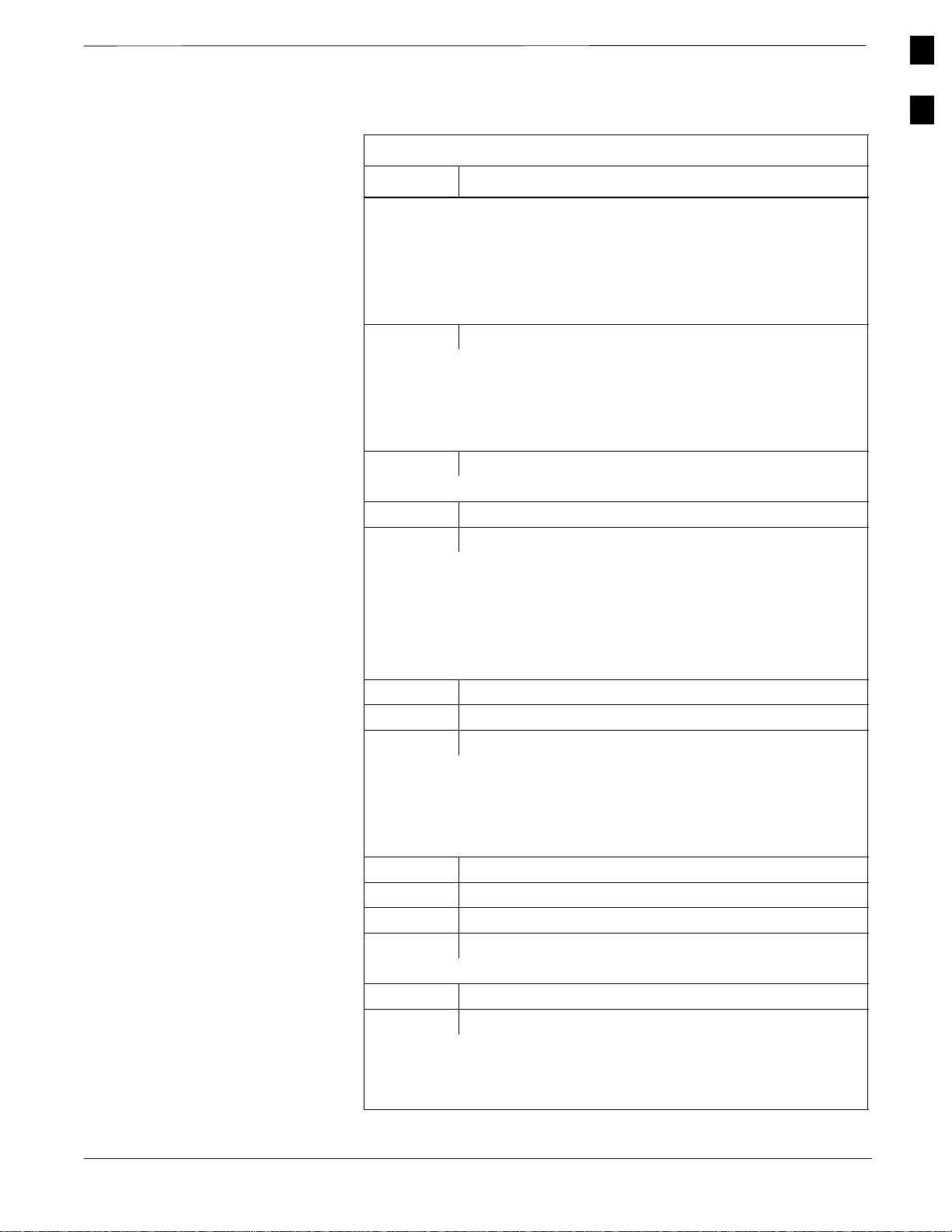
Table 1-2 shows the quantity and description of the installation hardware
that is shipped with the RF Cabinet and with the Power Cabinet.
Figure 1-1 is a template guide for identifying the parts.
Table 1-2: Installation Hardware Supplied with Cabinets
RF Power Description
1 1 7/16” Hex Tool
1 1 ESD Wrist Strap
4 4 Cabinet Mounting Brackets
8 8 M12 x 30 Bolts (for Mounting Brackets)
4 4 Insulating Shoulder Washer (for Mounting Bolts)
4 4 5/8” Bolts (to replace eye bolts)
1 1 Compression Lug (for #2 AWG Ground Wire)
2 2 M6 Stainless Steel Locking Hex Nuts (for Ground Lug)
4 4 M12 x 100 Bolt
4 16 M12 Flat Washer
4 4 M12 Lock Washer
4 4 M12 Nut
1 1 Motorola Ivory Touch–Up Paint
2 2 M6 Flat Washer
6 6 M10 Nut
6 6 M10 Flat Washer
6 6 M10 Lock Washer
4 4 5/8” Flat Washer
4 4 Large Flat Washer
1 – Weatherseal Bushing and Nut for RGPS Cable
1 – MMI Cable
– 12 Battery Terminal Straps
– 3 #2/0 AWG INS WELD Cable (Red)
– 3 #2/0 AWG INS WELD Cable (Black)
– 12 90° Compression Lug (for #2/0 AWG DC Cable)
– 1 Twisted Pair Cable (for Power Cabinet Alarms to RF Cabinet)
18
SCTM 4812ET RF and Power Cabinet Hardware Installation Manual
DRAFT
Apr 2001
V02.03
Page 19
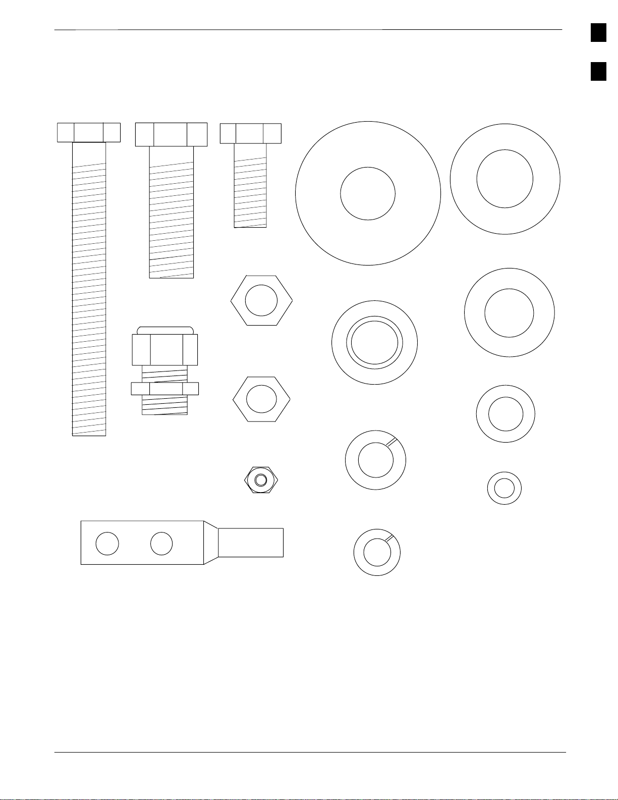
Figure 1-1: SC 4812ET Installation Hardware
Introduction
– continued
1
M12 X 100
5/8” BOLT
WEATHERSEAL
BUSHING & NUT
M12 X 30 BOLT
M12 NUT
M10 NUT
M6 NYLON
LOCKING NUT
LARGE FLAT
WASHER
INSULATION SHOULDER
WASHER
M12 LOCK
WASHER
5/8” FLAT
WASHER
M12 FLAT
WASHER
M10 FLAT
WASHER
M6 FLAT WASHER
Apr 2001
V02.03
COMPRESSION LUG (FOR
#2 AWG GROUND WIRE)
SCTM 4812ET RF and Power Cabinet Hardware Installation Manual
FW00468
M10 LOCK
WASHER
19
DRAFT
Page 20

1
Introduction
– continued
Recommended Tools
Table 1-3 lists tools recommended for installing RF and Power Cabinets.
Table 1-3: Recommended Tools
Item Tool Description
1 Tin Snips
2 Wire Brush
3 Knife or Scissors
4 10 mm Nut Driver
5 19 mm (3/4”) Open ended Torque Wrench (for N–type
connector)
6 110 Style Punch Block Termination Tool
7 Thomas & Betts TBM14 Hydraulic crimping tool with color
keyed crimp die set (or equivalent)
8 Drill Motor
9 18 mm (11/16”) Masonry Drill Bit
10 Ratchet Handle with 19 mm (3/4”) Socket (Deep Socket or
Ratchet Extension required).
11 Torque Driver (Torque Range: 5–135 N–m [4–100 ft–lbs])
with 19 mm (3/4”) and 10 mm Socket
12 Torque wrench for SMA’s Mountz Inc. MTBN2 (Part number
020314) with 5/16” open end head (Part number 020402).
13 Copper–based Conductive Grease (Berndy “Penetrox” or
equivalent).
20
SCTM 4812ET RF and Power Cabinet Hardware Installation Manual
DRAFT
Apr 2001
V02.03
Page 21

Materials Available from Motorola
Introduction
– continued
Table 1-4 lists tools and materials available from Motorola. The items
are identified by the Motorola assigned part number and include a brief
description. These items can be ordered from your sales account team.
Table 1-4: Cables, Tools, and Hardware
Material Part Number Description
CGDSRG142BU RG – 142 COAX by the foot
SGDN4232A 1/2” LDF Heliax by the foot
SGDN4234A 7/8” LDF Heliax by the foot
SGDN4235A 1–1/4” LDF Heliax by the foot
SGDN4233A 1–5/8” LDF Heliax by the foot
CGDSFSJ450B 1/2” Superflex Heliax by the foot
CGDSFSJ150A 1/4” Superflex Heliax by the foot
Cables
Tools
Hardware
CGTDN7023A Transmission Line Kit for 1/2”
LDF Heliax
CGTDN7025A Transmission Line Kit for 7/8”
LDF Heliax
CGTDN7027A Transmission Line Kit for 1–5/8”
LDF Heliax
CGDS241148 1/2” Superflex Jumper – 30 ft. (1
N Male terminated, 1 N Male
non–terminated)
CGDSICPVC25FT 25 Twisted pair cable – 24 AWG
CGDS237776 110 Punchdown Tool (Handle
only)
CGDS237176 Replacement Blade for use with
110 Punchdown Tool
CGDSTBM25S Crimp Tool for Compression Lug
CGDS97400036 Earthquake Expansion type An-
chor Bolt
1
Apr 2001
V02.03
SCTM 4812ET RF and Power Cabinet Hardware Installation Manual
DRAFT
21
Page 22
1
Introduction
– continued
Overview
The major components which make up the Motorola SC 4812ET RF
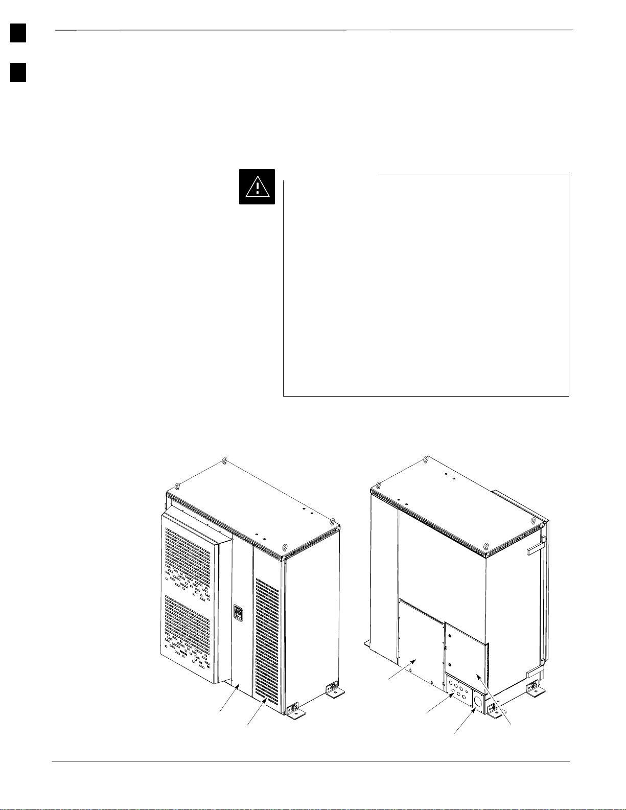
Cabinet (see Figure 1-2) and Power Cabinet (see Figure 1-7) system are
illustrated in this section.
CAUTION
A service tent [reference: Pelsue Cabinet Mounted Service
Tent; Pelsue (800–525–8460) P/N CM564866M] must be
in place prior to opening the main doors of the SC 4812ET
RF or Power Cabinet during times of inclement weather
(rain, snow, sleet, or hail). This will prevent moisture from
being drawn into the electronics by internal fans and
damaging the equipment.
A service tent [reference: Pelsue Cabinet Mounted Service
Tent; Pelsue (800–525–8460) P/N CM564866M] with a
heater is required to service the SC 4812ET RF Cabinet
when temperatures are below –10 degrees C (14 degrees
F). Temperatures inside the tent should be above 0 degrees
C (32 degrees F) prior to opening the main cabinet door.
This will prevent a rapid temperature change to the
electronics which could result in site outage.
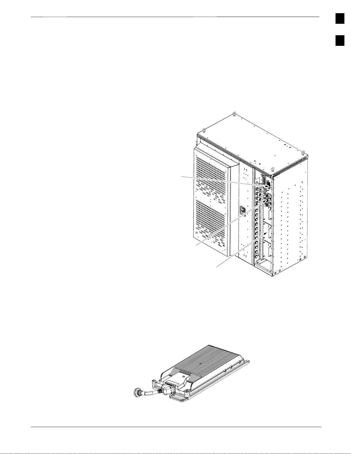
Figure 1-2: SC 4812ET RF Cabinet
Main Door
LPA Door
(Can only be opened after Main Door is open)
RF I/O
Area Cover Plate
Rear Conduit Panel
Rear DC Conduit Panel
Rear I/O Door
FW00189
22
SCTM 4812ET RF and Power Cabinet Hardware Installation Manual
DRAFT
Apr 2001
V02.03
Page 23
RF Cabinet External
FRUs
Figure 1-3: RF Cabinet External FRUs
Introduction
– continued
Figure 1-3 shows the location of the External Field Replaceable Units in
the RF Cabinet. A brief description of each External FRU is found in the
following paragraphs.
External Blower
Assembly (EBA)
1
Figure 1-4: SC4812ET LPA
Note:
LPA Compartment
door not shown for
clarity
LPA
Unpopulated LPA
Shelf Cover
FW00190
Linear Power Amplifier (LPA)
The LPA (See Figure 1-4) amplifies RF signals for transmission via the
antenna. The SC 4812ET can accommodate up to 16 LPA’s. The actual
number of LPA’s present depends upon RF Cabinet configuration.
Apr 2001
V02.03
FW00191
. . . continued on next page
SCTM 4812ET RF and Power Cabinet Hardware Installation Manual
DRAFT
23
Page 24
1
Introduction
– continued
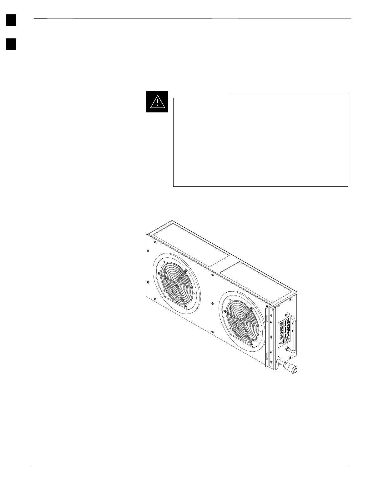
External Blower Assembly (EBA)
The External Blower Assembly (see Figure 1-5) is a modular unit that
provides cooling to the LPA’s, two blowers are used in the RF Cabinet.
Figure 1-5: External Blower Assembly (EBA)
CAUTION
The EBA contains two blowers and provides cooling that
is VITAL to prevent service outage and possible damage
to the LPAs. Since the SC 4812ET can continue to operate
normally with one functional blower in the EBA, the EBA
should not be removed until the replacement EBA is
onsite. Then, the EBA is replaced as a unit while the RF
cabinet is running. The replacement must be done within 3
minutes to prevent damage to the LPAs. Refer to the SC
4812ET FRU Guide for details regarding FRU
replacement.
24
FW00192
SCTM 4812ET RF and Power Cabinet Hardware Installation Manual
DRAFT
Apr 2001
V02.03
Page 25
RF Cabinet Internal FRUs
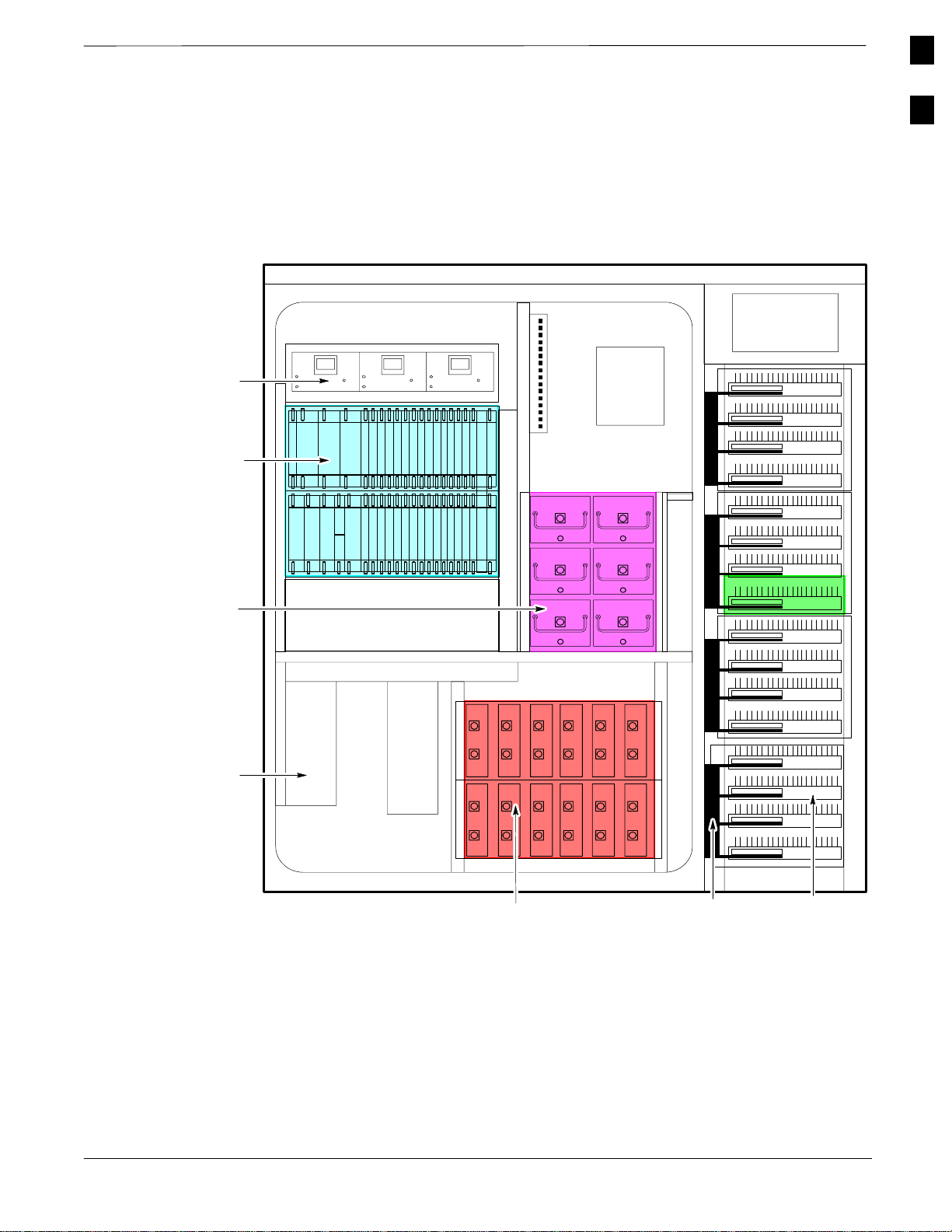
Figure 1-6: RF Cabinet Internal FRUs
Introduction
– continued
Figure 1-6 shows the location of the Internal Field Replaceable Units. A
brief description of each Internal FRU is found in the following
paragraphs.
1
CCP Fans
C–CCP Shelf
Combiner
Cage
Circuit
Breaker Panel
DC
Power
Dist.
5 RU Rack Space
OPTIONAL AREA
Punch
Block
(back)
ETIB
EBA
RFDS
Apr 2001
V02.03
DRDC/TRDC
LPA Trunking
Backplane
Duplexer/Directional Coupler (DRDC)
The DRDC combines, in a single module, the functions of antenna
duplexing, receive band pass filtering, and surge protection.
TX Filter/RX Filter/Directional Coupler (TRDC)
The TRDC is the same as the DRDC but has a separate antenna
connector for TX and RX operation. The TRDC is not available in the
1.9 GHz band.
. . . continued on next page
SCTM 4812ET RF and Power Cabinet Hardware Installation Manual
DRAFT
LPA’s
FW00163
25
Page 26

1
Introduction
– continued
Combiner Cage (2:1, 4:1, or Band pass Filter)
The Combiner Cage holds the transmit band pass filters, 2:1 combiners,
or 4:1 combiners, depending on system configuration.
Combined CDMA Channel Processor (C–CCP) Shelf
The C–CCP shelf contains the following:
S High Stability Oscillator (HSO)/LFR (Optional) card
S Clock Synchronization Manager (CSM) on 2 cards (one with GPS
receiver if ordered).
S CDMA Clock Distribution (CCD) cards (2)
S Power Supply cards (2 minimum, 3 maximum)
S Multicoupler Preselector Cards (MPC) (2)
S Alarm Monitoring and Reporting (AMR) cards (2)
S Multi Channel CDMA [MCC–1X (8E or 24), MCC–1X (8E/24)]
cards (up to 12)
S Broadband Transceiver (BBX–1X) cards (up to 13)
S Combined Input/Output (CIO) (1)
S Group Line Interface (GLI2) cards (2)
S BBX2 Switch card (1)
S Modem (optional)
S Filler Panels
S Fan Module (3)
Punch Block
The Punch Block is the interface point of the RF Cabinet between the
T1/E1 span lines, the Customer I/O, alarms, multi–cabinet timing
(RGPS and RHSO), and Pilot Beacon control (optional).
Span I/O Board
The Span I/O Board provides the interface for the span lines from the
CSU to the C–CCP backplane.
RF Diagnostic Subsystem (RFDS)
The RFDS provides the capability for remotely monitoring the status of
the SC 4812ET RF Transmit and Receive paths.
SC 4812ET Interface Board (ETIB) & LPA Control Brd (LPAC)
The ETIB is an interconnect board showing status LEDs for the RF
Cabinet, as well as providing secondary surge protection. The LPAC
board provides the interface for the LPA connection.
SC 4812ET Trunking Backplane
The Trunking Backplane contains a complex passive RF network that
allows RF signals to share the resources of a bank of four LPAs. It also
provides DC Power and digital interconnect.
26
SCTM 4812ET RF and Power Cabinet Hardware Installation Manual
DRAFT
Apr 2001
V02.03
Page 27

Power Cabinet
Figure 1-7: Power Cabinet
Introduction
– continued
Heat Exchanger
The Heat Exchanger provides cooling to the internal compartment of the
RF Cabinet. The fan speed of the heat exchangers adjusts automatically
with temperature. The Heat Exchanger is located in the primary front
door of the RF Cabinet.
Figure 1-7 illustrates the Power Cabinet design.
GFCI Outlet
Cover
1
Battery Door
Main Door
Rear I/O
Door
Rear DC
Conduit Panel
Rear AC Conduit
Panel
FW00193
Apr 2001
V02.03
SCTM 4812ET RF and Power Cabinet Hardware Installation Manual
DRAFT
27
Page 28
1
Introduction
– continued
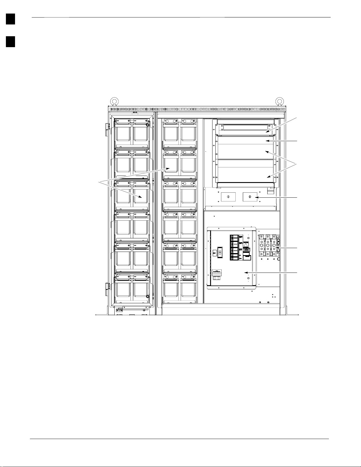
Power Cabinet Internal FRUs
Figure 1-8 shows the location of the Internal Field Replaceable Units.
The FRUs are described in the following paragraphs.
Figure 1-8: Power Cabinet with Batteries Installed (Doors Removed for Clarity)
Rectifier
Alarm
Module
Temperature
Control
Module
Rectifier
Batteries
(Battery
Heaters
located under
batteries)
Shelves
AC Outlet
Cover
NOTE
Punch Block
is not visible
in this view.
DC
Circuit
Breakers
AC
Load
Center
FRONT VIEW POWER CABINET
FW00164
Batteries
The batteries provide a +24V DC backup to the RF Cabinet should AC
Power be lost. The Power Cabinet can accommodate a total of 24 12V
batteries, configured in 12 strings of 2 batteries each. The time duration
of backup provided depends on system configuration.
Battery Heater
28
The battery heaters provide heating to the batteries in the Power Cabinet.
A separate heater is required for each string of batteries. The heater is a
pad the batteries sit on located top of each battery shelf. The number of
heaters is dependent on system configuration.
. . . continued on next page
SCTM 4812ET RF and Power Cabinet Hardware Installation Manual
DRAFT
Apr 2001
V02.03
Page 29

Introduction
– continued
Battery Compartment Fan
The battery compartment fan provides air circulation for the two battery
compartments. It is located on the inside of the battery compartment
door.
Heat Exchanger
The Heat Exchanger provides cooling to the rectifier compartment of the
Power Cabinet. The Heat Exchanger is located in the primary front door
of the Power Cabinet.
Rectifiers
The +27V rectifiers convert the AC power supplied to the Power Cabinet
to +27V DC to power the RF Cabinet and maintain the charge of the
batteries.
AC Load Center (ACLC)
The ACLC is the point of entry for AC Power to the Power Cabinet. It
incorporates AC power distribution and surge protection.
1
Enclosure Dimensions
Height Width Item Depth Weight (Max)
1677 mm
(66”)
1677 mm
(66”)
1423 mm
(56”)
1423 mm
(56”)
Punch Block
The Punch Block is the interface for the alarm signalling between the
Power Cabinet and the RF Cabinet.
Table 1-5 show the dimensions for the SC 4812ET RF and Power
Cabinet enclosures.
Table 1-5: Cabinet Dimensions
SC4812ET RF Cabinet
Power Cabinet
NOTE
The primary front door of the RF Cabinet and both front
doors of the Power Cabinet are removable. The depth of
the cabinets with the door(s) removed is 711 mm (28”).
915 mm
(36”)
965 mm
(38”)
680 kg
(1500 lbs)
1590 kg
(3500 lbs)
Apr 2001
V02.03
SCTM 4812ET RF and Power Cabinet Hardware Installation Manual
DRAFT
29
Page 30
1
Introduction
– continued
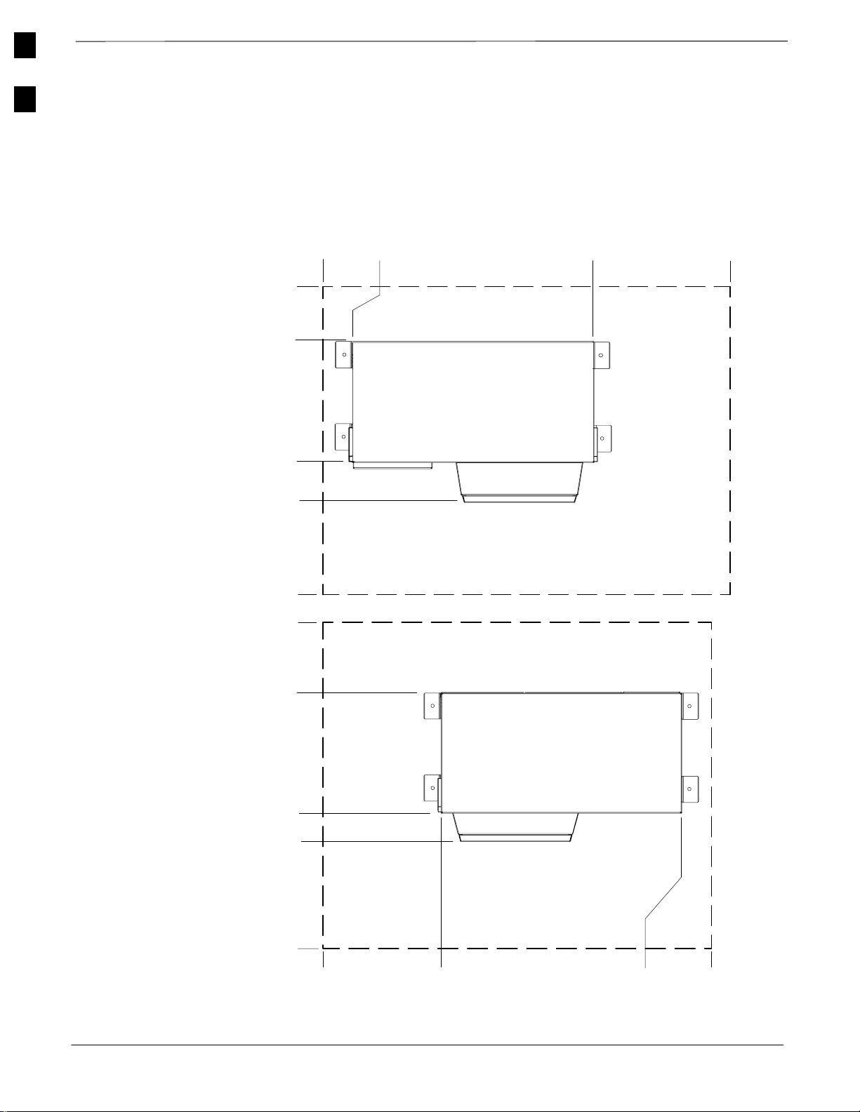
Enclosure Clearances
Figure 1-9 and Figure 1-10 show the clearances for the SC 4812ET RF
and Power Cabinet enclosures.
Figure 1-9: Minimum Cabinet Clearances for Door Openings and Mounting Brackets
0mm
(0I)
660mm
(26I)
1372mm
(54”)
1651mm
(65I)
2515mm
(99I)
0mm
(0I)
0mm
(0I)
130mm
(5I)
Power Cabinet
1550mm
(61I)
1880mm
(74I)
NOTE
Not To
Scale
30
510mm
(20I)
RF Cabinet
1220mm
(48”)
1421mm
(56I)
2363m
(93I)
0mm
(0I)
255mm
(10I)
1676mm
. . . continued on next page
SCTM 4812ET RF and Power Cabinet Hardware Installation Manual
DRAFT
(66I)
1803mm
(71I)
Apr 2001
FW00104
V02.03
Page 31

Figure 1-10: Minimum Site Clearances for SC 4812ET Cabinets
1143 mm
(45”)
130 mm
(5”)
Introduction
– continued
1
1143 mm
(45”)
Power
Cabinet
RF Cabinet
660 mm
(26”)
660 mm
(26”)
330 – 610 mm
(13” – 24”)
3430 – 3710 mm
(135 – 146”)
Apr 2001
V02.03
130 mm
2515 mm
(99”)
NOTE:
(1) 24” IS RECOMMENDED BETWEEN CABINETS TO ALLOW
SIMULTANEOUS OPENING OF CABINET DOORS
(2) BASED ON FIGURE 1–10 MOTOROLA RECOMMENDS A MINIMUM
PAD (OR PEDESTAL) SIZE OF 2515 MM (99”) BY 3710 MM (146”)
(5”)
SCTM 4812ET RF and Power Cabinet Hardware Installation Manual
DRAFT
FW00105
31
Page 32

1
Introduction
– continued
Notes
32
SCTM 4812ET RF and Power Cabinet Hardware Installation Manual
DRAFT
Apr 2001
V02.03
Page 33

This section includes...
2
Chapter 2: Site Preparation
Overview 34. . . . . . . . . . . . . . . . . . . . . . . . . . . . . . . . . . . . . . . . . . .
Indoor Location 34. . . . . . . . . . . . . . . . . . . . . . . . . . . . . . . . . . . . .
Rooftop Location 36. . . . . . . . . . . . . . . . . . . . . . . . . . . . . . . . . . . .
Cabinet Weight Table 36. . . . . . . . . . . . . . . . . . . . . . . . . . . . . . . . .
SC 4812ET RF Configuration 37. . . . . . . . . . . . . . . . . . . . . . . . . .
Minimum Battery Count for Power Cabinet 42. . . . . . . . . . . . . . .
Outdoor Location 42. . . . . . . . . . . . . . . . . . . . . . . . . . . . . . . . . . . .
Materials Needed 43. . . . . . . . . . . . . . . . . . . . . . . . . . . . . . . . . . . .
Existing Concrete Pad Mounting 46. . . . . . . . . . . . . . . . . . . . . . . .
Drilling Introduction 47. . . . . . . . . . . . . . . . . . . . . . . . . . . . . . . . . .
Drilling Procedure 47. . . . . . . . . . . . . . . . . . . . . . . . . . . . . . . . . . .
Rooftop 49. . . . . . . . . . . . . . . . . . . . . . . . . . . . . . . . . . . . . . . . . . . .
Rooftop (Elevated) 50. . . . . . . . . . . . . . . . . . . . . . . . . . . . . . . . . . .
New Concrete Pad 50. . . . . . . . . . . . . . . . . . . . . . . . . . . . . . . . . . .
Connection Materials 51. . . . . . . . . . . . . . . . . . . . . . . . . . . . . . . . .
Concrete Pad and Ground System Installation 51. . . . . . . . . . . . . .
RGPS Mounting Considerations 57. . . . . . . . . . . . . . . . . . . . . . . .
Apr 2001
V02.03
Tables
Table 2-1: DC Cabling Size – Maximum Cable Length 36. . . . . .
Table 2-2: Approximate Weight of SC 4812ET BTS 37. . . . . . . . .
Table 2-3: SC 4812ET FRU Configurations – Duplexed 38. . . . . .
Table 2-4: SC 4812ET FRU Configurations – Non–Duplexed 38.
Table 2-5: Min Battery Strings Required Sector–Carrier Configs 42
Table 2-6: Heliax Cable Loss and Minimum Bend Radii 44. . . . .
Table 2-7: Number of wires in Conduit 44. . . . . . . . . . . . . . . . . . .
Table 2-8: Drilling Procedure 47. . . . . . . . . . . . . . . . . . . . . . . . . . .
Table 2-9: Concrete Pad & Ground System Install Procedure 52. .
Figures
Figure 2-1: Drill Stabilization 48. . . . . . . . . . . . . . . . . . . . . . . . . .
Figure 2-2: Mounting Hole Drilling and Cleaning 49. . . . . . . . . . .
. . . continued on next page
SCTM 4812ET RF and Power Cabinet Hardware Installation Manual
DRAFT
33
Page 34

Site Preparation
– continued
Figure 2-3: Grounding Ring Detail 53. . . . . . . . . . . . . . . . . . . . . .
Figure 2-4: Conduit Stub Height Detail 53. . . . . . . . . . . . . . . . . . .
2
Overview
Figure 2-5: Cabinet Dimensions 54. . . . . . . . . . . . . . . . . . . . . . . . .
Figure 2-6: Pad Forms and Conduit Layout 55. . . . . . . . . . . . . . . .
Figure 2-7: Mounting Hole Dimensions 55. . . . . . . . . . . . . . . . . . .
Figure 2-8: SC 4812ET RF Cabinet Conduit I/O 56. . . . . . . . . . . .
Figure 2-9: SC 4812ET Power Cabinet Conduit I/O 57. . . . . . . . .
This chapter covers the SC 4812ET BTS site preparation recommended
guidelines.
Installation sites can be classified into one of the three following
categories: Indoor, Rooftop or Outdoor.
All applications will have common requirements and considerations.
Differences between the location site requirements will be covered
throughout the installation section. The following information is meant
to serve as a guideline and can be impacted by site specific
considerations.
Indoor Location
WARNING
Every effort should be made to provide a safe working area
for all installation and service personnel.
CAUTION
The mounting surface must be flat. Door closure problems
may occur if the cabinets are not installed on a flat surface.
IMPORTANT
*
The following items should be considered when choosing an indoor
location for the SC 4812ET BTS:
– A permanent location is more desirable than a temporary one.
– The cabinets should be placed in a location with appropriate
Care should be taken to ensure that the AC power pedestal
does not interfere with the future addition of expansion or
optional equipment service area.
clearance from any obstructions. For minimum clearances see
Chapter 1.
. . . continued on next page
34
SCTM 4812ET RF and Power Cabinet Hardware Installation Manual
DRAFT
Apr 2001
V02.03
Page 35

Site Preparation
– continued
– Adequate ventilation must be available to dissipate heat loads of
7,500 Watts (25,600 Btu / hr) for the RF Cabinet and 3,000 Watts
(10,300 Btu / hr) for the Power Cabinet (a total of 10,500 Watts;
35,900 Btu / hr), and maintain a maximum temperature of no
greater than 50 Deg C (122 Deg
– The AC meter and main disconnect should not be mounted to either
cabinet.
– Locations should be selected that will minimize accidental or
intentional vandalism. Do not select a location that is, or may be,
subject to submersion (i.e. diversion channels, sub–basements, etc).
While the RF and Power Cabinet are well insulated from the
environment, they will not tolerate submersion.
– There should be adequate clearance through doors and passageways
to allow movement of the cabinet from the delivery area to the
installation site.
– Verify, prior to final site selection, the availability and accessibility
to good grounding (ground system resistance must be less than 10
Ohms, with 5 Ohms or less being the goal; see ”Recommended
Documentation” for Grounding Guidelines), RF cabling, Telco
wiring, and 208–240 VAC power.
– There should be adequate space available for the future addition of
expansion or optional equipment.
– The location of an AC power pedestal to mount the AC meter, main
breaker, generator plug, etc. (if necessary), is at the installers option.
– Every effort should be made to minimize the separation distance
between the RF and Power Cabinet (see Table 2-1) for maximum
cable length between cabinets
F).
2
Table 2-1: DC Cabling Size – Maximum Cable Length
Cable Size Resistance per 1,000 ft @ 50Deg C
mW (THHN Cable)
2/0 AWG 96.8 (Superflex) 6.7 m (22 ft)
4/0 AWG 54 (Duraflex) 12.5 m (41 ft)
Maximum Cable Length
(Max Total Voltage Drop 0.4V,
assumes 90A per cable)
NOTE
– 3.65 m (12 ft.) is the length of the # 2/0 AWG DC Power Cable supplied with the Power Cabinet.
– If a custom cable is used, 610 mm (2 ft.) should be reserved at both ends to allow for the distance from the
edge of the cabinet to the power terminals.
Apr 2001
V02.03
SCTM 4812ET RF and Power Cabinet Hardware Installation Manual
DRAFT
35
Page 36

Site Preparation
– continued
Rooftop Location
In addition to the Indoor location considerations, the following
2
additional items should be considered when choosing a Rooftop
location:
WARNING
Roof load carrying limits must be reviewed and an
appropriate support structure must be installed to support
the cabinets as required.
CAUTION
The cabinets must be elevated sufficiently above the roof
surface to prevent water from puddling around its base.
Although the cabinets are well insulated from the
environment they will not tolerate submersion.
Loading Considerations (also see Table 2-2):
– A single SC 4812ET RF Cabinet can weigh up to 680 kg. (1500
lbs) and a single Power Cabinet enclosure can weigh up to 1590 kg.
(3500 lbs) with the batteries installed (batteries are shipped
separately). Expansion enclosures and optional equipment will add
weight (refer to the introduction section of this manual for obtaining
detailed information on the optional equipment).
NOTE
The Power Cabinet as shipped without batteries installed
can weigh up to 544 kg (1200 lbs.).
– When the cabinet is to be roof mounted, be sure to consider the rain
and/or snow loading of the region when determining whether the
roof can support the load.
Zoning requirements – that relate to building mounted equipment
should be checked for any restrictions that may affect cabinet or antenna
placement.
Adequate clearance through doors, passageways and stairwells to allow
movement of the cabinet from the delivery area to the installation site.
Cabinet Weight Table
36
SCTM 4812ET RF and Power Cabinet Hardware Installation Manual
Minimum separation distance – Every effort should be made to
minimize the separation distance between the RF and Power Cabinet
(see Table 2-1).
Table 2-2 lists the approximate weight of both the RF and Power
cabinets in various site configurations.
. . . continued on next page
Apr 2001
DRAFT
V02.03
Page 37

Table 2-2: Approximate Weight of SC 4812ET BTS
Site Preparation
– continued
# of Sectors
– Carriers
1
RF Cabinet
2
Power Cabinet
3
Total Weight Weight/Area Total Weight Weight/Area
3 570 kg (1260 lbs) 563 kg/m
6 610 kg (1340 lbs) 602 kg/m
9 644 kg (1420 lbs) 636 kg/m
12 680 kg (1500 lbs) 671 kg/m
2
(0.8 psi) 1015 kg (2240 lbs) 1002 kg/m
2
(0.85 psi) 1206 kg (2660 lbs) 1192 kg/m
2
(0.91 psi) 1400 kg (3080 lbs) 1383 kg/m
2
(0.95 psi) 1590 kg (3500 lbs) 1571 kg/m
2
2
2
2
NOTE
1
To obtain this number, multiply the number of sectors and the number of carriers present (i.e., 3 sector, 3
carrier is 9 sector–carriers)
2
Assumes 12 DRDCs present in cabinet
3
Assumes 4 hours of battery backup and maximum battery weight of 41 kg (90 lbs) each.
SC 4812ET RF FRU
Configuration
SC 4812ET FRU Configurations for Duplexed sites are described in
Table 2-3 (see page 38).
(1.84 psi)
(1.7 psi)
(2.0 psi)
(2.2 psi)
2
SC 4812ET FRU Configurations for Non–Duplexed sites are described
in Table 2-4 (see page 39).
Apr 2001
V02.03
SCTM 4812ET RF and Power Cabinet Hardware Installation Manual
DRAFT
37
Page 38

Site Preparation
– continued
Con–
3 Sector
6 Sector
Ttl #
fig
car
car
car
car
car
car
car
car
Sec
Car
1
2
3
4
5
6
7
8
VH
LPAs
3 4 1 3 3 opt 3 opt 6 6
6 8 2 3 3 opt 3 opt 6 6
9 12 3 3 3 3 opt 6 6
12 16 4 NA 6 3 opt 6 6
15 16 4 NA NA 3
18 16 4 NA NA 3
21 16 4 NA NA 3
24 16 4 NA NA 3
Trnk
Mod
Table 2-3: SC 4812ET FRU Configurations – Duplexed
BTS 1 – Starter BTS 2 – Expansion
4812
DBPF
4812
Cmbr
2:1
4812
4:1
Cmbr
DRDCs
6 (3
opt)
6 (3
opt)
6 (3
opt)
6 (3
opt)
Dplxd
AntsVHLPAs
3 4 1 3 3 opt 3 opt 3 3
3 8 2 NA 3 opt 3 opt 3 3
3 12 3 NA 3 3 3 3
3 16 4 NA 3 3 3 3
Trnk
Mod
4812
DBPF
Cmbr
4812
2:1
4812
4:1
Cmbr
DRDCs
Dplxd
Ants
Expansion Field Recabling
Add Tx cable trunking module
to DBPF/conbiner.
Add Tx cable trunking module
to DBPF/ combiner. Recable
Starter Tx to add combiners
Add Tx cable trunking module
to combiner. Recable Starter Tx
to add combiners
Recable Starter Tx to add
combiners, recable Starter Rx,
cable Rx exp. between frames,
& move 3 antennas to exp.
Add Tx cable trunking module
to DBPF/combiner. Recable
Exp Tx to add combiners
Add Tx cable trunking module
to combiner
Add Tx cable trunking module
to combiner
Expansion
Impact to
Service
None
Take down
ALL Tx
Take down
Carrier 3
Tx
Take down
diversity
Rx and
ALL Tx.
Take down
Carrier 5
Tx
Take down
Carriers 5
and 6 Tx
None
38
1
car
car
car
6 8 2 6 6–opt NA 12 12
2
12 16 4 6 6–opt NA 12 12
3
18 16 4 NA 6 NA
SCTM 4812ET RF and Power Cabinet Hardware Installation Manual
12(6–
opt)
6 8 2 6 6–opt NA 6 6
Add Tx cable trunking module
to DBPF/combiner
Recable Starter Tx to add
combiners, recable Starter Rx,
cable Rx exp between frames,
and move 6 antennas to exp.
. . . continued on next page
DRAFT
None
Take down
diversity
Rx and
ALL Tx
Page 39

Table 2-3: SC 4812ET FRU Configurations – Duplexed
Ttl #
Con–
Con–
Ttl #
Sec
Sec
fig
fig
Car
Car
8
car
4
car
NOTES: Tx combiners typicalln not used until system exceeds 2 carriers.
VH
LPAs
24 16 4 NA 6 NA
Duplexed diversity Rx antennas are routed to DRDCs in expansion frame and then diversity Rx expansion is routed back to starter frame.
Tx paths are NOT routed between expansion and starter frames (i.e. each frame must have its own Tx antennas which reduces loss).
When expansion frame is added, the unused DRDCs in the starter frame could be removed and replaced with cover plates, but it is not recommended due to the time involved.
Trnk
Mod
4812
DBPF
4812
Cmbr
2:1
4812
4:1
Cmbr
3NANA41624
DRDCs
6 (3
opt)
12(6–
opt)
Table 2-4: SC 4812ET FRU Configurations – Non–Duplexed
BTS 1 – Starter BTS 2 – Expansion
4812
DBPF
4812
Cmbr
2:1
4812
4:1
Cmbr
TRDCs
RX
Ant
Con–
fig
3 Sector
1
car
2
car
3
car
4
car
Ttl #
Sec
Car
VH
LPAs
3 4 1 3 3 opt 3 opt 6 6 3
6 8 2 3 3 opt 3 opt 6 6
9 12 3 NA 6 3 opt 6 6
12 16 4 NA 6 3 opt 6 6
Trnk
Mod
BTS 2 – ExpansionBTS 1 – Starter
2:1
4812
2:1
Cmbr
4812
4:1
Cmbr
4812
4:1
Cmbr
DRDCs
TRDCs
Dplxd
Ants
VH
LPAs
6 16 4 NA 6 NA 6 6
TX
AntVHLPAs
6 (3
opt)
6 (3
opt)
6 (3
opt)
Mod
DBPF
Trnk
Mod
4812
Trnk
4812
Cmbr
4812
DBPF
Dplxd
Ants
3333NA4163
RX
AntTXAnt
Site Preparation
Expansion Field Recabling
Expansion Field Recabling
Add Tx cable trunking module
to combiner
Add Tx cable trunking module
to combiner. Recable Exp Tx to
add combiners
Expansion Field
Recabling
Add Tx cable trunking
module to
DBPF/conbiner.
Add Tx cable trunking
module to DBPF/
combiner. Recable
Starter Tx to add
combiners
Add Tx cable trunking
module to combiner.
Recable Starter Tx to
add combiners
. . . continued on next page
– continued
Expansion
Expansion
Impact to
Impact to
Service
Service
None
Take
dowm
Carrier 3
Tx
Expansion
Impact to
Service
None
Take down
ALL Tx
Take down
Carrier 3
Tx
Apr 2001
SCTM 4812ET RF and Power Cabinet Hardware Installation Manual
39
DRAFT
Page 40

Site Preparation
– continued
Ttl #
Con–
Con–
6 Sector
Ttl #
Sec
Sec
fig
fig
Car
Car
LPAs
5
15 16 4 NA NA 3
car
6
18 16 4 NA NA 3
car
7
21 16 4 NA NA 3
car
8
24 16 4 NA NA 3
car
1
car
6 8 2 6 6 opt NA 12 12 6
VH
Trnk
Mod
4812
DBPF
4812
2:1
Cmbr
Table 2-4: SC 4812ET FRU Configurations – Non–Duplexed
BTS 2 – ExpansionBTS 1 – Starter
4812
4:1
Cmbr
TRDCs
6 (3
opt)
6 (3
opt)
6 (3
opt)
6 (3
opt)
RX
Ant
3
3
3
3
TX
Ant
3 (6
opt)
3 (6
opt)
3 (6
opt)
3 (6
opt)
VH
LPAs
4 1 3 3 opt 3 opt 3 3 3
8 2 NA 3 opt 3 opt 3 3 3
12 3 NA 3 3 3 3 3
16 4 NA 3 3 3 3 3
Mod
DBPF
4812
Trnk
4812
Cmbr
2:1
4812
4:1
Cmbr
TRDCs
RX
Ant
Expansion Field
TX
Ant
Expansion Field
Recabling
Recabling
Recable Starter Tx to
add combiners, recable
Starter Rx, cable Rx exp.
between frames, & move
3 antennas to exp.
Add Tx cable trunking
module to
DBPF/combiner. Recable
Exp Tx to add combiners
Add Tx cable trunking
module to combiner
Add Tx cable trunking
module to combiner
Expansion
Expansion
Impact to
Impact to
Service
Service
Take down
diversity
Rx and
ALL Tx.
Take down
Carrier 5
Tx
Take down
Carriers 5
and 6 Tx
None
40
2
12 16 4 6 opt 6 NA 12 126(12
car
3
18 16 4 NA 6 NA
car
4
24 16 4 NA 6 NA
car
12(6–
12(6–
SCTM 4812ET RF and Power Cabinet Hardware Installation Manual
opt)
opt)
opt)
6 6 8 2 6 opt 6 NA 6 6 6
6 6 16 4 NA 6 NA 6 6 6
DRAFT
Add Tx cable trunking
module to DBPF/
combiner. Recable
Starter Tx to add
combiners.
Recable Starter Tx to
add combiners, recable
Starter Rx, cable Rx exp
between frames, and
move 6 antennas to exp.
Add Tx cable trunking
module to combiner.
Recable Exp Tx to add
combiners
. . . continued on next page
None
Take down
diversity
Rx and
ALL Tx
Take
dowm
Carrier 3
Tx
Page 41

Table 2-4: SC 4812ET FRU Configurations – Non–Duplexed
Ttl #
Con–
Con–
Ttl #
Sec
Sec
fig
fig
Car
Car
8
car
NOTES: Tx combiners typically not used until system exceeds 2 carriers.
VH
LPAs
Duplexed diversity Rx antennas are routed to TRDCs in expansion frame and then diversity Rx expansion is routed back to starter frame.
Tx paths are NOT routed between expansion and starter frames (i.e. each frame must have its own Tx antennas which reduces loss).
When expansion frame is added, the unused TRDCs in the starter frame could be removed and replaced with cover plates, but it is not recommended due to the time involved.
Trnk
Mod
4812
DBPF
4812
Cmbr
2:1
4812
4:1
Cmbr
3NANA41624
TRDCs
6 (3
opt)
RX
Ant
Site Preparation
– continued
BTS 2 – ExpansionBTS 1 – Starter
Expansion Field
Expansion Field
Recabling
Recabling
Add Tx cable trunking
module to combiner
2:1
4812
4:1
Cmbr
TRDCs
RX
Ant
TX
Ant
33333NA416
TX
LPAs
Ant
3 (6
3
opt)
Mod
DBPF
4812
Trnk
VH
4812
Cmbr
Expansion
Expansion
Impact to
Impact to
Service
Service
None
Apr 2001
SCTM 4812ET RF and Power Cabinet Hardware Installation Manual
41
DRAFT
Page 42

Site Preparation
– continued
Minimum Battery Count for
2
Power Cabinet
Table 2-5 lists the number of Battery strings required for the different
sector–carrier configurations and the backup power time provide by the
various combinations.
Table 2-5: Minimum Battery Strings Required for Sector–Carrier Configurations
# of
Battery
Strings
0 0 0 0 0
1
2
3
4
5
6 4.0 hrs
7 4.8 hrs 3.5 hrs
8 5.4 hrs 4.0 hrs
9 6.0 hrs 4.5 hrs 3.6 hrs
10 6.7 hrs 5.0 hrs 4.0 hrs 3.3 hrs
11 7.4 hrs 5.5 hrs 4.4 hrs 3.6 hrs
12 8.0 hrs 6.0 hrs 4.8 hrs 4.0 hrs
3 Rectifiers
(3 Sector–Carriers)
4 Rectifiers
(6 Sector–Carriers)
5 Rectifiers
(9 Sector–Carriers)
6 Rectifiers
(12 Sector–Carriers)
! CAUTION
The minimum number of battery strings presented in this table must be met or reduced backup time and
inadvertant tripping of the battery system breakers could result.
Outdoor Location
42
NOTE
The backup durations presented within this table is an
estimated time based on 25 Deg C (77Deg F) battery
temperature, actual backup duration may vary with system
configuration and loading.
CAUTION
Do not select a location that is, or may be subject to
submersion (i.e., floodplains, diversion channels, etc.).
While the cabinets are well insulated from the
environment, they will not tolerate submersion.
SCTM 4812ET RF and Power Cabinet Hardware Installation Manual
DRAFT
Apr 2001
Page 43

Site Preparation – continued
In addition to the Indoor location considerations, the following
additional items should be considered when choosing an outdoor
location:
– The cabinet should be placed in a location with appropriate
clearance from any obstructions. For minimum clearances see
Chapter 1.
– It should be the practice of any installing company to acquire, in
advance of construction, the rights of way from landowners, and
permits or approvals from public authorities. It is recommended that
the BTSs be placed in servitudes, on dedicated (recorded)
easements, or on property owned by the company. Unrecorded
easements should be avoided.
– The cabinet should be easily accessible with adequate parking to
ensure craftsmen and vehicle safety. Also, place the cabinet where it
will not create a visual or physical obstruction to either vehicular or
pedestrian traffic.
– Locations should be selected that will minimize accidental or
intentional vandalism. The use of protective posts and/or fences
should be considered when located near parking areas where
vehicles may hit the cabinet.
– Every effort should be made to minimize the separation distance
between the RF and Power Cabinet (see Table 2-1).
2
Materials Needed
The following list of materials may vary depending on site specific
requirements. If in doubt contact Motorola Cellular Support Center. The
phone number is found in the Foreword of this manual.
Installation hardware is provided with the cabinets. (Refer to Chapter 1
for a description of this hardware).
Tools – Refer to Chapter 1 for a list of tools that will be helpful when
installing the SC4812ET BTS.
RF Transmission Lines
– Cables are 12.7 mm (1/2”), 22.2 mm (7/8”), 31.8 mm (1–1/4”) or
41.3 mm (1–5/8”) Foam
See Table 2-6 for dB Loss per foot and minimum bending radius.
– Either 102 mm (4”) or 152 mm (6”) conduit, depending on size of
Heliax (see Table 2-7), is recommended.
R
Heliax, depending on dB loss budget.
Apr 2001
SCTM 4812ET RF and Power Cabinet Hardware Installation Manual
DRAFT
43
Page 44

Site Preparation – continued
NOTE
It may not be necessary or desirable to run the transmission
2
Table 2-6: Heliax Cable Loss and Minimum Bend Radii
lines in any conduit at all. In this case the transmission
lines should be protected from falling objects (i.e., ice,
etc.) or from being stepped on.
Heliax Motorola Part
Heliax
Cable
RG 142 CGDSRG142BU .49 .66 .15 .20 10 mm .4”
3/8” LDF N/A .115 .167 .035 .051 95 mm 3–3/4”
1/2”LDF SGDN4232A .0768 .1132 .0234 .0345 125 mm 5”
1/2” FSJ4 N/A .119 .177 .0363 .0541 13.75 mm 1.25”
7/8”LDF SGDN4234A .0430 .0646 .0131 .0197 250 mm 10”
1–1/4”LDF SGDN4235A .0317 .0476 .00967 .0145 380 mm 15”
1–5/8”LDF SGDN4233A .0269 .0410 .00819 .0125 510 mm 20”
Motorola Part
No.
dB loss per meter dB loss per foot Min. bend radius
@ 1 GHz @ 2 GHz @ 1 GHz @ 2 GHz Metric U.S.
NOTE
As an additional rule of thumb, allow 0.1 dB additional loss for each connection point.
Table 2-7: Number of wires in Conduit
Conduit
Conduit
Trade Size
2” 5 2 1 – –
2–1/2” 7 3 1 – –
3” 11 5 3 – –
4” 19 9 5 1 1
6” 20 20 12 3 2
9.5 mm (3/8”) 12.7 mm (1/2”) 21.4 mm (7/8”) 31.8 mm (1–1/4”) 41.3 mm (1–5/8”)
Foam Heliax Trade Size (Cable Type LDF)
* IMPORTANT
The values listed above were calculated based on the percent of conduit cross–section filled and recommended
limits set forth by Andrew Corporation. These limits are based on common conditions or proper cabling and
alignment of conductors where the length of pull and the number of bends are within reasonable limits. It
should be recognized that for certain conditions a larger size conduit or a lessor fill should be considered.
Power Cabinet AC Power Connection
208–240 VAC – Flexible Liquid Tight Conduit is recommended.
44
SCTM 4812ET RF and Power Cabinet Hardware Installation Manual
Apr 2001
DRAFT
Page 45

Site Preparation – continued
IMPORTANT
*
The AC power pedestal or meter should be provided with a breaker to
protect the cable from the pedestal to the Power Cabinet. The Power
Cabinet rating is 130Amp. A 150–amp breaker is recommended, or as
appropriate for local electrical code.
The Power Cabinet is rated at 130 Amps (100 Amps
continuous / 130 Amps non–continuous, in the range of
208–240V AC, see Table 5-32 for details). Maximum
cable size that can be accommodated is 300 kc mil.
Cabling sizing should be determined by Local Electrical
Codes, using 90Deg C rated conductors, and derated for
50 Deg C operation. Motorola recommends not less than
#2/0 AWG (#1 BSWG; 50 mm
buried/raceway cables to the power pedestal, with an
associated power pedestal breaker size of 150 Amps for
one Power Cabinet.
NOTE
The knockout in the I/O plate of the Power Cabinet is the
proper size for a 2” Trade size conduit fitting.
2
) copper for
2
Ground Wire Connection (RF and Power Cabinet) – #3 B.S.W.G (#2
AWG; 35 mm
RF Cabinet Alarm Cable Connection
– Sixteen (16) twisted pair cable
– 25.4 mm (1”) conduit (maximum)
RF Cabinet Span and Modem Cable Connection
– Thirteen (13) twisted pair cable
– 25.4 mm (1”) conduit (maximum)
Main RF Cable – 50 Ohm Coaxial, male N–type connector on one end,
customer specific on other end.
RGPS Cable (if applicable) – See Table 5-1 for cable specifications
RF GPS Cable (if applicable) – See Table 5-1 for cable specifications
LFR Cable (if applicable) – See Table 5-1 for cable specifications
2
) solid–tinned copper wire or equivalent is recommended
. . . continued on next page
Apr 2001
SCTM 4812ET RF and Power Cabinet Hardware Installation Manual
DRAFT
45
Page 46

Site Preparation – continued
Power Cabinet Alarm Cable – A Twelve (12) wire, Six (6) twisted pair
cable [Cable supplied with the Power Cabinet is 4.5 m (15 ft) in length].
2
DC Power Interconnect
– #1 BSWG (#2/0 AWG; 50 mm2) insulated weld wire or equivalent
is recommended (supplied with the Power Cabinet)
– 51 mm (3”) conduit
Existing Concrete Pad
Mounting
NOTE
Custom cable lengths are available from Storm Products
(214–637–1381); 9215 Premier Row, Dallas, TX. 75247.
Part number “070197–6SA” for Non–Plenum rated cable.
NOTE
The DC Power Cabling and the Power Cabinet Alarm
Cable can be run in the same 3” Conduit from the RF
Cabinet to the Power Cabinet.
CAUTION
The mounting surface must be flat. Door closure problems
may occur if the BTS is not installed on a flat surface.
For an installation where the cabinet will mount flush to an existing
concrete floor, all of the connections to the cabinet will be made through
the rear I/O area of the cabinet. For this reason, the cabinet must be set
in place and bolted down prior to running any conduits or wiring.
Conduit/wire routing will be discussed in Chapter 5.
Lightning protection is provided with the cabinet. A good earth ground
(ground system resistance must be less than 10 Ohms, with 5 Ohms or
less being the goal), is required for the lightning protection equipment to
perform properly. Refer to Motorola’s guidelines (Motorola Publication
68P81150E62) for details on the design of a grounding system. Conform
to local electrical construction standards for conduit materials and sizing.
46
SCTM 4812ET RF and Power Cabinet Hardware Installation Manual
DRAFT
Apr 2001
Page 47

Site Preparation – continued
Drilling Introduction
The following includes steps that must be followed to safely drill the
mounting holes. Check the mounting hardware to be used to make sure
you use the correct drill bit sizes.
CAUTION
Motorola recommended anchor bolts (Motorola P/N
CGDS97400036) must be used to assure safety in the
event of an earthquake.
WARNING
Safety glasses, dust masks, and ear plugs must be worn by
all installation personnel, including those in the immediate
vicinity of personnel operating the drill equipment.
2
Drilling Procedure
Before beginning, read the following steps in their entirety to familiarize
yourself with the procedure.
Table 2-8: Drilling Procedure
Step Action
After the cabinet position has been established, the mounting hole location can be marked using the
1
dimensions supplied in Figure 2-5, by using the 1:1 installation template supplied in Appendix G, or
by placing the cabinet over the desired location and tracing the mounting hole locations.
NOTE
– Motorola recommended anchor bolts require 18 mm (11/16”) drill size.
n W ARNING
– Always wear safety glasses, dust masks, ear plugs, and proper attire when using power equipment.
Remove any loose jewelry and tuck shoe laces into work boots.
. . . continued on next page
Apr 2001
SCTM 4812ET RF and Power Cabinet Hardware Installation Manual
DRAFT
47
Page 48

Site Preparation – continued
Table 2-8: Drilling Procedure
Step Action
2
Position the end of the drill bit in the center of the first mark on the floor. Stabilize the drill by holding
2
the drill handle at the 90_ position, refer to Figure 2-1. Rest the drill against your leg while drilling to
counter the drill’s tendency of rotating out of your hand while drilling through reinforcement bars and
stone aggregate.
Figure 2-1: Drill Stabilization
POSITION
DRILL BIT IN
CENTER OF
MARK ON
FLOOR
90 Degree
_
PLACE KNEE NEXT TO
DRILL
TO CONTROL ROTATION
POSITION WORK
BOOT NEXT TO BIT
WHEN STAR TING TO
PREVENT BIT FROM
WALKING.
3 Begin to drill in short bursts, keep the drill bit from “walking” by using the side of your work boot to
hold the drill in place until drill “has a bite” in the concrete. Once started, run drill at full speed.
. . . continued on next page
48
SCTM 4812ET RF and Power Cabinet Hardware Installation Manual
DRAFT
Apr 2001
Page 49

Site Preparation – continued
Table 2-8: Drilling Procedure
Step Action
Have a second installer turn on the shop vacuum and place the nozzle near the hole to collect dust and
4
debris (see Figure 2-2). This will extend the life of the drill bit, and give you a better idea of how deep
the hole is. Wrapping a piece of electrical tape around the drill bit to indicate the desired depth is
suggested.
Figure 2-2: Mounting Hole Drilling and Cleaning
AIR GUN USED TO CLEAR
DEBRIS FROM MOUNTING
HOLE
TAPE WRAPPED
AROUND BIT TO
INDICA TE DEPTH
2
VACUUM USED TO
COLLECT DEBRIS
WHILE DRILLING/
CLEANING HOLES
5 Repeat Step 3 and 4 for all remaining holes to be drilled for this cabinet.
6 Clean all holes by using the shop vacuum in conjunction with the air compressor gun attachment.
Begin by using short bursts of air several inches away from the hole, gradually decreasing the distance
from the hole while increasing the duration of the air bursts until the hole is completely free of loose
material.
Rooftop
WARNING
Roof load carrying limits must be reviewed and an
appropriate support structure must be installed to support
the RF and Power Cabinet as required.
CAUTION
The cabinet must be elevated sufficiently above the roof
surface to prevent water from puddling around its base.
Although the cabinets are well insulated from the
environment they will not tolerate submersion.
. . . continued on next page
Apr 2001
SCTM 4812ET RF and Power Cabinet Hardware Installation Manual
DRAFT
49
Page 50

Site Preparation – continued
Refer to Figure 2-5 and Figure 2-6 for proper position of mounting
locations when designing the support structure.
2
Rooftop (Elevated)
New Concrete Pad
For most rooftop installations all of the connections to the cabinet will
be made through the rear of the cabinet I/O area. For this reason, the
cabinet must be set in place and bolted down prior to running any
conduits or wiring. Conduit/wire routing will be discussed in Chapter 5.
Lightning protection is included in the cabinet. A good earth ground
(ground system resistance must be less than 10 Ohms, with 5 Ohms or
less being the goal) is required for the lightning protection equipment to
perform properly. Refer to Motorola’s guidelines (Motorola Publication
68P81150E62) for details on the design of a grounding system. Conform
to local electrical construction standards for conduit materials and sizing.
For a rooftop installation which is elevated sufficiently above the roof
surface, most of the connections can be made through the bottom of the
cabinet by terminating the conduit at the bottom of the rear I/O area. See
Figure 2-6 for recommended conduit/cable entrance layout.
CAUTION
The mounting surface must be flat. Door closure problems
may occur if the cabinets are not installed on a flat surface.
To help reduce the chance of damage caused by lightning
strikes, it is required that a ground ring be constructed
when the pad is built. See section titled ”Ground System
Installation”.
50
Variations in pad construction methods may be required to comply with
local conditions, practices, or building codes.
Install the grounding system, and electrical conduits (see Figure 2-3,
Figure 2-4, and Figure 2-6) prior to pad construction. Refer to the
Motorola guidelines (Motorola Publication 68P81150E62) for details on
the design of a grounding system. Conform to local electrical
construction standards for conduit materials and sizing. Refer to
Table 2-6 and Table 2-7 for minimum bend radius of antenna cables and
maximum number of cables in a conduit.
If it is desired to make cabling through the bottom of the cabinets, it is
recommended that the conduits be positioned using the dimensions
given in Figure 2-5 prior to pouring the concrete pad. Installation in this
manner allows for the connections to the RF and Power Cabinet to be
made through the bottom of the I/O area, although it may be desirable to
make the antenna connections through the rear wall. For the connections
that are made through the bottom of the I/O area, conduits and wiring
can be installed prior to arrival of the cabinet.
. . . continued on next page
SCTM 4812ET RF and Power Cabinet Hardware Installation Manual
DRAFT
Apr 2001
Page 51

Site Preparation – continued
Connection Materials
CAUTION
Conduits that are pre–installed in a concrete pad below
grade must be capped at the time of conduit installation to
prevent rainwater from collecting in the conduit.
WARNING
If a precast concrete foundation pad is used, the pad should
be in place before the cables are installed. This will avoid
an unsafe condition caused by personnel reaching under a
pad, as it is lowered, to feed cable through the pad
openings.
This section defines connection materials and specifications and may
vary depending on site–specific requirements. If in doubt, contact
Motorola Cellular Support Center (telephone number is found in the
Foreword of this manual).
2
Concrete Pad and Ground
System Installation
The following procedure describes the concrete pad ground system
installation. The following steps are meant to serve as a guideline and
can be impacted by the local codes of the installation site location.
Materials Needed:
CADWELD Joints
8–12 – ground wire to ground rod joints (for 2–6 cabinets)
4 – rebar joints
1 – ground wire to rebar joint
Ground Rods - 8–12 – 5/8” Diameter, 2438 mm (96”) long ground
rods (for 2–6 cabinets)
Framing Materials – This list of materials is used to form the pad.
– No. 66–44 wire mesh, or 9.5 mm (3/8”) rebar, sized to fit the pad
– Concrete (Must conform to ASTMC94, specification for ready mix
concrete)
Apr 2001
NOTE
It is recommended that the concrete pad maintain a
minimum thickness of 102 mm (4 inches) or the length of
the anchor bolt to be used, whichever is greater.
SCTM 4812ET RF and Power Cabinet Hardware Installation Manual
DRAFT
51
Page 52

Site Preparation – continued
Installation Procedure:
Install the concrete pad and ground system as described in Table 2-9.
2
Step Action
1 Ensure that the pad location is firm and level. If the ground around the location is not firm, compact
the soil and construct a level base for the pad using a minimum of six inches of gravel or per local
code requirements.
2 Dig trenches 610 mm (24”) deep (minimum), and wide enough to accommodate the ground ring and
conduits.
3 Install conduits. Recommended locations are shown in Figure 2-6. Refer to Table 2-6, and Table 2-7
for minimum bend radius of Foam Heliax and maximum number of Heliax in a conduit.
4 Install 152 mm (6”) concrete pad frame with integral rebars and dry wells. Refer to Figure 2-6 for pad
dimensions.
5 Install #3 BSWG (#2 AWG; 35 mm2) solid tinned copper perimeter ground ring (see Figure 2-3).
6 Exothermic weld #3 BSWG (#2 AWG; 35 mm2) solid tinned copper wire from concrete pad rebar to
perimeter ground ring.
7 Install copper clad steel ground rods.
8 Exothermic weld perimeter ground ring to steel ground rods.
9 Install three #3 BSWG (#2 AWG; 35 mm2) solid tinned copper wires, exothermic welded to perimeter
ground ring, for BTS master ground, Power Cabinet master ground, and for antenna tower ground
straps.
Table 2-9: Concrete Pad and Ground System Installation Procedure
NOTE
For sites with multiple cabinets an additional #3 BSWG (#2 AWG; 35 mm2) solid tinned copper wire
must be installed for each additional cabinet.
10 Fill the trenches in the area of the pad with soil and tamp.
11 Pour concrete until level or slightly above the concrete forms. Puddle the concrete along the edges of
the forms. Use a straight piece of lumber or equivalent as a guide to level the concrete.
12 For additional finishing, wait until the pad no longer looks as if water is standing on top and trowel
smooth.
13 After the second day the concrete forms can be removed.
14 The concrete mounting pad must cure adequately before the cabinets may be installed.
. . . continued on next page
52
SCTM 4812ET RF and Power Cabinet Hardware Installation Manual
DRAFT
Apr 2001
Page 53

Site Preparation – continued
Figure 2-3: Grounding Ring Detail
GROUNDING RING #3 BSWG
(#2 AWG;35 mm2) SOLID
COPPER W/TIN COATING
Grounding Ring:
The following information details installation of the site grounding ring.
Refer to Figure 2-3 for detail dimensions.
GROUND TO CABINET (1 PER CABINET) #3 BSWG
(#2 AWG;35 mm2) SOLID COPPER W/TIN COATING
2438 mm (96”)
GROUND
RODS (8–12)
2
609 mm
(2’ 0”)
GROUND TO ANTENNA
#3 BSWG (#2 AWG; 35
mm2) SOLID COPPER
W/TIN COATING
609 mm
(2’ 0”)
609 mm
(2’ 0”)
GROUND TO CABINET (1 PER CABINET) #3 BSWG (#2
AWG;35 mm2) SOLID COPPER W/TIN COATING
FRONT
609 mm
(2’ 0”)
GROUND TO REBAR
(CADWELD)
REBAR JOINTS
(CADWELD) (4)
REBAR
10 mm (3/8”)
MINIMUM.
CONCRETE
PAD
Figure 2-4: Conduit Stub Height Detail
Apr 2001
SCTM 4812ET RF and Power Cabinet Hardware Installation Manual
CONDUIT STUBS ARE
TO BE 25 TO 50 MM (1”
TO 2”) ABOVE
CONCRETE PAD.
CONCRETE
PAD
NOTE
– Conduits that are Pre–installed must be capped to
prevent moisture from collecting prior to cabinet
installation.
– Used when I/O goes through the bottom of the
cabinet I/O area, i.e. when conduit is set in concrete
pad or floor.
53
DRAFT
Page 54

Site Preparation – continued
Figure 2-5: Cabinet Dimensions
2
102 mm
(4”)
POWER CABINET
365 mm
(15”)
1425 mm
(56”)
455 mm
(18”)
102 mm
(4”)
605 mm
(24”)
711 mm
(28”)
1030 mm
(41”)
270 mm
(11”)
54
711 mm
1060 mm
(42”)
205 mm
(8”)
(28”)
RF CABINET
1425 mm
(56”)
341 mm
(14”)
FW00106
SCTM 4812ET RF and Power Cabinet Hardware Installation Manual
DRAFT
Apr 2001
Page 55

Site Preparation – continued
Figure 2-6: Pad Forms and Conduit Layout
49 mm
(1.9”)
973 mm
(38.3)
1470 mm
1289 mm
(50.7”)
2
49 mm
(57.9”)
(1.9”)
145 mm
(5.7”)
1471 mm
(57.9”)
61 mm
(2.4”)
16 mm
(0.6”)
87 mm
(3.4”)
475 mm
(18.7”)
614 mm
(24.2”)
0
0
867 mm
(34.2”)
1158 mm
(45.6”)
1188 mm
(46.7”)
1390 mm
(54”)
1518 mm
(59.8”)
0
14 mm
(0.5”)
0
89 mm
(3.5”)
527 mm
(20.7”)
587 mm
1518 mm
(23”)
1091 mm
(42.9”)
(59.8”)
–65 mm
(–2.5”)
5 mm
(0.2”)
77 mm
(3”)
Power Cabinet RF Cabinet
DC (TO RF
CABINET)
DC (TO POWER
CABINET)
GROUND
MAIN AC
AC (TO PILOT
BEACON)
RF CABINET)
Figure 2-7: Mounting Hole Dimensions
Apr 2001
475 mm
(18.7”)
SCTM 4812ET RF and Power Cabinet Hardware Installation Manual
DC (TO
PILOT BEACON
DC (TO POWER
1518 mm
(59.8”)
CABINET)
SPAN/ALARM
EXPANSION 1
EXPANSION 2
GROUND
Note:
Hole Pattern is
Identical for RF and
Power Cabinets
DRAFT
EXPANSION RF
MAIN RF
FW00005
55
Page 56

Site Preparation – continued
Figure 2-8: SC 4812ET RF Cabinet Conduit I/O
2
415 mm
(16.3”)
340 mm
(13.3”)
0 mm
(0”)
650 mm
(25.5”)
595 mm
(23.4”)
469 mm
(18.5”)
261 mm
(10.3”)
0 mm
(0”)
1069 mm
(42.1”)
70 mm
(2.8”)
75 mm
(3.0”)
629 mm
(24.7”)
587 mm
(23.1”)
65 mm
(2.6”)
304 mm
(11.9”)
65 mm
(2.6”)
133 mm
(5.2”)
272 mm
(10.6”)
49 mm
(1.9”)
0 mm
(0”)
211 mm
(8.3”)
139 mm
(5.4”)
104 mm
(4.1”)
67 mm
(2.6”)
0 mm
(0”)
FW00194
56
SCTM 4812ET RF and Power Cabinet Hardware Installation Manual
DRAFT
Apr 2001
Page 57

Site Preparation – continued
Figure 2-9: SC 4812ET Power Cabinet Conduit I/O
2
217 mm
(8.5”)
82 mm
(3.2”)
0 mm
(0”)
RGPS Mounting
Considerations
0 mm
(0”)
49 mm
(1.9”)
230 mm
(9”)
FW00195
446 mm
(17.5”)
546 mm
(21.4”)
The RGPS Head requires specific mounting considerations in order to
properly observe the GPS satellites.
– The mounting pipe for the RGPS Head should be mounted
vertically with less than five degrees of tilt.
– The RGPS Head needs to have a clear view of the sky, preferably to
within ten degrees of the horizon in all directions. The less sky that
can be observed the fewer the number of potential satellites that can
be tracked and hence the poorer the RGPS performance.
– For general operation, the RGPS Head needs to be able to
continuously track signals from at least four (4) GPS satellites. It is
theoretically possible to operate the BTS with only one GPS
satellite visible, however, operating in this mode it is not
recommended and requires an accurate site survey.
Apr 2001
SCTM 4812ET RF and Power Cabinet Hardware Installation Manual
DRAFT
57
Page 58

Site Preparation – continued
– Place the RGPS Head where RF obstructions of the sky are
minimized. The “sky” includes everything to within ten degrees
(10°) of the horizon in all directions. RF obstructions includes
2
buildings, towers, snow, foliage and debris.
– Separate the RGPS Head from radiating sources. Excessive RF
energy can degrade the RGPS head’s ability to observe the GPS
satellites. The RGPS head receives on the GPS L1 frequency of
1575.42 MHz and has filters incorporated within to minimize the
effects of potential RF interference, however, strong radiators can
overwhelm the filters, thus degrading the units reception capability.
– The RGPS Head is rated for ambient air temperatures from –40 Deg
C to +50 Deg C, and has ratings for Humidty, Shock, Waterproof,
UV Light Resistance, Vibrations, Salt, Fog, ESD, EMI, and
Altitude.
– The RGPS system will support up to 2000 feet (610 m) of overall
cable length from the RGPS Head to the last connected base station.
If a long cable run needs to be broken into pieces, minimize the
number of breaks in the cable.
58
SCTM 4812ET RF and Power Cabinet Hardware Installation Manual
DRAFT
Apr 2001
Page 59

This section includes...
Chapter 3: How to Unpack the SC 4812ET BTS
3
Unpacking the SC 4812ET BTS 59. . . . . . . . . . . . . . . . . . . . . . . . .
Materials Needed 59. . . . . . . . . . . . . . . . . . . . . . . . . . . . . . . . . . . .
Order of Unpacking 60. . . . . . . . . . . . . . . . . . . . . . . . . . . . . . . . . .
Equipment Identification 60. . . . . . . . . . . . . . . . . . . . . . . . . . . . . .
Overview 61. . . . . . . . . . . . . . . . . . . . . . . . . . . . . . . . . . . . . . . . . . .
How the Cabinet is Shipped 61. . . . . . . . . . . . . . . . . . . . . . . . . . . .
How to Unpack a Cabinet 62. . . . . . . . . . . . . . . . . . . . . . . . . . . . . .
Unpack Procedure 62. . . . . . . . . . . . . . . . . . . . . . . . . . . . . . . . . . . .
How to Inspect for Damage 66. . . . . . . . . . . . . . . . . . . . . . . . . . . .
How to Inspect Equipment for Damage 66. . . . . . . . . . . . . . . . . . .
Tables
Table 3-1: Unpacking Cabinet (Wood Shipping Crate) 62. . . . . . .
Unpacking the SC 4812ET
BTS
Materials Needed
Table 3-2: Unpacking Cabinet (Cardboard Shipping Carton) 63. .
Table 3-3: Inspecting Cabinets for Damage 66. . . . . . . . . . . . . . . .
Figures
Figure 3-1: SC 4812ET RF Cabinet 60. . . . . . . . . . . . . . . . . . . . . .
Figure 3-2: SC 4812ET Power Cabinet 61. . . . . . . . . . . . . . . . . . .
Figure 3-3: Wood Shipping Crate 64. . . . . . . . . . . . . . . . . . . . . . . .
Figure 3-4: Cardboard Shipping Carton 65. . . . . . . . . . . . . . . . . . .
This chapter provides the procedures necessary to identify, unpack, and
inspect the equipment for damage.
– Tin Snips
– Knife or Scissors
Apr 2001
V03.03
SCTM 4812ET RF and Power Cabinet Hardware Installation Manual
DRAFT
59
Page 60

How to Unpack the SC 4812ET BTS
– continued
Order of unpacking
The unpacking process requires that the following procedures be
completed in the order shown:
1. Identify the equipment
2. Unpack the RF Cabinet
3. Unpack the Power Cabinet
3
Equipment Identification
Figure 3-1: SC 4812ET RF Cabinet
4. Inspect the equipment for damage
Use Figure 3-1 and Figure 3-2 to visually identify the SC 4812ET RF
and Power Cabinet, respectively.
60
SCTM 4812ET RF and Power Cabinet Hardware Installation Manual
DRAFT
Apr 2001
V03.03
Page 61

Figure 3-2: SC 4812ET Power Cabinet
How to Unpack the SC 4812ET BTS
– continued
3
Overview
How the Cabinet is Shipped
The purpose of this section is to describe how the SC 4812ET RF and
Power Cabinets are packaged for shipping and how to correctly unpack
the cabinets in preparation for installation.
The cabinets are packed standing up in either cardboard or wood cartons
(see Figure 3-3 and Figure 3-4). The RF Cabinet is shipped fully
assembled and all internal cabling installed. The Power Cabinet is
shipped without the batteries installed.
Apr 2001
V03.03
SCTM 4812ET RF and Power Cabinet Hardware Installation Manual
DRAFT
61
Page 62

How to Unpack the SC 4812ET BTS
– continued
How to Unpack a Cabinet
WARNING
– The steel bands surrounding the carton can spring out
from the carton when the bands are cut. To avoid
personal injury, stand safely to the side of the bands
3
while cutting.
– A fully loaded RF Cabinet can weigh up to 635 Kg
(1400 lbs), and a Power Cabinet as shipped (without
the batteries installed) can weigh up to 544 kg (1200
lbs).
– If a cabinet is tipped more than 10 inches from
vertical, it is in danger of tipping over. Handle with
extreme caution to avoid tipping.
Unpack Procedure
CAUTION
Do NOT lift or attempt to move the RF or Power Cabinet
by the doors, they will not support this type of loading and
may be damaged in the process.
Wood Shipping Crate
Use Table 3-1 to properly unpack the RF and Power Cabinet if the wood
shipping create was used.
Table 3-1:Unpacking a Cabinet (Wood Shipping Crate)
Step Action
1 Inspect the crates and cartons for damage. (Refer to
Figure 3-3).
NOTE
It is recommended that two (2) people perform this procedure.
62
2 Loosen the latches on the bottom of the crate.
3 Remove the clips holding the top piece of wood, and remove
the top piece of the crate.
4 Remove the clips holding the side pieces of wood, and
remove the sides of the crate.
. . . continued on next page
SCTM 4812ET RF and Power Cabinet Hardware Installation Manual
DRAFT
Apr 2001
V03.03
Page 63

How to Unpack the SC 4812ET BTS
– continued
Table 3-1:Unpacking a Cabinet (Wood Shipping Crate)
Step Action
5 Using appropriate lifting device, remove cabinet from bottom
pallet.
6 Immediately inspect the equipment for damage, (see
Table 3-3) and report the extent of any damage to the
transport company and to the appropriate
engineering/management personnel.
Cardboard Shipping Carton
Use Table 3-2 to properly unpack the RF and Power Cabinet if the
cardboard shipping carton was used.
Table 3-2:Unpacking a Cabinet (Cardboard Shipping Carton)
Step Action
3
1 Inspect the cartons for damage. (Refer to Figure 3-4).
NOTE
It is recommended that two (2) people perform this procedure.
2 Using tin snips, cut each outer steel band that surrounds the
carton.
3 Lift off cardboard carton.
4 Using appropriate lifting device, remove cabinet from bottom
pallet.
5 Immediately inspect the equipment for damage, (see
Figure 3-4) and report the extent of any damage to the
transport company and to the appropriate
engineering/management personnel.
Apr 2001
V03.03
SCTM 4812ET RF and Power Cabinet Hardware Installation Manual
DRAFT
63
Page 64

How to Unpack the SC 4812ET BTS
– continued
Figure 3-3: Shipping Crate (Wood)
3
64
SCTM 4812ET RF and Power Cabinet Hardware Installation Manual
DRAFT
Apr 2001
V03.03
Page 65

Figure 3-4: Cardboard Shipping Carton
How to Unpack the SC 4812ET BTS
– continued
3
Apr 2001
V03.03
SCTM 4812ET RF and Power Cabinet Hardware Installation Manual
DRAFT
65
Page 66

How to Unpack the SC 4812ET BTS
– continued
How to Inspect for
Damage
Before installing any equipment, inspect it for damage as described in
Table 3-3. Report any damage found to the appropriate supervisory
personnel.
WARNING
3
How to Inspect Equipment for
Damage
Step Action
1 Inspect the exterior of the RF and Power Cabinet for:
2 Inspect the interior of the RF and Power Cabinet for:
– Static sensitive equipment requires the use of ESD
protective gear such as a wriststrap to be used during
the installation and repair.
– A wriststrap is supplied with the installation hardware
and the ESD jack is located in the C–CCP Shelf in
the RF Cabinet (Figure 1-6).
Table 3-3: Inspecting Cabinets for Damage
– Dents
– Scratches
– Squareness of the cabinet.
– Bent FRU brackets
– Dislodged FRUs
– Cables that may have become disconnected.
66
3 Report any damage found to the appropriate supervisory
personnel.
SCTM 4812ET RF and Power Cabinet Hardware Installation Manual
DRAFT
Apr 2001
V03.03
Page 67

This section includes...
Chapter 4:Cabinet Mounting
Overview 68. . . . . . . . . . . . . . . . . . . . . . . . . . . . . . . . . . . . . . . . . . .
Removing the Front Doors (Optional) 68. . . . . . . . . . . . . . . . . . . .
Existing Concrete Pad Mounting Procedure 69. . . . . . . . . . . . . . .
Rooftop (Elevated Substructure) Mounting Procedure 71. . . . . . .
New Concrete Pad Mounting 72. . . . . . . . . . . . . . . . . . . . . . . . . . .
Battery and Heater Pad Installation 73. . . . . . . . . . . . . . . . . . . . . .
Installing Batteries in the Power Cabinet 76. . . . . . . . . . . . . . . . . .
Tables
Table 4-1: Removing Front Cabinet Doors 68. . . . . . . . . . . . . . . .
Table 4-2: Concrete Pad Mounting 69. . . . . . . . . . . . . . . . . . . . . . .
Table 4-3: Rooftop (Elevated Substructure) Mounting 72. . . . . . .
Table 4-4: New Concrete Pad Mounting 73. . . . . . . . . . . . . . . . . .
Table 4-5: Installing a Battery Heater Pad 75. . . . . . . . . . . . . . . . .
Table 4-6: Installing a String of Batteries 76. . . . . . . . . . . . . . . . . .
Table 4-7: Materials Required for Battery Cabling 77. . . . . . . . . .
Table 4-8: Power Cabinet Battery Cabling 77. . . . . . . . . . . . . . . . .
4
Apr 2001
V04.03
Figures
Figure 4-1: Front Cabinet Door Hinge 69. . . . . . . . . . . . . . . . . . . .
Figure 4-2: Cabinet Mounting Brackets 70. . . . . . . . . . . . . . . . . . .
Figure 4-3: Mounting Bolt Configuration 71. . . . . . . . . . . . . . . . .
Figure 4-4: Battery Heater Pad 74. . . . . . . . . . . . . . . . . . . . . . . . . .
Figure 4-5: Typical 12V Battery 76. . . . . . . . . . . . . . . . . . . . . . . . .
Figure 4-6: Power Cabinet – Batteries Installed, Doors Removed 78
Figure 4-7: Partial Cross–Section View of Battery Compartment 79
SCTM 4812ET RF and Power Cabinet Hardware Installation Manual
DRAFT
67
Page 68

Cabinet Mounting
– continued
Overview
Removing the Front Doors
(Optional)
This chapter covers the step–by–step instructions for mounting the RF
and Power Cabinet.
CAUTION
Do NOT lift or move the RF or Power Cabinet by the
doors, they will not support this type of loading and may
be damaged in the process.
WARNING
4
To facilitate the movement of the RF or Power Cabinet through
doorways or passageways with limited clearance, the front doors of the
cabinets can be removed. The procedure to do this is detailed in
Table 4-1.
Table 4-1: Procedure to Remove the Front Cabinet Doors (if required)
Step Action
1 Open the primary front door.
2 Disconnect the Heat Exchanger Power and Alarm cables from
3 For each hinge, loosen the screw that secures the door to the
4 Remove the windstay latch at the bottom of the door.
5 Lift the door straight up off the hinges.
Do Not remove the front cabinet doors unless absolutely
required.
the Heat Exchanger.
hinge (See Figure 4-1).
! CAUTION
The front door of both the RF and Power Cabinet can weigh
up to 77 kg (170 lbs). Use extreme care when handling to
avoid damage to the door, heat exchanger, and gasket.
68
6 Repeat for the battery cabinet door of the Power Cabinet if
required.
SCTM 4812ET RF and Power Cabinet Hardware Installation Manual
DRAFT
Apr 2001
V04.03
Page 69

Figure 4-1: Front Cabinet Door Hinge (Close-up View)
Cabinet Mounting
Loosen this screw to remove door
(Top and Bottom Hinges)
– continued
4
Existing Concrete Pad
Mounting Procedure
Mounting the cabinet on a pre–existing concrete pad requires that the
mounting holes be drilled using the procedures in Chapter 2 of this
manual. Follow the procedures in Table 4-2 to mount each cabinet.
Table 4-2: Concrete Pad Mounting
Step Action
1 Fasten mounting brackets (see Figure 4-2) onto cabinet with
M12 bolts (supplied in installation hardware). Do NOT torque
the bolts yet. Align the cabinet over the mounting holes.
! CAUTION
Do NOT use the cabinet doors as a hand hold to move the
cabinet around, this could damage the door hinges
2 Install the anchor bolts in the four (4) mounting locations in
the mounting brackets attached to the cabinet base. Tighten
the bolts to proper torque recommended by the manufacturer.
n W ARNING
Motorola recommended anchor bolts must be used to assure
safety in the event of an earthquake (CGDS97400036). These
bolts should be tightened to 80 N–m (60 ft–lbs.).
Apr 2001
V04.03
3 Tighten the M12 bolts attaching the mounting brackets to the
cabinet, torque to 135 N–m (100 ft–lbs) with a 19mm (3/4”)
torque wrench.
. . . continued on next page
SCTM 4812ET RF and Power Cabinet Hardware Installation Manual
DRAFT
69
Page 70

Cabinet Mounting
– continued
Table 4-2: Concrete Pad Mounting
Step Action
4 Remove the four (4) eye–bolts (see Figure 4-2) on the top of
the cabinet, replace them with the bolts and washers supplied
with the installation hardware using a 24 mm (15/16”) hex
driver. Torque to 80 N–m (60 ft–lbs).
5 Install the wiring as described in Chapter 5 of this manual.
NOTE
The isolation washers supplied in the hardware installation
kit are provided to give the installer the option of
4
electrically isolating the cabinet should the situation
require it. The use of the washers is not a requirement.
The grounding of each site is unique, and the isolation of
the cabinet is a site specific decision.
Figure 4-2: Cabinet Mounting Brackets
Eye–Bolt
70
NOTE
Use supplied M12 washers when fastening the mounting
brackets to the cabinet.
. . . continued on next page
SCTM 4812ET RF and Power Cabinet Hardware Installation Manual
DRAFT
Apr 2001
V04.03
Page 71

Figure 4-3: Mounting Bolt Configuration
CONCRETE PAD
LARGE FLAT WASHER
ANCHOR BOLT
CGDS97400036
CONCRETE
Cabinet Mounting
– continued
MOUNTING BRACKET
ISOLATION PAD
4
ROOFTOP
Rooftop (Elevated
Substructure) Mounting
Procedure
MOUNTING
STRUCTURE
(I–BEAM)
M12 X 100 BOLT
SMALL FL AT WASHER
SMALL FLAT
WASHER
M12 NUT
INSULATING WASHER
(OPTIONAL)
LARGE FLAT WASHER
MOUNTING BRACKET
ISOLATION PAD
LOCK WASHER
Mounting the cabinet on a rooftop requires that the roof load carrying
support structure be in place prior to mounting the cabinet. See Chapter
2, “Site Preparation” for details.
Apr 2001
V04.03
WARNING
Roof load carrying limits must be reviewed and an
appropriate support structure must be installed to support
the RF and Power Cabinet as required.
Once the support structure is in place, follow the procedures in Table 4-3
to mount the cabinet.
. . . continued on next page
SCTM 4812ET RF and Power Cabinet Hardware Installation Manual
DRAFT
71
Page 72

Cabinet Mounting
– continued
Table 4-3: Rooftop (Elevated Substructure) Mounting
Step Action
1 Fasten mounting brackets (see Figure 4-2) onto cabinet with
M12 bolts and washers (supplied in installation hardware).
Do NOT torque the bolts yet.
! CAUTION
Do NOT use the cabinet doors as a hand hold to move the
cabinet around, this could damage the door hinges
2 Place the cabinet on top of the substructure, so that the mounting
holes are aligned with the holes in the cabinet mounting
brackets.
4
3 Install the mounting bolts into the four (4) mounting locations
in the mounting brackets attached to the cabinet bast. Tighten
the bolts to the proper torque recommended by the
manufacturer of the bolts. If using the M12 bolts supplied
with the installation hardware, tighten the bolts to 80 N–m (60
ft–lbs.) torque.
4 Tighten the M12 bolts attaching the mounting brackets to the
cabinet. Torque to 135 N–m (100 ft–lbs) within a 19 mm
(3/4”) torque wrench
5 Remove the four (4) eye–bolts (see Figure 4-2) on the top of
the cabinet, replace them with the bolts and washers supplied
with the installation hardware using a 24 mm (15/16”) hex
driver. Torque to 80 N–m (60 ft–lbs).
6 Install the wiring as described in Chapter 5 of this manual.
NOTE
The isolation washers supplied in the hardware installation
kit are provided to give the installer the option of
electrically isolating the cabinet should the situation
require it. The use of the washers is not a requirement.
The grounding of each site is unique, and the isolation of
the cabinet is a site specific decision.
New Concrete Pad Mounting
72
SCTM 4812ET RF and Power Cabinet Hardware Installation Manual
Mounting the cabinet on a new concrete pad which has been designed to
install the cabinet offers some unique opportunities, as the cables, wires,
and conduits can all be routed into the cabinet from the bottom through
the concrete pad.
After the pad has been poured following the procedure in Chapter 2, the
concrete has cured adequately and the mounting holes drilled as detailed
in Chapter 2, follow the procedures in Table 4-4 to install each cabinet.
. . . continued on next page
Apr 2001
DRAFT
V04.03
Page 73

Cabinet Mounting
– continued
Table 4-4: New Concrete Pad Mounting
Step Action
1 Fasten mounting brackets (see Figure 4-2) onto the cabinet
with M12 bolts and washers (supplied in installation
hardware). Do NOT torque bolts yet. Align the cabinet over
the holes.
! CAUTION
Do NOT use the cabinet doors as a hand hold to move the
cabinet around, this could damage the door hinges
2 Install the anchor bolts in the four (4) mounting locations in
the mounting brackets attached to the cabinet base. Tighten
the bolts to proper torque recommended by the manufacturer.
n W ARNING
Motorola recommended anchor bolts must be used to assure
safety in the event of an earthquake (CGDS97400036). These
bolts should be tightened to 80 N–m (60 ft–lbs.).
4
Battery and Heater Pad
Installation
3 Tighten the M12 bolts attaching the mounting brackets to the
cabinet, torque to 135 N–m (100 ft–lbs) with a torque wrench.
4 Remove the four (4) eye–bolts (see Figure 4-2) on the top of
the cabinet, replace them with the bolts and washers supplied
with the installation hardware using a 24 mm (15/16”) hex
driver, torque to 80 N–m (60 ft–lbs).
5 Install the wiring as described in Chapter 5 of this manual.
NOTE
The isolation washers supplied in the hardware installation
kit are provided to give the installer the option of
electrically isolating the cabinet should the situation
require it. The use of the washers is not a requirement. The
grounding of each site is unique, and the isolation of the
cabinet is a site specific decision.
This section covers the step–by–step instructions for mounting the
batteries and heater pads into the Power Cabinet. The Power Cabinet
can accommodate a total of 12 strings of 2 batteries (24 batteries total)
and 12 heater pads (1 per battery string). The actual number of battery
strings and heaters installed depends upon system configuration. This
section reviews the procedure to install one (1) string of batteries and 1
heater pad. This should be repeated until all batteries and heaters are
installed.
. . . continued on next page
Apr 2001
V04.03
SCTM 4812ET RF and Power Cabinet Hardware Installation Manual
DRAFT
73
Page 74

Cabinet Mounting
– continued
NOTE
Batteries and heater pads in the Power Cabinet MUST be
installed in the bottom slots of the battery compartments
and building up. The first string should be installed in
“position 1” (see Figure 4-6), the second in “position 2”
and so on, until all batteries are installed. The heater pad
power cables are ”daisy–chained” from the bottom in each
battery compartment (see Figure 4-7). The last (top) heater
pad cable must be terminated with a connector that is
shipped installed on the cable located in the bottom slot of
each battery compartment (positions 1 and 2).
4
Battery Heater Installation
Table 4-5 reviews the procedure to install a battery heater pad. This
procedure should be repeated until all heater pads are installed.
NOTE
ALL heater pads should be installed and cables properly
dressed before ANY batteries are installed.
Figure 4-4: Battery Heater Pad
Rear
Bottom
74
Top
Front
NOTE
Bottom side of the Heater Pad has adhesive liners that
must be removed prior to installation.
. . . continued on next page
SCTM 4812ET RF and Power Cabinet Hardware Installation Manual
DRAFT
Apr 2001
V04.03
Page 75

Cabinet Mounting
– continued
Table 4-5: Installing a Battery Heater Pad
Step Action
1
n W ARNING
Ensure battery heater circuit breakers in ACLC are ”OFF” before heater pad
installation.
Remove the battery mounting bracket (see Figure 4-6) for the appropriate battery slot.
2 If this is the first heater pad installed in the battery cabinet (and therefore located in
one of the two bottom battery slots) remove the “Heater Pad Cable Terminating
Connector” from the end of the factory installed cable in the bracket at the back of the
bottom slot of the battery compartment (see Figure 4-7).
* IMPORTANT
Save this terminating connector, it must be used to terminate the cable of the last
heater pad in the battery compartment.
3 Remove the adhesive liners, and slide the heater pad into the slot, ensuring proper
orientation (see Figure 4-4) and that the heater pad rests flat on the battery shelf with
the cable to the rear.
4
4 Connect the short heater pad cable to either:
– The cable (factory installed) to the bracket in the back of the bottom slot, if the
heater pad is in position 1 or 2 (see Figure 4-6 and Figure 4-7).
– The long cable of the heater pad in the slot below, if the heater pad is not the first
in the compartment (see Figure 4-7).
* IMPORTANT
Verify that the connector latches engage (there should be an audible “click”) when
connecting cables.
5 If the heater pad is the last (top) in the series of heater pads (and therefore does not
have a heater pad above it), terminate the long cable with the terminating connector
removed from the factory installed cable in step 2.
6 Repeat this procedure until all heater pads are installed, then proceed to the battery
installation.
IMPORTANT
*
After all of the heater pads have been installed and cables
connected, dress the cables behind the battery shelves in
each battery compartment. When dressing cables,
consideration should be given to future accessibility of the
cables should a heater ever need to be replaced. Do not zip
tie cables to battery shelves or each other. Also, do not
tangle cables in one another. Ensure cables are routed such
that a heater pad cable connector for one shelf can be
pulled up from the shelf below it without having to remove
the batteries below.
Apr 2001
V04.03
SCTM 4812ET RF and Power Cabinet Hardware Installation Manual
DRAFT
75
Page 76

Cabinet Mounting
– continued
Installing Batteries in the
Power Cabinet
Table 4-6 reviews the procedure to install a string of batteries in the
Power Cabinet (see Figure 4-5 and Figure 4-6), this procedure should be
repeated until all battery strings have been installed.
CAUTION
Heater pads must be installed and heater pad cables
properly dressed behind battery shelves before batteries are
installed.
NOTE
4
Step Action
1 Remove battery mounting bracket (see Figure 4-6) from the shelf.
2 Install each battery into it’s slot, and slide the battery all the way into
the cabinet, ensure that the battery terminals face forward.
Do not install the batteries until the Power Cabinet has
been bolted down.
Table 4-6: Installing a String of Batteries
n W ARNING
Use care when handling batteries, as they can weigh up to 48 kg (105
lbs). Do NOT drop the batteries.
3 Replace the battery mounting brackets, and torque the nuts to 5 N–m
(45 in–lbs) with a 10 mm driver.
Figure 4-5: Typical 12V Battery
Power Cabinet Battery Cabling
76
SCTM 4812ET RF and Power Cabinet Hardware Installation Manual
The objective of this procedure is to install the Power Cabinet battery
connections. The quantity of batteries installed depends on the system
configuration. This section will detail the installation of a “string” of
batteries, this should be repeated until all battery strings have been
installed.
. . . continued on next page
Apr 2001
DRAFT
V04.03
Page 77

Cabinet Mounting
– continued
NOTE
A string of batteries consists of two (2) batteries connected
in series. The Power Cabinet can accommodate up to
twelve (12) strings of batteries.
WARNING
– All AC and DC power should be removed from the
system until all connections are made.
– Ensure that all of the battery string breakers are off
(white the strip on the bracket is visible), there are a
total of 12 battery string circuit breakers.
Materials Needed
Table 4-7 lists the necessary materials. Quantities will be determined by
system configuration.
4
Table 4-7: Materials Required for Battery Cabling
Qty per
String
1 Battery Terminal Strap (supplied with the Installation
Hardware)
4 Fasteners, 2 per Battery (supplied with Batteries)
1 Wire Brush
As Required Copper–based conductive Grease (Berndy “Penetrox” or
equivalent).
Power Cabinet Battery Cabling Procedure
This procedure is used to cable and connect a string of batteries in the
Power Cabinet, it should be repeated until all batteries have been
installed.
NOTE
This procedure assumes the batteries have already been
installed.
Description
Apr 2001
V04.03
Table 4-8: Power Cabinet Battery Cabling
Step Action
1 Clean battery terminals with a wire brush.
2 Apply liberal coating of “conductive” grease to all battery terminals,
. . . continued on next page
SCTM 4812ET RF and Power Cabinet Hardware Installation Manual
DRAFT
77
Page 78

Cabinet Mounting
– continued
Table 4-8: Power Cabinet Battery Cabling
Step Action
3 Attach the battery terminal strap from the positive (+) terminal on
battery “A” (see Figure 4-6) to the negative (–) terminal on battery
“B” using the fastening hardware supplied with the batteries. Torque
to the recommended value (per battery manufacturer; if using Johnson
Controls batteries, torque is 12.4 N–m (110 in–lbs)).
4 Secure the black cable supplied (attached to the black “Return Buss”
on the left side of the battery compartment) to the negative (–)
terminal on battery “A” with the fastening hardware supplied with the
batteries. Torque to the recommended value shown on the battery (per
battery manufacturer; if using Johnson Controls batteries, torque to
12.4 N–m (110 in–lbs)).
4
5 Secure the red cable installed (attached to the red “+ 27V Buss” on the
right side of the battery compartment) to the positive (+) terminal on
battery “B” with the fastening hardware supplied with the batteries.
Torque to the recommended value shown on the battery (per battery
manufacturer; if using Johnson Controls batteries, torque to 124 N–m
(110 in–lbs).
Figure 4-6: Power Cabinet with Batteries Installed (Doors Removed for Clarity)
Installed Battery
Terminal Strap
Batteries
(Battery Heaters
located under
batteries)
11 12
A
B
9
10
78
Battery
Mounting
Bracket
View of a String
of Batteries
(Supplied with Battery)
Buss Bar Cable Lug
or Terminal Strap
Bolt and Washer
3
65
4
12
Battery
Cross–Section of Typical Battery
T erminal Connection
Battery ”Position
Number”
Rectifier Alarm
Module
Temperature
Control Module
Recifier Shelfs
Low Voltage
Disconnect
GFCI
Circuit
DC Circuit
Breakers
AC Load
Center
78
. . . continued on next page
SCTM 4812ET RF and Power Cabinet Hardware Installation Manual
DRAFT
Apr 2001
V04.03
Page 79

Figure 4-7: Partial Cross–Section View of Battery Compartment
Cabinet Mounting
– continued
Heater Pad
Power Cables
Factory Installed Cable
Bracket (See Detail)
(to next battery)
Batteries
4
Front of
Power
Cabinet
Factory
Installed Cable
Detail of Factory
Installed Cable
Bracket
Heater Pads
(from ACLC)
(Under Battery)
Important:
After all of the heater pads have been installed and cables connected, dress the
cables behind the battery shelves in each battery compartment. When dressing
cables, consideration should be given to future accessibility of the cables should
a heater ever need to be replaced. Do not zip tie cables to battery shelves or each
other. Also, do not tangle cables in one another. Ensure cables are routed such
that a heater pad cable connector for one shelf can be pulled up from the shelf
below it without having to remove the batteries below.
Apr 2001
V04.03
SCTM 4812ET RF and Power Cabinet Hardware Installation Manual
DRAFT
79
Page 80

Cabinet Mounting
– continued
Notes
4
80
SCTM 4812ET RF and Power Cabinet Hardware Installation Manual
DRAFT
Apr 2001
V04.03
Page 81

This section includes...
Chapter 5:Cabinet Cabling
Overview 83. . . . . . . . . . . . . . . . . . . . . . . . . . . . . . . . . . . . . . . . . . .
Cabinet I/O Area 83. . . . . . . . . . . . . . . . . . . . . . . . . . . . . . . . . . . . .
Simplified BTS Cabling Diagram 86. . . . . . . . . . . . . . . . . . . . . . .
Cable descriptions 87. . . . . . . . . . . . . . . . . . . . . . . . . . . . . . . . . . . .
RF Cabinet Earth Ground 90. . . . . . . . . . . . . . . . . . . . . . . . . . . . . .
RF Cabinet Alarm, Span Line and Modem Cabling 90. . . . . . . . .
Input and Output Cabling 90. . . . . . . . . . . . . . . . . . . . . . . . . . . . . .
Alarm Signal Specifications 94. . . . . . . . . . . . . . . . . . . . . . . . . . . .
Alarm and Span Line Cable Pin/Signal Information 94. . . . . . . . .
RGPS Cabling Introduction 91. . . . . . . . . . . . . . . . . . . . . . . . . . . .
Punch Block for the Remote GPS (RGPS) 93. . . . . . . . . . . . . . . .
RF GPS Cabling (if applicable) 94. . . . . . . . . . . . . . . . . . . . . . . . .
RF GPS Cabling Procedure 94. . . . . . . . . . . . . . . . . . . . . . . . . . . .
LFR Cabling (if applicable) 95. . . . . . . . . . . . . . . . . . . . . . . . . . . .
LFR Cable Pin/Signal Information 95. . . . . . . . . . . . . . . . . . . . . . .
RF Cabling Main and 103. . . . . . . . . . . . . . . . . . . . . . . . . . . . . . . .
Procedure for Rear Installation 104. . . . . . . . . . . . . . . . . . . . . . . . . .
Procedure for Bottom Installation 105. . . . . . . . . . . . . . . . . . . . . . .
Power Cabinet Earth Ground 106. . . . . . . . . . . . . . . . . . . . . . . . . . .
Power Cabinet Alarm Cable 107. . . . . . . . . . . . . . . . . . . . . . . . . . . .
Power Cabinet Punch Block 107. . . . . . . . . . . . . . . . . . . . . . . . . . . .
Power Cabinet Alarm Cable Pin/signal Information 110. . . . . . . . .
DC Power Interconnect to RF Cabinet 110. . . . . . . . . . . . . . . . . . . .
Power input connections 106. . . . . . . . . . . . . . . . . . . . . . . . . . . . . . .
AC Power Cabling 113. . . . . . . . . . . . . . . . . . . . . . . . . . . . . . . . . . .
AC Load Center 114. . . . . . . . . . . . . . . . . . . . . . . . . . . . . . . . . . . . .
Cable Labels 114. . . . . . . . . . . . . . . . . . . . . . . . . . . . . . . . . . . . . . . .
Power Cabinet AC Current Requirements 116. . . . . . . . . . . . . . . . .
Heat Dissipation 117. . . . . . . . . . . . . . . . . . . . . . . . . . . . . . . . . . . . .
5
Apr 2001
V05.03
Tables
Table 5-1: BTS Cable Descriptions and Part Numbers 87. . . . . . .
SCTM 4812ET RF and Power Cabinet Hardware Installation Manual
DRAFT
81
Page 82

Cabinet Cabling
– continued
Table 5-2: Materials Required for Earth Ground Cabling 89. . . . .
Table 5-3: Procedure to Install RF Cabinet Earth Ground Cables 89
Table 5-4: Materials Required for Alarm, Span, and Modem Cabling 92
Table 5-5: Alarm, Span, and Modem Line Cable Installation 92. .
Table 5-6: External Alarm Connector Characteristics and 94. . . . .
Table 5-7: External Alarm Connector and Requirements 94. . . . . .
Table 5-8: Materials Required for RGPS Cabling 97. . . . . . . . . . .
Table 5-9: RGPS Cable Install Procedure 98. . . . . . . . . . . . . . . . .
Table 5-10: Punch Block for the Remote GPS 98. . . . . . . . . . . . . .
Table 5-11: Materials Required for RF GPS Cabling 99. . . . . . . . .
Table 5-12: RF GPS Cable Install Procedure 99. . . . . . . . . . . . . . .
Table 5-13: Materials Required for LFR Cabling 100. . . . . . . . . . .
Table 5-14: LFR Cable Install Procedure 100. . . . . . . . . . . . . . . . . .
Table 5-15: Pin/Signal Information for LFR Cable 100. . . . . . . . . .
Table 5-16: BTS Sector/Carrier Configurations 101. . . . . . . . . . . . .
Table 5-17: Antenna Cables for Duplex 120 Degree Sector 101. . .
5
Table 5-18: Antenna Cables for Duplex 60 Degree Sector 102. . . .
Table 5-19: Antenna Cables for Non–Duplexed 120 Degree 96. .
Table 5-20: Antenna Cables Non–duplexed 60 Degree Sector 103.
Table 5-21: Install Main RF Cabling (Rear Wall of RF Cabinet) 104
Table 5-22: Install Main RF Cabling (Bottom of RF Cabinet) 105.
Table 5-23: Materials Required for Earth Ground Cabling 106. . . .
Table 5-24: Procedure to Install Earth Ground Cables 106. . . . . . . .
Table 5-25: Materials Required for Power Cabinet Alarm Cabling 109
Table 5-26: Power Cabinet Alarm Cable Install Procedure 109. . . .
Table 5-27: Pin–Out for Power Cabinet Punch Block 110. . . . . . . .
Table 5-28: Wire, Lug, and Die Table 111. . . . . . . . . . . . . . . . . . . .
Table 5-29: Procedure to Install DC Power Cables 112. . . . . . . . . .
Table 5-30: Equipment Required for AC Power 115. . . . . . . . . . . .
Table 5-31: Procedure to Install Power Cables 115. . . . . . . . . . . . . .
Table 5-32: Power Cabinet AC Current Requirements 116. . . . . . .
82
Figures
Figure 5-1: SC 4812ET Intercabinet I/O Detail (Rear View) 85. . .
Figure 5-2: SC4812ET Conduit I/O Panel Detail 85. . . . . . . . . . .
Figure 5-3: Overall Cable Diagram 86. . . . . . . . . . . . . . . . . . . . . .
Figure 5-4: Antenna Panel Detail (Rear View) 90. . . . . . . . . . . . . .
Figure 5-5: 50 Pair Punch Block 91. . . . . . . . . . . . . . . . . . . . . . . .
Figure 5-6: Rubber I/O Boot Detail 93. . . . . . . . . . . . . . . . . . . . . .
Figure 5-7: SC 4812ET RF Cabinet 104. . . . . . . . . . . . . . . . . . . . . .
Figure 5-8: AC I/O Plate 107. . . . . . . . . . . . . . . . . . . . . . . . . . . . . .
SCTM 4812ET RF and Power Cabinet Hardware Installation Manual
DRAFT
Apr 2001
V04.03
Page 83

Overview
Review the Material
Cabinet Cabling
– continued
Figure 5-9: Power Cabinet Punch Block 108. . . . . . . . . . . . . . . . . .
Figure 5-10: Connecting Power Cables 111. . . . . . . . . . . . . . . . . . .
Figure 5-11: AC Load Center Wiring 116. . . . . . . . . . . . . . . . . . . . .
This chapter provides the SC 4812ET RF and Power Cabinet
inter-cabinet cabling procedures.
Before starting to install cables, it is recommended that you become
familiar with the equipment and the cable connection locations. You can
start by reviewing the information found in this chapter.
WARNING
– Do NOT wear a wrist strap when servicing the power
supplies or power distribution cabling. Serious
personal injury can result.
– Before starting the procedure, ensure that the Power
Cabinet power cables are not connected to the main
source.
5
CAUTION
– Static sensitive equipment requires that ESD
protective gear such, as a wriststrap, be used during
the installation and repair.
– A wriststrap is supplied with the installation hardware
and a jack is in the C–CCP Cage in the RF Cabinet
(See Figure 1-6).
Apr 2001
V05.03
SCTM 4812ET RF and Power Cabinet Hardware Installation Manual
DRAFT
83
Page 84

Cabinet Cabling
– continued
WARNING
– A service tent [reference: Pelsue Cabinet Mounted
Service Tent; Pelsue (800–525–8460) P/N
CM564866M] must be in place prior to opening the
main doors of the SC4812ET RF or Power Cabinet
during times of inclement weather (rain, snow, sleet,
or hail). This will prevent moisture from being drawn
into the electronics by internal fans and damaging the
equipment.
– A service tent [reference: Pelsue Cabinet Mounted
Service Tent; Pelsue (800–525–8460) P/N
CM564866M] with a heater is required to service the
SC4812ET RF Cabinet when temperatures are below
–10 Deg C (14 Deg F). Temperatures inside the tent
should be above 0 Deg (32 Deg F) prior to opening
the main cabinet door. This will prevent a rapid
temperature change to the electronics that could result
in a site outage.
5
Cabling Installation Order
Motorola recommends the RF and Power Cabinet inter-cabinet cabling
be installed in the order shown:
1. RF Cabinet Cabling
1. Earth Ground
2. Alarm, Span Line and Modem
3. RGPS cabling (if applicable)
4. RF GPS cabling (if applicable)
5. LFR Cabling (if applicable)
6. Main RF (RX/TX) path cabling
2. Power Cabinet Cabling
1. Earth Ground
2. Battery Cabling
3. Alarm Interconnect Cabling to RF Cabinet
4. DC Interconnect Cabling to RF Cabinet
5. AC Power Cabling
Cabinet I/O Area
The cabinet I/O area is used as a common point of connection for the
inter–cabinet cabling. See Figure 5-1 for an overview of the I/O area for
the SC 4812ET RF and Power Cabinet.
84
SCTM 4812ET RF and Power Cabinet Hardware Installation Manual
DRAFT
Apr 2001
V04.03
Page 85

Figure 5-1: SC 4812ET Intercabinet I/O Detail (Rear View)
Exp. Punch
Block
Punch
RF Expansion
1–3 Sector Antennas
Block
27V
Microwave
RF GPS
27V
Cabinet Cabling
– continued
Punch
Block
AC Load
Center
4–6 Sector Antennas
Ground Cable Lugs
(on side wall)
RF GPS
Expansion 1
Expansion 2
Span/Alarm
RF CABINET
Figure 5-2: SC4812ET Conduit I/O Panel Detail
1” Conduit
Knockouts (x6)
(Expansion, I/O,
Alarms, Other)
PG11 Conduit
Knockout
(RGPS Fitting)
3” Conduit
Hole (DC)
27V Ret
RGPS
LAN
2 Sec
Tick
19 MHz
Clock
DC
Conduit
Pilot
Beacon
Power Cabinet Conduit I/O PlatesRF Cabinet Conduit I/O Plates
3” Conduit
Hole (DC)
27V Ret
DC
Conduit
AC (out)
(to Pilot Beacon)
POWER CABINET
1” Conduit Knockout
(Pilot Beacon AC)
Conduit
AC (in)
Conduit
2” Conduit
(Main AC)
Ground
Cable Lugs
(Inside
Panel)
Hole
5
Apr 2001
V05.03
SCTM 4812ET RF and Power Cabinet Hardware Installation Manual
DRAFT
85
Page 86

Cabinet Cabling
– continued
Simplified BTS Cabling
Diagram
Figure 5-3: Overall Cable Diagram
RGPS ANTENNA
(IF APPLICAPLE)
LFR ANTENNA
(IF APPLICAPLE)
K (1)
The overall cabling is shown in a simplified diagram Figure 5-3. Each
cable is identified with a capital letter followed by a number. The letter
refers to the cable label as described in Table 5-1, the number refers to
the quantity of cables to be installed. Refer to this diagram when
performing the cable connection procedures in the following tables.
A (1)C (1)
B (1)
5
25 PIN
PUNCH
BLOCK
Power Cabinet
H (1)
ACLC
G (1)
J (1)
RF GPS ANTENNA
(IF APPLICAPLE)
I (See Note)
DRDC
50 PIN
PUNCH
BLOCK
RF Cabinet
D (1)
E (3)
F (3)
H (1)
NOTE
The quantity of RF Antenna cables (I) is determined by
system configuration.
86
SCTM 4812ET RF and Power Cabinet Hardware Installation Manual
DRAFT
Apr 2001
V04.03
Page 87

Cable descriptions
Table 5-1 lists the RF and Power Cabinet cable description and part
numbers. The cable label is used as a reference for all the cabling
procedures and diagrams.
Table 5-1: BTS Cable Descriptions and Part Numbers
Cabinet Cabling
– continued
Cable
Label
A Customer Supplied
B Customer Supplied
C
Part Number Description
T472AA RGPS Cable and Antenna Package, 50 Ft. Cable*
T472AB RGPS Cable and Antenna Package, 125 Ft. Cable**
T472AC RGPS Cable and Antenna Package, 250 Ft.Cable**
T472AD RGPS Cable and Antenna Package, 500 Ft.Cable**
T472AE RGPS Cable and Antenna Package, 1000 Ft.Cable**
T472AF RGPS Cable and Antenna Package, 2000 Ft.Cable**
T472AG RGPS Cable Only, 50 Ft. Cable*
T1 Span Line(s) and Modem Cable #24 or #22 AWG, 26-wire, shielded
twisted 13 pair, 100-Ohm, solid wire; nominal line rate at 1.544 Mbit/s.
For E1: use 120–Ohm twisted pairs; nominal line rate at 2.048 Mbit/s
NOTE
The modem lines pair (2–wire) and Span Line pairs can be run on a separate
cables if more appropriate for the installation.
Alarm (Customer I/O) Cable #24 or #22 AWG, 32-wire, shielded twisted 16
pair, 100-Ohm, solid wire.
5
T472AH RGPS Cable Only, 125 Ft. Cable**
T472AJ RGPS Cable Only, 250 Ft.Cable**
T472AK RGPS Cable Only, 500 Ft.Cable**
T472AL RGPS Cable Only, 1000 Ft.Cable**
T472AM RGPS Cable Only, 2000 Ft.Cable**
T472AN RGPS Antenna Only
Supplied with Power
D
E Supplied with Power
Apr 2001
V05.03
Cabinet
3086039H17
Cabinet
3064377A09
SCTM 4812ET RF and Power Cabinet Hardware Installation Manual
Power Cabinet Alarm/Control Cable, 12–wire, shielded twisted 6 pair, solid
wire: 3650 mm (12 ft.) length.
NOTE
A longer alarm/Control cable (P/N 3086039H16) 10950 mm (36 ft.) is
available to order if needed.
DC Power Cable (Quantity = 3), #2/0 AWG INS WELD cable (Red); 3650
mm (12 ft) length.
. . . continued on next page
87
DRAFT
Page 88

Cabinet Cabling
– continued
Table 5-1: BTS Cable Descriptions and Part Numbers
Cable
Label
F Supplied with Power
Cabinet
3064377A10
G Customer Supplied AC Power cable, Maximum Cable Size of 300 kcmil.
DC Power Cable (Quantity = 3), #2/0 AWG INS WELD cable (Black); 3650
mm (12 ft) length.
DescriptionPart Number
NOTE
The Power Cabinet is rated at 130 Amps (100 Amps continuous / 130 Amps
non–continuous, in the range of 208–240V AC) see Table 5-32 for details.
Maximum cable size that can be accommodated is 300 kcmil. Cabling sizing
should be determined by Local Electrical Codes, using 90°C rated
conductors, and derating for 50°C operation. Motorola recommends not less
than #2/0 AWG (#1 BSWG; 50 mm
the power pedestal, with an associated power pedestal breaker size of 150
Amps for one Power Cabinet.
H Customer Supplied Ground Cable (Quantity 1 per cabinet), #3 BSWG (#2 AWG; 35 mm2)
5
I Customer Supplied Antenna RF Cable, 50 Ohm coaxial, male N–type connector on one end,
customer to determine other end.
RF GPS Cable, 1/2 inch coaxial, length=50 ft. Two male N–type connectors,
one end loose (to be field terminated after routing of cable through I/O
boot).
If lengths greater than 50 ft. are required, cable style and length should be
J
Supplied in Kit
STAN4000A
determined by site configurations. Maximum loss <4.5 dB @ 1575 MHz for
all cabling and connections between the GPS antenna and the RF Cabinet.
2
) copper for buried/raceway cables to
NOTE
A 1/2 inch cable “pigtail” should always be used to exit the cabinet before
transitioning to a larger cable. This will ensure a proper seal at the rubber
I/O boot. It is suggested that the supplier cable be cut to the desired length to
achieve this.
K CGDS3155A038
L 3086622H01
* Cable – 12 conductor, shielded, twisted pair, 22 AWG, solid. Insulation – PVC (–40 to +60°C)
** Cable – 12 conductor, shielded, twisted pair, 22 AWG, solid. Insulation – FEP Teflon (–40 to +125°C)
Plenum rated
88
SCTM 4812ET RF and Power Cabinet Hardware Installation Manual
LFR Cable, 100 Ohm, 24 AWG, shielded twisted pair, 91.5 m (300 ft.) One
9–pin subminiature D connector and one 5–pin circular connector.
Options Power Cable, # 14 AWG; 820 mm (2.7 ft.) length
NOTE
This options power cable is shipped installed in sites that are factory
equipped with CSU options.
Apr 2001
DRAFT
V04.03
Page 89

RF Cabinet Earth
Ground
Materials needed
Cabinet Cabling
– continued
The objective of this procedure is to install the RF Cabinet earth ground
cabling.
Table 5-2 lists the quantity and description of the necessary materials.
Table 5-2: Materials Required for Earth Ground Cabling
Cable Qty Description
H 1 Ground cable, #3 BSWG (#2–AWG; 35 mm2),
insulated copper wire. Customer supplied cable.
Procedure
Compression
Lug
2909780203
Follow the procedures in Table 5-3 to install the earth ground cable.
Table 5-3: Procedure to Install RF Cabinet Earth Ground Cables
Step Action
1 Route the ground cable (H) into the I/O area of the RF Cabinet
through the slot in the RF I/O area cover panel. Refer to Figure 5-4
for recommended location.
1 Two hole lug to attach to the RF Cabinet end of the
cable. (This part is supplied with the installation
hardware).
NOTE
– Ground cables should maintain a bend radius of 200 mm (8”) or
larger.
– This step is omitted if the ground wire is already in place and
entering the cabinet through the concrete pad.
2 Strip insulation from the RF Cabinet end of the cable.
3 Attach the two hole ground lug supplied with the installation
hardware to the stripped end of the cable. Use the proper crimp tool
(CGDSTBM25S or equivalent).
5
Apr 2001
V05.03
4 Connect the two hole lug to the back of the RF Cabinet (see
Figure 5-1 for location) and secure with the two M6 nuts and flat
washers supplied with the installation hardware. Torque to 5 N–m (45
in–lbs.).
SCTM 4812ET RF and Power Cabinet Hardware Installation Manual
DRAFT
89
Page 90

Cabinet Cabling
– continued
Figure 5-4: Antenna Panel Detail (Rear View)
Route Ground
Cable Through
This Slot.
5
RF Cabinet Alarm, Span Line
and Modem Cabling
The objective of this procedure is to install the RF Cabinet alarm ,span
line and modem cabling.
WARNING
Use only 110 style punch block punch tool to terminate
wires at punch block (ref: P/N CGDS237744 or
equivalent).
Input and Output
Cabling
Figure 5-5 details the location of the punch block, the input and output
pin identification, wire pair identification, and how the wires are inserted
for termination.
90
CAUTION
To ensure protection from surges, ground connection is
required before connecting any incoming telecom lines.
SCTM 4812ET RF and Power Cabinet Hardware Installation Manual
DRAFT
Apr 2001
V04.03
Page 91

Figure 5-5: 50 Pair Punch Block
RF Cabinet I/O Area
(I/O Boots Not Shown)
STRAIN RELIEVE INCOMING
CABLE TO BRACKET WITH
TIE WRAPS
Cabinet Cabling
– continued
LEGEND
1T = PAIR 1 – TIP
1R = PAIR 1 –RING
” ”
” ”
” ”
1T
12
5
2R
2T
1R
Apr 2001
V05.03
1T 1R 2T 2R
TOP VIEW OF PUNCH BLOCK
SCTM 4812ET RF and Power Cabinet Hardware Installation Manual
DRAFT
91
Page 92

Cabinet Cabling
– continued
Materials needed
Table 5-4 lists the quantity and description of the necessary materials.
Table 5-4: Materials Required for Alarm, Span, and Modem Cabling
Cable Qty Description
A 1 T1 Span Line and Modem Cable, #22 or #24 AWG,
26-wire, shielded twisted 13 pair, 100-Ohm, solid wire. E1
Span Line requires 120–Ohm twisted pair lines.
NOTE
The modem lines (2–wire, 1 pair) can be run on a separate cable from the
Span Lines if more appropriate for the installation.
B 1
Procedure
Alarm (Customer I/O) Cable, #22 and #24 AWG, 32-wire,
shielded twisted 16 pair, 100-Ohm, solid wire.
5
Refer to Table 5-4 and Figure 5-6 and follow the procedures in Table 5-5
to install the Alarm, Span, and Modem Line cabling.
Table 5-5: Alarm, Span, and Modem Line Cable Install Procedure
Step Action
1 Route the conduits for the twisted pair cables (A, B) to the I/O area of
the RF Cabinet. Refer to Figure 5-1 and Figure 5-2 for recommended
location.
NOTE
This step is omitted if the conduits are already in place in the concrete
pad.
2 Route the twisted pair cable(s) (A, B) through the previously installed
conduits and to the punch block through the rubber boot in the floor
of the I/O area (See Figure 5-6).
92
NOTE
The rubber boot is sized to seal a cable with an outer diameter of
either 1/4” or 1/2”, if a different sized cable is used heat/cold shrink or
other means may be required to ensure a good seal. A tie wrap or
hose clamp must be used to ensure a good seal around the cables at
the boot.
3 Connect the Alarm, Span, and Modem Line pairs from the cable to
the punch block (using only the recommended 110 style punch tool
per the pin call–outs in Table 5-7.
4 Strain relief the cables (A, B) by tie wrapping it to the punch block
mounting bracket as shown in Figure 5-5.
SCTM 4812ET RF and Power Cabinet Hardware Installation Manual
DRAFT
Apr 2001
V04.03
Page 93

Figure 5-6: Rubber I/O Boot Detail
I/O Boot (RF Cabinet Only)
Used for LAN cables
(Expansion)
Cabinet Cabling
– continued
Cut Here
For 1/4”
Cable
Tie Wrap
Here For
1/4” Cable
Cut Here
For 1/2”
Cable
Tie Wrap Here
For 1/2” Cable
Cut Here For
#2/0 AWG Cable
Tie Wrap Here For
#2/0 AWG Cable
5
Used for Power
Cabinet Alarm
Cable (D)
Power I/O Boot (RF and Power Cabinet)
Cut Here For
#4/0 AWG Cable
Tie Wrap Here For
#4/0 AWG Cable
Cut Here For
1/4” Cable
Tie Wrap Here
For 1/4” Cable
Cut Here For
1/2” Cable
Tie Wrap Here
For 1/2” Cable
Apr 2001
V05.03
SCTM 4812ET RF and Power Cabinet Hardware Installation Manual
DRAFT
93
Page 94

Cabinet Cabling
– continued
Alarm Signal
Specifications
Table 5-6: External Alarm Connector Characteristics and Requirements
Function
ALARM connections provide Customer Defined Alarm Inputs and
Outputs. The customer can connect RF Cabinet site alarm input sensors
and output devices to the RF Cabinet, thus providing alarm reporting of
active sensors as well as controlling output devices.
Connections
Table 5-6 describes the characteristics and requirements for the inputs
(each of which consists of a single 2–wire pair) and outputs (each of
which consists of two 2–wire pairs; COM–NC and COM–NO).
Inputs Outputs
To ensure proper operation, each wire pair to be used
must be connected to an external transducer that
5
provides a dry contact.
– A closed contact including cable resistance must
be 1K ohms or less.
– An open contact including cable leakage must be
50K ohms or greater.
Either of the above states can be defined by the
customer in system software as an alarm condition.
Alarm and Span Line Cable
Pin/Signal Information
Table 5-7 lists the complete pin/signal identification for the 50–pin
punch block.
The customer output device control inputs connect
between the common (COM) and either the normally
closed (NC) or normally open (NO) contacts of a
relay.
– Relay contacts are load rated for a maximum of
1A @ 30V DC and 1A @ 30V AC resistive.
The toggling of the relay contacts to the opposite
state is controlled by system software.
94
SCTM 4812ET RF and Power Cabinet Hardware Installation Manual
DRAFT
Apr 2001
V04.03
Page 95

Cabinet Cabling
– continued
Table 5-7: Pin–Out for 50 Pin Punch Block
Signal Name Pin Color Signal Name Pin Color
Power Cab Control – NC 1T Blue P Customer Outputs 4 – NO 18R
Power Cab Control – NO 1R Blk/Blue
Power Cab Control – Com 2T Yellow W Customer Outputs 4 – NC 19R N
Reserved 2R N/C E Customer Inputs 1 20T P
Rectifier Fail 3T Blk/Yello R Cust_Rtn_A_1 20R U
AC Fail 3R Green Customer Inputs 2 21T T
Power Cab Exchanger Fail 4T Blk/Grn C Cust_Rtn_A_2 21R /
Power Cab Door Alarm 4R White A Customer Inputs 3 22T O
Power Cab Major Alarm 5T Blk/Whit B Cust_Rtn_A_3 22R U
Battery Over Temp 5R Red I Customer Inputs 4 23T T
Power Cab Minor Alarm 6T Blk/Red N Cust_Rtn_A_4 23R P
Reticifier Over Temp 6R Brown E Customer Inputs 5 24T U
Customer Outputs 4–COM 19T
O
I
Power Cab Alarm Rtn 7T Blk/Brn T Cust_Rtn_A_5 24R T
LFR_HSO_GND 7R L Customer Inputs 6 25T
EXT_1PPS_POS 8T
EXT_1PPS_NEG 8R R Customer Inputs 7 26T
CAL_+ 9T / Cust_Rtn_A_7 26R
CAB_– 9R H Customer Inputs 8 27T
LORAN_+ 10T S Cust_Rtn_A_8 27R
LORAN_– 10R O Customer Inputs 9 28T
Pilot Beacon Alarm – Minor 11T B Cust_Rtn_A_9 28R
Pilot Beacon Alarm – Rtn 11R
Pilot Beacon Alarm – Major 12T A Cust_Rtn_A_10 29R
Pilot Beacon Control – NO 12R C RVC_TIP_A 30T
Pilot Beacon Control–COM 13T O RVC_RING_A 30R S
Pilot Beacon Control – NC 13R N XMIT_TIP_A 31T P
Customer Outputs 1 – NO 14T C XMIT_RING_A 31R
Customer Outputs 1 – COM 14R
Customer Outputs 1 – NC 15T S RVC_RING_B 32R
F Cust_Rtn_A_6 25R
E Customer Inputs 10 29T
U RVC_TIP_B 32T
5
A
N
Customer Outputs 2 – NO 15R T XMIT_TIP_B 33T
Customer Outputs 2 – COM 16T O XMIT_RING_B 33R
Customer Outputs 2 – NC 16R M RVC_TIP_C 34T
Customer Outputs 3 – NO 17T E RVC_RING_C 34R
Customer Outputs 3 – COM 17R R XMIT_TIP_C 35T
Customer Outputs 3 – NC 18T
Apr 2001
V05.03
SCTM 4812ET RF and Power Cabinet Hardware Installation Manual
DRAFT
95
Page 96

Cabinet Cabling
– continued
Pin–Out for 50 Pin Punch Block (Continued)
XMIT_RING_C 35R GPS_POWER_1+ 42T Blue
RVC_TIP_D 36T S GPS_POWER_1– 42R Bk/Blue R
RVC_RING_D 36R P GPS_POWER_2+ 43T Yellow G
XMIT_TIP_D 37T A GPS_POWER_2– 43R Bk/Yello P
XMIT_RING_D 37R N GPS_RX+ 44T Green S
RVC_TIP_E 38T GPS_RX– 44R Bk/Grn
RVC_RING_E 38R GPS_TX+ 45T White
XMIT_TIP_E 39T GPS_TX– 45R Bk/White
XMIT_RING_E 39R Signal Ground (TDR+) 46T Red
RVC_TIP_F 40T Master Frame (TDR–) 46R Bk/Red
RVC_RING_F 40R GPS_lpps+ 47T Brown
XMIT_TIP_F 41T GPS_lpps– 47R Bk/Brn
XMIT_RING_F 41R Telco_Modem_T 48T
Telco_Modem_R 48R
5
RGPS Cabling
Introduction
The objective of this procedure is to install the RF Cabinet Remote
Global Positioning System receiver (RGPS) antenna cabling.
The cable between the RF Cabinet and the RGPS head is 22 AWG
12–conductor wire configured as six twisted pairs. Power for the RGPS
head is provided by the cabinet via the the 12–conductor cable.
This procedure assumes that the RGPS receiver has been
installed, and the cable routed to the BTS site. For
instructions to install the RGPS receiver see Appendix A.
Materials needed
Chasis Ground 49T
Reserved 49R, 50T, 50R
NOTE
96
Table 5-8 lists the quantity and description of the necessary materials.
SCTM 4812ET RF and Power Cabinet Hardware Installation Manual
DRAFT
Apr 2001
V04.03
Page 97

Table 5-8: Materials Required for RGPS Cabling
Cable Qty Description
T472AA RGPS Cable and Antenna Package, 50 Ft. Cable*
T472AB RGPS Cable and Antenna Package, 125 Ft. Cable**
T472AC RGPS Cable and Antenna Package, 250 Ft. Cable**
T472AD RGPS Cable and Antenna Package, 500 Ft. Cable**
T472AE RGPS Cable and Antenna Package, 1000 Ft. Cable**
Cabinet Cabling
– continued
C
C
* Cable – 12 conductor, shielded, twisted pair, 22 AWG, solid. Insulation – PVC (–40 to +60°C)
** Cable – 12 conductor, shielded, twisted pair, 22 AWG, solid. Insulation – FEP Teflon
(–40 to +125°C) Plenum rated
T472AF RGPS Cable and Antenna Package, 2000 Ft.*Cable*
T472AG RGPS Cable Only, 50 Ft. Cable*
T472AH RGPS Cable Only, 125 Ft. Cable**
T472AJ RGPS Cable Only, 250 Ft.Cable**
T472AK RGPS Cable Only, 500 Ft.Cable**
T472AL RGPS Cable Only, 1000 Ft.Cable**
T472AM RGPS Cable Only, 2000 Ft.Cable**
T472AN RGPS Antenna Only
5
Apr 2001
V05.03
SCTM 4812ET RF and Power Cabinet Hardware Installation Manual
DRAFT
97
Page 98

Cabinet Cabling
– continued
Installation Procedure
Table 5-9 details the step–by–step procedure on installing the RGPS
cabling.
Table 5-9: RGPS Cable Install Procedure
Step Action
1 Route the twisted pair cable through the previously installed conduit to the RF Cabinet I/O area, and
to the punch block through the rubber boot in the floor of the I/O area (See Figure 5-6). Refer to
Figure 5-1 for the recommended locations.
NOTE
The rubber boot is sized to seal a cable with an outer diameter of either 1/4” or 1/2”, if a different
sized cable is used heat/cold shrink or other means may be required to ensure a good seal. A tie wrap
or hose clamp must be used to ensure a good seal around the cables at the boot.
2 Connect the RGPS pairs from the cable to the punch block (using only the recommended 110 style
punch tool CGDS237744 or equivalent) per the pin call–outs in Table 5-10.
3 Strain relief the cable by tie wrapping it to the punch block mounting bracket as shown in Figure 5-5
5
Punch Block for the Remote GPS (RGPS)
Punch Block
Pin Number
42T GPS_POWER_1+ BLUE
42R GPS_POWER_1– BLACK/BLUE
43T GPS_POWER_2+ YELLOW
43R GPS_POWER_2– BLACK/YELLOW
44T GPS_RX+ WHITE
44R GPS_RX– BLACK/WHITE
45T GPS_TX+ GREEN
NOTE
The RGPS cable is comprised of 6 twisted pairs of wires.
For proper RGPS operation, each BLACK wire in this
cable is unique and must be paired with it’s proper mate.
Table 5-10: Punch Block for the Remote GPS
Signal Name Wire Color
98
45R GPS_TX– BLACK/GREEN
46T TDR+ RED
46R TDR– BLACK/RED
47T GPS_1pps+ BROWN
47R GPS_1pps– BLACK/BROWN
SCTM 4812ET RF and Power Cabinet Hardware Installation Manual
DRAFT
Apr 2001
V04.03
Page 99

RF GPS Cabling (if applicable)
The objective of this procedure is to install the RF GPS antenna cabling.
Materials Needed
Table 5-11 lists the quantity and description of the necessary materials.
Table 5-11: Materials Required for RF GPS Cabling
Cable Part Number Description
RF GPS Cable, 1/2 inch coaxial, length=50 ft. Two male N–type connectors,
one end loose (to be field terminated after routing of cable through I/O boot).
If lengths greater than 50 ft. are required, cable style and length should be
determined by site configurations. Maximum loss <4.5 dB @ 1575 MHz for all
J
Supplied in Kit
STAN4000A
cabling and connections between the GPS antenna and the RF Cabinet.
NOTE
A 1/2 inch cable “pigtail” should always be used to exit the cabinet before
transitioning to a larger cable. This will ensure a proper seal at the rubber I/O
boot. It is suggested that the supplier cable be cut to the desired length to
achieve this.
Cabinet Cabling
– continued
5
RF GPS Cabling
Procedure
Follow the procedures in Table 5-12 to install the RF GPS cabling.
Table 5-12: RF GPS Cable Install Procedure
Step Action
1 Route the conduit (if applicable) for the cable (J) to the I/O area of the RF Cabinet. Refer to Figure 5-1
for recommended location.
NOTE
This step is omitted if the conduits is already in place in the concrete pad.
2 Route loose end of cable (J) from RFGPS Antenna through the previously installed conduit (if
applicable) and through the rubber boot in the floor of the I/O area (See Figure 5-6).
NOTE
The rubber boot is sized to seal a cable with an outer diameter of either 1/4” or 1/2”, if a different
sized cable is used heat/cold shrink or other means may be required to ensure a good seal. A tie wrap
or hose clamp must be used to ensure a good seal around the cables at the boot.
3 Terminate the loose male N–type connector to the loose end of the cable, and connect to RFGPS N
connector (see Figure 5-1).
Apr 2001
V05.03
SCTM 4812ET RF and Power Cabinet Hardware Installation Manual
DRAFT
99
Page 100

Cabinet Cabling
– continued
LFR Cabling (if applicable)
The objective of this procedure is to install the LFR antenna cabling.
Materials Needed
Table 5-13 lists the quantity and description of the accessary materials
for cabling the LFR.
Table 5-13: Materials Required for LFR Cabling
Cable Qty Part Number Description
K 1 CGDS315SA038
1 Wire Cutters
LFR Cabling Procedure
5
Step Action
1 Using the wire cutters, cut off the 5–pin circular connector.
2 Connect the 9 pin D connector to the LFR antenna, route the twisted pair cable through the previously
installed conduit from the LFR antenna to the RF Cabinet I/O area, and to the punch block through the
rubber boot in the floor of the I/O area (See Figure 5-6). Refer to Figure 5-1 for the recommended
locations.
Cable, 100 Ohm, #24 AWG, shielded twisted pair, 91.5 m (300 ft.) One
9–pin subminiature D connector and one 5–pin circular connector.
Table 5-14 details the step–by–step procedure on installing the LFR
cabling.
Table 5-14: LFR Cable Install Procedure
NOTE
The rubber boot is sized to seal a cable with an outer diameter of either 1/4” or 1/2”, if a different
sized cable is used heat/cold shrink or other means may be required to ensure a good seal. A tie wrap
or hose clamp must be used to ensure a good seal around the cables at the boot.
3 Connect the LFR pairs from the cable to the punch block (using only the recommended 110 style
punch tool CGDS237744 or equivalent) per the pin call–outs in Table 5-15.
Strain relief the cable by tie wrapping it to the punch block mounting bracket as shown in Figure 5-5
LFR Cable Pin/Signal Information
Table 5-15: Pin/Signal Information for LFR Cable
5 Pin Cicular
Connector Pin
100
D 10T Antenna+ (Power and Signal) Red
E 10R Antenna– (Power and Signal) Black (Paired with Red)
SCTM 4812ET RF and Power Cabinet Hardware Installation Manual
Punchblock
Pin Number
Table 5-15 presents the pin/signal information for the LFR cable. This
information applies to the standard LFR cable.
Description Wire Color
. . . continued on next page
Apr 2001
DRAFT
V04.03
 Loading...