

Page 1

PAMS Technical Documentation
NHX-7 Transceivers
Chapter 7
Service Tools
Original, 10/98
Page 2

NHX-7
PAMS
Service Tools
Amendment
Number
Technical Documentation
AMENDMENT RECORD SHEET
Date Inserted By Comments
10/97 Original
Page Svt–2
Original, 10/98
Page 3

PAMS
NHX-7
Technical Documentation
CONTENTS
Battery Adapter BDC-3 Svt–5. . . . . . . . . . . . . . . . . . . . . . . . . . . . . . . . . . . .
Product Code Svt–5. . . . . . . . . . . . . . . . . . . . . . . . . . . . . . . . . . . . . . . . .
View of BDC-3 Svt–5. . . . . . . . . . . . . . . . . . . . . . . . . . . . . . . . . . . . . . . .
Service Battery BBD-3 Svt–6. . . . . . . . . . . . . . . . . . . . . . . . . . . . . . . . . . . .
Product Code Svt–6. . . . . . . . . . . . . . . . . . . . . . . . . . . . . . . . . . . . . . . . .
View of BBD-3 Svt–6. . . . . . . . . . . . . . . . . . . . . . . . . . . . . . . . . . . . . . . .
Test Frame JSU-7 Svt–7. . . . . . . . . . . . . . . . . . . . . . . . . . . . . . . . . . . . . . . .
Product Code Svt–7. . . . . . . . . . . . . . . . . . . . . . . . . . . . . . . . . . . . . . . . .
View of JSU-7 Svt–7. . . . . . . . . . . . . . . . . . . . . . . . . . . . . . . . . . . . . . . .
Rip connector layout Svt–7. . . . . . . . . . . . . . . . . . . . . . . . . . . . . . . . . . .
Jumper connections Svt–8. . . . . . . . . . . . . . . . . . . . . . . . . . . . . . . . . . .
View of JSU–7 MS3_01 switching PCB (2/2 rear side) Svt–9. . . . .
Service Tools
Page No
RF cable SCX–7 Svt–10. . . . . . . . . . . . . . . . . . . . . . . . . . . . . . . . . . . . . . . .
Product Code Svt–10. . . . . . . . . . . . . . . . . . . . . . . . . . . . . . . . . . . . . . . .
View of SCX-7 Svt–10. . . . . . . . . . . . . . . . . . . . . . . . . . . . . . . . . . . . . . .
Service Cable SCH-5 Svt–11. . . . . . . . . . . . . . . . . . . . . . . . . . . . . . . . . . . .
Product Code Svt–11. . . . . . . . . . . . . . . . . . . . . . . . . . . . . . . . . . . . . . . .
View of SCH-5 Svt–11. . . . . . . . . . . . . . . . . . . . . . . . . . . . . . . . . . . . . . .
Audio Cable ADS-1 Svt–11. . . . . . . . . . . . . . . . . . . . . . . . . . . . . . . . . . . . . .
Product code Svt–11. . . . . . . . . . . . . . . . . . . . . . . . . . . . . . . . . . . . . . . .
View of ADS-1 Svt–11. . . . . . . . . . . . . . . . . . . . . . . . . . . . . . . . . . . . . . .
DC Cable SCB-3 Svt–12. . . . . . . . . . . . . . . . . . . . . . . . . . . . . . . . . . . . . . . .
Product Code Svt–12. . . . . . . . . . . . . . . . . . . . . . . . . . . . . . . . . . . . . . . .
View of SCB-3 Svt–12. . . . . . . . . . . . . . . . . . . . . . . . . . . . . . . . . . . . . . .
Power Cable PCS-1 Svt–12. . . . . . . . . . . . . . . . . . . . . . . . . . . . . . . . . . . . .
Product Code Svt–12. . . . . . . . . . . . . . . . . . . . . . . . . . . . . . . . . . . . . . . .
View of PCS-1 Svt–12. . . . . . . . . . . . . . . . . . . . . . . . . . . . . . . . . . . . . . .
Antenna Adapter AAT–7X Svt–13. . . . . . . . . . . . . . . . . . . . . . . . . . . . . . . .
Product Code Svt–13. . . . . . . . . . . . . . . . . . . . . . . . . . . . . . . . . . . . . . . .
View of AAT-7X Svt–13. . . . . . . . . . . . . . . . . . . . . . . . . . . . . . . . . . . . . .
MBUS Cable DAU-9S Svt–14. . . . . . . . . . . . . . . . . . . . . . . . . . . . . . . . . . . .
Product Code Svt–14. . . . . . . . . . . . . . . . . . . . . . . . . . . . . . . . . . . . . . . .
View of DAU-9S Svt–14. . . . . . . . . . . . . . . . . . . . . . . . . . . . . . . . . . . . . .
MBUS Cable DAU-9P Svt–14. . . . . . . . . . . . . . . . . . . . . . . . . . . . . . . . . . . .
Product Code Svt–14. . . . . . . . . . . . . . . . . . . . . . . . . . . . . . . . . . . . . . . .
View of DAU-9P Svt–14. . . . . . . . . . . . . . . . . . . . . . . . . . . . . . . . . . . . . .
Original, 10/98
Page Svt–3
Page 4

NHX-7
PAMS
Service Tools
Modular Cable XCM–1 Svt–15. . . . . . . . . . . . . . . . . . . . . . . . . . . . . . . . . . .
Product Code Svt–15. . . . . . . . . . . . . . . . . . . . . . . . . . . . . . . . . . . . . . . .
View of XCM-1 Svt–15. . . . . . . . . . . . . . . . . . . . . . . . . . . . . . . . . . . . . .
Modular T-adapter Svt–16. . . . . . . . . . . . . . . . . . . . . . . . . . . . . . . . . . . . . . .
Product Code Svt–16. . . . . . . . . . . . . . . . . . . . . . . . . . . . . . . . . . . . . . . .
View of Modular T-adapter Svt–16. . . . . . . . . . . . . . . . . . . . . . . . . . . . .
SW Security Device PKD-1 Svt–16. . . . . . . . . . . . . . . . . . . . . . . . . . . . . .
Product Code Svt–16. . . . . . . . . . . . . . . . . . . . . . . . . . . . . . . . . . . . . . . .
View of SW Security Device Svt–16. . . . . . . . . . . . . . . . . . . . . . . . . . .
View of DAU-9P Svt–16. . . . . . . . . . . . . . . . . . . . . . . . . . . . . . . . . . . . . .
Technical Documentation
Page Svt–4
Original, 10/98
Page 5
PAMS
NHX-7
Technical Documentation
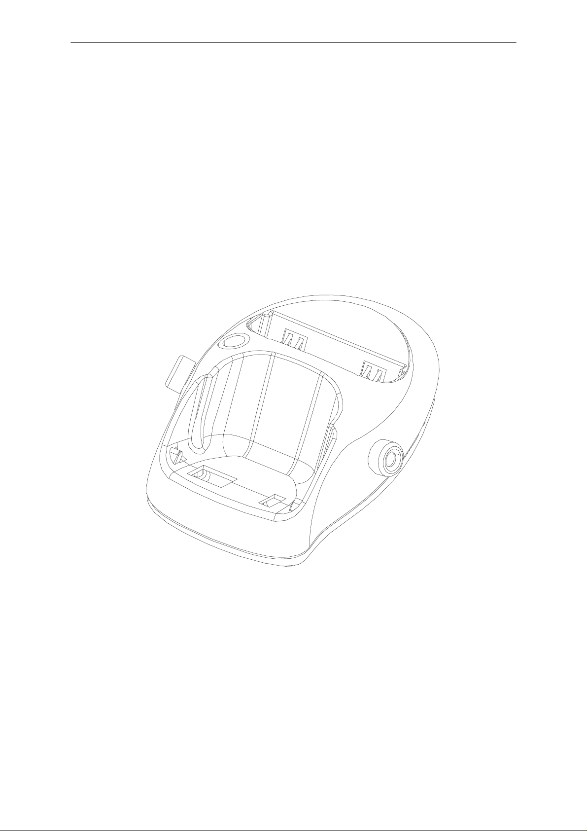
Battery Adapter BDC-3
The Battery Adapter BDC-3 is used along with an external battery
capacity meter to check battery capacity.
Note that Li-ion batteries have an internal protection circuit to prevent
deep discharge.
Product Code
Battery Adapter BDC-3: 0770083
View of BDC-3
Service Tools
Original, 10/98
Page Svt–5
Page 6

NHX-7
PAMS
Service Tools
Service Battery BBD-3
The Service Battery BBD-3 is used in place of the phone’s normal battery
during service, to supply a controlled operating voltage to the phone for
current and charger calibration, and is also required when flashing the
phone.
Note that the cable SCB-3 (0730114) is also required for charger
calibration.
Product Code
Service Battery BBD-3: 0775071
View of BBD-3
Technical Documentation
Page Svt–6
Original, 10/98
Page 7

PAMS
NHX-7
Technical Documentation
Test Frame JSU-7
The Test Frame JSU-7 is used to troubleshoot and repair both system/RF
and UIF modules of NHX–7 phones. *
Test frame includes power connector, RF connector, test rip and possibility
to set UI–module internal/external control by jumpers.
Product Code
Light Module Jig JSU-7: 0770159
View of JSU-7
Service Tools
*) Connect the External antenna cable SCX-7, service Cable SCH-5, and
the DC Cable PCS-1 to the JSU-7 jig.
The service cable SCH-5 can be replaced by the DAU-9P cable.
Note: The nominal supply voltage for JSU-7 is +3.6 V.
The supply voltage must not exceed +5.0 V.
Rip connector layout
Pin Line Symbol Parameter Notes
1 Not connected !
2 Not connected !
3 Not connected !
4 Not connected !
5 Not connected !
Original, 10/98
Page Svt–7
Page 8

NHX-7
PAMS
Service Tools
6 Not connected !
7 ROW0 Keyboard matrix row 0
8 ROW1 Keyboard matrix row 1
9 ROW2 Keyboard matrix row 2
10 ROW3 Keyboard matrix row 3
11 COL0 Keyboard matrix column 0
12 COL1 Keyboard matrix column 1
13 COL2 Keyboard matrix column 2
14 COL3 Keyboard matrix column 3
15 XPWRON Power on/off detection line
16 GND Analog ground
17 KEYBLIGHT Illumination control External control If jumper X7 as-
18 LCDBLIGHT Illumination control External control If jumper X8 as-
19 VBATT_OUT Battery voltage line to current meter
Technical Documentation
NotesParameterLine SymbolPin
sembled to position 1.
sembled to position 1.
If jumper X9 assembled.
20 VBATT_IN Battery voltage line from current meter
21 LCDCLK Display driver clock (external)
22 SCLK Mux’d LCD serial dataclock
23 LCDENX Display driver enable
24 LCDDC Mux’d LCD data or command
25 LCDSDA Mux’d LCD driver serial data
26 LCDRES Reset for display driver
27 VL LCD voltage
28 BUZZER Buzzer PWM control External control If jumper X10 as-
sembled to position 1
29 GND Analog ground
30 GND Analog ground
31 DGND Digital ground
32 DGND Digital ground
33 EARN Speaker negative
34 EARP Speaker positive
35 Not connected !
36 Not connected !
Jumper connections
Jumper X7 sets the control source of the keyboard backlight. When
jumper assembled to position 1, external source is selected. When
position 2 selected, internal (phone) control is selected.
Page Svt–8
Original, 10/98
Page 9

PAMS
NHX-7
Technical Documentation
Jumper X8 sets the control source of the LCD backlight. When jumper
assembled to position 1, external source is selected. When position 2
selected, internal (phone) control is selected.
Jumper X9 sets the current measuring ability on/off. If jumper is
assembled, internal (phone) control without current meter is selected. If
jumper has not been assembled, current measurement option is selected.
The current meter shall be placed between pins 19 and 20. Battery supply
comes from the phone.
Also it is possible to supply battery voltage to directly to UI–module. Then
the supply voltage shall be connected to pin 20. The jumper shall not be
assembled.
Jumper X10 sets the control source of the buzzer PWM signal. When
jumper assembled to position 1, external source is selected. When
position 2 selected, internal (phone) control is selected.
Note: The default setting for jumpers X7,X8 and X10 is position 2 and
jumper X9 is assembled.
Service Tools
View of JSU–7 MS3_01 switching PCB (2/2 rear side)
Position 2.
Position 2.
X7
X8
X9
X10
Position 2.
Original, 10/98
Page Svt–9
Page 10

NHX-7
PAMS
Service Tools
RF cable SCX–7
50 ohm coaxial cable SCX–7, lenght of 0.7 m is used to connect the
antenna connector of the test jig JSU–7 to RF–measuring equipment.
JSU–7 is a service jig for NHX–7 ETACS handportable phone.
Product Code
RF cable SCX–7: 0770161
View of SCX-7
Technical Documentation
Page Svt–10
Original, 10/98
Page 11

PAMS
NHX-7
Technical Documentation
Service Cable SCH-5
The Service Cable SCH-5 is used between the phone and modular
T-adapter.
Product Code
Service Cable SCH-5: 0730098
View of SCH-5
Service Tools
Audio Cable ADS-1
Audio cable is an adapter routing AF signals (MIC/EAR) from 8 pin
modular connector to two BNC connectors. It is used to connect SCH-5
and DAU-9S.
Product code
Audio Cable ADS-1: 0730011
View of ADS-1
Original, 10/98
Page Svt–11
Page 12

NHX-7
PAMS
Service Tools
DC Cable SCB-3
The DC Cable SCB-3 is used to connect the Service Battery to the
charger connection Vin of the phone when doing the charger calibration
service procedure.
Product Code
DC Cable SCB-3: 0730114
View of SCB-3
Technical Documentation
Power Cable PCS-1
The Power Cable PCS-1 is used to connect the module jig JSU–7 to
external power supply.
Product Code
Power Cable PCS-1: 0730012
View of PCS-1
Page Svt–12
Original, 10/98
Page 13

PAMS
NHX-7
Technical Documentation
Antenna Adapter AAT–7X
The Antenna Cable is used to connect the transceiver to measuring
equipment during tuning.
Product Code
Antenna Adapter AAT-7X: 0770162
View of AAT-7X
Service Tools
Original, 10/98
Page Svt–13
Page 14

NHX-7
PAMS
Service Tools
MBUS Cable DAU-9S
The MBUS Cable DAU-9S has a modular connector, and is used with the
modular T-adapter.
Product Code
MBUS Cable DAU-9S: 0730108
View of DAU-9S
Technical Documentation
MBUS Cable DAU-9P
The MBUS Cable DAU-9P has a phone system connector, and is used
between the phone and external devices.
Product Code
MBUS Cable DAU-9P: 0730109
View of DAU-9P
Page Svt–14
Original, 10/98
Page 15

PAMS
NHX-7
Technical Documentation
Modular Cable XCM–1
The modular Cable XCM–1 is a standard 1m long 8–core flat cable with
male modular–8 connectors in both ends.
Product Code
Modular Cable XCM–1 4626131
View of XCM-1
Service Tools
Original, 10/98
Page Svt–15
Page 16

NHX-7
PAMS
Service Tools
Modular T-adapter
The modular T-adapter is a suitable branching unit to provide the needed
parallel modular connections.
Product Code
Modular T-adapter: 4626134
View of Modular T-adapter
Technical Documentation
SW Security Device PKD-1
SW security device is a piece of hardware enabling the use of the service
software when connected to the parallel (LPT) port of the PC. Whitout the
dongle present it is not possible to use the service software. Printer or any
such device can be connected to the PC through the dongle if needed.
Caution: Make sure thet you have switched off the PC and the printer
before making connections!
Caution: Do not connected the PKD-1 to the serial port. You may
damage your PKD-1!
Product Code
SW Security Device PKD-1: 0750018
View of SW Security Device
View of DAU-9P
Page Svt–16
Original, 10/98
 Loading...