

Page 1

After Sales Technical Documentation
NHN–3N Series Transceivers
Chapter 1
General Information
Original 42/96
Page 2

NHN–3N
After Sales
General Information
Technical Documentation
CONTENTS
Introduction 2 – 3. . . . . . . . . . . . . . . . . . . . . . . . . . . . . . . . . . . . . . . . . . . . . . . . . . . . . .
Product Selection 2 – 3. . . . . . . . . . . . . . . . . . . . . . . . . . . . . . . . . . . . . . . . . . . . .
Handportable 2 – 3. . . . . . . . . . . . . . . . . . . . . . . . . . . . . . . . . . . . . . . . . . . . . .
Charger Options 2 – 4. . . . . . . . . . . . . . . . . . . . . . . . . . . . . . . . . . . . . . . . . . . . . .
Product and Module List 2 – 4. . . . . . . . . . . . . . . . . . . . . . . . . . . . . . . . . . . . . . .
Technical Specifications 2 – 5. . . . . . . . . . . . . . . . . . . . . . . . . . . . . . . . . . . . . . . . . . .
General Specifications 2 – 5. . . . . . . . . . . . . . . . . . . . . . . . . . . . . . . . . . . . . . . . .
Mechanical Characteristics 2 – 5. . . . . . . . . . . . . . . . . . . . . . . . . . . . . . . . . . . . .
Electrical Specifications 2 – 6. . . . . . . . . . . . . . . . . . . . . . . . . . . . . . . . . . . . . . . .
Transceiver General Features 2 – 6. . . . . . . . . . . . . . . . . . . . . . . . . . . . . . .
Transmitter Branch 2 – 6. . . . . . . . . . . . . . . . . . . . . . . . . . . . . . . . . . . . . . . . .
Page No
Receiver Branch 2 – 7. . . . . . . . . . . . . . . . . . . . . . . . . . . . . . . . . . . . . . . . . . .
Synthesizer TX Band 2 – 7. . . . . . . . . . . . . . . . . . . . . . . . . . . . . . . . . . . . . . .
Synthesizer RX Band 2 – 8. . . . . . . . . . . . . . . . . . . . . . . . . . . . . . . . . . . . . . .
Transceiver Overview 2 – 9. . . . . . . . . . . . . . . . . . . . . . . . . . . . . . . . . . . . . . . . . . . . .
Introduction 2 – 9. . . . . . . . . . . . . . . . . . . . . . . . . . . . . . . . . . . . . . . . . . . . . . . . . . .
Circuit Description 2 – 9. . . . . . . . . . . . . . . . . . . . . . . . . . . . . . . . . . . . . . . . . . . . .
Interconnection Diagram 2 – 9. . . . . . . . . . . . . . . . . . . . . . . . . . . . . . . . . . . . . . .
Block Diagram 2 – 10. . . . . . . . . . . . . . . . . . . . . . . . . . . . . . . . . . . . . . . . . . . . . . . .
Baseband–Block 2 – 11. . . . . . . . . . . . . . . . . . . . . . . . . . . . . . . . . . . . . . . . . . . . . .
PWRU 2 – 11. . . . . . . . . . . . . . . . . . . . . . . . . . . . . . . . . . . . . . . . . . . . . . . . . . . .
CTRLU 2 – 11. . . . . . . . . . . . . . . . . . . . . . . . . . . . . . . . . . . . . . . . . . . . . . . . . . .
UIF 2 – 11. . . . . . . . . . . . . . . . . . . . . . . . . . . . . . . . . . . . . . . . . . . . . . . . . . . . . . .
AUDIO 2 – 11. . . . . . . . . . . . . . . . . . . . . . . . . . . . . . . . . . . . . . . . . . . . . . . . . . . .
RF–Block 2 – 11. . . . . . . . . . . . . . . . . . . . . . . . . . . . . . . . . . . . . . . . . . . . . . . . . . . .
RX 2 – 11. . . . . . . . . . . . . . . . . . . . . . . . . . . . . . . . . . . . . . . . . . . . . . . . . . . . . . .
SYNT 2 – 11. . . . . . . . . . . . . . . . . . . . . . . . . . . . . . . . . . . . . . . . . . . . . . . . . . . . .
TX 2 – 11. . . . . . . . . . . . . . . . . . . . . . . . . . . . . . . . . . . . . . . . . . . . . . . . . . . . . . .
Power Distribution 2 – 12. . . . . . . . . . . . . . . . . . . . . . . . . . . . . . . . . . . . . . . . . . . . .
Page 1 – 2
Original 42/96
Page 3
After Sales
NHN–3N
Technical Documentation
Introduction
This chapter contains a list of products/modules together with their
associated order codes, and details of the performance specifications for
the NHN–3N Series Transceiver. The performance specifications are split
into general, transmitter, and receiver functions.
Product Selection
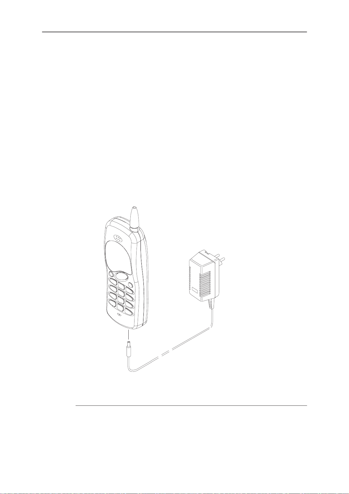
Handportable
The NHN–3N is a handportable cellular phone for the NMT 900 system.
The basic package offers the user a standard battery pack and travel
charger for charging from the mains. The package contains the following
items:
General Information
1.
2.
S0001132
Item/name: Type: Product code:
1. Handportable (see Variant Appendixes)
2. Travel charger (Euro plug) ACH–8E 0675080
Original 42/96
Page 1 – 3
Page 4
NHN–3N
After Sales
General Information
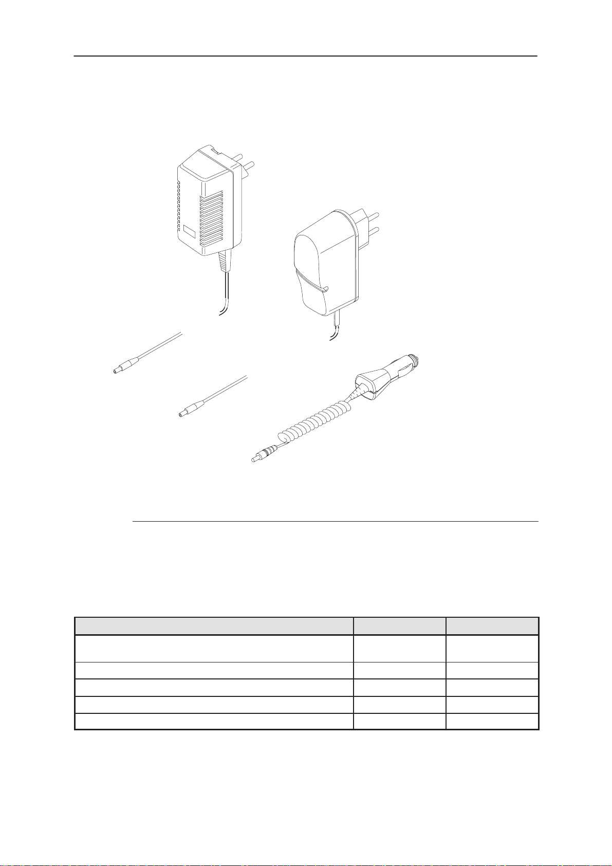
Charger Options
Technical Documentation
1.
2.
3.
Item/name: Type: Product code:
1. Travel charger, trickle (Euro plug) ACH–8E 0675080
2. Travel charger, rapid (Euro plug) ACH–6E 0675087
3. Cigarette lighter rapid charger LCH–6 0675076
Product and Module List
Name of module Type code Material code
Transceiver NHN–3N See variant
Appendixes
System/RF JR8 0200863
Display TE1 0200915
Fixed battery 1200 mAh; NiMH BBF–3 0261299 *)
Mechanics MNHN3NF 0261181
*) Note: Replacement battery pack code: 0080188
Page 1 – 4
Original 42/96
Page 5

After Sales
NHN–3N
Technical Documentation
Technical Specifications
General Specifications
Parameter T emperature °C
Temperature range
Quick charging temperature
Discharge temperature
Mechanical Characteristics
General Information
–25 to +55
+5 to +45
–20 to +65
Unit Dimensions (mm)
(H x W x D)
Transceiver with fixed battery 152X54X32 235 197
Weight (g)
typical
Volume
(cm
3
)
Original 42/96
Page 1 – 5
Page 6

NHN–3N
After Sales
General Information
Technical Documentation
Electrical Specifications
Transceiver General Features
Parameter Notes
Cellular system NMT900
TX frequency band 890.0125 – 914.9875 MHz
RX frequency band 935.0125 – 959.9875 MHz
Duplex spacing 45 MHz
Number of RF channels 1000 (+999 interleaved channels)
Channel spacing 25 / 12.5 kHz
Maximum output power 0.55W
Method of frequency synthesis Dual direct PLL
Power Supply Voltage 4.5...6.8 V
Transmitter Branch
Frequency band 890.0125 – 914.9875 MHz
Output RF power 0.1 or 0,55 W
Spurious signals (TX ON)
Spurious signals (STANDBY)
Modulation method FM
Deviation 4.7 kHz max
Deviation with supervisory signal 5.0 kHz max
FFSK deviation 1200 Hz (”1”)
1800 Hz (”0”)
Harmonic distortion < 5 %
Audio Frequency response 300–500 Hz
500–2000 Hz
2–3 KHz
pre–emphasis
< 0.25 mW, f = 100kHz – 1GHz
< 1 mW, f = 1GHz – 4GHz
< 2 nW, f = 100kHz – 1GHz
< 20 nW, f = 1GHz – 4GHz
2800 Hz dev. +/– 400 Hz
4200 Hz dev. +/– 600 Hz
+1–3 dB
+/– 1 dB
+1–3 dB
6 dB/Oct
Adjacent Channel Power < –37 dBm
Audio Inter–modulation products < –20 dB
Residual Modulation linear
psophometric
Audio Muting > 40 dB
< –20 dB (peak)
< –40 dB (rms)
Page 1 – 6
Original 42/96
Page 7

After Sales
ratio
ratio
NHN–3N
Technical Documentation
Compander SW enabled compression
dynamic range
Output RF power 0,55 W
Number of power levels 2
2:1
0 – –50 dB +/– 1 dB
General Information
Receiver Branch
Frequency band 935.0125 – 959.9875 MHz
Sensitivity –113 dBm (20 dB SINAD psoph. )
Adjacent Channel Selectivity > 67 dB
Spurious Response Rejection > 67 dB
Inter–modulate Rejection > 67 dB
Blocking > 87 dB
Spurious signals (TX OFF)
< 2 nW, f = 100kHz – 1GHz
< 20 nW, f = 1GHz – 4GHz
Audio Inter–modulation Products < –20 dB (1600 Hz)
AM suppression > 30 dB
Hum and Noise linear
phopsometric
Audio Frequency response 300–500 Hz
500–2000 Hz
2–3 KHz
de–emphasis
Harmonic distortion <5 %
Audio Muting > 50 dB
Expander SW enabled compression
dynamic range
RSSI dynamic range 60 dB
Frequency stability +/– 5 ppm
< –20 dB
< –40 dB
+1–3 dB
+/– 1 dB
+1–3 dB
6 dB/Oct
1:2
0 – –50 dB +/– 1 dB
Synthesizer TX Band
Transmitted frequency difference from BS in
conversation mode
Frequency range 890.0125 – 914.9875 MHz
Output level 1dBm +/– 3 dB
+/– 250 Hz
Original 42/96
Page 1 – 7
Page 8

NHN–3N
After Sales
General Information
Phase Noise < –1 16 dBc/Hz (@25KHz)
Residual deviation < 50 Hz
Spurious emissions < –74 dBc
Settling Time CHN–>CHN+? < 35 ms
Technical Documentation
Synthesizer RX Band
Frequency Tolerance at Startup +/– 2.5 ppm
Frequency range 935.0125 – 959.9875 MHz
Output level 1 dBm +/– 3 dB
Phase Noise < –118 dBc/Hz (@25KHz)
Residual deviation < 50 Hz
Spurious emissions < –80 dBc
Settling Time CHN–>CHN+? < 35 ms
Page 1 – 8
Original 42/96
Page 9

After Sales
NHN–3N
Technical Documentation
Transceiver Overview
Introduction
The NHN–3N is a small and light handportable Cellular phone for the
NMT900 system..
The transceiver consist of four modules: JR8 RF/system module, fixed battery, display and mechanics.
The transceiver has a fixed antenna.
The user communicates with the phone via LCD–display, keyboard, and
some audible tones.
Circuit Description
The transceiver electronics consist of Transceiver module PCB. The display
is connected to the transceiver module with a flexible connector . The system
and RF submodules are interconnected with PCB wiring. The unit can be
connected to charger with a charger connector.
General Information
The RF block is designed for a hand portable phone, which operates in
NMT900 systems. The purpose of the RF module is to receive and demodulate the radio frequency signal from the base station, and to transmit a modulated RF signal to the base station. RF parts are designed for 0.55W output
power.
Interconnection Diagram
DISPLAY
2
BATTERY
BBF–3
MIC
63
RADIO MODULE
JR8
BUZZER
22
Original 42/96
229
CHARGKEYPAD
EAR
Page 1 – 9
Page 10

NHN–3N
R
After Sales
General Information
Block Diagram
The NHN–3N consist of a single pcb JR8. JR8 consist of 2 submodules,
BASEBAND and RF. BASEBAND consists of four functional blocks: PWRU
(MUUMI), CTRLU (MCU), UIF, AUDIO (NIPA) and DISPLAY . RF consists of
3 functional blocks: RX, SYNT, TX.
DISPLAY
RESET
SIS
RESET
EEPROM
Technical Documentation
XMIC
VBAT
MUUMI
RESET
M2BUS
XPWROFF
KEYPAD
XEA
MIC EARBUZZER
CLK
MCUNIPA
RESET
DAF
RX
AFC
CLK
MOD
3.6864MHz XPWRON
TXC
RF CONTROL
TX
SYNTE
Page 1 – 10
DUPLEXER
RF BLOCK BASEBAND BLOCK
Original 42/96
Page 11

After Sales
NHN–3N
Technical Documentation
Baseband–Block
PWRU
The power block provides the supply voltages for the phone, and also includes the charging electronics.
CTRLU
Main Features of the CTRLU block:
– system control
– communication control
– authentication
– power up/down control
– battery monitoring
– production testing
– RF–controls
– UIF–interface
– M2BUS interface.
General Information
UIF
Main features of the UIF block:
– Keyboard lighting circuits
– Keyboard switch matrix
– Interface to display module
AUDIO
The block includes all necessary audio functions.
RF–Block
RX
The RX module receives and demodulates the radio frequency signal from
the base station.
SYNT
The transmitter synthesizer generates a frequency modulated RF signal for
the transmitter section. The transmission frequency is generated by a
phase–locked loop (PLL). he synthesizer circuit contains VCO, synthesizer
logic, and loop filter.
The receiver synthesizer operates in the same way as the corresponding circuit in the TX synthesizer . The modulation line is of course missing. The first
injection frequency is supplied to the receiver module.
TX
The Transmitter module generates and amplifies the RF signal to be transmitted to the base station.
Original 42/96
Page 1 – 11
Page 12

NHN–3N
After Sales
VCS
General Information
Power Distribution
VBAT
VREF
VL
VL2
VL3
VA
RECEIVER
VCCR
VSYN
Technical Documentation
SYNTHESIZER
TRANSMITTER
VRF
PWRU
CTRLU
AUDIO
UIF
VBAT
LCD
DISPLAY
Page 1 – 12
Original 42/96
Page 13

After Sales
NHN–3N
Technical Documentation
General Information
[This page intentionally left blank]
Original 42/96
Page 1 – 13
 Loading...