

Page 1
PAMS Technical Documentation
Appendix 1
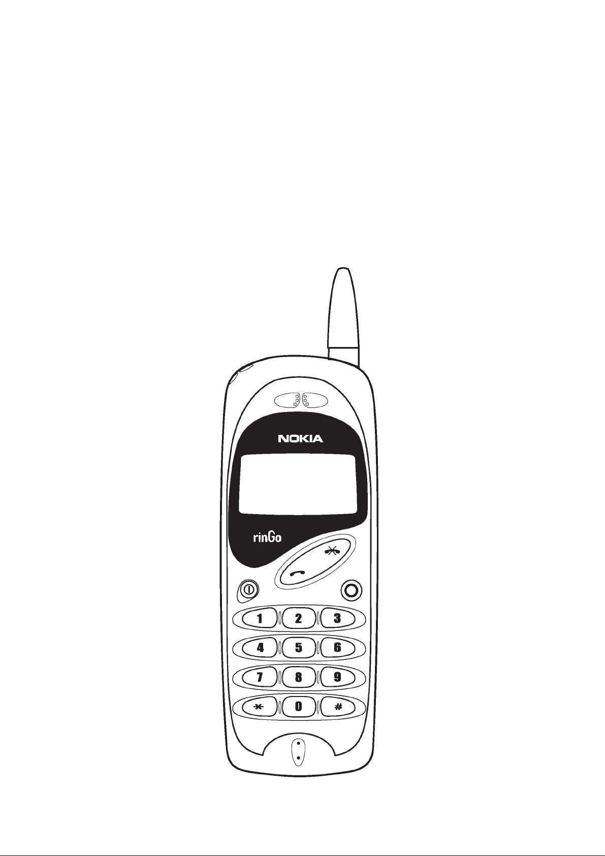
TRANSCEIVER NHN–6NF
Original 11/97
Page 2

NHN–6NF
PAMS
Appendix 1
Technical Documentation
CONTENTS
Appendix 1 1 – 3. . . . . . . . . . . . . . . . . . . . . . . . . . . . . . . . . . . . . . . . . . . . . . . . . . . . . .
Foreword 1 – 3. . . . . . . . . . . . . . . . . . . . . . . . . . . . . . . . . . . . . . . . . . . .
Transceiver NHN–6NF 1 – 3. . . . . . . . . . . . . . . . . . . . . . . . . . . . . . . .
Functional Description 1 – 3. . . . . . . . . . . . . . . . . . . . . . . . . . . . . .
Modules 1 – 4. . . . . . . . . . . . . . . . . . . . . . . . . . . . . . . . . . . . . . . . . .
Exploded View of Transceiver NHN–6NF 1 – 5. . . . . . . . . . . . . .
Assembly Parts of NHN–6NF 1 – 6. . . . . . . . . . . . . . . . . . . . . . .
Quick Guide 1 – 7. . . . . . . . . . . . . . . . . . . . . . . . . . . . . . . . . . . . . . . . .
General 1 – 7. . . . . . . . . . . . . . . . . . . . . . . . . . . . . . . . . . . . . . . . . . .
Memory 1 – 7. . . . . . . . . . . . . . . . . . . . . . . . . . . . . . . . . . . . . . . . . . .
Page 1 – 2
Original 11/97
Page 3

PAMS
NHN–6NF
Technical Documentation
Appendix 1
Foreword
This section of the service manual (Appendix) contains specific details for
the NHN–6NF handportable telephone used on the NMT900 network.
The appendix comprises three chapters as follows: Chapter 1, Foreword
(this chapter); Chapter 2, Transceiver NHN–6NF, containing an exploded
view of the NHN–6NF variant (including a list of assembly parts) plus
component parts lists covering the system module and the display
module; and Chapter 3, Quick Guide, which aims to provide all user
information that service personnel are likely to require during servicing
and repair of equipment.
NOTE: The Service Manual is intended for use by qualified
service personnel only.
Appendix 1
Transceiver NHN–6NF
Functional Description
The transceiver electronics consist of UI module PCB and RF/system PCB.
UI module is connected to system module with a connector. System and rf
submodules are interconnected with PCB wiring. Unit can be connected to
accessories with a bottom system connector, which includes charging and
accessory control.
RF block is designed for a hand portable phone, which operates in NMT900
systems. Purpose of the RF module is to receive and demodulate radio frequency signal from the base station and to transmit a modulated RF signal
to the base station.
Original 11/97
Page 1 – 3
Page 4

NHN–6NF
PAMS
Appendix 1
Modules
Technical Documentation
Unit/type: Product code: Module code:
Transceiver NHN–6NF (orange) 0501643
Transceiver NHN–6NF (ink blue) 0501644
Transceiver NHN–6NF (blue grey) 0501654
• system module JR9B 0201178
• display module TE1 0200915
• mechanics MNHN6N (orange) 0261674
• mechanics MNHN6N (ink blue) 0261676
• mechanics MNHN6N (blue grey) 0261692
**) Note: When ordering the fixed battery as a spare part,
use code 0080188
Page 1 – 4
Original 11/97
Page 5

PAMS
NHN–6NF
Technical Documentation
Exploded View of Transceiver NHN–6NF
Appendix 1
Original 11/97
Page 1 – 5
Page 6

NHN–6NF
PAMS
Appendix 1
Technical Documentation
Assembly Parts of NHN–6NF
ITEM Q’TY CODE DESCRIPTION VALUE, TYPE
1 1 9457641 Window DMC00460
2 1 9456069 Front Cover (orange) DMC01005
1 9456070 Front Cover (ink blue)
1 9457878 Front Cover (blue gray)
3 1 0660130 Antenna Helical 890–960 Mhz
4 1 9790224 Keymat DMC00459
5 1 5140051 Microphone
6 1 9480078 Buzzer gasket
7 1 9467011 Light Guide DMC00579
8 1 5140580 Speaker
M1 1 0201035 JR9 RF/System Module
9 1 9480327 Support Tape DMD02590
10 1 9537039 Chassis/Gasket DMC01023
11 5 6190001 Screw M2x3,8 Pan T6 DMD02124
12 1 0261299 Fixed Battery pack BBF–3
13 2 9480325 Pad Tape DMD02586
14 1 9450902 Back Cover DMD01242
15 3 6150007 Screw M2x8 PH FZN
16 1 9480365 Adhesive tape
17 1 9450876 Screw Cover DMS00210
1 9510342 Antenna Clip DMD01315
Page 1 – 6
Original 11/97
Page 7

PAMS
NHN–6NF
Technical Documentation
Quick Guide
General
– Make a call Area code, phone number, SND
– End a call END
– Answer a call SND
– Clear the display Press and hold END
– Last number redial 0, #
– Lock/unlock keypad * * * *
– Call prevention On/Off *, *, CODE (4 digits)
Appendix 1
or: press SND when the display is empty
Calls can only be made using the Ringo
button, or to the emergency number.
Memory
– Volume control Use SND button:
Volume control has three levels.
Starting volume is level 3. At first
button press, volume is set to level 2,
second button press will select level 1,
third press will return to level 3, etc.
– Emergency services Emergency number, SND
– Store a number *, 1, *, area code, number, #, *
stores to memory location 1
– Fast store Area code, number, *, press and hold 1
stores to memory location 1
– Recall a number 1, #
recalls memory location 1
– One–Touch dialling Press and hold number key (1–9)
calls number in memory location 1–9
– Ringo dialling Press and hold the Ringo button
– Erase a number #, 1, #, *
Original 11/97
calls number in memory location 10
erases memory location 1
Page 1 – 7
Page 8

NHN–6NF
PAMS
Appendix 1
Technical Documentation
This page intentionally left blank.
Page 1 – 8
Original 11/97
 Loading...