

Page 1

PAMS Technical Documentation
NHX–4N
SERVICE SOFTWARE
INSTRUCTIONS
Copyright 1998 Nokia Mobile Phones. All rights reserved.Original 01/98
Page 2

NHX–4
PAMS
Service Software Instructions
AMENDMENT RECORD SHEET
Amendment
Number
Date Inserted By Comments
Technical Documentation
Page 2
Original 01/98
Page 3

PAMS
NHX–4
Technical Documentation
SERVICE SOFTWARE INSTRUCTIONS
Contents
Page no.
Introduction Page 6. . . . . . . . . . . . . . . . . . . . . . . . . . . . . . . . . . . . . . . . . . . .
General Page 6. . . . . . . . . . . . . . . . . . . . . . . . . . . . . . . . . . . . . . . . . . . . .
Minimum Required Servicing Equipment Page 6. . . . . . . . . . . . . . . . .
Mechanical Connections Page 7. . . . . . . . . . . . . . . . . . . . . . . . . . . . . .
Start Up Procedure Page 8. . . . . . . . . . . . . . . . . . . . . . . . . . . . . . . . . . .
Introduction to Service Software Package User Interface Page 8. . . . .
Service Software/Hardware Enviroment Page 8. . . . . . . . . . . . . . . . .
Service Software Enviroment Page 9. . . . . . . . . . . . . . . . . . . . . . . . . .
Service Software Executables Page 9. . . . . . . . . . . . . . . . . . . . . . .
Command Line Parameters Page 9. . . . . . . . . . . . . . . . . . . . . . . . .
Common Properties of the User Interface Page 10. . . . . . . . . . . . . . . . . .
Login Dialog Page 10. . . . . . . . . . . . . . . . . . . . . . . . . . . . . . . . . . . . . . . . .
Main Window Page 11. . . . . . . . . . . . . . . . . . . . . . . . . . . . . . . . . . . . . . . .
Menu Bar Page 13. . . . . . . . . . . . . . . . . . . . . . . . . . . . . . . . . . . . . . . . . . . .
Product Page 14. . . . . . . . . . . . . . . . . . . . . . . . . . . . . . . . . . . . . . . . . . .
Configure Page 14. . . . . . . . . . . . . . . . . . . . . . . . . . . . . . . . . . . . . . . . .
Tuning Page 14. . . . . . . . . . . . . . . . . . . . . . . . . . . . . . . . . . . . . . . . . . . .
Testing Page 15. . . . . . . . . . . . . . . . . . . . . . . . . . . . . . . . . . . . . . . . . . . .
Dealer Page 15. . . . . . . . . . . . . . . . . . . . . . . . . . . . . . . . . . . . . . . . . . . .
View Page 15. . . . . . . . . . . . . . . . . . . . . . . . . . . . . . . . . . . . . . . . . . . . . .
Help Page 15. . . . . . . . . . . . . . . . . . . . . . . . . . . . . . . . . . . . . . . . . . . . . .
Mouse Cursors Page 16. . . . . . . . . . . . . . . . . . . . . . . . . . . . . . . . . . . . . . .
Reserved Keys Page 16. . . . . . . . . . . . . . . . . . . . . . . . . . . . . . . . . . . . . . .
Short Cut Function Keys Page 16. . . . . . . . . . . . . . . . . . . . . . . . . . . .
Alt Hot Keys Page 16. . . . . . . . . . . . . . . . . . . . . . . . . . . . . . . . . . . . . . .
Ctrl Hot Keys Page 17. . . . . . . . . . . . . . . . . . . . . . . . . . . . . . . . . . . . . .
Shift Hot Keys Page 17. . . . . . . . . . . . . . . . . . . . . . . . . . . . . . . . . . . . .
Key Strokes Page 17. . . . . . . . . . . . . . . . . . . . . . . . . . . . . . . . . . . . . . .
Help Functions Page 19. . . . . . . . . . . . . . . . . . . . . . . . . . . . . . . . . . . . . . .
Dialog boxes Page 19. . . . . . . . . . . . . . . . . . . . . . . . . . . . . . . . . . . . . . . . .
Common Dialog boxes Page 19. . . . . . . . . . . . . . . . . . . . . . . . . . . . . .
Note Message Box Page 19. . . . . . . . . . . . . . . . . . . . . . . . . . . . . . .
Query Message Box Page 20. . . . . . . . . . . . . . . . . . . . . . . . . . . . .
Error Message Box Page 20. . . . . . . . . . . . . . . . . . . . . . . . . . . . . .
Custom Dialog boxes Page 21. . . . . . . . . . . . . . . . . . . . . . . . . . . . . . .
Buttons Page 21. . . . . . . . . . . . . . . . . . . . . . . . . . . . . . . . . . . . . . . . . . . . .
Reporting Status Page 22. . . . . . . . . . . . . . . . . . . . . . . . . . . . . . . . . . . . .
Service Software Instructions
NHX–4 Specific Features Page 23. . . . . . . . . . . . . . . . . . . . . . . . . . . . . . . .
Original 01/98
Page 3
Page 4

NHX–4
PAMS
Service Software Instructions
Product Menu Page 23. . . . . . . . . . . . . . . . . . . . . . . . . . . . . . . . . . . . . . . .
New command Page 23. . . . . . . . . . . . . . . . . . . . . . . . . . . . . . . . . . . . .
Open... command Page 23. . . . . . . . . . . . . . . . . . . . . . . . . . . . . . . . . .
Close command Page 23. . . . . . . . . . . . . . . . . . . . . . . . . . . . . . . . . . .
Initialize command Page 24. . . . . . . . . . . . . . . . . . . . . . . . . . . . . . . . .
Faultlog Page 24. . . . . . . . . . . . . . . . . . . . . . . . . . . . . . . . . . . . . . . . . . .
Exit command Page 24. . . . . . . . . . . . . . . . . . . . . . . . . . . . . . . . . . . . .
Configure Menu Page 25. . . . . . . . . . . . . . . . . . . . . . . . . . . . . . . . . . . . . .
Options... command Page 25. . . . . . . . . . . . . . . . . . . . . . . . . . . . . . . .
Directories... command Page 25. . . . . . . . . . . . . . . . . . . . . . . . . . . . .
Faultlog... command Page 26. . . . . . . . . . . . . . . . . . . . . . . . . . . . . . . .
RF Controls Page 26. . . . . . . . . . . . . . . . . . . . . . . . . . . . . . . . . . . . . . .
Tuning Menu Page 27. . . . . . . . . . . . . . . . . . . . . . . . . . . . . . . . . . . . . . . . .
Battery Reference Page 27. . . . . . . . . . . . . . . . . . . . . . . . . . . . . . . . . .
Charger Voltage Adjustment Page 28. . . . . . . . . . . . . . . . . . . . . . . . .
TX Power Tuning Page 29. . . . . . . . . . . . . . . . . . . . . . . . . . . . . . . . . . .
Deviation Tuning Page 30. . . . . . . . . . . . . . . . . . . . . . . . . . . . . . . . . . .
RSSI Reference Adjustment Page 31. . . . . . . . . . . . . . . . . . . . . . . . .
Tuning Values Page 32. . . . . . . . . . . . . . . . . . . . . . . . . . . . . . . . . . . . .
VCTCXO Tuning Page 33. . . . . . . . . . . . . . . . . . . . . . . . . . . . . . . . . . .
Testing Menu Page 34. . . . . . . . . . . . . . . . . . . . . . . . . . . . . . . . . . . . . . . .
Quick Testing Page 34. . . . . . . . . . . . . . . . . . . . . . . . . . . . . . . . . . . . . .
ADC Readings Page 36. . . . . . . . . . . . . . . . . . . . . . . . . . . . . . . . . . . . .
Display Tests Page 37. . . . . . . . . . . . . . . . . . . . . . . . . . . . . . . . . . . . . .
SINAD Page 38. . . . . . . . . . . . . . . . . . . . . . . . . . . . . . . . . . . . . . . . . . . .
Dealer Menu Page 40. . . . . . . . . . . . . . . . . . . . . . . . . . . . . . . . . . . . . . . . .
Subscriber (NAM) Data Page 40. . . . . . . . . . . . . . . . . . . . . . . . . . . . .
NAM Programming Page 43. . . . . . . . . . . . . . . . . . . . . . . . . . . . . . .
Short Code Memory Page 43. . . . . . . . . . . . . . . . . . . . . . . . . . . . . . . .
Set Default Values Page 45. . . . . . . . . . . . . . . . . . . . . . . . . . . . . . . . . .
User Settings Page 45. . . . . . . . . . . . . . . . . . . . . . . . . . . . . . . . . . . . . .
Warranty Information Page 46. . . . . . . . . . . . . . . . . . . . . . . . . . . . . . .
NAM Programming from the keypad Page 48. . . . . . . . . . . . . . . . . .
Activating the NAM Programming Mode Page 48. . . . . . . . . . . .
Programming the NAM Page 48. . . . . . . . . . . . . . . . . . . . . . . . . . .
Location 2 ; Own Number and Name (NAM1) Page 48. . . . . . . .
Location 1; Common Parameters Page 50. . . . . . . . . . . . . . . . . .
Location 6; Purchasing Date Page 51. . . . . . . . . . . . . . . . . . . . . .
Default Parameters Page 51. . . . . . . . . . . . . . . . . . . . . . . . . . . . . .
Table of NAM Programming Commands Page 52. . . . . . . . . . . .
Battery type Page 54. . . . . . . . . . . . . . . . . . . . . . . . . . . . . . . . . . . . . . . . . .
View Page 55. . . . . . . . . . . . . . . . . . . . . . . . . . . . . . . . . . . . . . . . . . . . . . . .
Phone Identity Page 55. . . . . . . . . . . . . . . . . . . . . . . . . . . . . . . . . . . . .
Help Menu Page 55. . . . . . . . . . . . . . . . . . . . . . . . . . . . . . . . . . . . . . . . . . .
Technical Documentation
Page 4
Original 01/98
Page 5

PAMS
NHX–4
Technical Documentation
About WinTesla Page 55. . . . . . . . . . . . . . . . . . . . . . . . . . . . . . . . . . . .
Tuning Instructions for NHX–4 Page 56. . . . . . . . . . . . . . . . . . . . . . . . . . . .
Required Equipment Page 56. . . . . . . . . . . . . . . . . . . . . . . . . . . . . . . . . .
Equipment Setup Page 57. . . . . . . . . . . . . . . . . . . . . . . . . . . . . . . . . . . . .
Equipment Setup For Tuning A Phone Without Removing Covers . . . . . . .
Equipment Setup For Tuning A Phone With Covers Removed . . . . . . . . . . .
Tuning Steps Page 60. . . . . . . . . . . . . . . . . . . . . . . . . . . . . . . . . . . . . . . . .
Battery Reference Page 60. . . . . . . . . . . . . . . . . . . . . . . . . . . . . . . . . .
Reference Charge Voltage Page 60. . . . . . . . . . . . . . . . . . . . . . . . . .
TX Power Level Tuning Page 60. . . . . . . . . . . . . . . . . . . . . . . . . . . . .
Deviation Tuning Page 61. . . . . . . . . . . . . . . . . . . . . . . . . . . . . . . . . . .
RSSI Reference Value Page 62. . . . . . . . . . . . . . . . . . . . . . . . . . . . . .
Tuning Values Page 62. . . . . . . . . . . . . . . . . . . . . . . . . . . . . . . . . . . . .
VCTCXO Page 62. . . . . . . . . . . . . . . . . . . . . . . . . . . . . . . . . . . . . . . . . . . . . .
Appendix 1, Vocabulary Page 63. . . . . . . . . . . . . . . . . . . . . . . . . . . . . . . . . .
Service Software Instructions
Page 58
Page 59
Original 01/98
Page 5
Page 6

NHX–4
PAMS
Service Software Instructions
Introduction
General
The NHX–4 Service Software is specially designed to facilitate the servicing of
sixth generation cellular telephones.
The software can be used to control the phone according to the user’s requirements merely by entering commands via the keyboard / mouse of a PC connected
to the phone.
The software features include also tuning of the phone.
This section refers to TACS Service Software Version 1.00. NMP After Sales will
notify service personnel about future upgrades via Technical Bulletins. Software
upgrades will be available from your local NMP outlet.
Minimum Required Servicing Equipment
Technical Documentation
– Computer: Intel 386/33 MHz or compatible with one unused serial port
(COM1 or COM2*), one parallel port (LPT1), hard disk recommended.
– Operating System: DOS Version 5 & Microsoft Windows 3.11 or later
– Display: VGA based display
– Service Software program: for 3.5” disk (product code: 0774077)
– WinTesla Service Software: SWSA1 (product code: 0774077)
for 3.5” disk.
– Software Protection Key PKD–1 (product code 0750018)
– M2BUS interface cable SCN–3
*)
Note: A number of PC’s of an older generation use the Intel, National Semiconductor, or
United Microelectronics IC 8250 as the serial port UART. This is a comparatively
inefficient circuit for current purposes and does not necessarily support the
M2BUS adapter at 9600 baud. The newer UART’s NS16450 and NS16550AF of
National Semiconductor offer solutions for these problems.
Page 6
Original 01/98
Page 7
PAMS
NHX–4
Technical Documentation
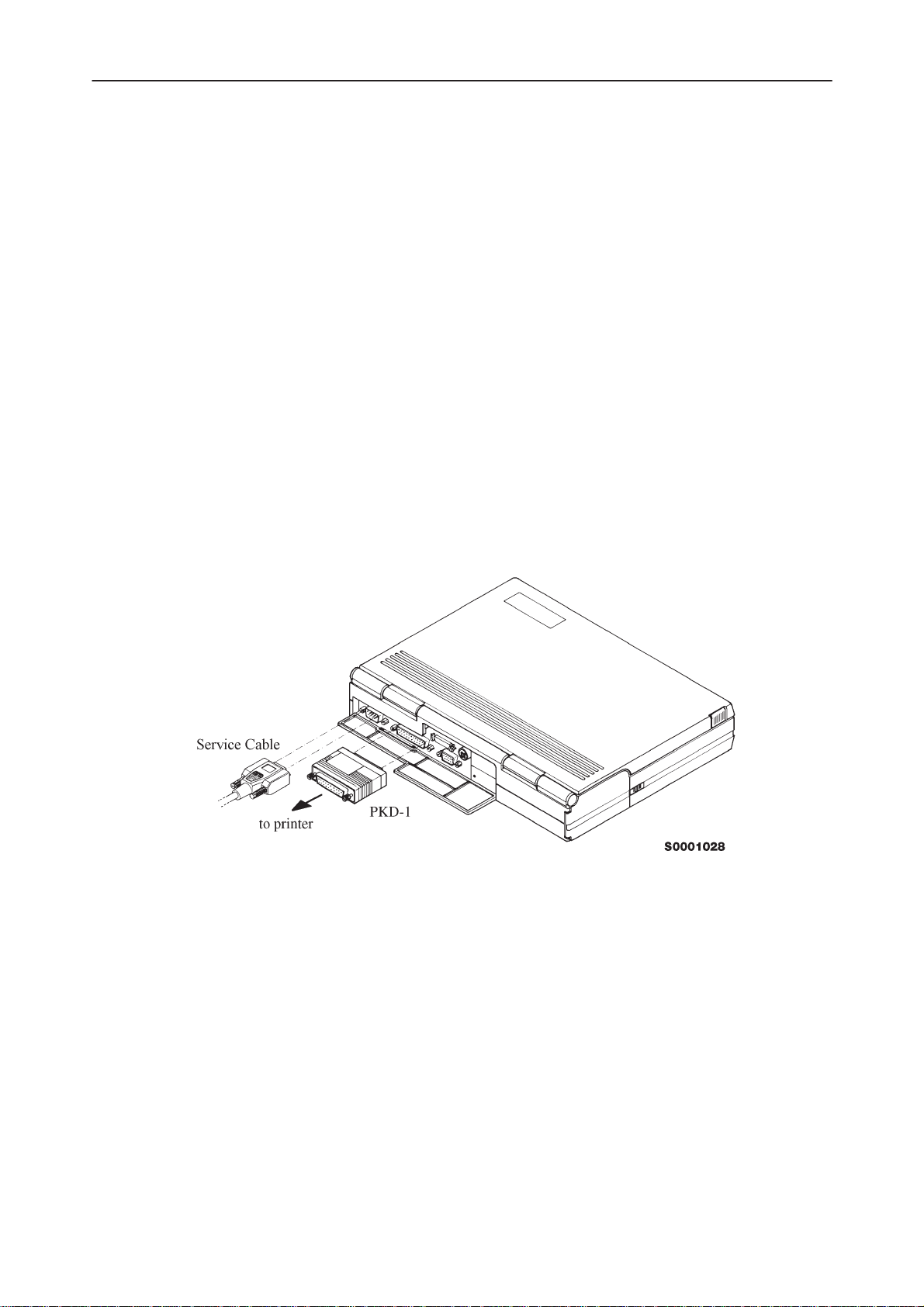
Mechanical Connections
Caution: Ensure that you have switched off the PC and the printer before
making connections !
Caution: Do not connect the PKD–1 to the serial port. This could damage
the PKD–1 !
The software controls the phone via a separate adapter connected to the serial
port of the PC and to the telephone’s M2BUS (SCN–3 and XCM–1).
Attach the protection key PKD–1 to parallel port one (25–pin female D–connector)
of the PC. When connecting the PKD–1 to the parallel port be sure that you insert
the PC end of the PKD–1 to the PC (male side). If you use a printer on parallel
port one, place the PKD–1 between the PC and your printer cable.
The PKD–1 should not effect devices working with it. If some errors occur (errors
in printing are possible) please try printing without the PKD–1. If printing is OK
without the PKD–1 please contact your dealer. We will offer you a new PKD–1 in
exchange for your old one.
Service Software Instructions
Attach one end of the M2BUS service cable, SCN–3, to the PC serial port and the
other end to the bottom connector of the phone.
Original 01/98
Page 7
Page 8
NHX–4
PAMS
Service Software Instructions
Start Up Procedure
Start the phone by pressing the power–on button of the handset. Switch PC power
on.
To installing software, proceed as follows:
1. Insert Service Software disk into
drive A of your PC
2. Start Windows: type
3. Start Installing program: select
4. Follow Installation Software
instructions
WIN
and press
File –> Run
menu, then type
OK
press
button
Technical Documentation
Enter
from Program Manager
A:INSTALL
and
Introduction to Service Software Package User Interface
This chapter gives a short description of the Service Software properties.
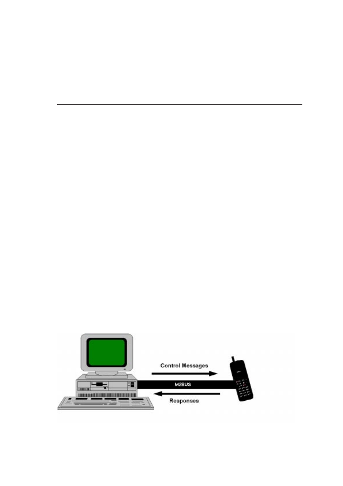
Service Software/Hardware Enviroment
To run the Service Software, a parallel port software protection device (PKD–1)
has to be connected. The user can use the Service Software functions for testing
all supported Phone Types. The functions send messages from the PC to the
phone, receives results and show them on the PC display. The messages are sent
via a low level NMP proprietary bus protocol. An example bus is an M2BUS interface, which needs M2BUS adapter (DAU–2) connected to the PC RS–232 port
and special M2BUS cable.
Page 8
Original 01/98
Page 9

PAMS
NHX–4
Technical Documentation
The recommended minimum hardware standard to run the Service Software
package is any computer which is 386 33Mhz or greater with at least 4 MB of
memory and VGA type display (640x480). This assumes that only the Service
Software package is active, i.e. other Windows packages are not running in the
background.
Note: if the Service Software is to be run on a laptop, the power saving feature
MUST be switched off.
Service Software Enviroment
Service Software user interface is intended for Microsoft Windows 3.11 environment running in enhanced mode. For those who are familiar with Windows environment this application will be easy to use. Detailed information about Windows
and application usage can be found from Ref 3– Microsoft Windows Version 3.11
Users Guide chapter one (Windows Basics) and chapter two (Application Basics).
As an ordinary Windows application, the main idea in the user interface is that
selections are made with menus, push buttons and shortcut keys. Selections can
be done by using keyboard and/or mouse. When messages from phone are received, they cause display updating in special display windows. There is always a
status bar displayed at the bottom of the main window which contains information
about current actions.
Service Software Instructions
Service Software Executables
Only one executable is needed – WinTesla.
For NHX–4, there are two DLL’s:
– Functionality DLL is NHX4.DLL
– User Interface DLL is NHX4EN.DLL
Command Line Parameters
There are NO command line parameters.
Original 01/98
Page 9
Page 10
NHX–4
PAMS
Service Software Instructions
Common Properties of the User Interface
This chapter describes how the User Interface CLF must appear to the user.
The User Interface MUST be capable of being driven without the use of a mouse,
as the service engineer rarely has space on the bench to use a mouse.
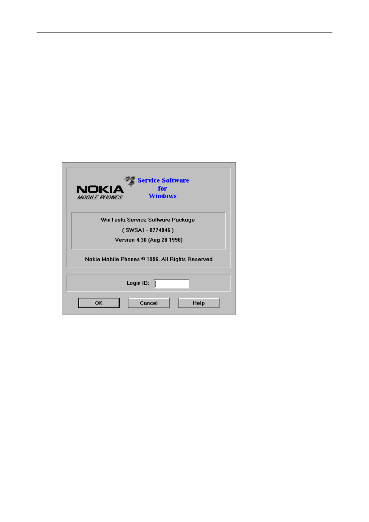
Login Dialog
When the Service Software application is invoked, by checking on the Service Software icon, the Login dialog box will be displayed on the screen.
Technical Documentation
Nokia logo and application name bitmap (–)
Application version static text (–)
Copyright notice static text (–)
Login Box edit box (–)
Page 10
Displays Nokia logo and name of the application.
Contains the name and version of the application.
Copyright is informed as: “Nokia Mobile Phones (c) 1996. All
Rights Reserved”.
The user Login ID edit box, where the user enters his faultlog user
name.
Original 01/98
Page 11
PAMS
NHX–4
Technical Documentation
OK button (default key)
The user name is stored in memory and the dialog box is closed.
When the dialog box is closed, the application starts.
Cancel button (ESC)
The Dialog box is closed and application is started, but the Faultlog
feature is disabled.
Help button (F1)
Activates the Windows Help application and displays context sensitive Help.
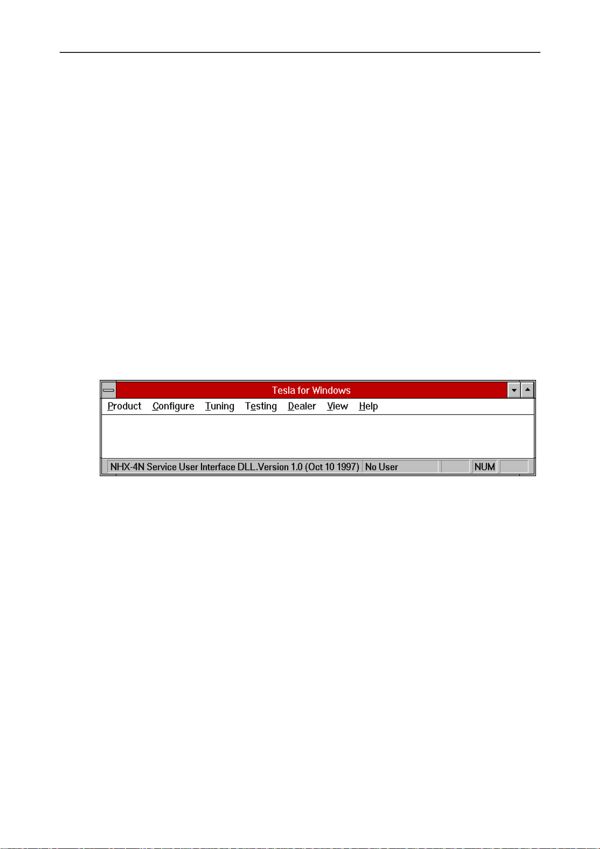
Main Window
The application supports a
vice software interface will present a
ance.
Service Software Instructions
Multiple Document Interface (MDI).
Single Document Interface (SDI)
However, the ser-
appear-
Note: MDI is to allow for future expansion, e.g. R&D features.
Title bar
title bar
The
A title bar contains the following elements:
• Application Control–menu button
• Maximise button
• Minimise button
• Name of the application
• Restore button
is located at the top of the window.
The properties of these elements and their usage is described in Ref 3– Microsoft
Windows Version 3.1 Users Guide chapter one (Windows Basics) and chapter two
(Application Basics).
Original 01/98
Page 11
Page 12

NHX–4
PAMS
Service Software Instructions
Menu bar
menu bar
The
The menu bar is a dynamic element and is dependent on the dongle type fitted,
and whether a phone is connected.
Underlined characters in menu names and options indicates that the menu selection can be done by pressing
lected by activating menu bar with
highlight the desired menu. In that case, selection is done by pressing
Menus can also be selected by using the mouse as described in Ref 3–Microsoft
Windows Version 3.11 Users Guide
Status bar
status bar
The
The status bar contains information about the menu selections and events.
The left area of the status bar describes the actions of menu items as the user
uses the arrow keys to navigate through menus.
is below the title bar and contains all available menu selections.
is displayed at the bottom of the Service Software main window.
Alt+ underlined character
Alt
– key ( or
F10
key ) and using arrow–keys to
Technical Documentation
. Options can also be se-
Enter
.
The status bar texts are explained in detailed in each of command’s description.
The right areas of the status bar indicate which of the following keys are latched
down:
Indicator Description
USER Entered Login ID.
CAP The Caps Lock key is latched down.
NUM The Num Lock key is latched down.
SCRL The Scroll Lock key is latched down.
Tool bar
The
tool bar
document.
is NOT defined and will not be implemented until specified by this
Page 12
Original 01/98
Page 13

PAMS
NHX–4
Technical Documentation
Menu Bar
The Service Software package will have two menu bar configurations. The first, is
an abbreviated version that contains the minimum number of menus that allows
package configurations when a phone is NOT connected. The second is described below:
The menu bar MUST only contain the follow menus for the Service Software package when a phone is connected:
roduct*
• P
onfigure*
• C
• T
uning
sting
• Te
• D
ealer
Service Software Instructions
iew
• V
• H
elp*
* – always displayed, even if no phone is connected.
A menu is broken down into sections that are indicated with menu separators.
Each sections identifies a logical difference from itself and other sections, i.e. between transmitter and receiver. Any items that are required to be added to a menu
lists will be added on the bottom of the appropriate menu section list. If a new item
is to be added which is common to two or more phone types, then that menu item
will become a common menu item.
The menu lists will use the Microsoft [...] symbol after an item name to indicate
that selecting that item will NOT initiate an operation immediately, i.e. a dialog box
will be displayed for the user to select options or type in data and press the OK
button before the operation is performed.
Original 01/98
Page 13
Page 14
NHX–4
PAMS
Service Software Instructions
Product
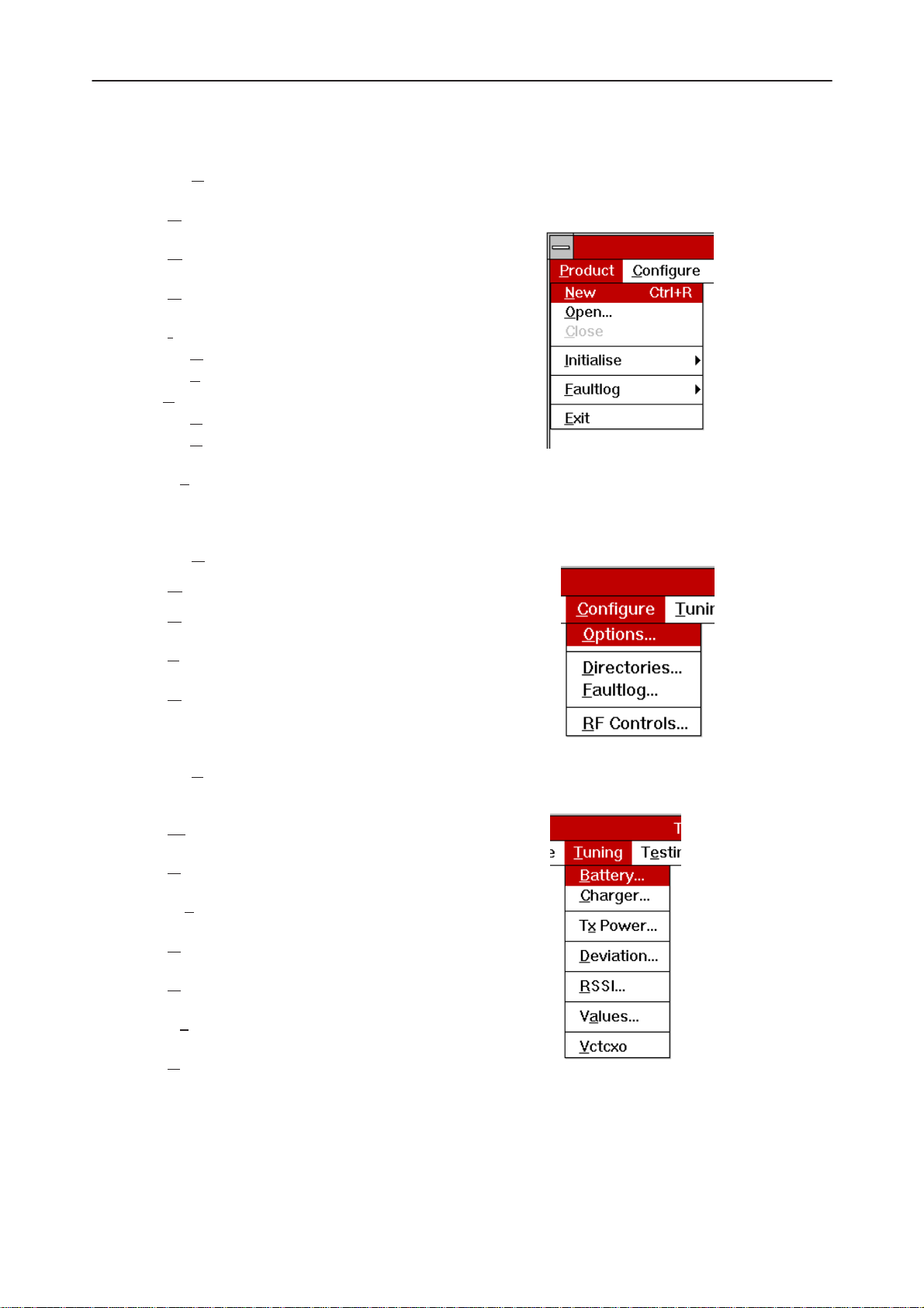
The Product menu contains the following menu items:
• N
ew Ctrl+R
pen...
• O
• C
lose
nitialize
• I
ormal Mode F5
• N
• Local Mode Shift+F5
aultlog
•F
• Activate Faultlog... F9
dit Faultlog...
• E
it Alt+F4
• Ex
Configure
Technical Documentation
Tuning
The Configure menu contains the following menu items:
• O
ptions...
irectories...
• D
aultlog...
• F
• R
F Controls
The Tuning menu contains the following menu menu items:
attery
• B
• C
harger...
Power...
• Tx
• D
eviation...
SSI...
• R
• Va
• V
Additional menu items may be added within the sections according to the phone
type being tuned, e.g. a Charger tuning menu item will be added after the Battery
tuning item, but not in the Transmitter tuning section.
Page 14
lues...
ctcxo
Original 01/98
Page 15
PAMS
NHX–4
Technical Documentation
Testing
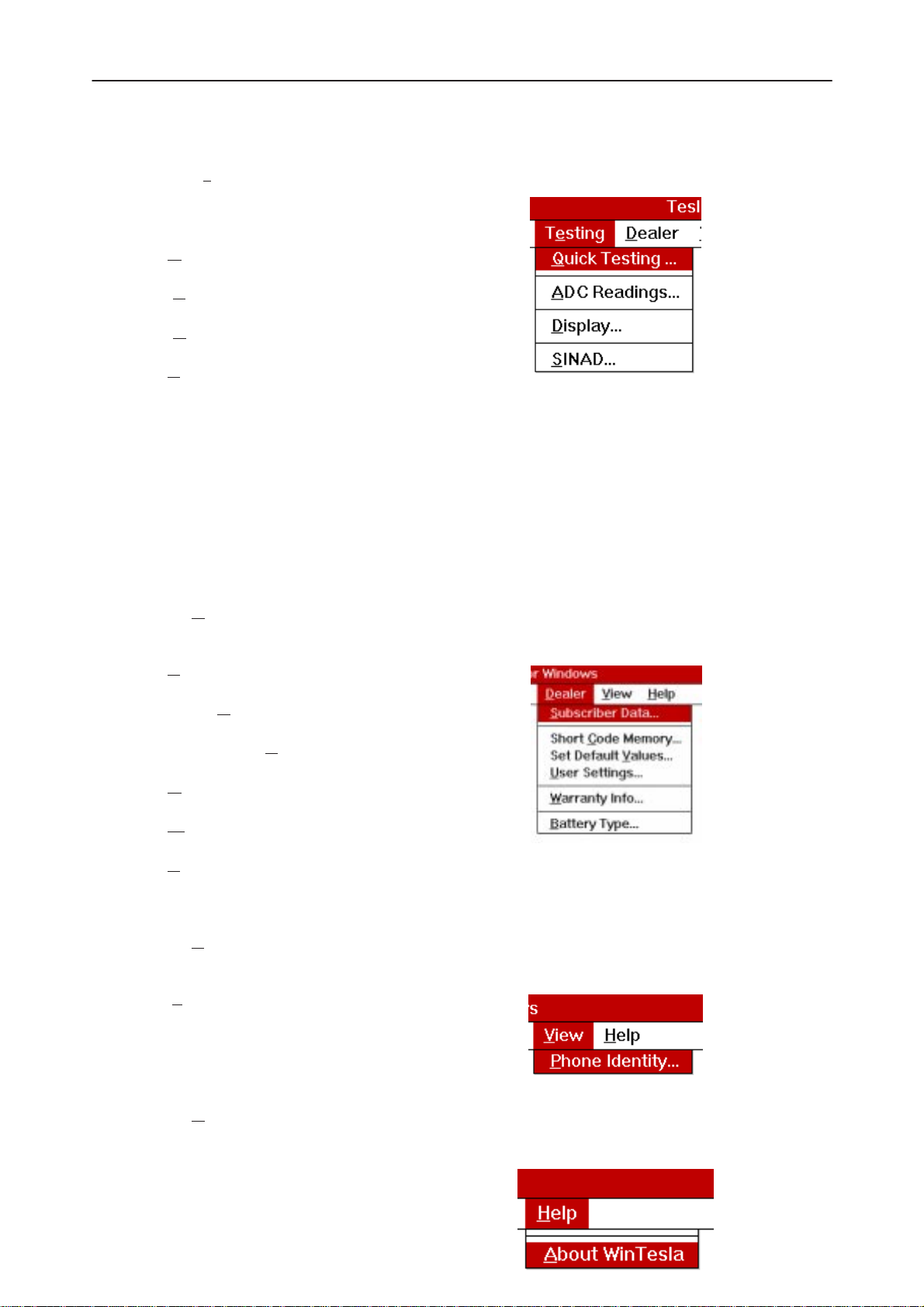
The Testing menu contains the following menu items:
• Q
uick Testing...
DC Readings
• A
• D
isplay
INAD...
• S
Additional menu items may be added within the sections according to the phone
type being tested.
Where a menu item consists of more than one test, a pop–up menu may be added to identify the appropriate sub–tests, e.g. there may be two receiver tests required for a particular phone type (Bit Error Rate and RSSI Monitoring). These will
be shown as a popup from the Receiver menu item.
Service Software Instructions
Dealer
View
The Dealer menu contains the following menu items:
• S
ubscriber Data...
• Short C
• Set Default V
ser Settings...
• U
• W
attery Type...
• B
The View menu contains the following menu item:
• P
hone Identity...
ode Memory...
alues...
arranty Info...
Help
The Help menu contains the following menu items:
Original 01/98
Page 15
Page 16

NHX–4
PAMS
Service Software Instructions
• I
ndex
eneral Help
• G
sing Help
• U
• A
bout WinTesla
Mouse Cursors
The standard Windows pointer will be used as the mouse cursor.
During time consuming tasks e.g. communication to phone, an hour glass will be
shown informing the user that a task is in progress. The application uses the hour
glass cursor to inform user that the application has taken the control and any actions from user will be ignored.
Reserved Keys
The following Hot keys and Short Cut keys are reserved either as Microsoft standard keys or as part of the Common Look and Feel specified by this document.
Technical Documentation
Short Cut Function Keys
Key Description Defined by
F1 Context Sensitive Help Microsoft
F5 Normal Mode NMP
Shift+F5 Local Mode NMP
F9 Activate Faultlog NMP
F10 Goto Menu Bar Microsoft
Ctrl+F4 Close Active Window Microsoft
Alt Hot Keys
Key Description Defined by
Alt+F4 Exit Active Application Microsoft
Alt+H Help Microsoft
Page 16
Original 01/98
Page 17

PAMS
NHX–4
Technical Documentation
Ctrl Hot Keys
Key Description Defined by
Ctrl+N File – New Microsoft
Ctrl+O F
Ctrl+P F
Ctrl+R P
Shift Hot Keys
Key Description Defined by
Shift+F5 Local Mode NMP
Key Strokes
Key Description Defined by
Service Software Instructions
ile – Open Microsoft
ile – Print Microsoft
roduct – New NMP
Alt+P Product Menu NMP
Alt+P,N N
Alt+P,O O
Alt+P,C C
Alt+P,I I
Alt+P,I,N N
Alt+P,I,L L
Alt+P,F F
Alt+P,F,A A
Alt+P,F,E E
Alt+P,E E
Alt+C C
ew NMP
pen NMP
lose NMP
nitialize Pop–up NMP
ormal Mode NMP
ocal Mode NMP
aultlog Pop–up NMP
ctivate Faultlog NMP
dit Faultlog NMP
xit Application NMP
onfigure NMP
Alt+C,O O
Alt+C,D D
Alt+C,F F
Alt+C,R R
Original 01/98
ptions NMP
irectories NMP
aultlog NMP
F Controls NMP
Page 17
Page 18

NHX–4
PAMS
Service Software Instructions
Alt+T T
Alt+T,B B
Alt+T,C C
Alt+T,V V
Alt+T,X Tx
Alt+T,D D
Alt+T,R R
Alt+T,A Va
Alt+E Te
Alt+E+Q Q
Alt+E,A A
Technical Documentation
uning Menu NMP
attery NMP
harger NMP
CTCXO NMP
Power NMP
eviation NMP
SSI NMP
lues NMP
sting Menu NMP
uick Testing NMP
DC Readings NMP
Alt+E,D D
Alt+E,S S
Alt+E,E E
Alt+D D
Alt+D,C Short C
Alt+D,U U
Alt+D,V Set Default V
Alt+D,W W
Alt+V V
Alt+V,P P
Alt+H H
Alt+H,I I
isplay NMP
INAD NMP
rror Codes NMP
ealer Menu NMP
ode Memory NMP
ser Menu Settings NMP
arranty Info NMP
iew Menu NMP
hone Identity NMP
elp Menu Microsoft
ndex Microsoft
alues NMP
Alt+H,G G
Alt+H,U U
Alt+H,A A
Page 18
eneral Help Microsoft
sing Help Microsoft
bout WinTesla Microsoft
Original 01/98
Page 19

PAMS
NHX–4
Technical Documentation
Help Functions
The Help User Interface will be the standard Windows help tool called WinHelp.
The context sensitive help is activated with F1–key. Help contains also Using Help
which describes how to use help facility. Refer to the Windows manual for detailed
description on the Windows Help.
Dialog boxes
The Service Software application uses many different dialog boxes. Dialog boxes
are used to display data and prompt the user for input.
Dialog boxes are opened from menus or with shortcut keys. Dialog boxes have
different properties but some features are common.
All service dialog boxes must be modal, that is, the user will not be able to start
another operation without first closing the present dialog box.
All dialog boxes will contain the following entities:
Service Software Instructions
– Help button
– Title bar
– At least one button other than Help
– Application Control–menu Button
Common Dialog boxes
This sections describes the common dialog boxes used in the Service Software
package, and the context in which they will be used.
Note Message Box
When the user has made an illegal selection, a
opened and message text is displayed. The message box is also opened when
the program has some information for the user. The size of the dialog
box may vary. An information dialog box is recognized by the !–icon.
The dialog box will also contain an OK button and a Help button.
OK button (default key):
note message box
dialog will be
Help button (Alt+H):
Original 01/98
Acknowledge displayed information and continue. The dialog box is
closed after selection.
Opens context sensitive help as F1–key does.
Page 19
Page 20

NHX–4
PAMS
Service Software Instructions
Query Message Box
Confirmations and questions are asked in
box is recognized by the ?–icon.
The dialog box will also contain a Yes button, a No button, and a Help button.
Yes button (Alt+Y or Y) (default key):
Accepts confirmation or question.
No button (Alt+N or N):
Denies confirmation or question.
Help button (Alt+H):
Opens context sensitive help as F1–key does.
Technical Documentation
a query message box
. A query dialog
The buttons may also be OK and Cancel. The operation of these buttons are the
same as in the Note dialog box.
Error Message Box
Error message dialog boxes use the Stop–icon. When a “Stop”–dialog box is
shown, the current operation is terminated.
The dialog box has a description about the failed operation and reason. Pressing
F1 (Help) application opens the appropriate help topic that gives information about
recommended actions.
The dialog box will also contain an OK button and a Help button.
OK button (default key):
Help button (Alt+H):
Acknowledges displayed information and terminate current operation. The dialog box is closed after selection.
Page 20
Open context sensitive help as F1–key does.
Original 01/98
Page 21

PAMS
NHX–4
Technical Documentation
Custom Dialog boxes
All custom dialog boxes will contain the predefined buttons as defined below in the
section –
button types, but the addition of these non–standard buttons should be carefully
considered to minimise any inconsistencies between implementations.
The buttons will be positioned down the right–hand side of the dialog boxes. The
default action will be OK, except where that default action could result in an irretrievable failure.
All tuning dialogs that contain tuning results, will display the old tuned data read
from the phone before the tuning was performed, as well as the newly tuned data.
List boxes will be used to display lists of data, such as tuning data, test results
etc.
The use of Radio buttons should be limited and carefully considered. The use of
radio buttons defines the number of possible choices available to the user, which
may be acceptable for one project, but not for another.
Buttons.
Service Software Instructions
However, it is recognised that features may require additional
Buttons
All buttons must be the Microsoft style of buttons.
In general, the default button will be the OK button, the Close button or the Yes
button, but this will depend on the context of the dialog box that the button is
associated with.
OK button:
Close button:
Accepts and validates entered settings and values and closes the
dialog. If the values have not been changed, then no action will be
taken. The status bar will reflect the status. The user should only be
queried, if the settings or values accepted will over–write data that
CAN NOT be reproduced.
A greyed OK button indicates that settings selected by the user are
not acceptable.
Closes the current dialog box. Does not send or store anything and
closes the dialog. The Close button is only used for dialogs that do
not set or change any data.
Original 01/98
Page 21
Page 22

NHX–4
PAMS
Service Software Instructions
Cancel button (Esc):
Cancel operation. Does not send or store anything and closes the
dialog box.
A greyed Cancel button indicates that it is not possible to quit from
this dialog box.
Yes button (ALT+Y or Y):
Replies Yes to a question asked of the user.
No button (ALT+N or N):
Replies No to a question asked of the user.
Help button (ALT+H):
Opens context sensitive help as F1–key does.
Technical Documentation
Reporting Status
The status bar will be used to report the present status to the user. When a feature is initiated, the status bar will be updated with a brief description of the function. The status bar will also be updated at key points in a time consuming function.
If an error is to be reported to the user, it will be displayed in the status bar as well
as displayed in a common error dialog box. This will mean the user is not delayed
from progressing on to the next operation unless an error occurs, in which case,
the user will have to acknowledge the error by pressing the OK button.
Page 22
Original 01/98
Page 23

PAMS
NHX–4
Technical Documentation
NHX–4 Specific Features
Product Menu
New command
Activation Status Bar Text
Alt, P, N Rescan a new phone
Ctrl+R
This command scans a new product. When phone is found a product specific
functionality module is loaded. If no phone or wrong phone/cellular type is detected, functionality is unloaded and user is informed.
This function is also started automatically when the application is started. The
user can also specify a regular poll which enables the WinTesla application to
scan the new phone periodically. If the phone is still the same, no changes are
done. If the phone is changed (with same phone type only the serial number is
changed), the phone will be initialized to a normal mode. If the phone is changed
to a different phone type, the current dlls are unloaded and new ones are loaded
for that phone.
Service Software Instructions
The initialization routine checks the phone’s cellular type (GSM/PCN), and if an
unsupported phone is detected, the WinTesla application does not load the dlls.
If quick info view is open, the window will be automatically updated.
If phone identification view is open, the window will be automatically updated.
Open... command
Activation Status Bar Text
Alt, P, O Force load phone specific functionality
Enables the user to force load specific phone’s WinTesla dll’s.
Close command
Activation Status Bar Text
Alt, P, C Close loaded functionality
Closes loaded functionality and sends reset to phone if dlls are loaded by Open
command.
Original 01/98
Page 23
Page 24

NHX–4
PAMS
Service Software Instructions
Initialize command
Activation Status Bar Text
Alt, P, I –
Opens a submenu which contains the following options:
Faultlog
Activation Status Bar Text
Alt, P, F –
Opens a submenu which contains following options:
Activate Faultlog...
Activation Status Bar Text
Technical Documentation
Alt, P, F, A Activates faultlogging
F9
E
dit Faultlog...
Activation Status Bar Text
Alt, P, F, E Activates faultlog editing
Exit command
Activation Status Bar Text
Alt, P, X Exit application
Alt + F4
Double click the application’s Control menu button:
This command ends the Service Software session.
Page 24
Original 01/98
Page 25

PAMS
NHX–4
Technical Documentation
Configure Menu
Options... command
Activation Status Bar Text
Alt, C, O Edit Service Software options The Options dialog box contains the following items:
Language drop down list. Current password edit box: New Password edit box: Retype Password edit box: User ID edit box.
Service Software Instructions
M2BUS Com Port drop down list. Automatic Rescan edit box. Note! This documentation will be updated as soon as WinTesla integration
is ready.
Directories... command
Activation Status Bar Text
Alt, C, D Edit directory settings The Directories dialog box contains the following items:
ID Data edit box:
ogs edit box:
L Fault log file(s) edit box: Data Validation file(s) edit box: Flash i
low failures edit box:
B
Note! This documentation will be updated as soon as WinTesla integration
is ready.
Original 01/98
mages edit box:
Page 25
Page 26

NHX–4
PAMS
Service Software Instructions
Faultlog... command
Activation Status Bar Text
Alt, C, F Edit faultlog settings The Faultlog dialog box contains the following items:
Fault log enabled/disabled radio buttons: Allow M
utomatic fault log prompting enabled 1/Disabled 2 radio buttons:
A
S
tation identity edit box:
Country of R
W
arranty period months edit box / drop down list:
Maximum T
anual Entry enabled/disabled radio buttons:
epair edit box:
ime to repair edit box:
Technical Documentation
RF Controls
Activation Status Bar Text
Alt, C, R Edit RF Controls
The RF Controls dialog box contains the following items:
TX Level edit box RSSI Channel edit box Mid Channel edit box High Channel edit box Cancel button (Esc): Write File button (Alt+F):
Page 26
Original 01/98
Page 27

PAMS
NHX–4
Technical Documentation
Tuning Menu
The tuning menu offers functions for ME adjustments.
Battery Reference
Activation Status Bar Text
Alt, T, B Tune Battery Reference Voltage
Service Software Instructions
The Battery Reference dialog box contains the following items:
R
epeat button (Alt+R):
Save & Next button (Alt+N):
ave & Exit button (Alt+S):
S
Cancel button (Esc):
Original 01/98
Read AD Converter Value (average of 10 readings).
Tuning values are saved to the phone, and the next tuning dialog is
entered.
The dialog box is closed, and the tuning values are saved to the
phone.
The dialog box is closed, and the tuning values are not saved to the
phone.
Page 27
Page 28

NHX–4
PAMS
Service Software Instructions
Charger Voltage Adjustment
Activation Status Bar Text
Alt, T, C Tune Reference Charge Voltage
Technical Documentation
The Charger Voltage Adjustment dialog box contains the following items:
R
epeat button (Alt+R):
Read AD Converter Value (average of 10 readings).
Save & Next button (Alt+N):
Tuning values are saved to the phone, and the next tuning dialog is
entered.
ave & Exit button (Alt+S):
S
The dialog box is closed, and the tuning values
phone.
Cancel button (Esc):
The dialog box is closed, and the tuning values
phone.
are saved
to the
are not saved
to the
Page 28
Original 01/98
Page 29

PAMS
NHX–4
Technical Documentation
TX Power Tuning
Activation Status Bar Text
Alt, T, X Tune TX power
This command is used to tune the phone’s TX power levels. The transmitter will
be switched on at power level 7 on middle channel (default: channel 1988).
Service Software Instructions
The TX Power Tuning dialog box contains the following items: Fine buttons (Alt++/–):
Increase/decrease DAC value by 1.
Coarse buttons (Alt+PgDn/PgUp):
Increase/decrease DAC value by 10.
Save & N
ave & Exit button (Alt+S):
S
Cancel button (Esc):
ext button (Alt+N):
Tuning values are saved to the phone, and the next tuning dialog is
entered.
The dialog box is closed, and the tuning values
phone.
The dialog box is closed, and the tuning values
phone.
are saved
are not saved
to the
to the
Original 01/98
Page 29
Page 30

NHX–4
PAMS
Service Software Instructions
Deviation Tuning
Activation Status Bar Text
Alt, T, D Deviation Tuning
A number of deviation tunings are grouped together in this command. They are,
however, still tuned independently of each other.
Technical Documentation
The Deviation Tuning dialog box contains the following items: Fine buttons (Alt++/–):
Increase/decrease tuning factor by 1. Nominal values Increase/decrease by 2.
Ne
xt buttons (Alt+E):
Cursor jumps next deviation values, between Sig Tone, Maximum
and Nominal.
Save & N
S
ave & Exit button (Alt+S):
Cancel button (Esc):
ext button (Alt+N):
Tuning values are saved to the phone, and the next tuning dialog is
entered.
The dialog box is closed, and the tuning values
The dialog box is closed, and the tuning values
phone.
are saved
are not saved
to the phone.
to the
Page 30
Original 01/98
Page 31

PAMS
NHX–4
Technical Documentation
RSSI Reference Adjustment
Activation Status Bar Text
Alt, T, R Tune RSSI reference value
This consists of tuning the reference value for the RSSI meter. It is carried
out without an external signal using noise.
Service Software Instructions
The RSSI reference Adjustment dialog box contains the following items:
epeat button (Alt+R):
R
Read AD converter value (average of 10 readings).
Save & N
S
ave & Exit button (Alt+S):
Cancel button (Esc):
ext button (Alt+N):
Button is not used, always disabled.
The dialog box is closed, and the tuning values
phone.
The dialog box is closed, and the tuning values
phone.
are saved
to the
are not saved
to the
Original 01/98
Page 31
Page 32

NHX–4
PAMS
Service Software Instructions
Tuning Values
Activation Status Bar Text
Alt, T, A Activate Tuning Values and Tuning Default command
With this command you can save the read Tuning Data from the EEPROM, and
save factory default tuning values to phone. You can read/save those values from/
to file as well.
Technical Documentation
The Tuning Values dialog box contains the following items: Cancel button (Esc):
The dialog box is closed.
D
efault button (Alt+D):
The dialog box is closed, and the default tuning values are saved to
the phone.
rite Phone button (Alt+W):
W
The dialog box is closed, and the tuning values from the selected file
are saved to the phone.
ead Phone button (Alt+R):
R
Tuning values are read from the phone.
Save File button (Alt+S):
Tuning values are saved as a file, the name of which is requested.
Page 32
Original 01/98
Page 33

PAMS
NHX–4
Technical Documentation
VCTCXO Tuning
Activation Status Bar Text
Alt, T, V Tune VCTCXO
This command is used to tune the VCTCXO frequency of the phone.
Service Software Instructions
The VCTCXO Tuning dialog box contains the following items:
O
K button (Alt+O):
The dialog box is closed, and tuning
Cancel button (Esc):
Dialog is closed and tuning
elp button (Alt+H):
H
Not implemented.
Undo button (Alt+U):
Returns original values to the VCTCXO number services line.
VCT
CXO Default button (Alt+U):
Writes VCTCXO default values values to the VCTCXO number services line.
is saved
is not saved
to phone.
to phone.
Original 01/98
Page 33
Page 34

NHX–4
PAMS
Service Software Instructions
Testing Menu
The Testing Menu allows the Service Technician to switch a phone to Local mode
in order to attempt to simulate a reported fault or configure a phone to test a certain parameter. It allows the technician complete control over internal and external
audio, and the RF settings.
When Testing is selected, the phone is placed into Service mode automatically.
This is known as Local mode. Unless the user changes this configuration, using
File, the phone receiver is tuned to Channel 1988; the Transmitter synthesizer is
also tuned to Channel 1988 but with the PA switched off.
Quick Testing
Activation Status Bar Text
Alt, E, Q Open the Quick Testing dialog box
This command opens a Window allowing the user full control over the channel the
phone is tuned to; the transmit power state; and access to some simple audio
routing and signal switching.
Technical Documentation
The Quick Testing dialog box contains the following items:
R
T
Page 34
x Path button (Alt+R):
Select Rx path (Mute/Ear/XEar)
x Path button (Alt+T):
Select Tx path (Mute/Mic/XMic)
Original 01/98
Page 35

PAMS
NHX–4
Technical Documentation
olume button (Alt+V):
V
Select volume level (1–5)
Loop button:
Audio loop On/Off.
Tx Synthesizer button (Alt+Y):
Tx synthesizer On/Off.
Tx Power Le
Compander button (Alt+O):
Sig
nal Tone button (Alt+G):
vel button (Alt+E):
Tx power level (Off, 0–7)
Compander On/Off.
Signalling tone On/Off.
Service Software Instructions
Supervisory Tone button (Alt+P):
Supervisory tone (Off, 5970 Hz, 6000 Hz, 6030 Hz)
W
ide Band Data button (Alt+W):
Wide Band Data On/Off.
Buzzer button (Alt+B):
Buzzer On/Off.
Channel edit box (Alt+C):
The user can enter here the channel number that is used for both
transmission and receiving. The frequency of the selected channel is
shown after selection.
Close button (Alt+Esc):
Close dialog box.
H
igh Channel button (Alt+H):
Select High channel (600)
Mi
d Channel button (Alt+I):
Low Channel button (Alt+L):
Original 01/98
Select Middle channel (1988)
Select Low channel (1329)
Page 35
Page 36

NHX–4
PAMS
Service Software Instructions
Channel Up button (Alt++):
Increase channel number by 1.
Channel Dn button (Alt+–):
Decrease channel number by 1.
ADC Readings
Activation Status Bar Text
Alt, E, A Open the ADC Readings dialog box
This displays a table showing the following readings of the A/D converters.
Technical Documentation
Item: Name: Function:
0 VBATSW Battery voltage
1 CHRGMON Charge voltage
2 BSI Battery size indication
3 BTEMP Battery temperature
4 RSSI Received Signal Strength
5 TXI Transmit power monitor
7 XMIC External microphone line state
The A
Close button (Alt+Esc):
Help button (Alt+H):
DC Readings dialog box contains the following items:
The dialog box is closed.
Not implemented.
Page 36
Original 01/98
Page 37

PAMS
NHX–4
Technical Documentation
Display Tests
Activation Status Bar Text
Alt, E, D Open the Display Tests dialog box
This enables checking of the operation of the display segments.
The Display Tests dialog box contains the following items: Close button (Alt+Esc):
The dialog box is closed.
Service Software Instructions
Help button (Alt+H):
Not implemented.
Original 01/98
Page 37
Page 38

NHX–4
PAMS
Service Software Instructions
SINAD
Activation Status Bar Text
Alt, E, S Open the RX SINAD and XEAR level dialog box
This command is used to test SINAD and XEAR level.
Technical Documentation
The RX SINAD and XEAR level dialog box contains the following items:
OK–Done button (Enter):
Cancel button (Alt+Esc):
Page 38
Enter XEAR measurement.
The dialog box is closed.
Original 01/98
Page 39

PAMS
NHX–4
Technical Documentation
Service Software Instructions
OK–Done button (Enter):
The dialog box is closed.
Cancel button (Alt+Esc):
The dialog box is closed.
Help button (Alt+H):
Not implemented.
Original 01/98
Page 39
Page 40

NHX–4
PAMS
Service Software Instructions
Dealer Menu
Selecting Dealer will bring up a sub–menu as shown below:
– Subscriber Data
– Short Code Memory
– Set Default Values
– User Settings
– Warranty information
– Battery type
Subscriber (NAM) Data
Activation Status Bar Text
Alt, D, S Open the Subscriber Data dialog box This can be used to program all the Subscriber Data and Common NAM Data in-
formation into a telephone. This can also be programmed through the phone’s
keypad.
Technical Documentation
Note: If you wish to only view and not change the NAM information,
press Esc to exit the screen.
Any NAM in the phone can be read from/written to by selecting 1. When a selection is made, all the NAM information displayed on the PC is updated. Basic information displayed next to 1/2 is operator name (if the phone has been programmed using the customization feature), and Subscriber Number (MIN–P).
Page 40
Original 01/98
Page 41

PAMS
NHX–4
Technical Documentation
From this example it can be seen that NAM 1 has been programmed. The ESN of
the phone is also clearly displayed.
Dealers are strongly advised to use the customisation feature. For any operator
they could store, as a default, the following parameters:
Number (MIN–P)
– This option allows the entry of the subscriber’s number, the network code and
the country code.
Wake up
– At this point you can define for example the phone owner’s name to appear
in the wake up display. In case no entry is made, the subcriber’s number will
be show in the wakeup display.
Emergency
– Emergency phone numbers, one or more emergency numbers can be de-
fined, each number should be separated with the #–mark. The maximum
number of emergency numbers depends on the lenght of the numbers. The
total size of the special parameters is limited by the display size (32 characters). these numbers can be called even if the phone is locked. Default numbers are 999#112 for UK and 112#113#115#116#118 for Italy.
Service Software Instructions
Lock Code
– Lock code option enables defining an individual lock code for the user.
Programming Date
– Purchasing date is used for warranty purposes. This location should be pro-
grammed when the phone is delivered to the customer. This location can be
programmed only once, when the contents of the location is 0000. After it is
programmed, it can be read but not changed any more.
Mobile Country & network Code (MCC & MNC)
– MCC; This number is used to define the country code of the phone, for ex-
ample: UK= 234.
– MNC; Enables selection of the system (operator) used; e.g. in the UK, 0
stands for VODAFONE and 2 for CELLNET.
Home Area (AID)
– This number entered defines the home traffic area of the phone. The num-
ber contains information on the country code (bits 14–11), the system bit (bit
10) and the traffic area (bits 9–0).
Original 01/98
Page 41
Page 42

NHX–4
PAMS
Service Software Instructions
Initial Paging Channel (IPCH)
– This number is used to define the first channel to be searched in the home
traffic area. For example in tke UK, 323 means CELLNET and 23 VODAFONE.
Access Overload Class (ACCOLC)
– This number is used to identify which overload class the phone belongs to.
Numbers 0–9 corresponds to normal phone class (typically 0 + last digit of
MIN).
SCM
– Station Class Mark: 2 digits. In TACS this is always 19 and cannot be
changed by the PC.
First & Last DCCA and First & Last DCCB
– At this command you can define DCC channels for certain TACS systems
(not needed in UK).
Technical Documentation
Access Method
– This is used to determine whether the phone must respond to local control
messages sent from exchange.
ROAM Enable
– This is used to enable/disable ROAM function.
Country Check
– This option enables/disables Country check.
China ROAM Indicator
– This is used to enable/disable China ROAM indicator.
Language
– Three languages can be selected (English, Italian or Spanish).
Page 42
Original 01/98
Page 43

PAMS
NHX–4
Technical Documentation
NAM Programming
The process for programming a NAM with this method is as follows:
1. Select NAM 1. (TACS only NAM1)
2. Select Operator – scroll through the available defaults using the arrow keys
until you find the desired default. All the default information will be displayed
on the PC screen
3. Select Number and program the new subscriber number using the normal
text editing keys
4. Select Wake up and program the new Wake up message using the normal
text editing keys. To help with the message alignment, the phone’s display
will constantly be updated during this process
5. Select lock code and program the new lock code using the normal text
editing keys
6. Select
Write Phone
Service Software Instructions
button to save to EEPROM.
Alternatively, the user is able to program each individual parameter if they
choose not to use the customization feature.
Short Code Memory
Activation Status Bar Text
Alt, D, C Short Code Memory
Selecting Dealer/Short Code Memory opens the short code memory dialog box. In
this box, you can view and edit all memory locations of the phone. Memory locations are 50. You can also store the information to a file and read information from
a file. It is also possible to read short code memory files generated by other product’s service software. The following Service Software supports this general file
format.
The Edit SC
M dialog box is shown below:
Original 01/98
Page 43
Page 44

NHX–4
PAMS
Service Software Instructions
Technical Documentation
In the editing dialog box, edit or type in a new name and number. You can change
the field with the
able to accept the new values and return to the full SCM dialog box by pressing
Enter
or by clicking the corresponding button.
The Edit SC
Cancel button (Alt+Esc):
W
rite Phone (ALT+W):
ead Phone (ALT+R):
R
Save File (ALT+S):
Tab
key or clicking with a mouse. When this is complete you are
Esc
will cancel the operation.
M dialog box contains the following items:
The dialog box is closed.
Writes SID data to the phone. Before writing the user is asked to
confirm the writing.
Reads SID data from the phone and updates it to the display
Writes SID data to file. You can select the file to write to from the File
selection dialog box.
L
Page 44
oad File (ALT+L):
Reads SID data from file. You can select a file to be loaded from the
File selection dialog box.
Original 01/98
Page 45

PAMS
NHX–4
Technical Documentation
Set Default Values
Activation Status Bar Text
Alt, D, V Open Set Default Values dialog box.
The Set Default Values dialog box contains the following items:
rite Phone (ALT+W):
W
Service Software Instructions
Cancel button (Alt+Esc):
User Settings
Activation Status Bar Text
Alt, D, U Open User Menu Settings dialog box. By selecting Dealer/User Menu Settings you can view and change the following
User Menu parameters:
Writes default values to the phone, and closes the dialog box..
The dialog box is closed.
Original 01/98
Page 45
Page 46

NHX–4
PAMS
Service Software Instructions
–L
ights
mergency
–E
–K
eypad Tones
ne Touch Dial (Not in NHX–4N)
–O
ock
–L
–R
inging Type
– Ringing V
all Restrictions (Not in NHX–4N)
–C
You can move between these groups by using the
ting using the arrow keys. Alternatively, you can click on the desired value with the
mouse. Press
the new settings to the EEPROM or press
ing the original values.
rite Phone (ALT+W):
W
olume
Enter
or click on the corresponding button with the mouse to save
Technical Documentation
Tab
key and select a new set-
Esc
to exit the dialog box without alter-
Writes user menu settings to the phone, and closes the dialog box.
Cancel button (Alt+Esc):
The dialog box is closed.
Warranty Information
Activation Status Bar Text
Alt, D, W Open Warranty Information dialog box.
NOTE! Command Warranty Information contains also editing repair month
though it is not transferred to other phone.
If phone is not Warranty Defective Phone, command asks if repair month is edited
or warranty information transferred. If phone is warranty defective phone, command automatically activates repair month editing.
Page 46
Original 01/98
Page 47

PAMS
NHX–4
Technical Documentation
The W
Cancel button (Alt+Esc):
T
R
1)
Short Code Memory, User Menu Settings, manufacturing month, purchasing
month and warranty serial number.
Warranty serial number of exchange phone is:
phone is empty.
arranty Information dialog box contains the following items:
The dialog box is closed.
ransfer Warranty Information button (Alt+T):
Transfers warranty information to another phone, and closes the
dialog box.
epair Month To Phone button (Alt+Esc):
Closes the dialog box, and saves the repair date to the phone.
Warranty Information contains contents of NAM (except NAM password),
a)
serial number of original phone if warranty serial number of original
Service Software Instructions
b)
warranty serial number of original phone if warranty serial number of
original phone is NOT empty.
2)
Original phone will be made warranty defective phone when warranty
information is transferred.
3)
Warranty information will not be transferred to other phone if
a)
Original phone is warranty defective phone.
b)
NAM password of original phone differs from that of exchange phone.
c)
Exchange phone is warranty defective phone.
NOTE! In cases b) and c) you must immediately return the original phone
to jig, to avoid making it to warranty defective phone!
Original 01/98
Page 47
Page 48

NHX–4
PAMS
Service Software Instructions
NAM Programming from the keypad
NHX–4N phone is equipped with one NAM. The NAM parameters have to be
programmed by the dealer before the phone can be used. This can be done in
two ways, either by using the keypad or by using a special Service Software. If
you are using the Service Software, refer to the respective user manual for further details.
Activating the NAM Programming Mode
The NAM programming from the keypad is done by using a special NAM programming menu.
The NAM programming mode is turned on by entering special password code
OK
(or
STO
and
*, 6, 0, 3, 1, 2, #, 1, 2, 3, 4, 5, *0 (Long)
This password is supplied to each dealer separately. If the phone is equipped
with the unchurnable software feature, this password has to be preprogrammed
to the dealer (or operator) specific password, otherwise the factory preprogrammed password can be used. Changing the password requires a special
Service software. The password is programmed by the PC to the EEPROM. It
cannot be changed from the keypad.
) key, e.g.
Technical Documentation
If the password entered was correct the NAM programming mode is switched
on.
Programming the NAM
When the NAM programming mode is on, the short code memory is replaced
with six special locations for the NAM parameters
Location: Contents:
1 Special parameters
2 Own number + name for NAM1
3 Parameters for NAM1
4 Not in use
5 Not in use
6 Purchasing date
Location 2 ; Own Number and Name (NAM1)
In the NAM programming mode these locations can be used as any other short
code memory locations. E.g. the number 813 448 4111 for NAM1 would be programmed as:
Page 48
8, 1, 3, 4, 4, 8, 4, 1, 1, 1, *2(Long)
Original 01/98
Page 49

PAMS
NHX–4
Technical Documentation
Note that the own number is entered as a normal phone number, i.e. in TACS
as STD+MSIN (Subscriber Trunk Dialling + Mobile Station Identification Number). The own number will be displayed to the user exactly in the same format
as stored to the memory location in startup.
You can program the NAMs in any order.
The recall function also works as normally, e.g. the above own number pro-
gramming could be checked by recalling the location 2 in the NAM programming mode:
#2 (Long)
The name part of the NAM location 2 can be used to give the name of the network operator, dealer etc. If the name part is programmed, it will be shown on
the display each time the phone is switched on as the so called wake–up message. If the name part is not programmed, own number is used in the message. The name part is available only for the location 2. The name part is given in the ALPHA mode after the own number:
Service Software Instructions
8, 1, 3, 4, 4, 8, 4, 1, 1, 1, ABC, N, A, M, E, ABC, #2,(Long)
The new programmed NAM info is in effect after you have turned the power off
and on again and selected the just programmed NAM from the menu. If the
NAM info is erroneous, the NAM ERROR note will appear and the phone will
not operate. Check that all parameters are given and do not exceed their
range. At least one of the NAMs and the special parameters have to be correct.
The NAM programming mode is cleared by turning the power off. The date of
the NAM programming is not saved.
Normal short code memory operations for other locations (above 6) are not
available during the NAM programming mode.
Location 3 . TACS Parameters (NAM1)
For each NAM, two locations have to be programmed, one for the own number
told above and one for the parameters (3 for NAM1). The contents of the parameter locations are of the form:
MCC+MNC*AID*EX*IPCH*ACCOLC*LC
Where:
*
= separator: press * on keypad.
MCC+MNC
Original 01/98
= Mobile Country + Network Code: 4 digits
(e.g. UK/VODAFONE = 2340, UK/CELLNET = 2342),
range 0 – 9999.
Page 49
Page 50

NHX–4
PAMS
Service Software Instructions
AID
= Area ID (SIDH equivalent), range 0 – 32767
EX
= Access method:
1 = country code used
0 = country code not used
IPCH
= Initial Paging Channel: 3–4 digits (typically
323 for B and 23 for A system), range 0 – 2047.
ACCOLC
last digit of MIN), range 0 – 15.
LC
= Lock Code: 4 digits, range 0 – 9999. Default:1234.
Note that all the parameters are stored to a single location and the upper part
(first 16 digits) is only visible while the
ing of these fields is shown below:
Display: Meaning: Obtained by:
= Access Overload Class: 2 digits (typically 0 +
2340*
SND
MCC+MNC*
Technical Documentation
key is pressed. An example group-
upper part:
press
SND
key
2051*1*2 AID*EX*IPC
3*2*1234 H*ACCOLC*LC
Location 1; Common Parameters
A common NAM location 1 is used to store some special parameters. All these
parameters have a default factory setting and programming of these parameters is not mandatory. The format of these parameters are:
EMER#ALRTSEQ*2DIGITCALL*LAN*CC*RE
Where:
#,*
= separator: use # –key for emergency numbers,
EMER
= Emergency numbers, default 911,*911. One or more
emergency numbers can be defined, The numbera should
be separated by the # character.
EMER1#EMER2#EMER3#EMER4#EMER5
lower part:
normal display
use * –key for others entries.
Page 50
The maximum number of emergency numbers depends
on the length of the numbers. The total size of the special
parameters is limited by the display size (32 characters).
These numbers can be called even if the phone is locked.
Default: 999#112 for UK, 112#113#115#116#118 for Italy
Original 01/98
Page 51

PAMS
NHX–4
Technical Documentation
ALRTSEQ
2DIGITCALL
LAN
CC
= Country check:
= Alert sequence:
= Two digit service call:
= Language, 1 digit:
Service Software Instructions
1 = UK
Default: 1 for UK, 0 for Italy
0 = 2 digit call off
Default: 0 for UK, 1 for Italy
0 = English
1 = Italy
2 = Spanish
0 = no country check, no auto redial
1 = country check, no auto redial
RE
= Roam Enable (1 = enable, 0 = disabled), default: 0.
Location 6; Purchasing Date
Location 6 in NAM programming mode is reserved for the purchasing date.
Purchasing date is used for warranty purposes. This location should be programmed when the phone is delivered to the customer.
The content of the locations is:
MMYY
where:
This location can be programmed only once, when the contents of the location
is 0000. After it is programmed, it can be read but not changed any more.
,
MM
= month
YY
= year (e.g. 0895 is August 1995)
Typically: 1
Default Parameters
Default values are used for the following parameters and they cannot be
changed by the keypad NAM promgramming mode.
Original 01/98
Page 51
Page 52

NHX–4
PAMS
Service Software Instructions
SCM
= Station Class Mark: 2 digits (In TACS default is 19.)
DCC
= Dedicated Control Channel: 4 digits. (TACS only, defaults
are: First DCC A 23, B 323, Last DCC A 43, B 343)
PSM
= (Preferred System Mark) is derived from the AID/SIDH and
cannot be changed.
The factory preprogrammed default values for the NAM locations are:
Location: TACS/UK:0 *60312#12345
1 999#112#1*0*0*1*0
2 1111111111
3 1111*2051*0*23*1*1234
4
5 1111*2051*0*23*1*1234
6 0000
Note that these factory presettings can be modified without notice. Also the
whole short code memory including the last called number location (0) is
cleared by the factory preprogramming.
Technical Documentation
Table of NAM Programming Commands
Own number (NAM1):
Function:
Password, *0(Long) Enter NAM programming mode
number,*
number,
name,
mcc+mnc,*,aid,*,ex, Store parameters for NAM1.
*,ipch,*,accolc,*,lc,
*3(Long)
Checking of the NAM:
2#
ABC
hold
3,#
SND
hold
2(Long)
ABC
, Store both name and number for
ABC,*2(Long)
END
END
Store only own number for NAM1
NAM1.
Function
Check NAM1 number
and name
Clear display
Check NAM1 parameters
Check upper part of NAM1
parameters.
Clear display
Page 52
Original 01/98
Page 53

PAMS
NHX–4
Technical Documentation
4#
END
hold
5#
hold
END
Lock code:
1#
0,8,9,5,*,6(Long)
PWR
PWR
Service Software Instructions
Check NAM2 number
Clear display
Check NAM2 parameters.
Clear display
Function:
Check special parameters
Set purchasing date to August 1995
Exit NAM programming mode by
switching power off.
Switch power on, check operation of
NAMs programmed:
Original 01/98
Page 53
Page 54

NHX–4
PAMS
Service Software Instructions
Battery type
Activation Status Bar Text
Alt, D, B Open Battery Type dialog box.
By selecting Dealer/Battery Type you can view and change the battery type to 800
or 1250 mAh.
Technical Documentation
The Battery Type dialog box contains the following items: Close button (Alt+Esc):
The dialog box is closed.
R
ead Phone button (Alt+R):
Reads battery type from phone.
Write Phone button (Alt+W):
Closes the dialog box, and saves the battery type to the phone.
Help button (Alt+H):
Not implemented.
Page 54
Original 01/98
Page 55

PAMS
NHX–4
Technical Documentation
View
Phone Identity
Activation Status Bar Text
Alt, V, P Open Phone Identity Information dialog box.
By selecting this option you can see phone type and version.
Service Software Instructions
The Phone Identity Information dialog box contains the following items:
Close button :
Help Menu
Choose Help/Using Help to obtain information on how to use the help facilities.
About WinTesla
Activation Status Bar Text
Alt, H, A Shows the WinTesla software version, user interface,
M2BUS support, and NHX–4N supporting DLL versions.
The dialog box is closed.
Original 01/98
Page 55
Page 56

NHX–4
PAMS
Service Software Instructions
Tuning Instructions for NHX–4
In contrast to earlier second–generation analog cellular phones tuning operations of the NHX–4 are carried out using the Service Software software. The
Service Software program turns the phone into the Locals mode, in which the
phone can be outwardly controlled via the M2BUS interface.
Tuning is based on the Service Software software communicating with the D/A
and A/D converters of the phone.
The calibration data of the phone resides on the EEPROM. The contents of the
EEPROM can be read by the Service Software software. The program also enables writing of the factory preset calibration data to the EEPROM, after which
the whole tuning process should be carried out.
If a repair has been carried out on the RF section of a system module then
the appropriate tunings should be performed as described in the following section and using the on–screen help menus as a guide. Spare system modules
will be delivered pre–tuned from the factory and will not require re–tuning.
Technical Documentation
N.B. During tuning, proceed as follows:
– Take care not to damage sensitive measuring instruments with excessive
RF power.
– Carry out all tuning steps in the shortest possible time to avoid excessive
heating of RF units.
– Perform all tuning steps in the order presented.
– Never try to mask a fault by tuning it out!
Required Equipment
– PC/AT computer with Service Software software; see Sect. Service Software
intructions on installation and use.
– M2BUS adapter DAU–2 and other service accessories; see equipment set-
up pictures.
– Audio analyzer
– RF power meter, power measurement sensitivity –10 dBm.
– RF generator
– Device to provide specified testmodulation to modulate RF generator.
Page 56
– Multimeter or DVM.
– Attenuator and branching unit.
– Power supply, nom. voltage 4.8 V.
Original 01/98
Page 57

PAMS
NHX–4
Technical Documentation
Equipment Setup
Turn off the computer before connecting to avoid possible damage to the serial
port.
Connect the M2BUS adapter SCN–3 ( item 1) to the phone. Connect 9–pin
male D–connector in your PC serial port.
Then connect SCN–3 audio lines to the measurement station by using the audio cables.
For transmit and audio measuring and adjustment connect SCN–3 EAR/MIC
breakout cables as follows:
– EAR line to test equipment (Marconi 2960) AF INPUT
– MIC line to test equipment (Marconi 2955) AF GEN OUTPUT
Connect SCN–3 power connectors to the supply voltage. Power supply must
be set to 5.0 V, when the phone is tuned.
Note: The supply voltage must be set to 4.8 V, when battery and charger refer-
ences are tuned.
Service Software Instructions
Original 01/98
Page 57
Page 58

NHX–4
PAMS
Service Software Instructions
Technical Documentation
Equipment Setup For Tuning A Phone Without Removing Covers
+4.8 V
Item: Service accessory: Product code:
1 Service Cable SCN–3 0770088
2 Audio Cable ADS–1 0730011
3 Modular T–Connector 4626134
4 Modular Cable XCM–1 4626131
5 Modular Power Connector 0770036
6 RS–232 Adapter (9 pin to 25 pin) 4626170
7 PC/MBUS Adapter DAU–2T 0750006
8 Service Software diskette 3.5” 0774077
9 Software protection key PKD–1 0750018
10 RF Adapter AAT–4X 0775097
Page 58
Original 01/98
Page 59

PAMS
NHX–4
Technical Documentation
Service Software Instructions
Equipment Setup For Tuning A Phone With Covers Removed
+4.8 V
Item: Service accessory: Product code:
1 Test frame, JBS–3N 0770090
2 Audio Cable ADS–1 0730011
3 Modular T–Connector 4626134
4 Modular Cable XCM–1 4626131
5 Modular Power Connector 0770036
6 RS–232 Adapter (9 pin to 25 pin) 4626170
7 PC/MBUS Adapter DAU–2T 0750006
8 Service Software diskette 3.5” 0774077
9 Software protection key PKD–1 0750018
10 Service Cable SCN–3 0770088
11 RF Adapter AAT–4X 0775097
Original 01/98
Page 59
Page 60

NHX–4
PAMS
Service Software Instructions
Tuning Steps
Battery Reference
This consists of tuning the reference value for the battery.
Tuning Procedure
– Select Tuning / Battery Reference
– Connect 4.8 V to battery connector. Press
– The program displays the reference value stored in the phone together with
the value read from the A/D converter. The A/D value can be re–read by
pressing the spacebar.
– Enter new value to EEPROM by pressing
on the corresponding button with the mouse.
Reference Charge Voltage
This consists of tuning the reference charge voltage.
Technical Documentation
Enter
.
Enter
on the keyboard or clicking
Tuning Procedure
– Select Tuning / Reference Charge Voltage
– Connect 4.8 V to VCHARG connector. Press
– The program displays the reference value stored in the phone together with
the value read from the A/D convertor. The A/D value can be re–read by
pressing the spacebar.
– Enter new value to EEPROM by pressing
on the corresponding button with the mouse.
TX Power Level Tuning
dThis command is used to tune the phone’s TX power levels. When selected,
the transmitter will be switched on at power level 7 on Channel 380 ±50.
Tuning Procedure
– Connect power meter to the phone’s antenna connector via antenna cable
– Select Tuning / TX Power Level Tuning
– To tune a Power Level select the level you wish to tune from the list. The
target value will appear to the left of the cursor. Use the
buttons until the target value is reached. Recommended tuning order 7 –> 0.
Enter
.
Enter
on the keyboard or clicking
Coarse
and
Fine
Page 60
Original 01/98
Page 61

PAMS
NHX–4
Technical Documentation
Channel
mid
high
mid
high
mid
high
mid
high
mid
high
mid
high
– Enter new values to EEPROM using
Deviation Tuning
Power
level
7
7
6
6
5
5
4
4
3
3
0,1,2
0,1,2
Power level of band
1 dBm
6.5 (4.47 mW)
6.5 (4.47 mW)
10.5 (11.2 mW)
10.5 (11.2 mW)
14.5 (28.2 mW)
14.5 (28.2 mW)
18.5 (70.8 mW)
18.5 (70.8 mW)
22.5 (178 mW)
22.0 (158 mW)
26.5 (446 mW)
26.5 (446 mW)
Enter
.
Service Software Instructions
Example value
D/A converter
38
38
40
42
48
50
62
68
86
94
126
136
A number of deviation tunings are grouped together in this command. They must be tuned in the order ST, Maximum, Nominal.
Tuning Procedure
– Select Tuning / Deviation Tuning
– Select Signal Tone Deviation Tuning to move cursor and show the relevant
on–screen information for that particular tuning parameter
– Adjust deviation to 6.45 kHz ±250 Hz by changing the D/A converter value
Fine
with the
– Once deviation is correct, press ↓ key.
– When ↓ is pressed, the value is saved to EEPROM and Maximum deviation
tuning is started.
– Use external low–frequency generator to feed a frequency of 2.3 kHz/1 V to
XMIC connector.
– Adjust maximum deviation to 8.25 ±0.4 kHz by changing the D/A converter
value with the
– Once deviation is correct, press ↓ key.
button.
Fine
button.
– When ↓ is pressed, the value is saved to EEPROM and Nominal Deviation
Tuning is started.
– Use external low–frequency generator to feed a frequency of 1 kHz/60 mV
to XMIC connector.
Original 01/98
Page 61
Page 62

NHX–4
PAMS
Service Software Instructions
– Adjust nominal deviation to 2.3 kHz ±100 Hz by changing the D/A converter
value with the
– Enter new value to EEPROM by pressing
on the corresponding button with the mouse.
RSSI Reference Value
This consists of tuning the reference value for the RSSI meter. It is carried
out without an external signal using noise.
Tuning Procedure
– Select Tuning / RSSI Reference Value
– Disconnect RX signal from the phone’s external antenna connector and
press
– The program displays the reference value stored in the phone together with
the value read from the A/D converter. The A/D value can be re–read by
pressing the
Enter
.
Spacebar
Fine
button.
.
Technical Documentation
Enter
on the keyboard or clicking
– Enter new value to EEPROM by pressing
on the corresponding button with the mouse.
Tuning Values
With this command you can save the read Tuning Data from the EEPROM and
save factory default tuning values to phone. You can read/save those values
from/to file as well.
PgUp/PgDown
Use
Use Default button to save factory default tuning values to EEPROM.
Note! Default doesn’t contain VCTCXO values.
VCTCXO
This command is used to tune the VCTCXO frequency of the phone.
Note ! VCTCXO tuning is used ONLY if EEPROM or VCTCX is changed.
Tuning Procedure
Enter
on the keyboard or clicking
keys to print pages of EEPROM values to screen.
Page 62
– Select Tuning/VCTCXO
– Press OK to continue until the program displays message: CONNECT RF–
GENERATOR TO ANTENNA. FREQUENCY 933.4875 MHz +/–100Hz AND
AMPLITUDE LEVEL–53 dBm.
– Press OK to continue
Original 01/98
Page 63

PAMS
NHX–4
Technical Documentation
Appendix 1, Vocabulary
Abbreviation Description
API Application Programming Interface
ASIC Custom circuit which for instance controls communication
between MCU and DSP
CLF Common Look and Field
DATA DATA interface module
SCN–3 M2BUS – RS–232 adapter
DLL Dynamic Link Library
EEPROM Memory for adjustment parameters (Electrically Erasable
and Programmable Read Only Memory)
Service Software Instructions
M2BUS Serial communication bus which can be connected to
accessory devices and test PC
MCU Master Control Unit processor
ME Mobile Equipment
MFC Microsoft Foundation Class library
MS Mobile Station
MTI Message Transfer Interface
PC IBM PS/AT or compatible personal computer
PCBOX Local Net driver SW for PC
PCI Phone Controlling Interface SW for PC
PKD Parallel Port Software Protection Device
RF Radio Frequency parts
SW Software
UI User Interface
Original 01/98
Page 63
Page 64

NHX–4
PAMS
Service Software Instructions
Technical Documentation
This page intentionally left blank.
Page 64
Original 01/98
 Loading...