

Page 1
INSTALLATION MANUAL
EQ
T/F
SEL
OPEN
CD CHANGER CONTROL
EON
PTY
6
P-49
D.UP
CLAS
POP
JAZZ
LOC
MONO
REG
ST
LOUD
MULTI-COLOR FLOURESCENT DISPLAY
SCANMUTE
LOC
PAU
1
2
3
RPTSCN
POWER LEVEL METER
SHF
54
AF TA
D.DN
Sub. W
TP
ME/CR
P-49
AM/FM/MPX RADIO
WI TH FOLD-DOWN
DETACHABLE FRONT PANEL,
AUDIO CASSETTE PLAYER,
CD CHANGER CONTROLS
AND QUARTZ CLOCK
Tune
/Seek
MODE
BAND
LOUD
ILL
PWR
MONO
AS/PS
Page 2

INSTALLATION INSTRUCTIONS
This unit is designed for installation in cars, trucks, and vans with an existing radio opening. In many cases, a special installation
kit will be required to mount the radio to the dashboard. These kits are available at electronics supply stores and car stereo
specialist shops. Always check the kit application before purchasing to make sure the kit works with your vehicle. If you need a kit but
cannot find it available, call our toll-free “HELP” line at 1-800-645-4994.
UNIVERSAL INSTALLATION PROCEDURE USING MOUNTING SLEEVE
1. Open, fold down and remove the detachable front panel, if it is attached to the chassis, by grasping the grooved center
portion and pulling the panel assembly straight out. Slide the mounting sleeve off of the chassis. I f it i s locked into position,
use the removal tools (supplied) to disengage it.
2. Check the dashboard opening size by sliding the mounting sleeve into it. If the opening is not large enough, carefully cut or
file as necessary until the sleeve easily slides into the opening. Do not force the sleeve into the opening or cause it to bend
or bow. Check that there will be sufficient space behind the dashboard for the radio chassis.
3. Locate the series of bend tabs along the top, bottom, and sides of the mounting sleeve. With the sleeve fully inserted
into the dashboard opening, bend as many of the tabs outward as necessary so that the sleeve is firmly secured to
the dashboard.
4. Place the radio in front of the dashboard opening so that the wiring can be brought through the mounting sleeve. Follow
the wiring diagram carefully and make certain all connections of the wiring harness are secure and insulated with wire
nuts or electrical tape to insure proper operation of the unit. After completing the wiring connections, attach the front panel
and turn the unit on to confirm operation (ignition switch must be“on”). If unit does not operate, re-check all wiring until
problem is corrected. Once proper operation is achieved, turn off the ignition switch and proceed with final mounting
of the chassis.
5. Carefully slide the radio into the mounting sleeve making sure it is right-side-up until it is fully seated
and the spring clips lock it into place.
6. Attach one end of the perforated support strap (supplied) to the screw stud on the rear of the chassis using the hex
nut provided. Fasten the other end of the perforated strap to a secure part of the dashboard either above or below
the radio using the screw and hex nut provided. Bend the strap to position it as necessary.
CAUTION: The rear of the radio must be supported with the strap to prevent damage to the
dashboard from the weight of the radio or improper operation due to vibration.
7. Re-attach the front panel to the chassis and test radio operation by referring to the Operating Instructions for the
unit.
INSTALLATION USING KITS
1. If your vehicle requires the use of an installation kit to mount this radio, follow the instructions included with the
installation kit to attach the radio to the mounting plate supplied with the kit.
2. Wire and test the radio as described in Step 4 above.
3. Install the radio/mounting plate assembly to the sub-dashboard according to the instructions of the installation kit.
4. Attach the support strap to the radio and dashboard as described in Step 6 above.
5. Replace the dashboard trim panel.
ISO INSTALLATION PROCEDURE
This unit has threaded holes in the chassis side panels which may be used with the original factory mounting brackets of some
Toyota, Nissan, Mitsubishi, Isuzu, Hyundai and Honda vehicles to mount the radio to the dashboard. Please consult with your
local car stereo specialist shop for assistance on this type of installation.
1. Remove the existing factory radio from its dashboard or center console mounting. Save all hardware and brackets
as they will be used to mount the new radio.
2. Carefully un-snap the plastic frame from the front of the new radio chassis. Remove and discard the frame.
3. Remove the factory mounting brackets and hardware from the existing radio and attach them to the new radio.
CAUTION: DO NOT EXCEED M5 X 5 MM MAXIMUM SCREW SIZE. LONGER SCREWS
MAY TOUCH AND DAMAGE COMPONENTS INSIDE THE CHASSIS.
4. Wire the new radio to the vehicle as per step 4 above.
5. Mount the new radio assembly to the dashboard or center console using the reverse procedure of step 1.
-2-
Page 3
TOLL-FREE INSTALLATION ASSISTANCETOLL-FREE INSTALLATION ASSISTANCE
TOLL-FREE INSTALLATION ASSISTANCE
TOLL-FREE INSTALLATION ASSISTANCETOLL-FREE INSTALLATION ASSISTANCE
The installation and wiring connections for this unit are so simple, we doubt you'll need our help, but, if you do, we're here to help you. Just call
our toll-free telephone assistance line at 1-800-645-4994 during the days and hours shown (U.S.A. and Canada only).
TIME ZONE
DAY
MON. - FRI.
SATURDAY
SCREW (5MM)
NUT (5MM)
PACIFIC
5:30AM - 4PM
6AM - 2PM
NUT (5MM)
PERFORATED STRAP
FASTEN THIS END TO SCREW STUD ON
REAR OF CHASSIS
MOUNTING SLEEVE
MOUNTAIN
6:30AM - 5PM
7AM - 3PM
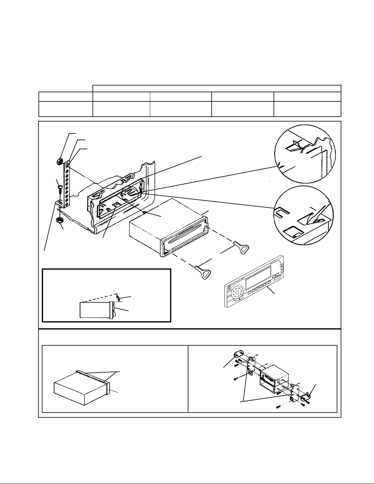
UNIVERSAL INSTALLATION USING MOUNTING SLEEVEUNIVERSAL INSTALLATION USING MOUNTING SLEEVE
UNIVERSAL INSTALLATION USING MOUNTING SLEEVE
UNIVERSAL INSTALLATION USING MOUNTING SLEEVEUNIVERSAL INSTALLATION USING MOUNTING SLEEVE
EXISTING DASH OPENING
FILE EDGES TO FIT IF NECESSARY - DO NOT OVERFILE
NOTE: IF DASH IS SOLID, USE REAR SIDE (WITHOUT THE LIP) OF MOUNTING SLEEVE
AS A TEMPLATE & CUT OPENING
SCREW STUD
RADIO
CENTRAL EASTERN
7:30AM - 6PM
8AM - 4PM
BEND TOP
TABS UPWARD
8:30AM - 7PM
9AM - 5PM
BEND BOTTOM TABS
DOWNWARD
FASTEN THIS END TO SECURE PART OF DASHBOARD.
DRILL HOLE IF NECESSARY.
FOR PROPER OPERATION OF THE CD PLAYER, THE CHASSIS MUST BE MOUNTED
WITHIN 20° OF HORIZONTAL. MAKE SURE THE UNIT IS MOUNTED WITHIN THIS
LIMITATION.
SIDE VIEW
OF
CHASSIS
REMOVE THE PLASTIC FRAME FROM THE FRONT OF THE CHASSIS BY
CAREFULLY UN-SNAPPING IT.
CAUTION:
20° MAX.
FRONT PANEL
UN-SNAP AT 2 PLACES EACH ON
TOP AND BOTTOM
PLASTIC FRAME
REMOVAL TOOLS
ISO INSTALLATIONISO INSTALLATION
ISO INSTALLATION
ISO INSTALLATIONISO INSTALLATION
MAXIMUM SCREW
FACTORY MOUNTING
BRACKETS
SIZE
M5 x 5MM
FOLD-DOWN
DETACHABLE
FRONT PANEL
TYPICAL INSTALLATION
MAXIMUM SCREW
SIZE
M5 x 5MM
-3-
Page 4
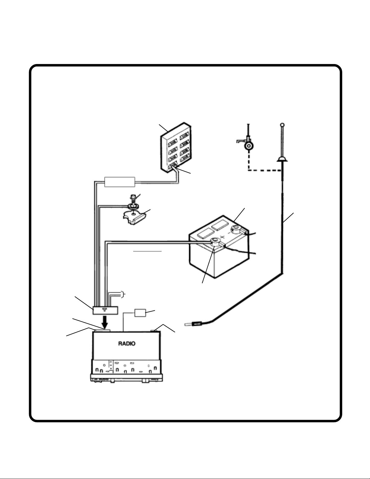
RADIO WIRINGRADIO WIRING
RADIO WIRING
RADIO WIRINGRADIO WIRING
REFER TO PAGE 5 FOR SPEAKER
WIRING
CAR FUSEBLOCK
AUTOMATIC
ANTENNA
ANTENNA
20-PIN HARNESS
CONNECTOR
20-PIN MATING
PLUG ON REAR
OF RADIO
10-AMP
PLUG-IN FUSE
RED
0.5 AMP
FUSE
SCREW
BLACK
YELLOW
IMPORTANT
THIS WIRE MUST BE CON-
NECTED AS SHOWN OR RADIO
WILL NOT OPERATE PROPERL Y
SEE PAGE 5 FOR
SPEAKER WIRING
METAL P AR T OF DASH
(DRILL HOLE IF NECESSARY)
EXTERNAL INVERTER
FOR VFD DISPLAY
BACKLIGHTING
“RADIO” OR
“ACCESSORY”
FUSE
POSITIVE (+) TERMINAL
12-VOLT BATTERY
ANTENNA SOCKET
ON REAR OF RADIO
CAR
BATTER Y
EXISTING ANTENNA
CABLE
-4-
Page 5
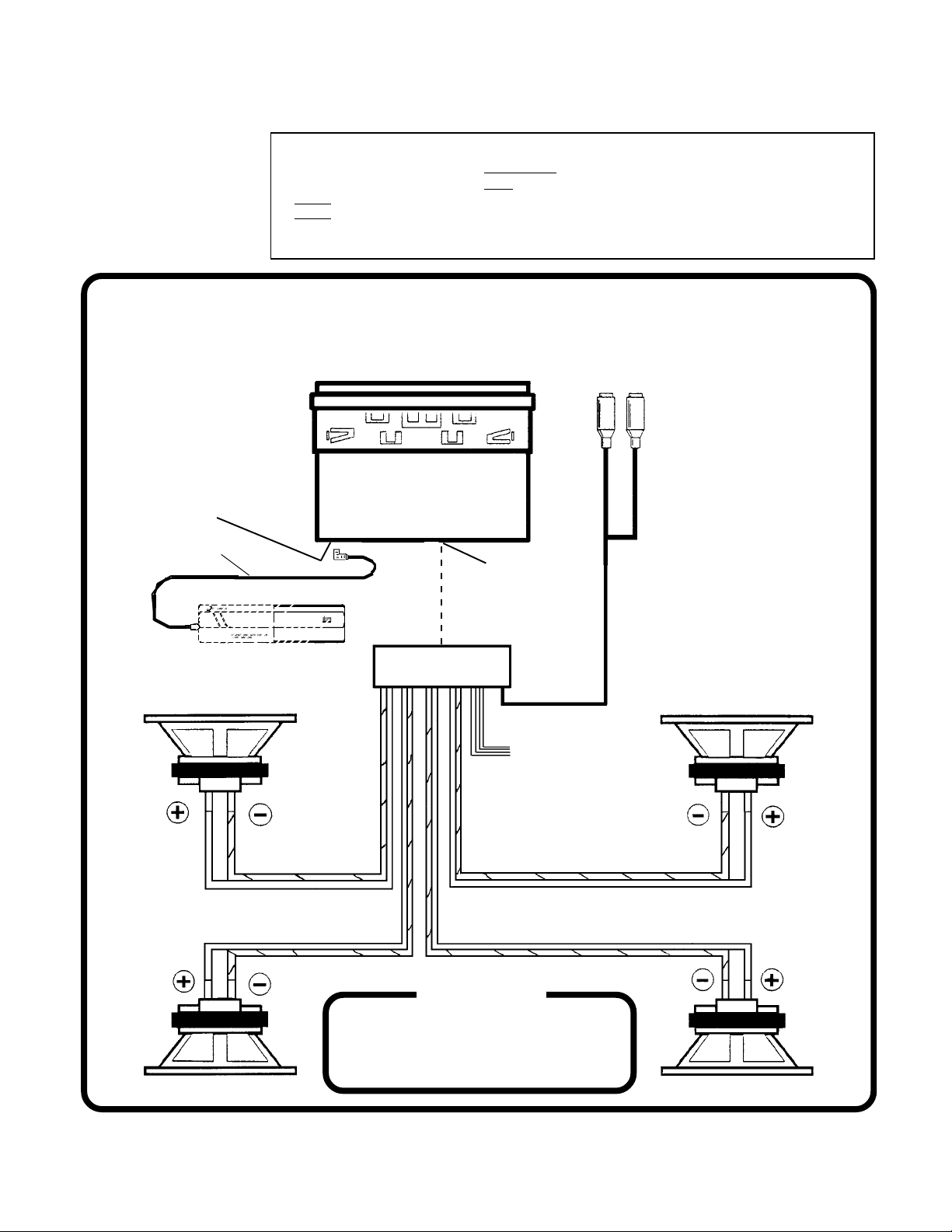
SPEAKER WIRINGSPEAKER WIRING
SPEAKER WIRING
SPEAKER WIRINGSPEAKER WIRING
REFER TO PAGE 4 FOR RADIO
WIRING
NOTE: CHECK WITH YOUR PRESTIGE/AUDIOVOX CAR
STEREO SPECIALIST OR CALL 1-800-645-4994 FOR
RECOMMENDATIONS OF THE CHANGER MODELS THA T
WILL WORK WITH YOUR RADIO.
8-PIN DIN SOCKET FOR
CONNECTION TO OPTIONAL
CD CHANGER
DIN CABLE (SUPPLIED
WITH CD CHANGER)
OPTIONAL CD CHANGER
6
WARNING!
l THE AMPLIFIERS IN THIS RADIO ARE ONLY DESIGNED FOR USE WITH 4 SPEAKERS.
l
NEVER COMBINE (BRIDGE) OUTPUTS FOR USE WITH 2 SPEAKERS.
l
NEVER GROUND NEGATIVE SPEAKER LEADS TO CHASSIS GROUND.
l FAILURE TO WIRE EXACTLY AS SHOWN BELOW MAY CAUSE ELECTRICAL
RCA LINE OUT JACKS FOR
USE WITH OPTIONAL
EXTERNAL AMPLIFIERS
RED------RIGHT REAR
WHITE---LEFT REAR
RADIO
20-PIN MATING
SOCKET
COMPACT
20-PIN INTERFACE
CONNECTOR
HELP!
1-800-645-49941-800-645-4994
1-800-645-4994
1-800-645-49941-800-645-4994
Monday - Friday
Saturday
RIGHT FRONT SPEAKERLEFT FRONT SPEAKER
SEE PAGE 4
FOR RADIO
WIRING
8:30am - 7:00pm Eastern
9:00am - 5:00pm Eastern
RIGHT REAR SPEAKERLEFT REAR SPEAKER
-5-
Page 6

© 2002 AUDIOVOX ELECTRONICS CORP., HAUPPAUGE, NY Printed in China
128-6301
 Loading...