

Page 1
OZO CAMERAOZO CAMERA
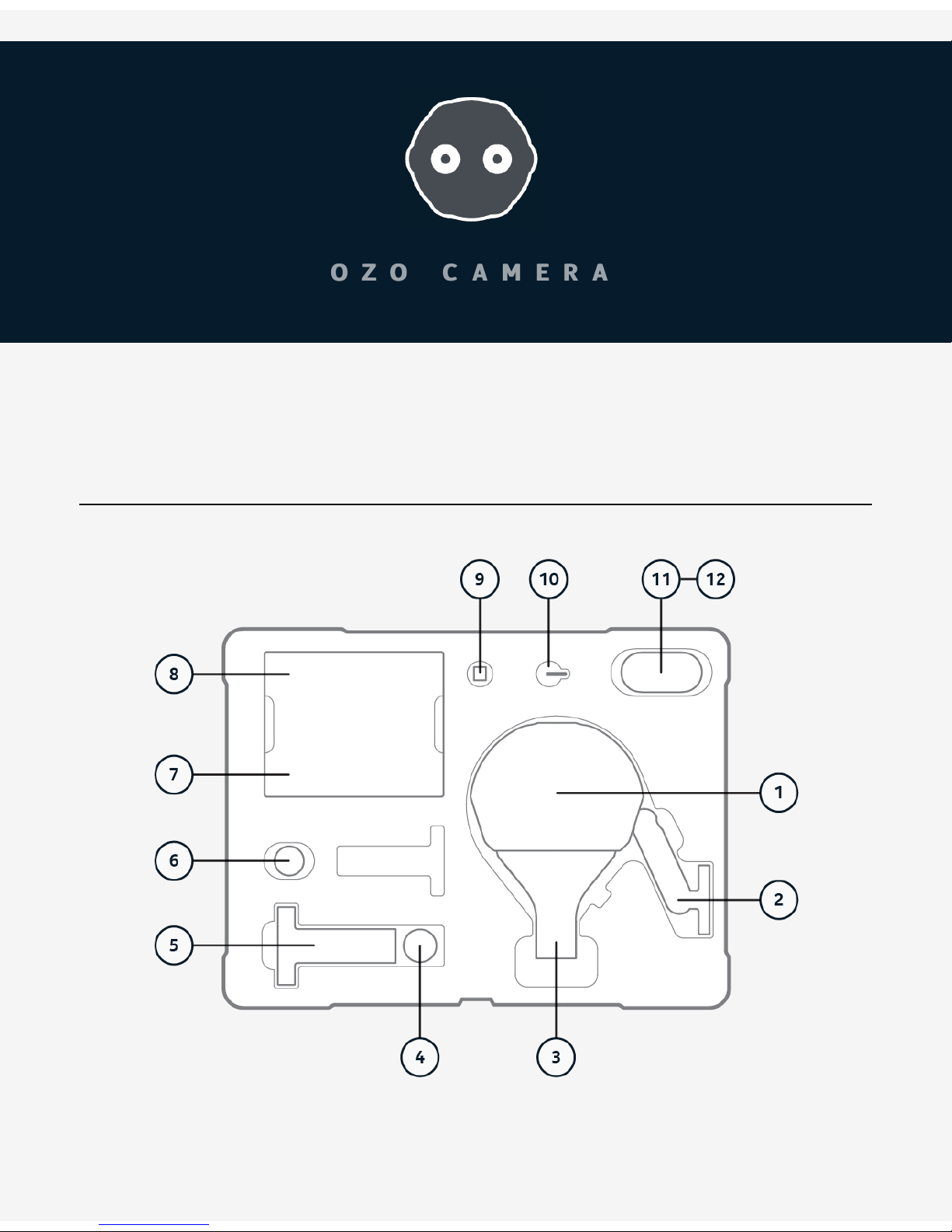
Box ContentBox Content
11.. Protective Cover (comes fitted to camera)
22.. Large tripod adapter (comes fitted to camera)
33.. OZO Professional VR Camera PC-01
Page 2
44.. Media Cable MC-01, for USB3 data transfer to computer directly from Media Module or
cartridge in Docking Station.
55.. Docking Station DS-01, for battery charging and data transfer
66.. Small tripod adapter
77.. Camera External AC power supply and AC cables
88.. Docking Station AC power supply and AC cables
99.. 3G-SDI adapter card in protective ESD bag, for external recording/monitoring
1010.. T6 tool, for removing Connector Cap of power/SDI slot
1111.. Digital Cartridge DC-01, including 33Wh Li-Ion rechargeable battery
1212.. Media Module MM-01, including 500GB solid state storage
The Protective NANUK 950 carrying case is intended for normal transportation of OZO and
included accessories. Please keep the cardboard shipping box and packing, and reuse when
transporting the camera by courier or shipping agent.
NOTE: Due to the size the case should travel as hold luggage when flying with OZO but the
cartridges (containing Li-Ion batteries) should be removed and carried as hand luggage
according to international regulations.
BASICSBASICS
Camera HandlingCamera Handling
Page 3
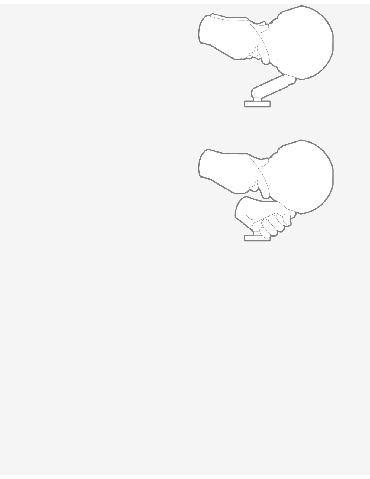
This is the most reliable way of handling the
device.
Lift the Camera at the "tail" applying a firm
and safe grip.
Additionally you can hold the device by the
OZO Tripod adapter if it is properly attached.
MountingMounting
Page 4
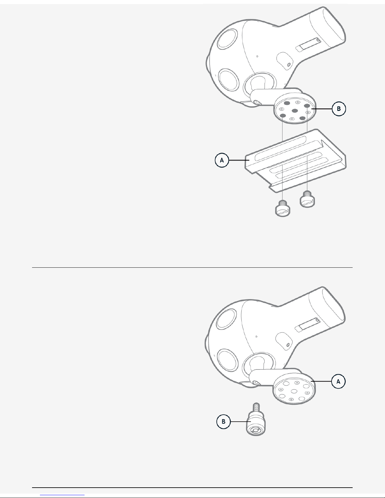
Securely mounting a base plate (A) to the
tripod adapter (B) is recommended.
The Device is delivered with the large OZO
Tripod adapter attached.
The large OZO tripod adapter includes 5 x
standard 3/8" tripod mounting hole.
The included alternative small OZO tripod
adapter includes 1 x standard 3/8" tripod
mounting hole.
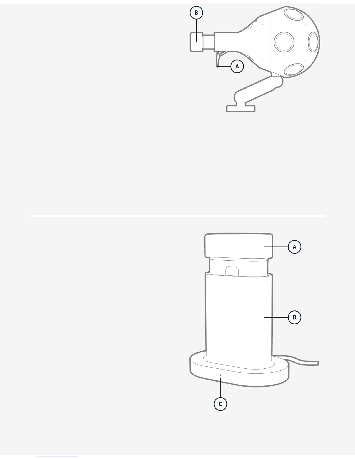
Changing the Tripod AdapterChanging the Tripod Adapter
Specific force is required to ensure the newlyattached tripod adapter is securely fixed.
1. Carefully remove the mounted adapter (A)
using an M8 tool.
2. Attach the alternative adapter (B).
3. Apply exactly 20 Nm with a torque wrench
tool and fix securely. Do not overtighten.
Do not replace the M8 screw.
If damaged, always replace with original spare
parts.
Connector Cap RemovalConnector Cap Removal
Page 5
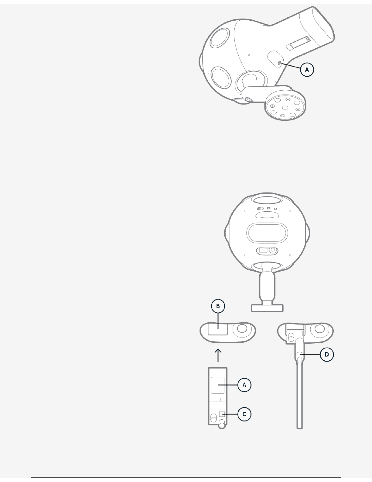
For streaming data through SDI and supplying
external power, remove the connector cap (A)
located below the "tail" section by using the
provided T6 Torx tool.
For stand alone use, place the connector cap
back in the slot and tighten by hand without
excessive torque.
This cap provides basic sealing and protection
for the SDI and power connectors.
Connecting SDIConnecting SDI
Attaching 3G-SDI card Carefully remove the
3G-SDI SFP+ card (A) from the ESD bag, and
insert it firmly into the SFP+ socket (B).
To remove, lift the latch (C) on the SDI card
and carefully apply backwards pressure to the
frame of card, NOT to the DIN sockets.
Attaching SDI DIN cable Attach a standard SDI
DIN connector (D) to the lower DIN socket
shown by arrow facing away from device.
To remove the cable, lift the cover of the DIN
connector, and apply pressure.
Take care not to apply lateral force to the DIN
sockets. Use cable strain relief where
necessary, otherwise damage may occur.
Connecting PowerConnecting Power
Page 6
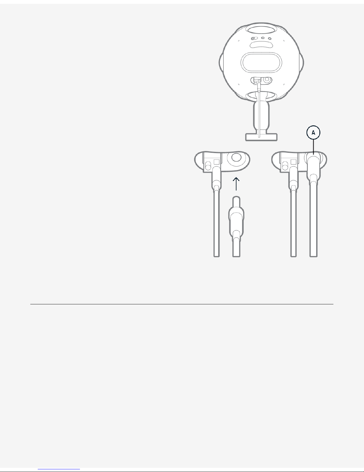
Insert the external power plug into the device
firmly, and rotate the lock ring (A) clockwise
until it is tight.
Always ensure the external plug is fully
inserted, otherwise the device may not power
up, or may use battery power only.
Cartridge ReplacementCartridge Replacement
Page 7
Before you start make sure the device is
stable and mounted correctly.
1. Pull the latch (A) to it's full extension to
release the cartridge. Do not pull the cartridge
while doing so.
2. Pull the cartridge (B) out (and close the
latch).
3. To insert the cartridge pull the latch to it's
full extension.
4. Insert the cartridge with the groove
pointing downwards until you notice
resistance.
5. Release the cartridge and close the latch.
Charging BatteryCharging Battery
Insert a Digital Cartridge (A) into the Docking
Station (B).
Ensure a power cable is connected to the
Docking Station.
The LED on the Docking Station (C) should
flash white to indicate charging is in progress,
and show solid white to indicate when the
Digital Cartridge battery is fully charged.
Charging an empty battery can take up to 3
hrs.
A Digital Cartridge must be inserted at least
once to a powered Docking Station before it
can be used in the device.
A red light indicates a problem. Slow flashing
red indicates "No Battery found". Solid red
indicates "Cannot charge" (broken or
misplaced battery). Fast flashing red indicates
a malfunction.
Page 8
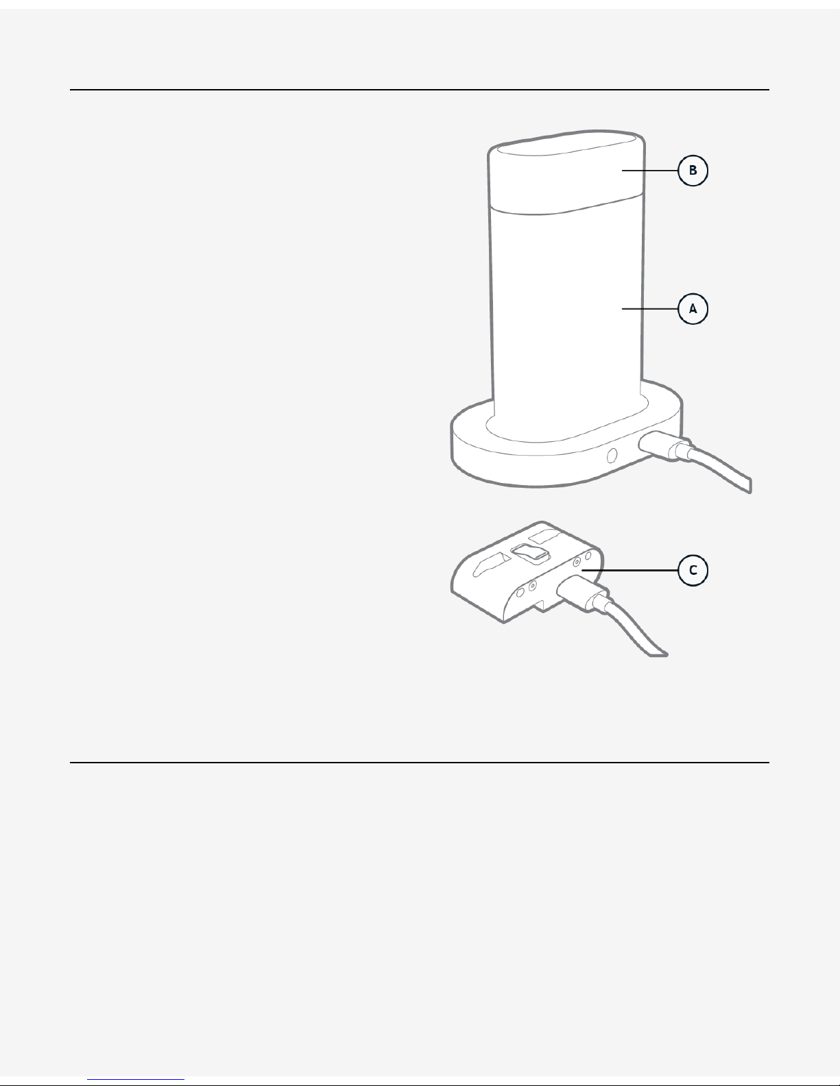
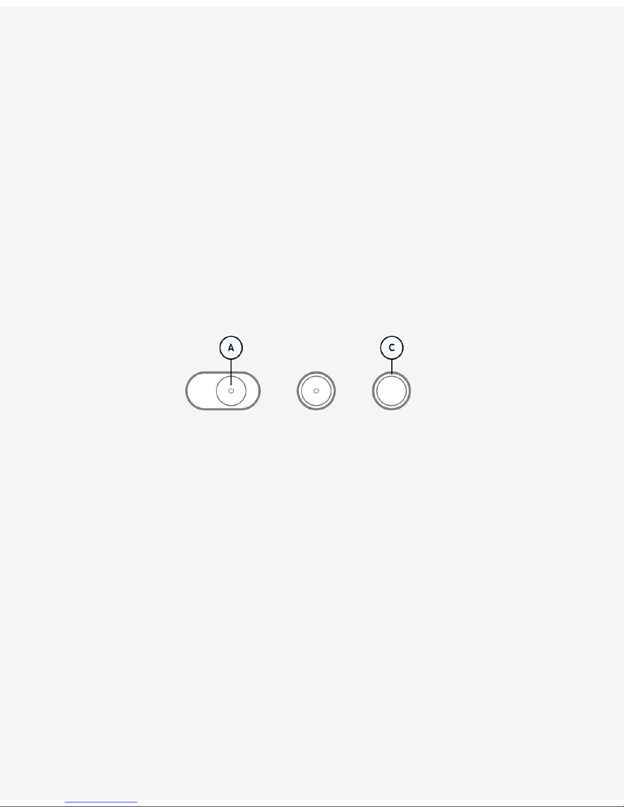
Extracting DataExtracting Data
Connect the supplied USB cable from the
Docking Station (A) to a computer with the
OZO Creator application installed.
Insert the Digital Cartridge (B) with a Media
Module inside.
Alternatively, connect the supplied USB cable
directly between a Media Module (C) and the
computer.
OZO ApplicationsOZO Applications
Page 9
To download and install the OZO Applications
please follow the instructions on
ozo.nokia.com/start.
The OZO Remote Application is needed for
example to set and monitor the exposure of
the OZO Camera.
The OZO Creator Application is used to
process and deploy the captured content to
post production tools.
The OZO Preview Application is a tool to
quickly access and view rendered content like
editorials for audio mixing.
OZO Applications require an Apple Mac Pro®
6-Core Dual GPU using OS X 10.10 Yosemite
or newer.
Basic OperationBasic Operation
Page 10
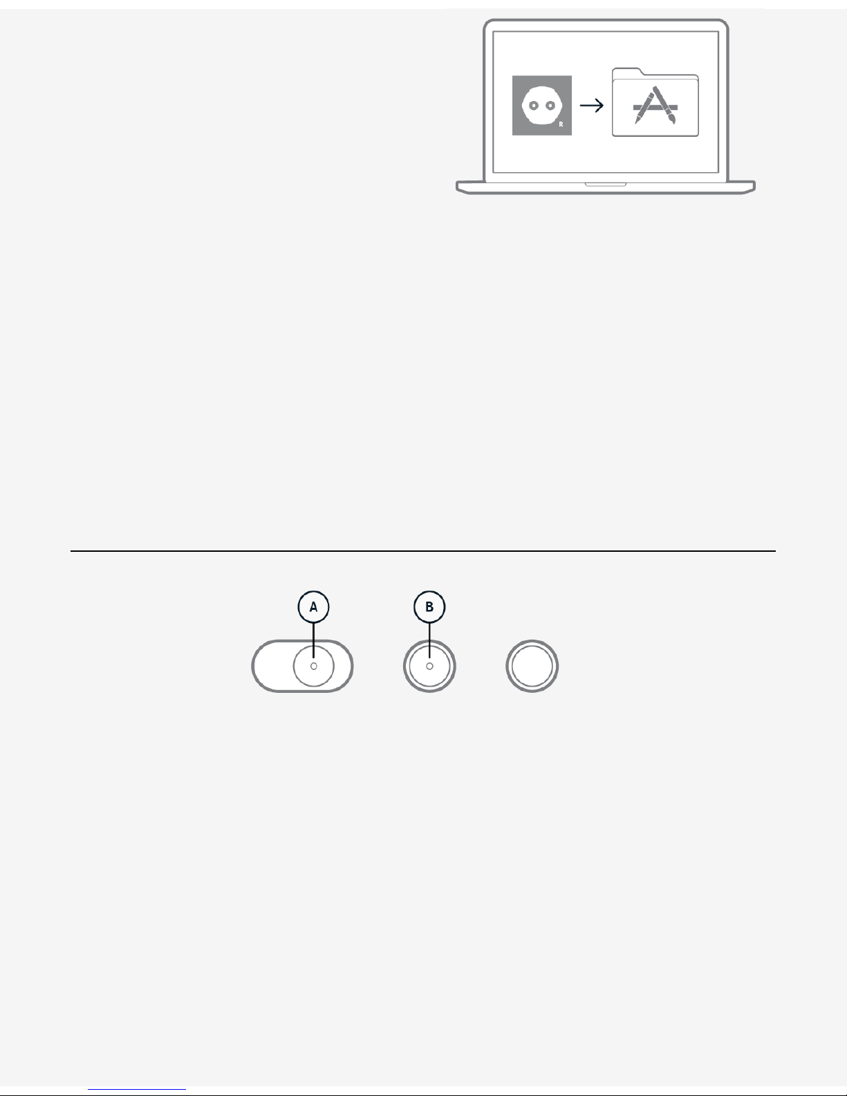
Power ON-OFF
To power on the device slide the power
button (A) to the outmost right position and
release. The button will stay in an intermediate
position and the indicator (LED) in the center
of the button indicates booting (by blinking
slowly).
Once the booting has finished the indicator
discontinues blinking and remains lit. The
device always boots into "Broadcasting" mode
to allow immediate preview over SDI.
For complete shutdown slide the power
button to the outmost left position.
WiFi
By default the device is enabling WiFi
immediately after booting is complete. The
WiFi-LED (B) is blinking slowly to indicate
readiness to connect.
The OZO Remote host computer must have
WiFi enabled to connect to the OZO Camera.
The WiFi-button indicator discontinues
blinking and remains lit to indicate a
successful connection to the OZO Remote
Application.
To boot the device without WiFi (airplane
mode) press and hold the WiFi button during
startup until booting has finished.
Page 11

Oculus Rift DK2 SetupOculus Rift DK2 Setup
1. Download and install Oculus Runtime for OS X version 0.4.4-beta from:
https://developer.oculus.com/downloads/pc/0.4.4-beta/Oculus_Runtime_for_OS_X/
2. After installing the Runtime connect the Oculus DK2 HDMI and USB cables to your Mac.
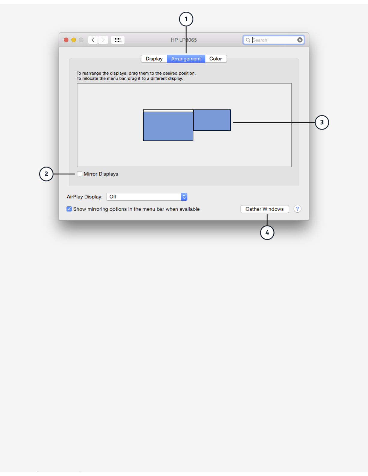
3. Having connected the DK2 open the Display settings from the System Preferences (click the
Apple logo in the top-left-corner of your display).
4. Select the Arrangement tab (1) and make sure the "Mirror Displays" (2) checkbox is
unchecked, and the Rift DK2 display is positioned on the right side of the main display (3). The
size of the main display may vary depending on your display resolution.
NOTE: You can have only one main display, and no additional secondary displays connected
when using OZO applications with the Oculus Rift DK2.
Broadcasting over SDI
You can switch from Standby-mode to
Broadcasting either by sliding the powerbutton (A) to the outmost right position and
release (as you did for power on) or by using
the controls in the camera-mode panel of the
OZO Remote Application.
Repeat this procedure to return back to
Standby mode.
During Broadcasting a red LED ring around the
Capture-button blinks regularly "once in a
while" to indicate that the Camera is "On the
Air".
To monitor the live image from the Camera
make sure the SDI adapter and cables are
connected to your OZO Remote host
computer.
Use the Capture Settings panel in OZO Remote
to set the exposure.
Capturing
Press the Capture button to start or stop
capturing to the internal storage.
While capturing to the internal Media Module
the Capture button indicator (C) is
continuously on. Blinking slowly signals "less
than 5 minutes left".
Blinking fast signals "storage is full". These
limits are also reflected in the "Storage" status
group in OZO Remote.
NOTE: To capture on external storage set the
Camera to Broadcasting instead and use the
controls on the external device.
Page 12
Note: The Rift DK2 display may be in portrait orientation and it must be rotated to landscape
orientation. This gets fixed by applying the correct settings:
5. Click the "Gather Windows" button (4) to bring the "Rift DK2" settings window to the main
display and apply these following settings (5) to (7):
Resolution: Best for display/ Rotation: 90°/ Refresh Rate: 75 Hertz
Page 13

6. After changing the settings, you might need to click "Gather Windows" (8) again to access the
Rift DK2 settings. You need to confirm (9) the changes within 15 seconds to keep them.
Page 14

Compatible SDI AdapterCompatible SDI Adapter
OZO can be used together with Blackmagic SDI adapters. The adapter requires driver installation
only. No additional setup is needed. Please visit https://www.blackmagicdesign.com/support for
download and support.
Page 15

REMOTEREMOTE
IntroductionIntroduction
OZO Remote is an application that allows you to remotely and wirelessly control the OZO Camera
and live preview captures. It is needed, for example, to set and monitor the exposure of the OZO
Camera.
The application is composed of two main areas:
The column on the left side of the window focuses on the connection, control and monitoring of
the Camera. It is composed of different panels that you can open and close at will depending on
your needs.
The big area on the right is focused on the preview of the SDI signal provided by the Camera.
The control of the Camera happens via Wi-Fi, while the preview is done via SDI cables. The
intended setup is to connect WiFi and SDI both to the same OZO Camera.
Connecting WiFi and SDI each to different Cameras is theoretically possible but not intended.
Please observe the application as it may appear dysfunctional with that setup.
OZO Remote is also used to format the OZO Media Module in the Camera.
Controlling the OZO CameraControlling the OZO Camera
You can control the Camera with the panels located on the left side of the window. Different
elements are provided to connect, change the capture settings, capture and monitor the battery
and storage levels of the Camera.
Connecting to and Disconnecting from Camera via WiFiConnecting to and Disconnecting from Camera via WiFi
Make sure the OZO Camera is powered on and that your computer has Wi-Fi enabled. The
Camera will appear in OZO Remote in the panel of OZO devices. The panel includes both
currently available and previously connected Cameras.
Page 16

Click on the Camera in the panel to connect.
To disconnect, use the command "Disconnect" from the "Connection" menu.
The wireless range will depend on the operating environment, and is consistent with other Wi-Fi
802.11 systems, that is typically 50-200 ft (15-16-m).
Broadcasting and StandbyBroadcasting and Standby
OZO Cameras can be in broadcasting or standby mode. In broadcasting mode, video is sent out
over SDI. In standby, the Camera is in low energy consumption mode and video is not sent out.
When the device is powered on, it is automatically set to broadcasting mode by default. To
switch between these modes, click on the Camera mode button.
CapturingCapturing
To start and stop capturing with the connected Camera, click on the Capture button in the
Camera Mode panel.
Captures will be stored in the internal SSD of the connected Camera.
Illuminant SettingIlluminant Setting
To set the illuminant of the connected Camera use the Illuminant control in the Capture Settings
panel.
This illuminant is set on the Camera and will be used while capturing. Alternatively, if you want to
change the illuminant only for preview purposes without affecting the Camera illuminant setting,
use the preview illuminant setting located in the monitoring area.
Exposure SettingExposure Setting
To set the exposure of the connected Camera use the Exposure control in the Capture Settings
panel.
Power StatusPower Status
To monitor the usage of the power, open the Power panel.
The Power panel indicates if the Camera is currently plugged to external power or using the
battery in the Digital Cartridge.
The panel provides the remaining battery level in any case, but observe that the battery gets recharged only with the OZO Docking Station.
StorageStorage
Page 17

To monitor the usage of the SSD, open the Storage panel.
The panel displays information about the remaining capture time or capacity. To toggle between
these options, click on the indicator.
You will be alerted when running out of storage.
Temp e ra tu reTemp e ra tu re
To monitor the temperature of the device, open the Temperature panel.
The panel displays information about the current temperature in °F or °C. To toggle between
these options, click on the indicator.
You will be alerted when reaching the overheating limits .
Audio GainAudio Gain
Audio monitoring gain can be used to change the loudness of the monitored spatial audio.
Please note that this setting does not affect the stored audio. Instead, audio is always stored
with full dynamic range.
Monitoring the SDI SignalMonitoring the SDI Signal
The tools located on the right area allow to monitor the SDI signal broadcasted by the OZO
Camera. The tools include alternative ways to view the signal, clipping indicators and preview
illuminant.
SDI SignalSDI Signal
The SDI signal is provided by the connected OZO Camera. If the SDI signal is not displayed by
OZO Remote, make sure the SDI cables are properly attached to the Camera, an SDI adapter has
been set up in your computer and the connected OZO Camera is in broadcasting mode.
Channel GridChannel Grid
The streams from the 8 lenses of the Camera are displayed in native equidistant fisheye
projection mode by default. This allows previewing all angles of the video streams.
The rectilinear mode is used when objects in the scene need to be monitored in their natural
appearance.
To switch to rectilinear mode, use the toggle buttons in the toolbar or the "Rectlinear View"
command in the "View" menu.
Page 18

Double-clicking on any stream enters or exits the single Camera mode.
Combining the rectilinear and single Camera mode allows free panning through the scene.
Live Preview with Oculus Rift DK2Live Preview with Oculus Rift DK2
OZO Remote supports interactive Live Virtual Reality Preview with an Oculus Rift DK2 headset.
Follow the headset setup instructions to use it with OZO Remote.
You can toggle the preview between your computer display and the headset with the HMD
button in the toolbar or the "View in HMD" command in the "View" menu.
Toggling to HMD is disabled if the headset has not been installed in the computer, it is not
connected at that moment or there is no SDI signal to preview.
Preview IlluminantPreview Illuminant
The preview illuminant changes the illuminant for preview purposes without affecting the
Camera illuminant setting. This can be useful if multiple OZO Remote instances are being used
for monitoring the same Camera at the same time.
To enable the visual override of the Camera illuminant, toggle the preview illuminant button on.
Then select the preview illuminant from the adjacent control.
Although changing the Camera illuminant setting is faster with the Illuminant Setting control in
the Capture Settings panel, it is also possible to apply the preview illuminant to the Camera
illuminant with the "Apply to Camera" button.
To disable the visual override of the illuminant, just toggle the preview illuminant button off.
Clipping and ZebraClipping and Zebra
Clipping indicators are useful tools to set the exposure.
The preview toolbar provides 3 controls for lowlight clipping, highlight clipping and a custom
zebra midband.
Hovering on any of these controls will show the clipped areas in the lenses views. Clicking on the
controls will toggle them on so the clipped areas will be shown permanently until toggled off.
To change the range of the zebra midband use the adjacent control.
Freezing the ImageFreezing the Image
To freeze the video and get a high resolution image, use the freeze button in the toolbar or use
the "Freeze" command in the "View" menu.
To unfreeze the image and resume to live signal, use the same button.
Page 19

Managing the OZO Camera SettingsManaging the OZO Camera Settings
OZO Remote can be used to upgrade the Camera firmware and calibration file.
Firmware UpgradeFirmware Upgrade
It is important to keep the firmware updated with the latest releases to ensure the device
operates with optimum stability and performance.
Assuming an internet connection is available, OZO Remote informs whenever a new firmware is
available for upgrade. Additionally, you can check the current firmware version of the Camera
and upgrade if available in the application Preferences.
Calibration File UpgradeCalibration File Upgrade
Calibration files are needed to optimize the quality of the captured media.
In order to ensure the optimum results, it is important to keep the calibration files updated to
the last version.
Use the application Preferences window to check the current calibration file number of the
Camera and upgrade.
UninstallingUninstalling
To uninstall OZO Remote from your computer, run OZO Uninstaller located in Applications > OZO
> Utilities.
CREATORCREATOR
Page 20

IntroductionIntroduction
The OZO Creator Application is used to process and deploy the captured content to post
production.
OZO Creator uses a project-based approach that allows the user not only to import, preview and
export assets but also to cut and render simple compositions for the purpose of previewing
content in production.
A Stage is used to collect assets into the project. Items on the Stage are mainly previewed or
exported to other post-production tools. Processed assets can also be re-imported for further
analysis or distribution.
The timeline composition tool acts as multi-purpose cutting table. This tool can for example be
used to compare clips or to layout storylines for audio mixing.
ProjectsProjects
The purpose of projects is to organize files as collections of assets that relate to each other.
Each project has a timeline where these assets can be combined into stories.
ImportingImporting
WorkflowWorkflow
The basic OZO Creator workflow of managing assets starts by importing files that were captured
by the OZO Camera on either the OZO Media Module or an external drive to the Stage.
To import assets to the Stage you can use any of the import options in the "Stage" menu (or the
import-button below the Stage).
Processing FilesProcessing Files
Files on external drives are stored in the .mov format while files on the Media Module are stored
in a proprietory format called .ozoraw. Importing these formats to the Stage automatically
applies a basic processing that is required to later export or use the files on the Timeline.
Page 21

Re-importRe-import
For further analysis or rendering of content previews OZO Creator allows the re-import of
postprocessed DPX files with according metadata as well as multi-channel .wav audio files.
ExportingExporting
To export a selected item from the stage go to the "Stage" menu and choose "Asset" >
"Export".
Export OptionsExport Options
OZO Creator is optimized for exporting standard DPX with metadata.
It also offers an export-option for a "flattened" 360° editorial which includes optional visual
overlays to facilitate spatial audio mixing. The editorial can be imported to digital audio
workstations.
Spatial audio captured with the OZO Camera can be exported as loudspeaker signals. OZO
Creator automatically processes the spatial audio for the selected loudspeaker layout.
Supported Loudspeaker LayoutsSupported Loudspeaker Layouts
11.. 4.0: 45, -45, 135, and -135 degrees
22.. 5.0: 30, -30, 0, 110, and -110 degrees
33.. 7.0: 30, 0, -30, 90, -90, 150, and -150 degrees
44.. 8.0: 0, 45, 90, 135, 180, -135, -90, and -45 degrees
Note: The channel order has to match these layouts for correct processing.
Rendering PreviewsRendering Previews
Rendered previews is a convenient way to share the content among stakeholders.
The OZO Preview application allows viewing those previews without having to install OZO
Creator.
Page 22

Preview and AnalysisPreview and Analysis
A selection on the Stage or Timeline is automatically made available for preview. The playback
controls provide the basic means to play, pause and skip between logical keypoints. Paused
frames are automatically rendered for High Resolution preview.
Asset previewing and Timeline previewing are using dedicated rulers and playheads to make
switching back and forth between them more convenient.
View ModesView Modes
The preview area provides several view modes for specific needs. The default view mode
monitors all video streams separately in undistorted full angles (fisheye mode).
The rectilinear mode is used when objects in the scene need to be monitored in their natural
appearance.
Double-clicking on any stream enters or exits the single camera mode.
Combining the rectilinear and single camera mode allows free panning through the scene.
Clipping and ZebraClipping and Zebra
Clipping is instantly visualised by hovering over the clipping controls or toggling them on/off. The
threshdold for high and low clipping indication is 3% luminance.
Once enabled the midrange "Zebra" can be adjusted by clicking on the range indicator.
Composing a ClipComposing a Clip
Adding Items to the TimelineAdding Items to the Timeline
The easiest way to add items to the timeline is drag and drop them from the stage.
When you add an audio file to the timeline it will automatically become attached to the closest
video item. Attaching an audio item always replaces the existing audio in that spot.
Removing Items from the TimelineRemoving Items from the Timeline
To remove an item simply select and delete.
Page 23

Tri m mi n g I n /Ou tTri m mi n g I n /Ou t
Precise trimming of an item on the timeline is done by positioning the playhead and using the
trim-buttons.
A quick way is to use the items in and out handles.
Setting the timeline in and out is currently only done by dragging the timeline handles.
PREVIEWPREVIEW
OZO Preview is a simple application that allows you to play previews rendered by OZO Creator
without the need to install the latter.
Files and FormatsFiles and Formats
OZO preview currently only allows to preview files rendered with OZO Creator.
Click on the "Open file" button after the application is launched or the "Open..." command in the
"File" menu at any time to select and open an OZO preview file.
Because it is a single window application, OZO Preview can play only one preview file at a time.
ViewingViewing
OZO preview files can be experienced in time and view direction .
Page 24

Preview with Oculus Rift DK2Preview with Oculus Rift DK2
OZO Preview supports Virtual Reality Preview with an Oculus Rift DK2 headset.
Follow the headset setup instructions to use it with OZO Preview.
You can toggle the preview between your computer display and the headset with the HMD
button in the toolbar or the "View in HMD" command in the "View" menu.
Time: Playing, Pausing and SeekingTime: Playing, Pausing and Seeking
Basic playback controls are provided in the toolbar at the bottom of the window:
The "Stop" button sets the playhead to the beginning and stops the playback.
The "Play" button starts or resumes the playback of the file if stopped or paused. While playing,
it toggles into a "Pause" button, which pauses the playback.
The "Progress bar" allows to jump quickly into different times of the preview file.
The timestamp in the bottom toolbar provides info about the lenght of the preview file and the
current position of the playhead.
Arrow keys are used for fine control of the playhead. Left and right keys move playhead 1 frame
back and forward, while up and down keys move 1 second.
View DirectionView Direction
You can change the viewing direction by panning the content of the preview window or by
moving the headset.
To go back to the 0-degree view at any moment, use the "Center View" command in the "View"
menu.
Midi ControlMidi Control
Midi control can be used to start OZO Preview playback from digital audio workstations (DAW)
when they are running in different computers in the same network. This enables you to have
audio playback from DAW and video playback from OZO Preview in sync.
To use this feature with ProTools, first make sure "Network midi" is set up in "Audio Midi Setup"
in OS X preferences and that in OZO Preview "MTC Sync" command in "View" menu is enabled.
Then do the following in ProTools:
11.. Set up your session ("Setup" > "Session") to start at 00:00:00:00.
22.. In "Setup" > "Peripherals...", set the MTC Generator to be your network session.
33.. Go to the next tab "Machine Control" and enable the master.
Page 25

44.. Select your network midi session.
55.. In "Setup" > "Preferences", go to the "Synchronization" tab and activate both "Machine
Chases Memory Location" and "Machine Follows Edit Insertion/Scrub".
66.. In your transport controls activate "GEN MTC".
You might need to adapt your project to account for ˜600ms of startup buffering latency of the
player, after which the content should be in sync.
KEYBOARD SHORTCUTSKEYBOARD SHORTCUTS
Shared ShortcutsShared Shortcuts
ApplicationApplication
Remote Creator Preview
Preferences • • Cmd + ,
Hide application • • • Cmd + H
Hide others • • • Alt + Cmd + H
Quit application • • • Cmd + Q
ViewView
Page 26

Remote Creator Preview
Show / Hide clipping low • • Cmd + [
Show / Hide clipping high • • Cmd + ]
Show / Hide midrange • • Cmd + /
Toggle rectilinear/fisheye view • • V
Center rectlinear or HMD view • • • C
Toggle HMD/screen view • • • H
Toggle enter/exit full screen • • • Ctrl + Cmd + F
In single viewfinder mode, go to
previous
• • Cmd + Left
In single viewfinder mode, go to next • • Cmd + Right
In single viewfinder mode, go back to
grid
• • Esc
WindowWindow
Remote Creator Preview
Close • • • Cmd + W
Minimize • • • Cmd + M
HelpHelp
Remote Creator Preview
Application help • • • Cmd + ?
TimelineTimeline
Page 27

Remote Creator Preview
Move 1 frame backward • • Left
Move 1 frame forward • • Right
Move 1 second backward • • Up
Move 1 second forward • • Down
OZO Remote ShortcutsOZO Remote Shortcuts
ConnectionConnection
Disconnect Alt+ Cmd + K
ViewView
Toggle preview illuminant Cmd + L
Freeze video Space
OZO Creator ShortcutsOZO Creator Shortcuts
ProjectProject
New Cmd + N
Open Cmd + O
Save Cmd + S
Page 28

Save as shift + Cmd + S
EditEdit
Undo Cmd + Z
Redo Shift + Cmd + Z
Cut Cmd + X
Copy Cmd + C
Paste Cmd + V
StageStage
Import capture Cmd + I
Import DPX Shift + Cmd + I
Import audio Alt + Cmd + I
Export selected asset Alt + Cmd + E
Render selected asset Alt + Cmd + R
TimelineTimeline
Remove space Cmd + Backspace
Toggle snap Shift + Cmd + '
Export Cmd + E
Render Cmd + R
Play / Pause playback Space
Zoom in Cmd + +
Page 29

Zoom out Cmd + -
Default zoom Cmd + 0
OZO Preview ShortcutsOZO Preview Shortcuts
FileFile
Open Cmd + O
ViewView
Toggle Loop L
Mute / Unmute audio M
Show / Hide info overlay I
Disable / Enable MTC sync T
WARNINGSWARNINGS
Page 30

VentilationVentilation
Do not cover the ventilation opening (A).
The Device is cooled by air flowing between
the outer and inner structure.
Keep the device ventilation upright (B).
Covering the opening or mounting the device
in a way that the openings are not vertically on
top of each other would prevent the air from
flowing.
OverheatingOverheating
Page 31

Capture or broadcast will stop on overheat.
The Device is protected against overheating
by switching to standby when the temperature
of the device exceeds a set limit (A).
Switching to standby discontinues any kind of
capturing because the sensors are powered
down.
If the temperature continues to rise even after
switching to standby a second threshold
triggers full shutdown (B).
Do not use near heat sources.
These may cause the device to overheat, and
stop capture.
TemperatureTemperature
Page 32

Operating TemperatureOperating Temperature
The device should only be used between
+32°F and +77°F (0°C and +25°C). Do not use
outside this range.
Storage TemperatureStorage Temperature
The device should be stored between -4°F and
+122°F (-20°C and +50°C). Do not store
outside this range.
+32°F / +77°F 0°C / +25°C
-4°F / +122°F -20°C / +50°C
Protective CoverProtective Cover
Page 33

Do not remove the protective cover until the
device is fully mounted.
Keeping the protective cover on the device for
as long as possible decreases the risk of lens
damage significantly.
To remove or attach the cover, open it only
the necessary amount.
Avoid contact with the lenses as much as
possible.
Safety and HandlingSafety and Handling
Page 34

Handle with care.
The device weight is 4.2 kg (9.3 lbs) including
the digital cartridge.
Do not lift the device by holding the protective
cover or cartridge.
Do not manipulate the device without the
protective cover.
Care should be taken when moving the device.
Do not place or mount the device on unstable
objects.
To avoid damage to the device, remove and
insert the Digital Cartridge according to the
instructions given in the section "Cartridge
replacement" p. 21.
To avoid damage to the 3G-SDI card, attach
and remove SDI cables according to the
instructions given in the section "Attaching
SDI DIN cable" p. 19.
Mount correctly.
The device must be mounted securely before
use according to the instructions given in the
section "Mounting" p. 16.
Failure to mount securely could cause damage
to the device, or injury.
Specific tools and the correct amount of
torque must be used when changing the
tripod adapter.
Do not place or mount the device on vibrating
or oscillating objects as this may cause
mechanical failure.
General WarningsGeneral Warnings
Do not drop the device.Do not drop the device.
If the device is dropped, it may be damaged or
modified externally or internally and become
unusable for the intended purpose.
After dropping, in case of damage or incorrect
operation, please contact the manufacturer
for (non-warranty) repair. Take care to avoid
injury if glass lenses become broken.
Water / humidityWater / humidity
Do not use in or near water. The device is not
waterproof, and may be damaged if used
underwater, in rain, or in environments with
BatteryBattery
Do not disassemble or open, crush, bend or
deform, puncture, or shred.
Do not modify or remanufacture, attempt to
insert foreign objects into the battery,
immerse or expose to water or other liquids,
or expose to fire, explosion, or other hazard.
Only use the battery for the system for which
it was specified.
Only use the battery with a charging system
that has been qualified for use with the
system. Use of an unqualified battery or
Page 35

high moisture or humidity.
Repairs / opening the deviceRepairs / opening the device
Repairs should be performed only by qualified
service personnel. Do not attempt to open the
device, as this may cause damage which will
void the warranty.
Power sourcePower source
Use only the supplied power sources. Take
precautions when handling power plugs. Do
not use with power outlets or extension cords
if they are overloaded, dusty, wet or physically
damaged.
CablesCables
Do not use the supplied USB cable to directly
connect two computers, as this may cause
damage. Do not walk or step on cables. Do not
place heavy objects on cables. Do not twist
cables.
charger may present a risk of fire, explosion,
leakage, or other hazard.
Do not short circuit a battery or allow metallic
or conductive objects to contact the battery
terminals.
Please contact the manufacturer for (nonwarranty) repair to replace the battery with
another battery that has been qualified with
the system. Use of an unqualified battery may
present a risk of fire, explosion, leakage, or
other hazard.
Do not insert a fully charged battery into the
charger repeatedly. Due to the high initial
charge, the battery could be overcharged
which could lead to damage to the battery and
to the battery charger.
Promptly dispose of used batteries in
accordance with local regulations.
Battery usage by children should be
supervised.
The battery should only be charged or used by
a compatible device or charger, and will fail to
operate if inserted to an incompatible system.
Avoid dropping the battery. If the battery is
dropped, especially on a hard surface and you
suspect damage, take it to a service center for
inspection. Improper battery use may result in
a fire, explosion, or other hazard.
WARRANTY AND LEGALWARRANTY AND LEGAL
Page 36

WarrantyWarranty
WARRANTY, WARRANTY LIMITATIONS AND WARRANTY DISCLAIMER.WARRANTY, WARRANTY LIMITATIONS AND WARRANTY DISCLAIMER.
Subject to the limitations and disclaimers setforth below, Nokia warrants that the productsshall
be of good quality and free from defects in material and workmanship. Upon the expiration of
the time periods set forth below, all liabilities of Nokia will terminate.
Standard Product WarrantyStandard Product Warranty
A standard product warranty is granted to the original Buyer by Nokia for a period of one (1)
year, parts and labor, for the camera, excluding the batteries. ("Standard Product Warranty") The
standard warranty for batteries is ninety (90) days from the date of delivery of the products to
Buyer. This Standard Product Warranty covers parts and labor charges for products that have
been returned pre-paid shipment to Nokia, a Nokia Reseller or Nokia authorized service center,
as directed by Nokia. All warranty returns shall be done in accordance with Nokia's return
materials authorization ("RMA") process. Any repaired or replaced product shall be warranted for
a period the greater of (i) the balance of the applicable warranty period relating to such Product
or (ii) ninety (90) days after it is received by Buyer. Only the components that were repaired or
replaced will be eligible for the 90-day period as set forth above. The Standard Product Warranty
effective date is the date the product was received by Buyer or Reseller (if purchased for
Reseller's own use).
Product Warranty LimitationsProduct Warranty Limitations
All Nokia warranties exclude the following:
1. Maintenance, repair or replacement necessitated by loss or damage resulting from any cause
other than normal use and operation of the product in accordance with the Nokia's
specifications and product manual, including but not limited to: theft, exposure to weather
conditions, use of the product underwater or in wet environments, operator negligence, misuse,
abuse, improper electrical/power supply;
2. Alterations, modifications or repairs by Buyer or unauthorized third parties;
3. Accident, disaster, improper handling or storage, droppage, modification to the camera,
opening the camera body, use third party accessories or acts of nature or any other peril
originating from outside the product;
Page 37

4. Transportation damage (except for transportation damaged in delivery of the products to
Buyer from Nokia), lack of maintenance, defective batteries, battery leakage;
5. Cosmetic damage or other non-operating parts;
6. Using a product in a manner other than intended usage for that product; and
7. Charges related to "No Trouble Found" diagnosis.
Voiding of Product WarrantyVoiding of Product Warranty
Removal or modification of camera mounts voids any and all warranties. Breaking the seal on the
camera body is prohibited and voids any and all warranties unless otherwise approved in writing
by Nokia. Any parts replaced by Nokia during warranty repair are the property of Nokia and will
not be returned to Buyer. Nokia may use refurbished parts for repairs or replacements. Nokia
products are compatible with Nokia software, Nokia parts, and Nokia products only. Use of any
software, parts, or products other than Nokia or Nokia-approved software, parts, and products
voids any and all warranties.
Warranty DisclaimerWarranty Disclaimer
EXCEPT AS SPECIFICALLY SET FORTH ABOVE, NOKIA AND ITS LICENSORS MAKE NO WARRANTIES,
CONDITIONS, REPRESENTATION OR TERMS, EXPRESS OR IMPLIED, WHETHER BY STATUTE,
COMMON LAW, CUSTOM, USAGE OR OTHERWISE AS TO THE PRODUCT OR ANY COMPONENT
THEREOF, INCLUDING BUT NOT LIMITED TO NON-INFRINGEMENT OF THIRD PARTY RIGHTS,
INTEGRATION, MERCHANTABILITY, SATISFACTORY QUALITY, OR FITNESS FOR ANY PARTICULAR
PURPOSE. NOKIA AND ITS LICENSORS DO NOT WARRANT THE PERFORMANCE OR RESULT OF THE
PRODUCT. THE SOLE REMEDY UNDER THIS WARRANTY SHALL BE THE REPAIR, REPLACEMENT, OR
CREDIT FOR DEFECTIVE PARTS AS STATED ABOVE. THIS WARRANTY IS THE SOLE WARRANTY GIVEN
BY NOKIA AND IS IN LIEU OF ANY OTHER WARRANTIES EITHER EXPRESS OR IMPLIED. THIS
WARRANTY EXTENDS TO THE BUYER AND IS NON-TRANSFERABLE TO OTHER THIRD PARTIES.
NOKIA WILL NOT BE LIABLE FOR ANY PROPERTY DAMAGE, LOST TIME, OR LOST DATA RESULTING
FROM THE FAILURE OF ANY PRODUCT OR EQUIPMENT OR FROM DELAYS IN SERVICE OR THE
INABILITY TO RENDER SERVICE.
Third-Party WarrantyThird-Party Warranty
Nokia does not honor warranty agreements extended by third parties, and only warranty
agreements granted and given by Nokia will be honored by Nokia. Nokia warranties do not cover
damage caused by third party products (including approved third party products).
LinkLink
The latest product warranty can be found from https://ozo.nokia.com. For warranty assistance
please contact OZOsupport@nokia.com
Page 38

FCC/IC REGULATORY NOTICESFCC/IC REGULATORY NOTICES
Modifica tion state mentModifica tion state ment
Nokia Technologies Ltd has not approved any changes or modifications to this device by the
user. Any changes or modifications could void the user's authority to operate the equipment.
Nokia Technologies Ltd n'approuve aucune modification apportée à l'appareil par l'utilisateur,
quelle qu'en soit la nature. Tout changement ou modification peuvent annuler le droit
d'utilisation de l'appareil par l'utilisateur.
Interference statementInterference statement
This device complies with Part 15 of the FCC Rules and Industry Canada licence-exempt RSS
standard(s). Operation is subject to the following two conditions: (1) this device may not cause
interference, and (2) this device must accept any interference, including interference that may
cause undesired operation of the device.
Le présent appareil est conforme aux CNR d'Industrie Canada applicables aux appareils radio
exempts de licence. L'exploitation est autorisée aux deux conditions suivantes : (1) l'appareil ne
doit pas produire de brouillage, et (2) l'utilisateur de l'appareil doit accepter tout brouillage
radioélectrique subi, même si le brouillage est susceptible d'en compromettre le
fonctionnement.
Wireless noticeWireless notice
This equipment complies with FCC and IC radiation exposure limits set forth for an uncontrolled
environment. The antenna should be installed and operated with minimum distance of 20 cm
between the radiator and your body. Antenna gain and type must be:
Type: Patch antenna
Max Gain: 2.6 dBi
This transmitter must not be co-located or operating in conjunction with any other antenna or
transmitter.
Cet appareil est conforme aux limites d'exposition aux rayonnements de l'IC pour un
environnement non contrôlé. L'antenne doit être installée de façon à garder une distance
minimale de 20 centimètres entre la source de rayonnements et votre corps. Gain et Type de
l'antenne doit être ci-dessous:
Type: Antenne patch
Gain maximum: 2.6 dBi
L'émetteur ne doit pas être colocalisé ni fonctionner conjointement avec à autre antenne ou
Page 39

autre émetteur.
FCC Class B digital device noticeFCC Class B digital device notice
This equipment has been tested and found to comply with the limits for a Class B digital device,
pursuant to part 15 of the FCC Rules. These limits are designed to provide reasonable
protection against harmful interference in a residential installation. This equipment generates,
uses and can radiate radio frequency energy and, if not installed and used in accordance with
the instructions, may cause harmful interference to radio communications. However, there is no
guarantee that interference will not occur in a particular installation. If this equipment does
cause harmful interference to radio or television reception, which can be determined by turning
the equipment off and on, the user is encouraged to try to correct the interference by one or
more of the following measures:
11.. Reorient or relocate the receiving antenna.
22.. Increase the separation between the equipment and receiver.
33.. Connect the equipment into an outlet on a circuit different from that to which the receiver
is connected.
44.. Consult the dealer or an experienced radio/ TV technician for help.
CAN ICES-3 (B) / NMB-3 (B)CAN ICES-3 (B) / NMB-3 (B)
This Class B digital apparatus complies with Canadian ICES-003.
Cet appareil numérique de classe B est conforme à la norme canadienne ICES-003.
Wi-FiWi-Fi
IMPORTANT: Using Wi-Fi may be restricted in certain countries or in certain circumstances. For
example, certain countries are currently considering legislation banning the usage of WiFi during
national states of emergency. For more information about WiFi usage restrictions please contact
your relevant local authorities.
RecyclingRecycling
The crossed out wheeled bin symbol on your product, battery and/or accessories means that
the item is classified as electrical and electronic equipment. Such items should not be mixed
with general household waste, and must be taken to dedicated collection points at the end of
their working life for proper treatment, recovery and recycling. This way you help save valuable
resources and promote recycling of materials.
Page 40

 Loading...