

Page 1

Lucent CDMA 3G 1xEV
Powered by Bell Labs™
EXHIBIT 4: Installation Manual
The Installation manual is provided.
Applicant: Lucent Technologies FCC ID: AS5ONEBTS-11
Page 1 of 1
Page 2

Flexent Modular Cell 4.0B
Outdoor Cabinet Installation Manual
Lucent Technologies - Proprietary
This document contains proprietary information
of Lucent Technologies and is not to be disclosed or used
except in accordance with applicable agreements
401-703-454
FOA Draft Issue 1
February, 2006
Copyright 2006 Lucent Technologies
Unpublished and Not for Public atio n
All Rights Reserved
Page 3

Copyright 2006 Lucent Technologies. All Rights Reserved.
This material is protec ted by the copyrig ht and trade secre t laws of the United States and
other countries. It may not be reproduced, distributed or altered in any fashion by any
entity, (either internal or external to Lucent Technologies) except in accordance with
applicable agreements, contracts or licensi ng, wi tho ut the exp r es se d wri tten cons ent of
the Information Products and Training organization and the business management
owner of the material.
Notice
Every effort w as made to en sure t hat the inform ation in th is In formati on Prod uct (IP) was
complete and accura te at the time of printi ng. However, information is su bje ct to change.
Trademarks
All trademarks and service marks specified herein are owned by their respective
companies.
Ordering Informati on
The ordering number for this IP is 401 -703-414 . To order this IP, use one of the following
numbers to call the Lucent Technologies Customer Information Center in Indianapolis,
Indiana.
Within the United States: 1-888-LUCENT8 (1-888-582-3688; fax 1-800-566-9568)
From Canada: 1-317-322-6615 (fax 1-317-322-6699)
From all other countries: 1-317-322-6416 (fax 1-317-322-6699)
Technical Support
For technical support, see “To obtain documentation, training, and technical
support, or submit feedback” on the 401-010-001 Flexent
Networks System Documentation CD-ROM or the documentation web site at
https://wireless.support.lucent.com/amps/rls_info/rls_doc/cd_docs/customer.support/
customer.support_toc.pdf.wen
AUTOPLEXWireless
Technical Support Telephone Numbers
Lucent Technologies provides technical assi stanc e support for it s wirel ess product s. The
support numbers are:
Support via Customer Technical Support (CTS) in the United States:
1-866-LUCENT8 (1-866-582-3688)
From all other countries: 1-630-224-4672
Alternate: 1-800-CAL-4NSC (1-800-225-4672)
Developed by Lucent Technologies
Page 4

Contents
About this information productt
About this information product
Installation process
Physical installation process chart - xxii
Physical installation process table - xxii
Installation Procedure checkl is ts - xxiii
1 Overview of the Flexent Modular Cell4.0B cabinet installation
General information 1- 3
Modular Cell 4.0B cabinets 1- 2
Torque requirements 1- 29
Tools, supplies, and parts required (master list) 1- 31
Safety precautions 1- 34
Safety - General precautions for installation procedures 1- 35
Safety - Specific hazards 1- 37
v
Safety labels 1- 40
Product safety 1- 41
FCC statements 1- 42
Canadian standards 1- 45
Eco-environmental statements 1- 46
Packaging collection and recycling 1- 48
Minimum installation temperatures 1- 49
Network description 1- 51
............................................................................................................................................................................................................................................................
401-703-454
FOA Draft Issue 1
January, 2006
Lucent Technologies – Proprietary
Use pursuant to company instructions
CONTENTS
i
Page 5

2 Modular Cell 4.0B and WNG24-BC cabinet handling, placement, anchoring and grounding
Installation of anchors and optional mounting bases, if applicable
Cabinet handling
Cabinet placement, anchoring and grounding
3 Cable connections in the Modular Cell 4.0B cabinets
Cable connection references 3- 2
Installation of the GPS antenna jumper cable for the 4.0B primary
cabinet
Connection of the conduit with T1/E1 lines and external user alarms
cables to a 4.0B primary cabinet
How to route the T1/E1 cable(s) to a Modular Cell 4.0B dual band
cabinet in a line-up that has a Modular Cell 3.0, 4.0, or 4.0B primary
cabinet with integrated power
How to route the T1/E1 cable(s) to a Modular Cell 4.0B dual band
cabinet in a line-up that has a Modular Cell 1.0, 2.0, 3.0, 4.0, or 4.0B
primary cabinet without integrated power
2- 2
2- 21
2- 28
3- 3
3- 13
3- 16
3- 18
Routing of T1/E1 and user alarm cables into a Modular Cell 4.0B
cabinet
Connection of T1/E1 Lines to the EFIM punchdowns in Modular Cell
4.0B cabinets
Connection of user alarms to the EFIM punchdown blocks in the
Modular Cell 4.0B primary cabinet
3- 27
3- 35
3- 48
............................................................................................................................................................................................................................................................
CONTENTS
ii
Lucent Technologies – Proprietary
Use pursuant to compan y instructions
401-703-454
FOA Draft Issue 1
January, 2006
Page 6

4 Power and alarm connections in Modular Cell 4.0B cabinets with integrated power
Modular Cell 4.0B cabinets without integrated power that utilize non-
Lucent power (reference)
4- 2
Power and alarm wiring overview 4- 3
Safety precautions 4- 5
How to route and connect the AC utility wires at a Modular Cell 4.0B
primary or dual band cabinet
How to make the cable connections between the first WNG battery
cabinet and the 4.0B primary cabinet
How to make the cable connections between the second WNG battery
cabinet and the first WNG battery cabinet
How to install 60ECv2 battery cabinets with a 4.0B primary cabinet with
integrated power (reference)
5 Component installation in the Modular Cell 4.0B and the WNG24-BC battery cabinest
How to install components in Modular Cell 4.0B cabinets 5- 2
How to install batteries in a WNG24-BC battery cabinet
4- 6
4- 14
4- 44
4- 71
5- 10
How to route the thermal probe cable(s) and mount the therma l
probe(s) in the battery cabinets
How to make final DC connections after installation of a battery cabinet
6 RF cable connections between existing Modula r Cell cabinets and a 4.0B dua l band cabinet
Procedures for the use of this chapter
Routing and connection of RF inter-frame cables to a 4.0B Modular Cell
dual band cabinet
7 Finishing the installation
Finish the installation of the Modular Cell 4.0B ce ll site cab inets
5- 81
5- 84
6- 2
6- 8
7- 2
............................................................................................................................................................................................................................................................
401-703-454
FOA Draft Issue 1
January, 2006
Lucent Technologies – Proprietary
Use pursuant to company instructions
CONTENTS
iii
Page 7

Appendix A: EZBFo battery frame installation with Modular Cell 4.0B cabinets (with integrated power)
Appendiix B: Non-Lucent power ancillary hardware installation, cable routing and connection
Appendix C: Post-installation check lists by cabin et
Glossary
............................................................................................................................................................................................................................................................
CONTENTS
iv
Lucent Technologies – Proprietary
Use pursuant to compan y instructions
401-703-454
FOA Draft Issue 1
January, 2006
Page 8

About this information product
Purpose
This information product (IP) provides instructions for the physical
installation of the following:.
• Flexent Modular Cell 4.0B outdoor primary cabinets with
integrated power, and the associated WNG24-BC battery cabinets
or EZBFo battery frames
• Modular Cell 4.0B outdoor dual band cabinets with integrated
power, with various Legacy cabinets.
• Modular Cell 4.0B outdoor cabinets without integrated power, that
utilize customer power
For 4.0B Dual Band cabinet installation, a PCS 4.0B dual band cabinet
may be installed with an 850 Cellular 4.0B primary cabinet. A PCS
4.0B dual band cabinet may be installed with an 850 Cellular 4.0B
primary cabinet. Also, a 4.0B PCS dual band cabinet with integrated
power may be installed with 850 Cellular 1.0/2.0/3.0/4.0 primary and/
or first growth cabinets in certain line-up configurations. Variations in
the RF cabling are specified in the text.
............................................................................................................................................................................................................................................................
401-703-454
FOA Draft Issue 1
January, 2006
Lucent Technologies – Proprietary
See notice on first page
v
Page 9

When connecting 60ECv2 and WNG24-BC battery cabinets to
PowerHouse 24 and WNG24-K power cabinets, respectively, the
instructions are provided in Outdoor Flexent CDMA Modular Cell 1.0/
2.0 Cabinet Installation Manual, 401-710-123.
The tasks mentioned on the previous page are to be performed after
completion of all site preparation tasks, which are covered in Flexent
Modular Cell 4.0/4.0B Outdoor Site Preparation Guidelines, 401-703-
413.
Important! The procedures contained in this IP are based on
Lucent Technologies standard practices. Prior to beginning a
Modular Cell 4.0B cabinet, or battery cabinet installation,
installers should be familiar with these practices. If there is a
conflict, standard practices take precedence. However, this IP
takes precedence for identification of parts and materials specific
to a Modular Cell 4.0B cabinet, or battery cabinet installation.
Important! Following installation of the Modular Cell 4.0B
cabinet, the next step is to test and integrate it into the network.
Procedures for testing and integration may be found in Installation
Engineering Handbook 238.
...........................................................................................................................................................................................................................................................
vi
Lucent Technologies – Proprietary
See notice on first page
401-703-454
FOA Draft Issue 1
January, 2006
Page 10

Reason for reissue
This is FOA Draft Issue 1 of the Flexent Modular Cell 4.0B Outdoor
Cabinet Installation Manual, document number 401-703-454. This
issue incorporates information that was formerly included in the
Flexent Modular Cell 4.0/4.0B Outdoor Cabinet Installation Manual,
document number 401-703-414. This issue also incorporates the
following new information available as of January, 2006:
• New 4.0B cabinet configurations:
• 4.0B PCS Dual Band G-2 cabinet installation with existing
primary and G1 Legacy cabinets
• 4.0B PCS Dual Band G-3 cabinet installation with existing
primary, G1 and G2 Legacy cabinets
• 4.0B PCS cabinet, four to six sectors added
• Increase in PCS carriers available in a 4.0B dual band cabinet to
eleven total.
• Addition of installation instructions for the dual band integrated
power alarm cable
• 4.0B Heat exchanger and solar shield table revised
• RF cable routing and connection added between a 4.0B PCS Dual
Band G-2 or G-3 cabinet and existing Legacy cabinets
• Revisions to Appendix B to add an additional DC cable for
cabinets with an A6 shelf
The following significant changes have been made since the release of
Issue 8.0 of document 401-703-414:
Significant changes from last issue
• In Chapter 1:
• Miscellaneous line-up and carrier changes and clarifications
• New 4.0B line-up configurations added (see above list).
Refer to
Flexent Modular Cell 4.0B site descriptions (typical) on Page 1 -
Modular Cell 4.0B cabinets on Page 1 - 8 and Outdoor
15
............................................................................................................................................................................................................................................................
401-703-454
FOA Draft Issue 1
January, 2006
Lucent Technologies – Proprietary
See notice on first page
vii
Page 11

• In Chapter 2:
• 4.0B heat exchanger and solar shield table revised. Refer to
Heat exchanger and solar shield configurations for Modular Cell
4.0B cabinets on Page 2 - 69.
• In Chapter 3:
• Addition of installation instructions for the dual band
integrated power alarm cable. Refer to Route and punch down
the dual band cabinet integrated power alarms on the EFIM in the
Modular Cell 4.0B primary cabinet, if applicable on Page 3 - 49
• In Chapter 4:
• AC junction box and conduit paragraph and figure added.
Refer to AC conduits on Page 4 - 3
• In Chapter 6:
• RF cable routing and connection added between a 4.0B PCS
Dual Band G-2 or G-3 cabinets and existing Legacy cabinets.
Refer to Routing and connection of RF inter-frame cables to a
4.0B Modular Cell dual band cabinet on Page 6 - 8
• In Appendix A:
• EZBFo footprint figure with Modular Cell 4.0B cabinets
added. Refer to EZBFo battery frame footprint with Modular Cell
4.0B primary and dual band cabinets on Page A - 5
• In Appendix B:
• Revisions to Appendix B to add an additional DC cable for
cabinets with an A6 shelf. Refer to
DC power cables to the Modular Cell 4.0B primary cabinet on
How to route and connect
Page B - 18, and How to route and connect DC power cables to a
Modular Cell 4.0B dual band cabinet on Page B - 54
• In "Installation Process":
• Revised installation process checklist references as a result of
changes made in the applicable chapters and appendices
...........................................................................................................................................................................................................................................................
viii
Lucent Technologies – Proprietary
See notice on first page
401-703-454
FOA Draft Issue 1
January, 2006
Page 12
Safety labels
The safety alert symbol is used on product labels and in this IP to alert
the user to important safety instructions. The definitions of the three
types of safety labels are listed below, in order of severity.
DANGER
DANGER indicates the presence of a hazard that will cause
death or severe personal injury if the hazard is not avoided.
WARNING
WARNING indicates the presence of a hazard that can cause
death or severe personal injury if the hazard is not avoided.
CAUTION
CAUTION indicates the presence of a hazard that will cause
minor personal injury or property damage (to include loss of
software or interruption of servic e) if the hazar d i s not avoided.
Within this IP, the safety label typically includes addi tional information
such as the hazard type, a description of the damage that can be caused,
and the steps that should be taken to avoid the hazard.
Intended audience
This IP is intended for use by Lucent Technologies’ installation
technicians.
............................................................................................................................................................................................................................................................
401-703-454
FOA Draft Issue 1
January, 2006
Lucent Technologies – Proprietary
See notice on first page
ix
Page 13

How to use this information
product
Since this IP contains instructions for the installation of all Modular
Cell 4.0B outdoor site cabinets (in all applications and configurations),
only certain pages are required for specific installations.
In order to isolate the pages required for your current installation, the
installer may use the "Installation Procedure Checklist", which list s a ll
installation procedures, by chapter, along with corresponding chapter
and page references where the actual instructions can be found. The
procedures required for a certain installation are separated by headings
which identify the installation activity.
This checklist may also be used by installers to record completion of
individual installation activities. The checklist contains a
"completed" column, and is printed on one side of the page only, in
order to facilitate copying.
For experienced installers, chapter and page references can be used in
the event a particular activity requires review.
The Installation Procedure Checklist is included in the "Installation
process" chapter, which immediately follows this chapter.
...........................................................................................................................................................................................................................................................
x
Lucent Technologies – Proprietary
See notice on first page
401-703-454
FOA Draft Issue 1
January, 2006
Page 14

The following is a general overview of chapter and appendix usage.
Installation process Provides an explanation of the installation process,
and includes the "Installation Procedure Checklist".
After reading Chapter 1, the installer should use the following chapters
and appendices, as applicable. Note that a battery cabinet/frame(s) can
be installed simultaneously using the same chapter order. For the
installation of primary cabinets, use the following chapters and
appendices, as applicable
Primary 4.0B cabinet with integrated power: Initial installation
• Installation Process as a guide to installation steps
• Chapters 2 through 5, as applicable, and Chapter 7 to finish the
installation
Primary 4.0B cabinet without integrated power: Initial installation
• Installation Process as a guide to installation steps
• Chapters 2 and 3, Appendix B, and Chapter 7 to finish the
installation
4.0B dual band cabinet with integrated power: Initial installation
• Installation Process as a guide to installation steps
• Chapters 2 through 6, as applicable, and Chapter 7 to finish the
installation
............................................................................................................................................................................................................................................................
401-703-454
FOA Draft Issue 1
January, 2006
Lucent Technologies – Proprietary
See notice on first page
xi
Page 15

4.0B dual band cabinet without integrated power: Installation
• Installation Process as a guide to installation steps
• Chapters 2, 3, and 6, Appendix B, and Chapter 7 to finish the
installation
For the installation of power cabinets or frames, use the following
chapters and appendices, as applicable.
If a 4.0B dual band cabinet is installed with existing 1.0, 2.0, 3.0, or 4.0
cabinets that utilize a PowerHouse24 or WNG power cabinet, the total
load for all cabinets is limited to 17kW. The total number of carriers
possible in the 4.0B dual band cabinet will be limited. Use of a dual
band cabinet with Integrated Power is recommended to overcome this
limitation
For the installation of additional cabinets, use the following chapters
and appendices, as applicable.
EZBFo battery frame installation (first and/or second) with a Modular
Cell 4.0B primary or dual band cabinet, which has integrated power:
• Installation Process as a guide to installation steps
• Chapter 2 for handling, placement, anchoring and grounding
• Appendix A for installation instructions
Subjects covered in this manual are listed below.
Installation process Provides an explanation of the installation process,
and includes the "Installation Procedure Checklist".
Chapter 1 "Overview of the Flexent Modular Cell 4.0B cabinet
installation" provides the following information.
• An overview of the Flexent Modular Cell 4.0B cabinets
• A description of typical installation sites, as well as cabinets.
Chapter 2 "Modular Cell 4.0B and WNG24-BC cabinet handling,
placement, anchoring and grounding" provides the following
information.
• Procedures for anchor installation
• Instructions for installation of optional mounting bases
• Instructions for cabinet handling
...........................................................................................................................................................................................................................................................
xii
Lucent Technologies – Proprietary
See notice on first page
401-703-454
FOA Draft Issue 1
January, 2006
Page 16

• Procedures for placement, anchoring and grounding of the
Modular Cell 4.0B primary cabinet, as well as the first and second
WNG battery cabinet
• Procedures for placement, anchoring and grounding of Modular
Cell 4.0B dual band cabinet.
Chapter 3 "Cable connections in the Modular Cell 4.0B cabinets"
provides procedures for connecting the following cables at the primary,
or dual band 4.0B Modular Cell cabinets, as applicable.
• GPS antenna (primary cabinet only)
• T1/E1.
• External user alarms (primary cabinet only)
Chapter 4 "Power and power alarm connections in Modular Cell 4.0B
cabinets with integrated power" provides the following procedures for
power and power alarm connections.
• Customer power references to other chapters and appendices, as
well as other documents
• AC Utility connection to the primary or dual band cabinet
• AC, DC, alarm and fan power cable connections between the first
battery cabinet and the primary Modular Cell 4.0B cabinet, as well
as between the second battery cabinet and the first battery cabinet
• Battery installation procedure revisions (for 66ECv2 battery
cabinet with 4.0B with integrated power)
Chapter 5 "Component installation in the Modular Cell 4.0B and
WNG24-BC battery cabinets" provides the following procedures for
the installation of power components.
• Rectifier and battery installation in the primary and dual band
cabinets (for reference only)
• Battery installation in the first and second WNG battery cabinets
• Final DC connections after installation of the first or second WNG
battery cabinet.
............................................................................................................................................................................................................................................................
401-703-454
FOA Draft Issue 1
January, 2006
Lucent Technologies – Proprietary
See notice on first page
xiii
Page 17

Chapter 6 "RF cable connections between existing Modular Cell
cabinets and a Modular Cell 4.0B dual band cabinet" provides the
following procedures for RF connections between cabinets.
• Procedures for the use of the chapter
• Routing and connection of RF cables between existing Modular
Cell cabinets and a Modular Cell 4.0B dual band cabinet
Chapter 7 "Finishing the installation" provides the following
procedures for finishing the installation of individual cabinets.
• RF antenna connections (Primary or dual band cabinets)
• Final connection of primary cabinet batteries
• Replacement of panels and closure of cabinet doors (all cabinets).
Appendix A "EZBFo Battery Frame Installation with Modular Cell
4.0B cabinets (with integrated power)" provides installation
procedures for the installation of the EZBFo battery frame as an
alternate to the WNG24-BC procedures presented in Chapters 4
and 5.
Appendix B "Non-Lucent power ancillary hardware installation, cable
routing and connection" provides instructions for the connection of
non-Lucent customer power at the 4.0B Modular Cell cabinets
Appendix C "Post-installation checklist by cabinet" provides
checklists to verify completion of required items.
Appendix D “Post-installation checklist by cabinet”
provides checklists
to verify completion of required items.
Glossary
...........................................................................................................................................................................................................................................................
xiv
Lucent Technologies – Proprietary
See notice on first page
401-703-454
FOA Draft Issue 1
January, 2006
Page 18

Conventions used
The following conventions are used in this IP:
Illustrations
The illustrations shown in this IP are schematics. They do not contain
all details and exceptions, but are rather intended to highlight main
points. Dimensions are usually shown in millimeters, with inches in
parenthesis. As an example, 680.0 (26.77) equals 680 millimeters or
26.77 inches.
Naming conventions
The Flexent Modular Cell 4.0B cabinet will be referred to as the
Modular Cell 4.0B cabinet, or merely the 4.0B cabinet.
Standard cross-sections and wire diameters of round copper
conductors
The following table is from IEC standard 60947-1 (c) IEC:1996
+A1:1997+A2:1998.
ISO CROSS SECTION (mm2)AWG
120 0000
95 000
70 00
50 0
35 2
25 4
16 6
10 8
610
412
2.5 14
1.5 16
116
0.75 18
0.5 20
0.5 22
0.2 24
DIAMETER (mm) AWG
0.81 20
0.65 22
0.51 24
0.4 26
0.32 28
............................................................................................................................................................................................................................................................
401-703-454
FOA Draft Issue 1
January, 2006
Lucent Technologies – Proprietary
See notice on first page
xv
Page 19

Related documentation
The following product-related documentation is available for the
Flexent Modular Cell 4.0B cabinet:
Lucent Technologies documents
• Flexent Modular Cell 4.0/4.0B Outdoor Site Preparation
Guidelines, 401-703-413*
• Outdoor Flexent Modular Cell 1.0/2.0 Cabinet Installation
Manual, 401-710-123*
• Grounding and Lightning Protection Guidelines for Lucent
Technologies Network Wireless System Cell Sites, 401-200-115*
• Base Station CDMA Reference Frequency Timing Generator and
GPS Antenna System Description, Operation, Installation and
Maintenance, 401-660-128*
• Lucent Technologies Installation Engineering Handbook 238*
• 12IR125 Series II Batteries KS-23997 Product Manual, Select
Code 157-622-025*
• Corner Mounted Rotating Derrick Equipped with Hydraulic
Digger - Description and Maintenance, 649-300-021*
• Slings, 649-310-115*
• B Connecting Links, 081-410-105*
* May be ordered by contacting Lucent’ s Customer Information Center
(CIC) at the telephone numbers on the following pages.
...........................................................................................................................................................................................................................................................
xvi
Lucent Technologies – Proprietary
See notice on first page
401-703-454
FOA Draft Issue 1
January, 2006
Page 20

Related training
The following product-related training is available for the Flexent
Modular Cell cabinet:
Lucent Technologies training
Flexent Modular Cell 4.0 Installation Video Course,
CL 5494*
* May be ordered by contacting Lucent’ s Customer Information Center
(CIC) at the telephone numbers listed below.
Site preparation checklists
Information Product
Support
All site preparation activities, as well as adherence to the guidelines,
should be verified prior to the installation of the cell site equipment.
Various checklists and punchlist sheets have been provided in
Appendix A of the site preparation document (see Related
documentation) to aid customers and Lucent personnel during a base
station site Method of Procedure (MOP) walk-through prior to the
equipment installation. A general list is provided in Chapter 1.
Utilization of the checklists helps ensure a quality installation and
provides a base station site history file for later reference. The punchlist
is used to track completion of any outstanding site preparation items,
and to aid in the project management of installation resources.
For questions or concerns about this or any other Lucent Technologies
information products, please contact us at one of the following
numbers:
• 1 888 727 3615 (for the continental United States)
• 1 630 713 5000 (for all countries)
............................................................................................................................................................................................................................................................
401-703-454
FOA Draft Issue 1
January, 2006
Lucent Technologies – Proprietary
See notice on first page
xvii
Page 21

Technical Support
For technical support, contact your local customer support team. You
can reach them via the web at (https://support.lucent.com/) or at the
telephone number listed under the T echnical Assistance Center menu at
(http://www.lucent.com/contact/).
At the time of issue of this information product, the following
telephone numbers are supported, depending upon the region:
North America, Central and Latin America, and Asia Pacific Regions:
Customer Technical Assistance Management (CTAM) center: +1 630
713 0488
Europe, Middle East, and African regions:
International Customer Management Center (ICTM): +353 1692 4579
How to comment
Lucent Technologies makes every effort to ensure that all Flexent/
AUTOPLEX wireless documentation and training products meet your
needs. Lucent actively seeks feedback, comments, and suggestions
from customers to improve the quality and usability of documentation
and training. You may submit feedback about Flexent/AUTOPLEX
wireless networks documentation and training via the Internet or email.
To submit feedback via e-mail, send comments to:
ctiphotline@lucent.com
To submit feedback via the Internet, visit the Talk to Lucent web site
at:
http://www.lucent-info.com/comments
Follow the on-line instructions and submit your feedback to Lucent.
The result is that Lucent e-mails you a notice that they have received
your feedback, and will respond to it as soon as possible.
Lucent e-mails you a notice that they have received your feedback, and
will respond to it as soon as possible.
...........................................................................................................................................................................................................................................................
xviii
Lucent Technologies – Proprietary
See notice on first page
401-703-454
FOA Draft Issue 1
January, 2006
Page 22

How to order this
information product
How to order
The ordering number for this IP is 401-703-414. If you order by mail,
address your request to:
Lucent Technologies Learning Organization
Attention: Order Entry Section
2855 N. Franklin Road
P.O. Box 19901
Indianapolis, IN 46219 USA
To order by phone, please contact the Lucent Technologies Customer
Information Center (CIC) at the following numbers:
• Within the United States:
Telephone: 1-888-LUCENT8 (1-888-582-3688)
Facsimile: 1-800-566-9568
• From Canada:
Telephone: 1-317-322-6615
Facsimile: 1-317-322-6699
• From all other countries:
Telephone: 1-317-322-6416
Facsimile: 1-317-322-6699
............................................................................................................................................................................................................................................................
401-703-454
FOA Draft Issue 1
January, 2006
Lucent Technologies – Proprietary
See notice on first page
xix
Page 23

...........................................................................................................................................................................................................................................................
xx
Lucent Technologies – Proprietary
See notice on first page
401-703-454
FOA Draft Issue 1
January, 2006
Page 24

.............................................................................................................................................................................................................................................................
Overview
Installation process
Purpose
This section provides an outline for the physical installation process, as
well as installation procedure checklists to guide the installer through
specific installation procedures.
Physical installation process chart - xxii
Physical installation process table - xxii
Installation Procedure chec kli sts - xxiii
............................................................................................................................................................................................................................................................
401-703-454
FOA Draft Issue 1
January, 2006
Lucent Technologies – Proprietary
See notice on first page
xxi
Page 25

Installation process
INST ALLER ACTIVITY
2
5
6
Physical installation
process chart
ACTIVITY
NUMBER
ACTIVITY
NUMBER
Physical installation
process table
The chart shown below assigns the concurrent installa tion activit ies for
each of two installers. The specific activities are listed in the table that
follows.
INSTALLER 1
#1 #2 #3 #4 #6 #7 #8 #9 #10 #11 #12
INSTALLER 2
#2 #5
#7
#5 (CON’T )
This table represents the activities required to install a Modular Cell
4.0B primary cabinet with integrated power.
ACTIVITIES
1. Check parts inventory
. Line up cabinet on the cabinet anch or ho les
3. Anchor the ca binet to the surface
4. Ground the cabinet
. Install six RF antenna cable jumpers and one GPS antenna
cable
. Install the conduit interface for the T1/E1 and user alarm
cables
7. Route the T1/E1 and user alarm cables into the cabinet X
8. Punch down the T1/E1 lines at the EFIM X
9. Install the conduit interface for the AC utility cable X
10. Route and connect the AC feed to the terminal block in the
power module
11. Turn on and check power X
12. Clean up X
ASSIGNMENT
INSTALLER 1 INSTALLER 2
X
XX
X
X
X
X
X
X
...........................................................................................................................................................................................................................................................
xxii
Lucent Technologies – Proprietary
See notice on first page
401-703-454
FOA Draft Issue 1
January, 2006
Page 26

Installation Procedure checklists
.............................................................................................................................................................................................................................................................
Overview
Purpose
The following checklists may be used by all installers to record
completion of individual installation activities. The checklists are
particularly useful when used to determine the specific activity to be
performed. To use the checklists, make a copy of the pages. Since only
certain pages are required for specific installations, use only the pages
that apply to the specific equipment you are installing.
Page references are given for each activity. The checklists are therefore
useful to experienced installers, to use in place of the installation
manual itself. The page references can be used in the event that a
particular activity requires review.
This section contains installation checklists for the following chapters.
Chapter 2: Modular Cell 4.0B and WNG24-BC cabinet handling, placement,
anchoring and grounding
Chapter 3: Cable connections in the Modular Cell 4.0B cabinets -xxvi
Chapter 4: Power and power alarm connections in Modular Cell 4.0B cabinets
with integrated power
-xxiv
-xxviii
Chapter 5: Component installation in the Modula r Cell 4.0B and WNG2 4-BC
cabinets
Chapter 6: RF cable connections between existing Modular Cell cabinets and a
Modular Cell 4.0B dual band cabinet
Chapter 7: Finishing the installation -xxxiv
Appendix A: EZBFo battery frame installation with Modular Cell 4.0B cabinets
(with integrated power)
Appendix B: Non-Lucent power ancillary hardware installation, cable routing and
connection
............................................................................................................................................................................................................................................................
401-703-454
FOA Draft Issue 1
January, 2006
Lucent Technologies – Proprietary
See notice on first page
-xxx
-xxxiii
-xxxv
-xl
xxiii
Page 27

Installation process
.............................................................................................................................................................................................................................................................
Chapter 2: Modular Cell 4.0B and WNG24-BC cabinet handling,
placement, anchoring and grounding
Overview
Table 1 lists the procedures covered in Chapter 2 for handling,
placement, anchoring and grounding of the 4.0B Modular Cell primary
and dual band cabinets, as well as the WNG24-BC battery cabinets.
Modular Cell 4.0B Primary Cabinet Serial Number:
_______________________________
Modular Cell 4.0B Dual Band Cabinet Serial Number:
_______________________________
WNG24-BC Battery Cabinet Serial Number:
_______________________________
Table 1
COMPLETED INSTALLATION STEP PAGE
rk and drill the anchor holes 2 - 5
Ma
Set the 1/2-inch drop-in anchor (if applicable) 2 - 7
PERFORM THE NEXT FIVE STEPS ONLY IF INSTALLING CABINETS ON MOUNTING BASES
Set the 12-mm expansion stud anchors for mounting bases 2 - 9
Chapter 2
Install the optional bases for the primary cabinet, and battery cabinets if
applicable, using zone 0, 1, and 2 type anchors
Install the optional mounting bases for the primary cabinet, and battery
cabinets if applicable, using zone 3 and 4 type anchors
Install the optional mounting bases for a dual band cabinet, using zone 0, 1,
and 2 type anchors
Install the optional mounting bases for a dual band cabinet using zone 3 and 4
type anchors
PERFORM THE NEXT FIVE STEPS IF APPLICABLE
Unpack the cabinet 2 - 24
Install the lifting eye bolts 2 - 24
Lift cabinet using boom tip winch 2 - 25
Transport cabinet 2 - 27
Remove cabinet from pallet 2 - 27
...........................................................................................................................................................................................................................................................
xxiv
Lucent Technologies – Proprietary
See notice on first page
2 - 11
2 - 13
2 - 17
2 - 19
401-703-454
FOA Draft Issue 1
January, 2006
Page 28

COMPLETED INSTALLATION STEP PAGE
PERFORM THE NEXT TWO STEPS ONLY IF INSTALLING A PRIMARY CABINET
Move/lift the primary cabinet into position 2 - 31
Install anchoring bolts or anchor assemblies and level the primary cabinet 2 - 32
PERFORM THE NEXT SEVEN STEPS ONLY IF INSTALLING A WNG2 4-BC BATTERY CABINET
Prepare the existing cabinet for attachment of an additional cabinet 2 - 35
Prepare the cabinet being installed for attachment to the existing cabinet 2 - 37
Partially install the AC cable guide in the cabinet being installed 2 - 39
Move/lift the cabinet being installed into position 2 - 40
Attach the cabinets together at the square cable support (with second battery
cabinet only)
Install anchoring bolts or anchor assemblies and level the battery cabinet(s) 2 - 45
Complete the installation of the AC feed-through coupling and tighten the
anchor bolts or nuts
PERFORM THE NEXT SEVEN STEPS ONLY IF INSTALLING A 4.0B DUAL BAND CABINET
Prepare the previous Modular Cell cabinet for connection of a 4.0B dual band
cabinet
Partially install the AC cable guide in the previous Modular Cell cabinet, if
applicable
Prepare the 4.0B dual band cabinet for connection to the previous Modular Cell
cabinet
Position the 4.0B dua l band Mod ula r Cel l cabinet 2 - 56
Install anchoring bolts or anchor assemblies and level the 4.0B dual band
cabinet
Finish the installation of the AC cable guide and tighten the anchor bolts 2 - 60
Attach the 4.0B dual band Modular Cell cabi net to the previous Modular Cell
cabinet at the RF cable guide
2 - 42
2 - 48
2 - 51
2 - 53
2 - 54
2 - 58
2 - 62
PERFORM THE NEXT FIVE STEPS FOR ALL CABIN ETS, IF APPLICABLE
Install the cabinet grounding cables 2 - 65
Remove the lifting eye bolts 2 - 67
Install the top solar shield 2 - 70
Install the right side solar shield on the primary cabinet (reference, if applicable) 2 - 75
Adjust the door roller bearing (if required) 2 - 76
............................................................................................................................................................................................................................................................
401-703-454
FOA Draft Issue 1
January, 2006
Lucent Technologies – Proprietary
See notice on first page
xxv
Page 29

.............................................................................................................................................................................................................................................................
Chapter 3: Cable connections in the Modular Cell 4.0B cabinets
Overview
Table 2 lists the procedures covered in Chapter 3 for cable connections
in the 4.0B Modular Cell primary and dual band cabinets.
Modular Cell 4.0B Primary Cabinet Serial Number:
_______________________________
Modular Cell 4.0B Dual Band Cabinet Serial Number:
_______________________________
Table 2
COMPLETED INSTALLATION STEP PAGE
PERFORM THE NEXT THREE STEPS IF INSTALLING A 4.0B PRIMARY CABINET, IF APPLICABLE
Connect the unterminated end of the GPS jumper cables to the Modular Cell
4.0B primary cabinet, if applicable
Connect a terminated end of the GPS antenna jumper cables to the Modular
Cell 4.0B primary cabinet, if applicable
Connect the GPS antenna jumper cable to the GPS surge protector at the GPS
antenna cable
Chapter 3
3 - 4
3 - 8
3 - 11
PERFORM THE NEXT STEP TO INSTALL THE CONDUITS FOR TI/E! LINES AND EXTERNAL USER ALARMS
Connect the conduit between the metal conduits and the antenna cable cover
3 - 13
of the 4.0B primary cabinet
PERFORM THE NEXT STEP IF INSTALLING A DUAL BAND CABINET IN AN INTEGRATED POWER LINE-UP
Route T1/E1 cables to the Modular Cell 4.0B dual band cabinet 3 - 16
PERFORM THE NEXT STEP IF INSTALLING A DUAL BAND CABINET IN A LINE-UP WITH A POWERHOUSE 24 CABINET
Route the T1/E1 cable(s) to the Modular Cell 4.0B dual band cabinet (in line-
3 - 19
ups that utilize existing PowerHouse24 or customer supplied power)
PERFORM THE NEXT STEP IF INSTALLING A DUAL BAND CABINET IN A LINE-UP WITH A WNG POWER CABINET
Route the T1/E1 cable(s) to the Modular Cell 4.0B dual band cabinet (in
3 - 24
installations that utilize an existing WNG power cabinet)
PERFORM THE NEXT TWO STEPS IF INSTALLING T1/E1 AND/OR USER ALARM CABLES
Install the EMI / RFI cord grip seals with T1/E1 and user alarm cables 3 - 29
Prepare the T1/E1 and user alarm cables for punchdown and ground
3 - 33
connection at the facilities interface module
............................................................................................................................................................................................................................................................
401-703-454
FOA Draft Issue 1
January, 2006
Lucent Technologies – Proprietary
See notice on first page
xxvi
Page 30
COMPLETED INSTALLATION STEP PAGE
PERFORM THE NEXT STEP IF INSTALLING T1/E1 CABLES WITH 4.0B CABINETS THAT HAVE A MAXIMUM OF 12 T1/E1 LINES
Punch down T1/E1 lines on the EFIM in Modular Cell 4.0B cabinets that accept
3 - 36
a maximum of twelve T1/E1 lines
PERFORM THE NEXT STEP IF INSTALLING T1/E1 CABLES WITH 4.0B CABINETS THAT HAVE A MAXIMUM OF 20 T1/E1 LINES
Punch down T1/E1 lines on the EFIM in Modular Cell 4.0B cabinets that accept
3 - 41
a maximum of twenty T1/E1 lines
PERFORM THE NEXT STEP TO INSTALLING EXTERNAL USER ALARM CABLES WITH 4.0B CABINETS
Punch down the external user alarms cables on the EFIM in Modular Cell 4.0B
3 - 48
cabinets
PERFORM THE NEXT STEP TO INSTALLING THE DUAL BAND CABINET INTEGRATED POWER ALARM CABLES TO THE 4.0B
PRIMARY CABINET
Route and punch down the dual band cabinet integrated power alarms on the
3 - 49
EFIM in the Modular Cell 4.0B primary cabinet, if applicable
............................................................................................................................................................................................................................................................
401-703-454
FOA Draft Issue 1
January, 2006
Lucent Technologies – Proprietary
See notice on first page
xxvii
Page 31

Chapter 4: Power and power alarm connections in Modular Cell 4.0B
.............................................................................................................................................................................................................................................................
cabinets with integrated power
Overview
Table 3 lists the procedures covered in Chapter 4 for AC power
connections in the Modular Cell 4.0B integrated power primary and
dual band cabinets, as well as installation of the WNG24-BC battery
cabinets.
Modular Cell 4.0B Primary Cabinet Serial Number:
_______________________________
Modular Cell 4.0B Dual Band Cabinet Serial Number:
_______________________________
WNG24-BC Battery Cabinet Serial Number:
_______________________________
Table 3
COMPLETED INSTALLATION STEP PAGE
PERFORM THE NEXT FOU R ST EP S IF INSTALLING A PRIMARY 4.0B CABINET WITH IN T EG R ATED POWER
Prepare the AC power module (ACPDA) for connection of the AC utility wires 4 - 7
Install a 2-inch flexible conduit fitting on the primary or dual band cabinet 4 - 9
Connect the flexible conduit between the existing metal conduit and the fitting
at the primary or dual band cabinet
Chapter 4
4 - 10
Route and connect the AC utility wires in the primary or dual band cabinet 4 - 12
PERFORM THE NEXT THIRTEEN STEPS IF INSTALLING A FIRST BATTERY CABINET
Install the cable interface panel 4 - 15
Determine the battery shelf type 4 - 19
Connect the DC cables in the first WNG24-BC battery cabinet 4 - 20
Identify the individual interface panel cables on the battery cabinet side 4 - 24
Route and connect the fan power/alarm cable in the WNG24-BC battery
cabinet
Route and connect the fuse alarm cable in the WNG24-BC battery cabinet 4 - 28
Route and connect the intrusion alarm cables in the WNG24-BC battery
cabinet
Identify the individual interface panel cables on the primary cabinet side 4 - 33
............................................................................................................................................................................................................................................................
401-703-454
FOA Draft Issue 1
January, 2006
Lucent Technologies – Proprietary
See notice on first page
4 - 26
4 - 30
xxviii
Page 32

COMPLETED INSTALLATION STEP PAGE
Connect the fuse alarm and fan power/alarm cables in the Modular Cell 4.0B
primary cabinet
Connect the intrusion alarm cable in the Modular Cell 4.0B primary cabinet 4 - 36
Route and connect the thermal probe cable in the Modular Cell 4.0B primary
cabinet
Route the AC power cable into the Modular Cell 4.0B primary cabinet 4 - 40
Connect AC cable in the Modular Cell 4.0B primary cabinet 4 - 42
PERFORM THE NEXT SIXTEEN STEPS IF INS TALLING A SECOND BATTERY CABINET
Disconnect all battery connectors in the first battery cabinet 4 - 45
Disconnect first battery cabinet 24-VDC return wires in the Modular Cell 4.0B
primary cabinet
Prepare the first and second battery cabinets for connection of the DC cables 4 - 48
Connect the DC cables in the second battery cabinet 4 - 50
Connect the battery cabinet cables in the first battery cabinet 4 - 52
Identify and place the alarm and fan power/alarm cables between the two
battery cabinets
Route and connect the fan power/alarm cable in the second WNG24-BC
battery cabinet
4 - 34
4 - 38
4 - 47
4 - 54
4 - 56
Route and connect the fuse alarm cable in the second WNG24-BC battery
4 - 58
cabinet
Route and connect the intrusion alarm cables in the second WNG24-BC
4 - 60
battery cabinet
Route alarm and fan power/alarm cables in the first WNG24-BC battery cabinet 4 - 62
Connect alarm cables in the first WNG24-BC battery cabinet 4 - 64
Connect the fan power/alarm cable in the first WNG24-BC battery cabinet 4 - 65
Route the AC power cable into the first WNG24-BC battery cabinet 4 - 67
Connect AC cable in the first WNG24-BC battery cabinet 4 - 69
............................................................................................................................................................................................................................................................
401-703-454
FOA Draft Issue 1
January, 2006
Lucent Technologies – Proprietary
See notice on first page
xxix
Page 33

Chapter 5: Component installation in the Modular Cell 4.0B and
.............................................................................................................................................................................................................................................................
WNG24-BC cabinets
Overview
Table 4 lists the procedures covered in Chapter 5 for installation of the
rectifiers and batteries in the 4.0B Modular Cell primary and dual band
cabinets with integrated power, as well as installation of batteries in the
WNG24-BC battery cabinets. Also listed are the procedures for final
connection of DC power after the installation of batteries in a WNG24BC battery cabinet.
Modular Cell 4.0B Primary Cabinet Serial Number:
_______________________________
Modular Cell 4.0B Dual Band Cabinet Serial Number:
_______________________________
WNG24-BC Battery Cabinet Serial Number:
_______________________________
Table 4
COMPLETED INSTALLATION STEP PAGE
PERFORM THE NEXT TWO STEPS IF MOVING OR INSTALLING A RECTIFIER OR BATTERIES IN A MODULAR CELL 4.0B CABINET
Install rectifiers in a Modular Cell 4.0B primary cabinet 5 - 3
Chapter 5
Install batteries in a Modular Cell 4.0B cabinet 5 - 5
PERFORM THE NEXT SEVEN STEPS IF INSTALLING L1, L2, OR 12IR125 BATTERIES IN A BATTERY CABINET THAT HAS TYPE 1
SHELVES (SPACING RODS)
Prepare the batteries for installation 5 - 16
Place the batteries on a shelf 5 - 18
Install the battery retaining bracket 5 - 21
Attach the two battery cable assemblies to the retaining bracket (L1,L2, and
12IR125 batteries only)
Connect positive battery cables to all battery strings 5 - 26
Attach interconnecting bus bars to all battery strings 5 - 28
Connect the negative battery cables to all battery strings 5 - 30
............................................................................................................................................................................................................................................................
401-703-454
FOA Draft Issue 1
January, 2006
Lucent Technologies – Proprietary
See notice on first page
5 - 23
xxx
Page 34

COMPLETED INSTALLATION STEP PAGE
PERFORM THE NEXT NINE STEPS IF INSTALLING C-11 BATTERIES IN A BATTERY CABINET THAT HAS TYPE 1 SHELVES
(SPACING RODS)
Prepare the batteries for installation 5 - 32
Place the C-11 batteries on a shelf 5 - 35
Install the battery retaining bracket 5 - 37
Attach the two battery cable assemblies to the retaining bracket (C-1 1 batteries
5 - 39
only)
Place the battery negative and positive bus bars 5 - 40
Connect the positive battery cables to the batteries 5 - 42
Attach the interconnecting bus bars 5 - 44
Connect the negative battery cables to the batteries 5 - 46
Install the insulating battery terminal covers 5 - 48
PERFORM THE NEXT SIX STEPS IF INSTALLING 12IR125 BATTERIES IN A BATTERY CABINET THAT HAS TYPE 2 SHELVES (NO
SPACING RODS)
Prepare the 12IR125 batteries for installation 5 - 49
Place the 12IR125 batteries on a shelf 5 - 52
Adjust and secure the front battery retaining br ac ke ts 5 - 55
Connect positive battery cables to all battery strings 5 - 57
Attach interconnecting bus bars to all battery strings 5 - 59
Connect the negative battery cables to all battery strings 5 - 61
PERFORM THE NEXT EIGHT STEPS IF INSTALLING C-11 BATTERIES IN A BATTERY CABINET THAT HAS TYPE 2 SHELVES (NO
SPACING RODS)
Prepare the batteries for installation 5 - 64
Place the C-11 batteries on a shelf 5 - 67
Reinstall the battery retaining brackets 5 - 70
Place the battery negative and positive bus bars 5 - 72
Connect the positive battery cables to the batteries 5 - 74
Attach the interconnecting bus bars 5 - 76
Connect the negative battery cables to the batteries 5 - 78
Install the insulating battery terminal covers 5 - 80
............................................................................................................................................................................................................................................................
401-703-454
FOA Draft Issue 1
January, 2006
Lucent Technologies – Proprietary
See notice on first page
xxxi
Page 35

COMPLETED INSTALLATION STEP PAGE
PERFORM THE NEXT STEP TO CONNECT THERMAL PROBES IN THE BATTERY CABINET
Route the thermal probe cable from the 4.0B primary cabinet and mount the
5 - 82
thermal probe in the battery cabinet
PERFORM THE NEXT THREE STEPS WHEN MAKING THE FINAL CABLE CONNECTIONS OF A FIRST OR SECOND BATTERY
CABINET, AS APPLICABLE
Connect the first battery cabinet +24-VDC cables at the HPDA in the Modular
5 - 85
Cell 4.0B primary cabinet
Connect the DC return cables from the battery cabinet to the return bus in the
5 - 87
primary cabinet
Connect the battery cables in the first and/or second WNG24-BC battery
5 - 88
cabinets
............................................................................................................................................................................................................................................................
401-703-454
FOA Draft Issue 1
January, 2006
Lucent Technologies – Proprietary
See notice on first page
xxxii
Page 36

Chapter 6: RF cable connections between existing Modular Cell
.............................................................................................................................................................................................................................................................
cabinets and a Modular Cell 4.0B dual band cabinet
Overview
Table 5 lists the procedures covered in Chapter 6 for connection of
cables between Modular Cell 4.0B dual band cabinets and the existing
cabinet(s) in a line-up.
Modular Cell 4.0B Dual Band Cabinet Serial Number:
_______________________________
Table 5
COMPLETED INSTALLATION PROCEDURE PAGE
PERFORM THE NEXT THREE PROCEDURES BEFORE STARTING THE INSTALLATION OF CABLES BETWEEN MODULAR CELL
CABINETS
Read cabinet definitions 6 - 3
Identify your line-up configuration 6 - 4
Determine the prerequisite changes needed in the existing cabinet(s) in your
line-up configuration
PERFORM THE A NEXT TWO PROCEDURES TO ROUTE AND CONNECT RF CABLES BETWEEN MODULAR CELL CABINETS
Route and connect the 15-MHz cable(s) 6 - 9
Chapter 6
6 - 5
Route and connect the GPS cable 6 - 18
............................................................................................................................................................................................................................................................
401-703-454
FOA Draft Issue 1
January, 2006
Lucent Technologies – Proprietary
See notice on first page
xxxiii
Page 37

.............................................................................................................................................................................................................................................................
Chapter 7: Finishing the installation
Overview
Table 6 lists the procedures covered in Chapter 7 for finishing the
installation of the Modular Cell 4.0B primary cabinet and dual band
cabinets, as well as the WNG24-BC battery cabinets.
Modular Cell 4.0B Primary Cabinet Serial Number:
_______________________________
Modular Cell 4.0B Dual Band Cabinet Serial Number:
_______________________________
WNG24-BC Battery Cabinet Serial Number:
_______________________________
Table 6
COMPLETED INSTALLATION STEP PAGE
PERFORM THE NEXT THREE STEPS TO VERIFY ANTENNA STATUS AND REFERENCE POWER UP AND SYSTEM TESTS
Verify GPS antenna connection 7 - 3
Verify RF antennas not connected 7 - 3
Perform power-up and system test 7 - 4
Chapter 7
PERFORM THE NEXT FIVE STEPS IF INSTALLING A 4.0B PRIMARY OR DUAL BAND CABINET
Test and connect the internal battery cables (if applicable) 7 - 5
Connect the unterminated end of the RF antenna jumper cables to the Modular
Cell 4.0B primary or 4.0B dual band cabinet
Connect a terminated end of the outdoor RF antenna jumper cables to the
Modular Cell 4.0B primary or 4.0B dual band cabinet
Connect RF antenna jumper cables to the antenna cables 7 - 15
Replace / close all access panels and doors 7 - 18
PERFORM THE NEXT STEP IF INSTALLING A FI RST OR SECOND BATTERY CABINET
Finish the installation of the first or second WNG24-BC battery cabinet 7 - 19
............................................................................................................................................................................................................................................................
401-703-454
FOA Draft Issue 1
January, 2006
Lucent Technologies – Proprietary
See notice on first page
7 - 8
7 - 12
xxxiv
Page 38

Appendix A: EZBFo battery frame installation with Modular Cell
.............................................................................................................................................................................................................................................................
4.0B cabinets (with integrated power)
Overview
Table 7 lists the procedures covered in Appendix A for installation of
EZBFo battery modules with Modular Cell 4.0B primary or dual band
cabinets (with integrated power).
Modular Cell 4.0B Primary Cabinet Serial Number:
_______________________________
Modular Cell 4.0B Dual Band Cabinet Serial Number:
_______________________________
EZBFo Battery Frame serial number:
_______________________________
Table 7
COMPLETED INSTALLATION STEP PAGE
PERFORM THE NEXT FOU R ST EP S TO PLA C E AND ATTACH THE FIRST BATTERY BASE MODULE OUTER FRAME AND MARK,
DRILL, AND SET ANCHORS
Place and attach a battery base module to the Modular Cell cabinet or the first
battery base module using the applicable conduit
Remove the top and filter panels from the battery base module A - 14
Appendix A
A - 10
Mark and drill the anchor holes A - 16
Set the 1/2-inch diameter drop-in anchor A - 18
PERFORM THE NEXT FOUR STEPS TO INSTALL HEATER PADS IN THE BATTE RY MODULE INNER FRAMES
Remove the top and filter panels from the battery base module (Reference) A - 20
Remove the two piece battery retaining brackets, separating the two parts if
applicable
Install the internal AC wiring for the heater pads A - 21
Install the heater pads on each of the two battery shelves A - 24
PERFORM THE NEXT FOUR STEPS TO INSTALL THE INNER BATTERY FRAME AND LEVEL, ANCHOR, AND GROUND THE FIRST
OR SECOND BATTERY BASE MODULE
Remove the two piece battery retaining brackets, separating the two parts if
applicable (Reference)
............................................................................................................................................................................................................................................................
401-703-454
FOA Draft Issue 1
January, 2006
Lucent Technologies – Proprietary
See notice on first page
A - 20
A - 27
xxxv
Page 39

COMPLETED INSTALLATION STEP PAGE
Prepare the battery module inner frame and place it inside the outer frame and
A - 28
attach the internal ground cable
Level and anchor the battery base module A - 32
Connect the battery base module grounding cables A - 34
PERFORM THE NEXT FO U R ST EPS TO IDENTIFY THE MOD UL A R CE LL 4.0B TO FIRST BATTERY BASE MODULES CABLES
Identify the first EZBFo battery base module alarm and fan power cable
A - 39
harness
Identify the first EZBFo battery base module thermal probe cable(s) and
A - 40
thermal probe(s)
Identify the first EZBFo battery base module 2 AWG DC cables A - 41
Identify the first EZBFo battery base module AC heater cable A - 39
PERFORM THE NEXT TWO STEPS TO IDENTIFY THE CONNECTORS AND ROUTE THE CABLES FROM THE MODULAR CELL 4.0B
TO THE FIRST BATTERY BASE MODULE
Identify the individual cable connectors and their terminations on each end A - 43
Route the cables through the conduit into the first battery base module A - 45
PERFORM THE NEXT STEP TO ROUTE AND CONNECT THE AC CABLE IN THE FIRST BATTERY BASE MODULE
Route and connect the AC cable from the Modular Cell cabinet to the AC block
A - 48
in the battery base module
PERFORM THE NEXT FIVE STEPS TO ROUTE AND CONNECT THE SIGNAL CABLES IN THE FIRST BATTERY BASE MODULE
Install the fuse, the fuse alarm actuator and the fuse alarm switch in the first
A - 52
battery base module
Route and attach the fuse alarm cable to the fuse alarm switch in the battery
A - 53
base module
Route and attach the fan power and alarm cable in the battery base module A - 54
Route and attach the intrusion alarm cable in the battery base module A - 55
Route the t her mal pr obe ca ble an d mou nt th e ther mal pr obe in the battery base
A - 56
module
PERFORM THE NEXT TWO STEPS TO ROUTE AND CONNECT THE DC CABLES IN THE FIRST BATTERY BASE MODULE
Route and connect the four +24V DC load cables in the battery base module A - 58
Route and connect the four 24V Return cables in the battery base module A - 60
PERFORM THE NEXT STEP TO SEAL THE CABLE CONDUIT IN THE FIRST BATTERY BASE MODULE
Seal both ends of the cable conduit inside of the first battery base module. A - 63
............................................................................................................................................................................................................................................................
401-703-454
FOA Draft Issue 1
January, 2006
Lucent Technologies – Proprietary
See notice on first page
xxxvi
Page 40

COMPLETED INSTALLATION STEP PAGE
PERFORM THE NEXT SIX STEPS TO ROUTE AND CONNECT THE FIRST BATTERY BASE MODULE CABLES IN THE MODULAR
CELL 4.0B CABINET
Identify the individual cable connectors and their terminations on each end A - 66
Identify the HPDA in the 4.0B Modular Cell cabinet A - 67
Route and connect the fuse alarm and fan power/alarm cables in the Modular
A - 69
Cell 4.0B cabinet
Route and connect the intrusion alarm cable in the Modular Cell 4.0B cabinet A - 71
Route and connect the thermal probe cable in the Modular Cell 4.0B cabinet A - 73
Connect the heater pad kit AC cable in the Modular Cell cabinet A - 74
PERFORM THE NEXT FOUR STEPS TO PHYSICALLY ATTACH, PREWIRE, AND GROUND AN ADD-ON BATTER Y MODULE
Attach an add-on module to an existing battery module and attach the internal
A - 80
ground cable
Install the heater pads and outer frame wiring (Reference) A - 81
Install the battery module outer frame over the inner frame and attach the
A - 82
internal ground cables
Attach the internal ground cable between the add-on module and the module
A - 83
below it
PERFORM THE NEXT STEP TO ROUTE AND CONNECT THE AC CABLE FROM AN ADD-ON BATTERY MODULE TO THE MODULE
BELOW IT
Route and connect the AC cable from the add-on module to the next lower
A - 84
module
PERFORM THE NEXT TWO STEPS TO INSTALL THE INTRUS ION ALARM AND THERMAL PROBE CABLES IN AN ADD-ON MODULE
Route and connect the intrusion alarm cable from the existing battery module
A - 87
and connect it in the add-on module being installed
Move the thermal probe from the existing battery module and mount it in the
A - 92
add-on module being installed
PERFORM THE NEXT TWO STEPS TO INSTALL THE DC CABLES FROM AN ADD-ON BATTERY MODULE TO THE MODULE BELOW
IT
Identify the module to module DC cables and wiring A - 94
Route and connect the two +24V DC load and two 24V Return cables from the
A - 96
add-on module to the battery module below it
PERFORM THE NEXT STEP TO PLACE, ANCHOR, AND PREWIRE THE SECOND BATTERY BASE MODULE
Place, anchor and prewire the second battery base module (Reference) A - 104
............................................................................................................................................................................................................................................................
401-703-454
FOA Draft Issue 1
January, 2006
Lucent Technologies – Proprietary
See notice on first page
xxxvii
Page 41

COMPLETED INSTALLATION STEP PAGE
PERFORM THE NEXT THREE STEPS TO ROUTE AND CONNECT THE SIGNAL CABLES FROM THE FIRST TO THE SECOND
BATTERY BASE MODULE
Route and connect the fan power and alarm cable between the first battery
A - 106
frame and the second battery base module
Route and connect the intrusion alarm cable between the first battery frame
A - 109
and the second battery base module
Relocate the thermal probe from the first batter y frame to the second battery
A - 112
base module
PERFORM THE NEXT STEP TO ROUTE AND CONNECT THE AC CABLE FROM THE FIRST TO THE SECOND BATTERY BASE
MODULE
Route and connect the AC cable from the first battery frame to the second
A - 114
battery base module
PERFORM THE NEXT STEP TO INSTALL THE RETURN BUS STRAP IN THE SECOND BA TTE RY BASE MODULE
Install the strap between the lower (RTN-1) and upper (RTN-2) 24V Return bus
A - 118
in the second battery base module
PERFORM THE NEXT STEP TO ROUTE AND CONNECT THE DC CABLES FROM THE FIRST TO THE SECOND BATTERY BASE
MODULE
Route and connect the four DC cables between the first and second battery
A - 119
base modules
PERFORM THE NEXT THREE STEPS TO INSTALL L1 BATTERIES IN A BATTERY MODULE
Place batteries on a shelf A - 128
Connect the battery cables to all batteries A - 130
Attach interconnecting bus bars to all battery strings A - 132
PERFORM THE NEXT THREE STEPS TO INSTALL 12IR125 BATTERIES IN A BATTERY MODULE
Separate and remove the two piece battery retaining brackets A - 135
Connect the battery cables to the batteries A - 136
Place the batteries on the shelves, and replace the retaining brackets A - 138
PERFORM THE NEXT TWO STEPS TO CONNECT (OR RECONNECT) THE FIRST BATTERY BASE MODULE DC CABLES IN THE
MODULAR CELL 4.0B CABINET
Connect the battery base module +24-VDC cables to the HPDA in the Modular
A - 143
Cell 4.0B cabinet
Connect (or reconnect) the 24V Return cables from the first battery base
A - 146
module to the return bus in the Modular Cell 4.0B cabinet
PERFORM THE NEXT THREE STEPS TO COMPLETE INSTALLATION OF L1 BATTERIES IN A BATTERY MODULE
Test and connect the L1 battery cables to the bus bars in the battery modules A - 149
............................................................................................................................................................................................................................................................
401-703-454
FOA Draft Issue 1
January, 2006
Lucent Technologies – Proprietary
See notice on first page
xxxviii
Page 42
Installation process
COMPLETED INSTALLATION STEP PAGE
Complete the installation of batteries A - 153
Replace the battery module panels and close/secure the front door(s) (if
applicable)
PERFORM THE NEXT TWO STEPS TO COMPLETE INSTALLATION OF 12IR125 BATTERIES IN A BATTERY MODULE
Test and connect the 12IR125 battery cables to the bus bars in the battery
modules
Complete the installation of 12IR125 batteries A - 160
PERFORM THE TWO STEP TO COMPLETE THE INSTALLATION OF BATTERY MODULES
Replace the battery module panels and close/secure the front door(s), if
applicable (Reference)
A - 153
A - 157
A - 162
............................................................................................................................................................................................................................................................
401-703-454
FOA Draft Issue 1
January, 2006
Lucent Technologies – Proprietary
See notice on first page
xxxix
Page 43
Installation process
.............................................................................................................................................................................................................................................................
Appendix B: Non-Lucent power ancillary hardware installation, cable
routing and connection
Overview
Table 8 lists the procedures covered in Appendix B for Non-Lucent
power ancillary hardware installation, cable routing and connection to
Modular Cell 4.0B primary and dual band cabinets.
Modular Cell 4.0B Primary Cabinet Serial Number:
_______________________________
Modular Cell 4.0B Dual Band Cabinet Serial Number:
_______________________________
Table 8
COMPLETED INSTALLATION STEP PAGE
PERFORM THE NEXT FOUR STEPS TO INSTALL THE ANCILLIARY HARDWARE AND PHYSICALLY ATTACH THE NON LUCENT
POWER SOURCE
Install t he cable duct asse mbly B - 4
Install the AC conduit B - 6
Attach the non-Lucent power source directly to the cable duct (zero spacing), if
applicable
Appendix B
B - 11
Attach the non-Lucent power source to the cable duct assembly using conduits. B - 14
PERFORM THE NEXT TWO STEPS TO ROUTE AND CONNECT THE DC CABLES BETWEEN THE NON-LUCENT POWER SOURCE
AND THE MODULAR CELL 4.0B PRIMARY CABINET
Route the DC cables from the Modular Cell 4.0B primary cabinet to the nonLucent power source
Connect the DC cables at the Modular Cell 4.0B primary cabinet B - 24
PERFORM THE NEXT FOUR STEPS TO ROUTE AND CONNECT THE POWER ALARM CABLE BETWEEN THE NON-LUCENT POWER
SOURCE AND THE MODULAR CELL 4.0B PRIMARY CABINET
Route the power source alarm cable to the Modular Cell 4.0B primary cabinet B - 27
Install the EMI / RFI cord grip seal with the alarm cable B - 32
Prepare the alarm cable for punchdown and ground connection at the facilities
interface panel
Connect alarm cable to the EFIM punchdowns in Modular Cell 4.0B cabinet B - 37
PERFORM THE NEXT THREE STEPS TO ROUTE AND CONNECT THE AC CABLE(S) BETWEEN THE NON-LUCENT POWER
SOURCE AND THE MODULAR CELL 4.0B PRIMARY CABINET
Route the AC power cables to the Modular Cell 4.0B primary cabinet B - 42
...........................................................................................................................................................................................................................................................
xl
Lucent Technologies – Proprietary
See notice on first page
B - 22
B - 35
401-703-454
FOA Draft Issue 1
January, 2006
Page 44

Installation process
COMPLETED INSTALLATION STEP PAGE
Connect the AC power cable for the heaters in the primary cabinet B - 46
Connect the AC power cable for the convenience outlet in the primary cabinet
B - 48
(NAR only)
PERFORM THE NEXT FOUR STEPS TO ROUTE AND CONNECT THE DC CABLES BETWEEN THE NON-LUCENT POWER SOURCE
AND THE MODULAR CELL DUAL BAND CABINET
Install the 2-1/2-inch chase nipple if the power source is connected directly to
B - 52
the cabl e duct
Install a 2-1/2-inch conduit if the power source is not connected directly to the
B - 53
cable duct
Route the DC cables from the dual band cabinet to the non-Lucent power
B - 59
source
Connect the DC cables at Modular Cell 4.0B dual band cabinet B - 62
PERFORM THE NEXT TWO STEPS TO ROUTE AND CONNECT THE AC CABLE(S) BETWEEN THE NON-LUCENT POWER SOURCE
AND THE MODULAR CELL 4.0B DUAL BAND CABINET
Route and connect the WH103 AC cable for the heater from the primary to the
B - 66
dual band cabinet
Route and connect the WH104 AC cable for the convenience outlet, from the
B - 70
primary to the dual band cabinet (NAR cabinets only)
............................................................................................................................................................................................................................................................
401-703-454
FOA Draft Issue 1
January, 2006
Lucent Technologies – Proprietary
See notice on first page
xli
Page 45

...........................................................................................................................................................................................................................................................
xlii
Lucent T echnologies – Proprietary
See notice on first page
401-703-454
FOA Draft Issue 1
January, 20 06
Page 46
1 Overview of the Flexent
.............................................................................................................................................................................................................................................................
Modular Cell 4.0B cabinet
installation
Overview
Purpose
This chapter contains the following sections.
General information 1 - 3
Modular Cell 4.0B cabinets 1 - 2
To rque re quire men ts 1 - 29
Tools, supplies, and parts required (master list) 1 - 31
Safety precautions 1 - 34
Safety - General precautions for installation procedures 1 - 35
Safety - Specific hazards 1 - 37
Safety labels 1 - 40
Product safety 1 - 41
FCC statements 1 - 42
Canadian standards 1 - 45
Eco-environmental statements 1 - 46
Packaging collection and recycling 1 - 48
Minimum installation temperatures 1 - 49
Network description 1 - 51
............................................................................................................................................................................................................................................................
401-703-454
FOA Draft Issue 1
January, 2006
Lucent Technologies – Proprietary
See notice on first page
1-1
Page 47
Modular Cell 4.0B cabinets
.............................................................................................................................................................................................................................................................
Overview
Overview of the Fl e xen t‚ Mod ular Cell 4.0B cabinet
installation
Purpose
This chapter provides an overview of Flexent Modular Cell site
cabinet installation. Descriptions of cabinets, system configurations,
and typical installation sites are provided. Tools, supplies and required
parts are listed and safety issues are addressed.
General information 1 - 3
Components of the Flexent Modular Cell 4.0B site 1 - 6
Outdoor Flexent Modular Cell 4.0B site descriptions
(typical)
1 - 15
...........................................................................................................................................................................................................................................................
1-2
Lucent Technologies – Proprietary
See notice on first page
401-703-454
FOA Draft Issue 1
January, 2006
Page 48

.............................................................................................................................................................................................................................................................
General information
Overview of the Flexent‚ Modular Cell 4.0B cabinet
installation
Modular Cell 4.0B
description
The Flexent Modular Cell 4.0B is a CDMA application product that
utilizes the OneBTS digital module with UCRs and LAMS. The
primary cabinet can support up to six carriers per cabinet. The Modular
Cell 4.0B cabinet may be used as a stand-alone primary cell, or be
configured as a growth, dual band, or mixed dual band cabinet at an
existing Modular Cell site.
Note that the dual band and mixed dual band cabinets are available in
specific line-ups only. Refer to Outdoor Flexent Modular Cell 4.0B site
descriptions (typical) on Page 1 - 15
The Flexent Modular Cell 4.0B is a CDMA application product that
utilizes the OneBTS digital module with MCRs and 2PAMs. The
Modular Cell 4.0B primary cabinet is available in a PCS three carrier,
three sector version, which is “six sector ready”, as well as three sector
offerings that can support up to eleven PCS carriers and eight 850
carriers.
............................................................................................................................................................................................................................................................
401-703-454
FOA Draft Issue 1
January, 2006
Lucent Technologies – Proprietary
See notice on first page
1-3
Page 49

Overview of the Fl e xen t‚ Mod ular Cell 4.0B cabinet
installation
Site preparation
Before installation of the Modular Cell 4.0B cabinet can begin, site
preparation should have been completed.
Refer to Flexent Modular Cell 4.0/4.0B Outdoor Site Preparation
Guidelines, 401-703-413.
The following requirements must be met at the installation site, prior to
installation of the Modular Cell 4.0B cabinet:
• Adequate clearance must be provided for service access.
• The environment must comply with the specifications set forth in
the site preparation guidelines.
• AC electric service must be installed as described in Chapter 5 of
the site preparation guidelines.
• T1/E1 facilities must be installed at demarcation point as
described in Chapter 8 of the site preparation guidelines.
• Balun Protector Box must be installed, if required.
• User alarm must be installed at demarcation point.
• Grounding system must be installed.
• RF and GPS antenna runs must be installed.
Product specification -
outdoor installation details
• Surge protection for antennas must be installed.
• Cable support must be installed.
• Tower light power must be installed (if required).
• Tower light alarm must be installed (if required).
• Cabinet support structure must be in place.
• Ice shield must be installed, if required.
• Cabinet anchor holes must be drilled.
• Mounting base must be installed, if required.
Outdoor cabinets may be installed in either controlled or uncontrolled
environments. This equipment has been evaluated for use in an ambient
temperature range from -40 to 52° Celsius.
The cabinet must only be mounted on a concrete pad or other
noncombustible surface.
...........................................................................................................................................................................................................................................................
1-4
Lucent Technologies – Proprietary
See notice on first page
401-703-454
FOA Draft Issue 1
January, 2006
Page 50

Overview of the Flexent‚ Modular Cell 4.0B cabinet
installation
Definitions
The following terms are used when describing an installation site.
Uncontrolled Environment: All outdoor locations, and any indoor
location in which temperature, humidity, ventilation, and dust are not
maintained at specific levels.
Outdoor Site: Installation site in an uncontrolled environment which
requires outdoor cabinets: Modular Cell cabinets, WNG24 battery
cabinets, and weatherproofing hardware. Outdoor cabinets may also
require heat exchangers.
Important! For more detailed information on indoor and
outdoor site environmental requirements, refer to:
• Flexent Modular Cell 4.0/4.0B Outdoor Site Preparation
Guidelines, 401-703-413.
Primary cabinet: A Modular Cell 4.0B primary cabinet is the cabinet
that houses the CDMA radio communication electronics, amplifiers,
and filters. This cabinet contains all of the cell site control electronics,
alarms, and T1/E1 facilities interface, as well as the user alarm
interface. If the cabinet has integrated power it also contains a power
supply, rectifiers and up to four backup batteries (two strings).
Dual Band: A Modular Cell 4.0B dual band cabinet can add PCS
carriers to 850 carriers in a primary cabinet, or vice versa.
Cabinet dimensions and
weights
For detailed specifications for all of the Modular Cell 4.0B Cabinet
dimensions and approximate weights, refer to:
• Flexent
Modular Cell 4.0/4.0B Outdoor Site Preparation
Guidelines, 401-703-413.
Outdoor mounting brackets
and rooftop platforms
If desired, steel mounting brackets may be used to provide a raised,
level, and stable cabinet mounting surface for outdoor installations.
The design and installation of the brackets or rooftop platforms are the
responsibility of the customer.
............................................................................................................................................................................................................................................................
401-703-454
FOA Draft Issue 1
January, 2006
Lucent Technologies – Proprietary
See notice on first page
1-5
Page 51

Overview of the Fl e xen t‚ Mod ular Cell 4.0B cabinet
.............................................................................................................................................................................................................................................................
Top solar shield
Side solar
Components of the Flexent Modular Cell 4.0B site
installation
Overview
Modular Cell cabinet: front
view
shields
This section provides a brief description of the cabinets which make up
an outdoor Flexent ‚Modular Cell 4.0B. Additional information about
each component is provided at the beginning of the associated
installation chapters.
The figure below shows the front of the Modular Cell 4.0B cabinet.
Note that the key must remain in the latch to open the door. Solar shield
and heat exchanger applications may differ . Refer to Heat exchanger and
solar shield configurations for Modular Cell 4.0B cabinets ON PAGE 2 - 69,
as applicable.
(All units)
...........................................................................................................................................................................................................................................................
1-6
Front heat
Exchanger
Lucent Technologies – Proprietary
See notice on first page
Latch
401-703-454
FOA Draft Issue 1
January, 2006
Page 52

Overview of the Flexent‚ Modular Cell 4.0B cabinet
installation
The figure below shows the rear of the Modular Cell 4.0B cabinet with
a sound muffler and rear heat exchanger. Refer to the figure on Page
1-26 for a side view of the cabinet showing the rear heat exchanger and
muffler profiles.
FOR SOLAR SHIELD APPLICATION BY CABINET
CONFIGURATION, REFER TO THE SOLAR SHIELD TABLE IN
CHAPTER 2: Heat exchanger and solar shield configurations for Modular
Cell 4.0B cabinets on Page 2 - 69. SOLAR SHIELD INSTALLATION
INSTRUCTIONS (IF APPLICABLE) FOLLOW THE TABLES.
............................................................................................................................................................................................................................................................
401-703-454
FOA Draft Issue 1
January, 2006
Lucent Technologies – Proprietary
See notice on first page
1-7
Page 53
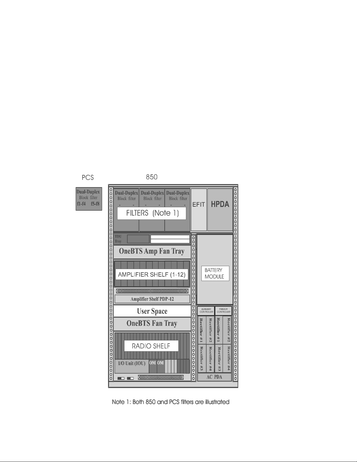
Overview of the Fl e xen t‚ Mod ular Cell 4.0B cabinet
installation
Modular Cell 4.0B cabinets
The following cabinets make up an outdoor Flexent Modular Cell 4.0B
site. These cabinets all house the CDMA radio communication
electronics, amplifiers, alarms, T1/E1 facilities interface, and filters
(except in growth cabinets), as well as the user alarm interface.
Integrated power cabinets also house a power supply, rectifiers and up
to four backup batteries (two strings).The Modular Cell 4.0B cabinet
can be shipped with components which provide from 1 to 8 cellular or
1 to 11 PCS carriers maximum, and 1 to 3 sectors, maximum. Upgrade
kits are available to add additional carriers and sectors up to the
maximums.
WITH INTEGRATED POWER
...........................................................................................................................................................................................................................................................
1-8
Lucent Technologies – Proprietary
See notice on first page
401-703-454
FOA Draft Issue 1
January, 2006
Page 54

Overview of the Flexent‚ Modular Cell 4.0B cabinet
MODULAR CELL 4.0B ONE TO TWELVE AMPLIFIER CABINET
WITH INTEGRATED POWER (3-CARRIER, 4 to 6-SECTOR)
installation
Note 1: Six PCS filters are illustrated
............................................................................................................................................................................................................................................................
401-703-454
FOA Draft Issue 1
January, 2006
Lucent Technologies – Proprietary
See notice on first page
1-9
Page 55

Overview of the Fl e xen t‚ Mod ular Cell 4.0B cabinet
CABINET WITH INTEGRA TED POWER
installation
...........................................................................................................................................................................................................................................................
1-10
Lucent Technologies – Proprietary
See notice on first page
401-703-454
FOA Draft Issue 1
January, 2006
Page 56

MODULAR CELL 4.0B CABINET WITHOUT INTEGRATED
POWER
Overview of the Flexent‚ Modular Cell 4.0B cabinet
installation
............................................................................................................................................................................................................................................................
401-703-454
FOA Draft Issue 1
January, 2006
Lucent Technologies – Proprietary
See notice on first page
1-11
Page 57

Overview of the Fl e xen t‚ Mod ular Cell 4.0B cabinet
installation
Lucent Technologies
backup power cabinets
The following backup power systems supported by Lucent are
compatible with the outdoor Flexent Modular Cell 4.0B cabinets.
First WNG24-BC battery cabinet (for use with the WNG24-K power
cabinet)
The first optional WNG24-BC battery cabinet provides additional
backup batteries (up to 10 strings - 20 batteries of type 12IR125 [or L1,
with type 1 battery shelves], or 5 strings - 30 batteries of type C-11) to
supplement the batteries in the primary cabinet or the WNG24-K
power cabinet, as applicable. The batteries are charged by the primary
cabinet or the power cabinet, as applicable. Shelf heaters are provided
to keep the batteries warm in cold weather . Temperature sensors control
the shelf heaters.
Second WNG24-BC battery cabinet (for use with the first WNG24-BC
battery cabinet only)
The second optional WNG24-BC battery cabinet is identical to the
first, but is shipped with the differing connecting hardware that is
required to attach it to the first cabinet. It also provides additional
backup batteries (up to 10 strings - 20 batteries of type 12IR125 [or L1,
with type 1 battery shelves], or 5 strings - 30 batteries of type C-11) to
supplement the batteries in the primary cabinet or the WNG24-K
power cabinet, as applicable.
First outdoor 60ECv2 battery cabinet (for use with the PowerHouse 24
cabinet only)
The first optional 60ECv2 battery cabinet provides additional backup
batteries (up to 10 strings - 20 12IR125 batteries) to supplement the
batteries in the PowerHouse 24 cabinet. The batteries are charged by
the power cabinet. Shelf heaters are provided to keep the batteries
warm in cold weather. Temperature sensors control the shelf heaters. A
"G" (Global) version of the 60ECv2 battery cabinet (60ECv2G) is also
available. This version of the battery cabinet is used for connection to
the "G" version of the PowerHouse 24 cabinet (PowerHouse 24G).
Second outdoor 60ECv2 battery cabinet (for use with the first outdoor
60ECv2 battery cabinet only)
The second optional 60ECv2 battery cabinet is identical to the first, but
is shipped with the different connecting hardware that is required to
attach it to the first cabinet. It also provides additional backup batteries
(up to 10 strings - 20 12IR125 batteries) to supplement the batteries in
the PowerHouse 24 cabinet.
...........................................................................................................................................................................................................................................................
1-12
Lucent Technologies – Proprietary
See notice on first page
401-703-454
FOA Draft Issue 1
January, 2006
Page 58
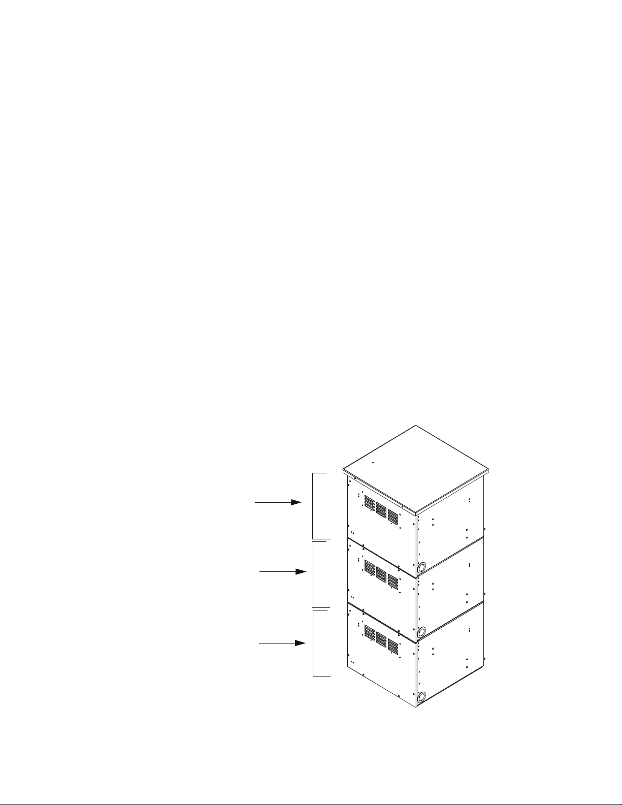
Overview of the Flexent‚ Modular Cell 4.0B cabinet
S
B
F
B
installation
EZBFo battery frames (first
and second)
This section provides a brief description of the EZBFo battery frame,
which is a backup power configuration for an outdoor Flexent Modular
Cell 4.0B primary cabinet with integrated power.
The optional EZBFo battery frame provides additional backup batteries
to supplement the batteries in an integrated power one to eight carrier
4.0B primary or dual band cabinet. The optional EZBFo battery frame
provides the initial backup batteries for an integrated power 4.0B
primary or dual band cabinet having more than 8 carriers. The batteries
are charged by the primary or dual band cabinet, as applicable.
The optional EZBFo battery frame may also be used to provide
additional backup batteries to supplement the batteries a 3GP24i power
cabinet used with non-integrated 4.0B primary or dual band cabinets.
The figure below illustrates one of two possible battery frames. Each
frame is comprised of a battery base module and two add-on modules.
The battery base module is installed first. Subsequently, add-on
modules may be separately installed. The modules below are shown
with front panels. They may also be equipped with a front door.
Note: When installing a second add-on module in zone 4, a zone 4
mounting kit is required.
econd Add-On
attery Module
irst Add-On
attery Module
Battery Base
Module
............................................................................................................................................................................................................................................................
401-703-454
FOA Draft Issue 1
January, 2006
Lucent Technologies – Proprietary
See notice on first page
1-13
Page 59

Overview of the Fl e xen t‚ Mod ular Cell 4.0B cabinet
installation
Lucent Technologies power
systems
Lucent Technologies power systems are not supported with outdoor
Flexent Modular Cell 4.0B primary and dual band two cabinet line-ups
without integrated power.
Important! If a 4.0B dual band cabinet is installed with existing
1.0, 2.0, 3.0, or 4.0 cabinets that utilize a PowerHouse24 or WNG
power cabinet, the total load for all cabinets is limited to 21 kW
for WNG-DJ, and to 17Kw for PowerHouse24, as well as WNGM and WNG-K power cabinets. The total number of carriers
possible in the 4.0B dual band cabinet will not be limited by the
use of the WHD-DJ (21 kW) power cabinet, but wil l be limit ed by
the 17 kW power cabinets (PowerHouse24, WNG-M, and WNGK power cabinets). The total number of DC terminals available in
the 17 kW power cabinets is also a limitation in some case s. In all
cases where the number of carriers is limited, use of a dual band
cabinet with Integrated Power is recommended.
...........................................................................................................................................................................................................................................................
1-14
Lucent Technologies – Proprietary
See notice on first page
401-703-454
FOA Draft Issue 1
January, 2006
Page 60
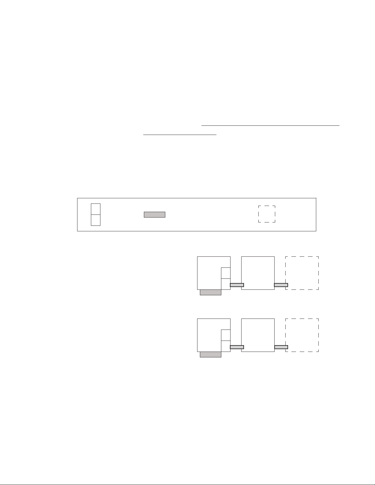
Overview of the Flexent‚ Modular Cell 4.0B cabinet
.............................................................................................................................................................................................................................................................
Outdoor Flexent Modular Cell 4.0B site descriptions (typical)
installation
Overview
4.0B primary cabinet
configuration with
integrated power
B
(BATTERY)
P
(POWER)
The following diagrams shows configuration options for a Modular
Cell 4.0B site utilizing cabinets with and without integrated po wer . The
illustrations that follow the diagrams are of typical installation sites,
which may be positioned on a concrete pad on a rooftop.
Refer to Chapter 2, Heat exchanger and solar shield configurations for
Modular Cell 4.0B cabinets on Page 2 - 69 for heat exchanger and solar
shield applications for the following configuration
FRONT HEAT EXCHANGER
OPTIONAL
*
EZBFo BATT
FRAME
CABINET 1
EZBFo BATT
FRAME
CABINET 1
1 - 3 PCS CARRIERS
(4 TO 6 SECTOR)
1 - 11 PCS CARRIERS or
1 - 8 850 CARRIERS
1-3C
4.0B
1-XC
4.0B
B
P
P
* 850 cabinets have batteries.
PCS cabinets above 8 carriers will not have batteries
because of the presence of the A6 Amplifier Shelf.
EZBFo BATT
FRAME
CABINET 2
EZBFo BATT
FRAME
CABINET 2
............................................................................................................................................................................................................................................................
401-703-454
FOA Draft Issue 1
January, 2006
Lucent Technologies – Proprietary
See notice on first page
1-15
Page 61
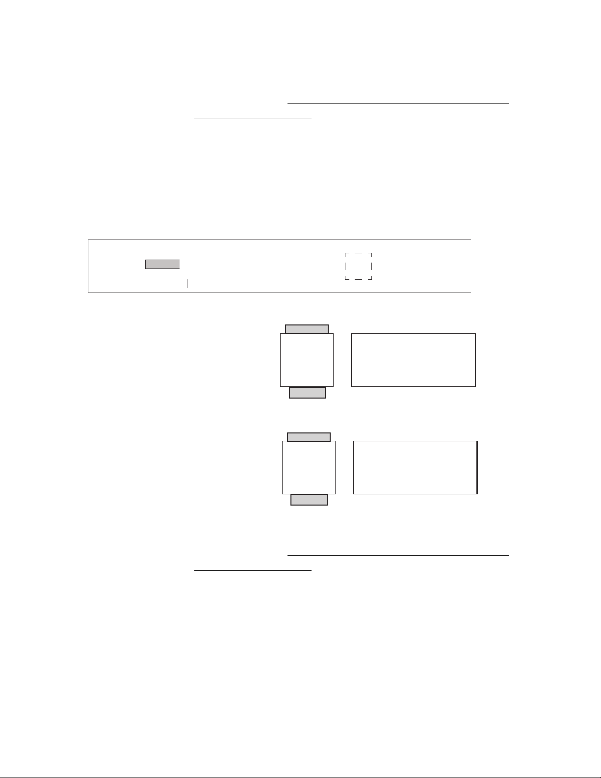
4.0B primary cabinet
configuration without
integrated power, using
customer-supplied power
and battery
Overview of the Fl e xen t‚ Mod ular Cell 4.0B cabinet
installation
Refer to Chapter 2, Heat exchanger and solar shield configurations for
Modular Cell 4.0B cabinets on Page 2 - 69 for heat exchanger and solar
shield applications for the following configuration
FRONT OR REAR
HEAT EXCHANGER,
AS APPLICABLE
OPTIONAL
1 - 3 PCS CARRIERS
(4 TO 6 SECTOR)
1 - 11 PCS CARRIERS or
1 - 8 850 CARRIERS
Refer to Chapter 2, Heat exchanger and solar shield configurations for
Modular Cell 4.0B cabinets on Page 2 - 69 for heat exchanger and solar
shield applications for the following configurations
1-3C
4.0B
1-XC
4.0B
CUSTOMERSUPPLIED POWER
AND BATTERY
CUSTOMERSUPPLIED POWER
AND BATTERY
...........................................................................................................................................................................................................................................................
1-16
Lucent Technologies – Proprietary
See notice on first page
401-703-454
FOA Draft Issue 1
January, 2006
Page 62
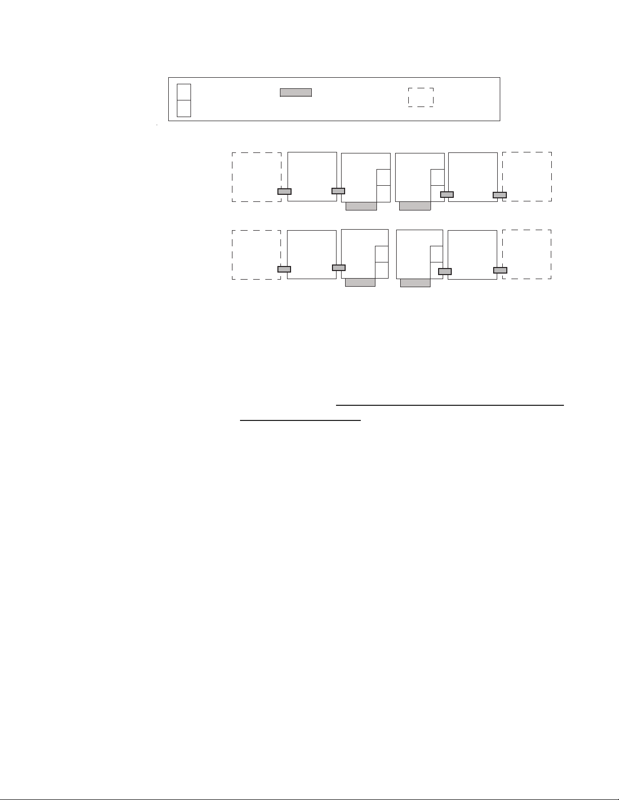
4.0B primary and dual band
cabinet configurations with
integrated power
The following diagram shows configuration options for 4.0B primary
and dual band cabinet configurations with integrated power.
Overview of the Flexent‚ Modular Cell 4.0B cabinet
installation
B
(BATTERY)
P
1-8 CELLULAR 850
CARRIERS
and 1-11 PCS
CARRIERS
(POWER)
EZBFo
BATTERY
FRAME
2
FRONT HEAT
EXCHANGER
EZBFo
BATTERY
FRAME
1
1-11C
PCS
4.0B
(Dual Band)
1-11 PCS
CARRIERS and
1-8 CELLULAR
CARRIERS
(Dual Band)
**
EZBFo
BATTERY
FRAME
2
EZBFo
BATTERY
FRAME
1
1-8C
850
4.0B
* 850 cabinets have batteries.
PCS cabinets above 8 carriers will not have batteries
because of the presence of the A6 amplifier shelf.
*
P
B
P
1-8C
850
4.0B
1-11C
PCS
4.0B
OPTIONAL
EZBFo
BATT
B
FRAME
CABINET 1
P
EZBFo
BATT
FRAME
*
CABINET 1
P
EZBFo
BATT
FRAME
CABINET 2
EZBFo
BATT
FRAME
CABINET 1
Refer to Chapter 2,
Heat exchanger and solar shield configurations for
Modular Cell 4.0B cabinets on Page 2 - 69 for heat exchanger and solar
shield applications for the following configurations
............................................................................................................................................................................................................................................................
401-703-454
FOA Draft Issue 1
January, 2006
Lucent Technologies – Proprietary
See notice on first page
1-17
Page 63
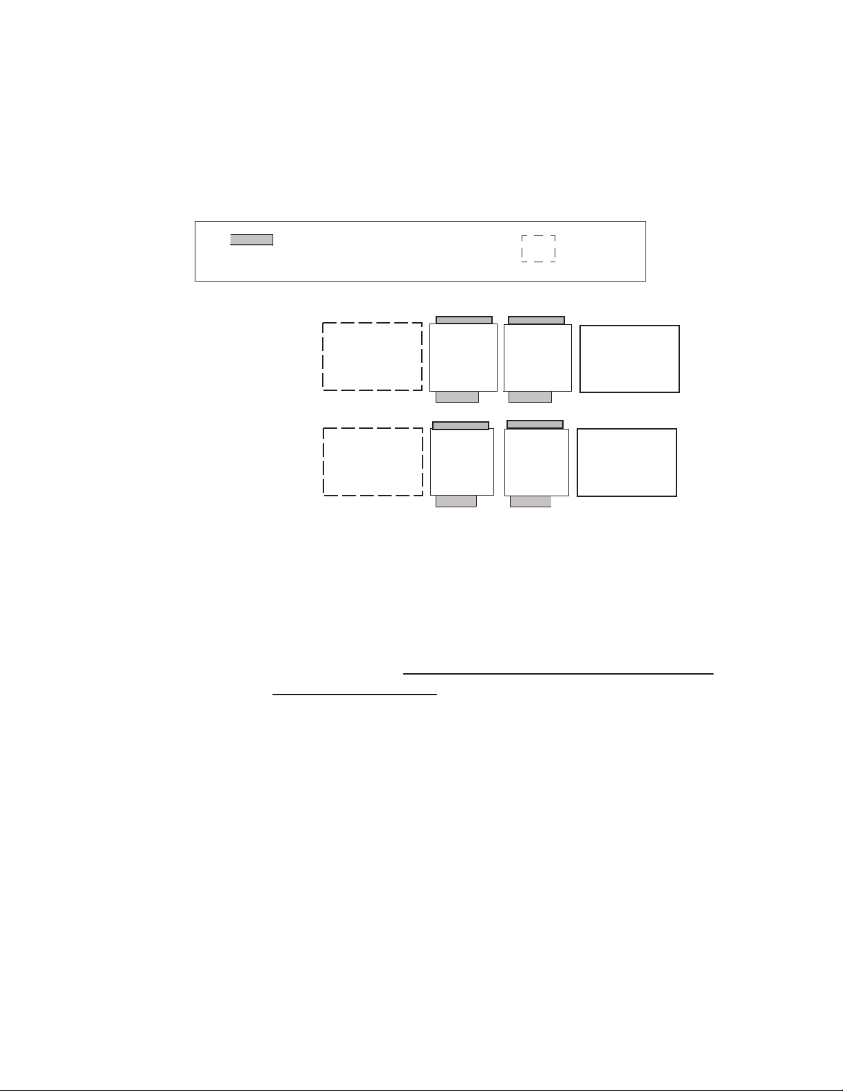
Overview of the Fl e xen t‚ Mod ular Cell 4.0B cabinet
CUSTOMERSUPPLIED
POWER AND
BATTERY **
installation
4.0B primary and dual band
cabinet configurations
without integrated power,
using customer-supplied
power and battery
1-8 CELLULAR 850
CARRIERS
and 1-11 PCS
CARRIERS
(Dual Band)
1-11 PCS
CARRIERS and
1-8 CELLULAR
CARRIERS
(Dual Band)
*
The following diagram shows configuration options for 4.0B primary
and dual band cabinet configurations without integrated power, using
customer-supplied power and battery.
FRONT OR REAR HEAT
EXCHANGER, AS APPLICABLE
CUSTOMERSUPPLIED
POWER AND
BATTERY **
CUSTOMERSUPPLIED
POWER AND
BATTERY **
1-11C
PCS
4.0B
1-8C
4.0B
1-8C
1-11C
850
850
4.0B
PCS
4.0B
OPTIONAL
CUSTOMERSUPPLIED
POWER AND
BATTERY **
CUSTOMERSUPPLIED
POWER AND
BATTERY **
* Future offering
** Customer-supplied power and battery may be
Supplied from either side, or both sides, of the line-up.
Refer to Chapter 2, Heat exchanger and solar shield configurations for
Modular Cell 4.0B cabinets on Page 2 - 69 for heat exchanger and solar
shield applications for the following configurations
...........................................................................................................................................................................................................................................................
1-18
Lucent Technologies – Proprietary
See notice on first page
401-703-454
FOA Draft Issue 1
January, 2006
Page 64

Overview of the Flexent‚ Modular Cell 4.0B cabinet
installation
4.0B dual band cabinets in
legacy line-ups with
integrated power
FRONT HEAT
EXCHANGER
5-8 850 CARRIERS
(in G-1 with 4C Primary)
1-11 PCS CARRIERS
(4.0B Dual Band)
*
7-8 850 CARRIERS
(in G-1 with 6C Primary)
1-11 PCS CARRIERS
(4.0B Dual Band)
*
The following diagram shows configuration options for 4.0B dual band
cabinets in legacy line-ups with integrated power.
**
EZBFo
BATTERY
FRAME
1and2
EZBFo
BATTERY
FRAME
1and2
1-11C
PCS
4.0B
1-11C
PCS
4.0B
B*
P
B*
P
1-4C
850
4.0
1-2C
850
4.0
B
P
B
P
1-4C
850
4.0
1-6C
850
4.0
EZBFo BATT
FRAME or
WNG BATT
B
CABINET 1
P
EZBFo BATT
FRAME or
WNG BATT
CABINET 1
P
EZBFo BATT
FRAME or
WNG BATT
CABINET 2
EZBFo BATT
FRAME or
WNG BATT
CABINET 2
8 850 CARRIERS
,G-1(3.0 Primary
AND 4.0 G-2)
1-11 PCS CARRIERS
(4.0B Dual Band)
*
EZBFo
BATTERY
FRAME
1and2
1-11C
PCS
4.0B
B*
P
1-2C
850
4.0
B
P
1-3C
850
3.0
B
P
1-3C
850
3.0
EZBFo BATT
FRAME or
WNG BATT
B
CABINET
P
1/2
* 850 cabinets have batteries; PCS cabinets above 8 carriers will not have
batteries because of the presence of the A6 amplifier shelf.
66ECv2 battery cabinets may also have been used to support the existing legacy
**
cabinets in these configurations
Refer to Chapter 2,
Modular Cell 4.0B cabinets on Page 2 - 69 for heat exchanger and solar
Heat exchanger and solar shield configurations for
shield applications for the following configurations
............................................................................................................................................................................................................................................................
401-703-454
FOA Draft Issue 1
January, 2006
Lucent Technologies – Proprietary
See notice on first page
1-19
Page 65

Overview of the Fl e xen t‚ Mod ular Cell 4.0B cabinet
installation
4.0B dual band cabinet in
legacy line-ups with
Powerhouse 24 power
cabinet
FRONT OR REAR HEAT
EXCHANGER, AS APPLICABLE
5-8 850 CARRIERS
(4.0 Primary and G-1)
1-11 PCS CARRIERS
(4.0B Dual Band)
5-8 850 CARRIERS
(4.0 Primary and G-1)
1-11 PCS CARRIERS
(4.0B Dual Band)
5-8 850 CARRIERS
()4.0 Primary and G-1
1-8 PCS CARRIERS ***
(4.0B Dual Band)
**
The following diagram shows configuration options for 4.0B dual band
cabinets in legacy line-ups with Powerhouse 24 power cabinet.
4.0B DUAL BAND
CABINET
WITHOUT
INTEGRATED
POWER
EZBFo
BATTERY
FRAME
2
EZBFo
BATTERY
FRAME
2
EZBFo
BATTERY
FRAME
1
EZBFo
BATTERY
FRAME
1
1-11C
PCS
4.0B
1-11C
PCS
4.0B
1-8 C
PCS
4.0B
B*
P
B
P
1-4C
850
4.0
1-4C
850
4.0
1-2C
850
4.0
1-4C
850
4.0
1-4C
850
B
4.0
P
1-6C
850
4.0
POWER
HOUSE
24
POWER
HOUSE
24
POWER
HOUSE
24
WNG24 OR
66ECv2
BATTERY
CABINET
1/ 2
WNG24 OR
66ECv2
BATTERY
CABINET
1/ 2
WNG24 OR
66ECv2
BATTERY
CABINET
1/ 2
8 850 CARRIERS
(1/2/3.0Primary and
G-1, 4.0 G-2)
1 - 11 PCS CARRIERS
(4.0B Dual Band)
EZBFo
BATTERY
FRAME
2
EZBFo
BATTERY
FRAME
1
1-11C
PCS
4.0B
B*
P
1-2C
850
4.0
1-3C
850
1/2/3.0
B
1/2/3.0
P
1-3C
850
B
P
POWER
HOUSE
24
WNG24 OR
66ECv2
BATTERY
CABINET
1/ 2
* 850 cabinets have batteries; PCS cabinets above 8 carriers will not have batteries because of the
presence of the A6 amplifier shelf.
** The total output of the WNG-M and WNG-K power cabinets is 17 kW, which limits the total number of
carriers in the dual band cabinet. Use of an integrated power cabinet is recommended for the line-ups
shown.
*** The number of PCS carriers limited to 8 by the number of available PH 24 DC terminals.
(See ** above for another possible limitation and recommendation.)
...........................................................................................................................................................................................................................................................
1-20
Lucent Technologies – Proprietary
See notice on first page
401-703-454
FOA Draft Issue 1
January, 2006
Page 66

Overview of the Flexent‚ Modular Cell 4.0B cabinet
installation
Refer to Chapter 2, Heat exchanger and solar shield configurations for
Modular Cell 4.0B cabinets on Page 2 - 69 for heat exchanger and solar
shield applications for the following configurations
4.0B dual band cabinet in
legacy line-ups with WNG
24 power cabinets
FRONT OR REAR HEAT
EXCHANGER, AS APPLICABLE
1-8 850 CARRIERS
(4.0 Primary and G-1)
1-11 PCS CARRIERS ***
(4.0B Dual Band)
X-8 850 CARRIERS
(4.0 Primary and G-1)
1-11 PCS CARRIERS **
(4.0B Dual Band)
4.0B DUAL BAND
CABINET
WITHOUT
INTEGRATED
POWER
EZBFo
BATTERY
FRAME
2
The following diagram shows configuration options for 4.0B dual band
cabinet in legacy line-ups with WNG 24 power cabinets.
EZBFo
BATTERY
FRAME
1
1-11C
PCS
4.0B
1-11C
PCS
4.0B
B*
P
1-X
1-2C
850
1 / 2/3/4.0
1-4Cor
1-2C
850
4.0
1-X
850
1 / 2/3/4.0
1-4Cor
1-6C
850
4.0
WNG-DJ
POWER
CABINET
WNG-
POWER
CABINET
M/K
WNG24
BATTERY
CABINET
1/ 2
WNG24
BATTERY
CABINET
1/ 2
7-8 850 CARRIERS
(1/2/3.0Primary and
G-1, 4.0 G-2)
1 - 11 PCS CARRIERS **
(4.0B Dual Band)
EZBFo
BATTERY
FRAME
2
EZBFo
BATTERY
FRAME
1
1-11C
PCS
4.0B
B*
P
1-2C
850
4.0
1-3C
850
1/2/3.0
1-3C
850
1/2/3.0
WNG-
M/K
POWER
CAB-
INET
* 850 cabinets have batteries; PCS cabinets above 8 carriers will not have batteries because of the
presence of the A6 amplifier shelf.
** The total output of the WNG-M and WNG-K power cabinets is 17 kW, which limits the total number of
carriers in the dual band cabinet. Use of an integrated power cabinet is recommended for the line-ups
shown.
*** The total output of the WNG-DJ cabinet is 21 kW, which does not limit the total number of carriers in
the dual band cabinet. Therefore, the dual band cabinet would not need integrated power in the line-up
illustrated.
............................................................................................................................................................................................................................................................
401-703-454
FOA Draft Issue 1
January, 2006
Lucent Technologies – Proprietary
See notice on first page
1-21
WNG24
BATTERY
CABINET
1/ 2
 Loading...