

Page 1

Copyright © 2008 Nokia Corporation
NWSP Wrist Unit
Assembly Instructions
Tom Ahola 2008-05-15
1 (12)
Nokia Wrist Attached Sensor Platform
Wrist Unit Assembly Instructions
Tom Ahola 2008-05-15
Copyright © 2008 Nokia Corporation
Contents
1. Electronics assembly....................................................................................................................3
1.1 Bluetooth antenna and keypad ..............................................................................................3
1.2 Charger terminals and battery................................................................................................4
1.3 Putting together the circuit boards..........................................................................................7
1.4 Adding the vibration motor.....................................................................................................9
1.5 Connecting the display.........................................................................................................10
2. Final assembly...........................................................................................................................12
Page 2
Copyright © 2008 Nokia Corporation
NWSP Wrist Unit
Assembly Instructions
Tom Ahola 2008-05-15
2 (12)
Introduction
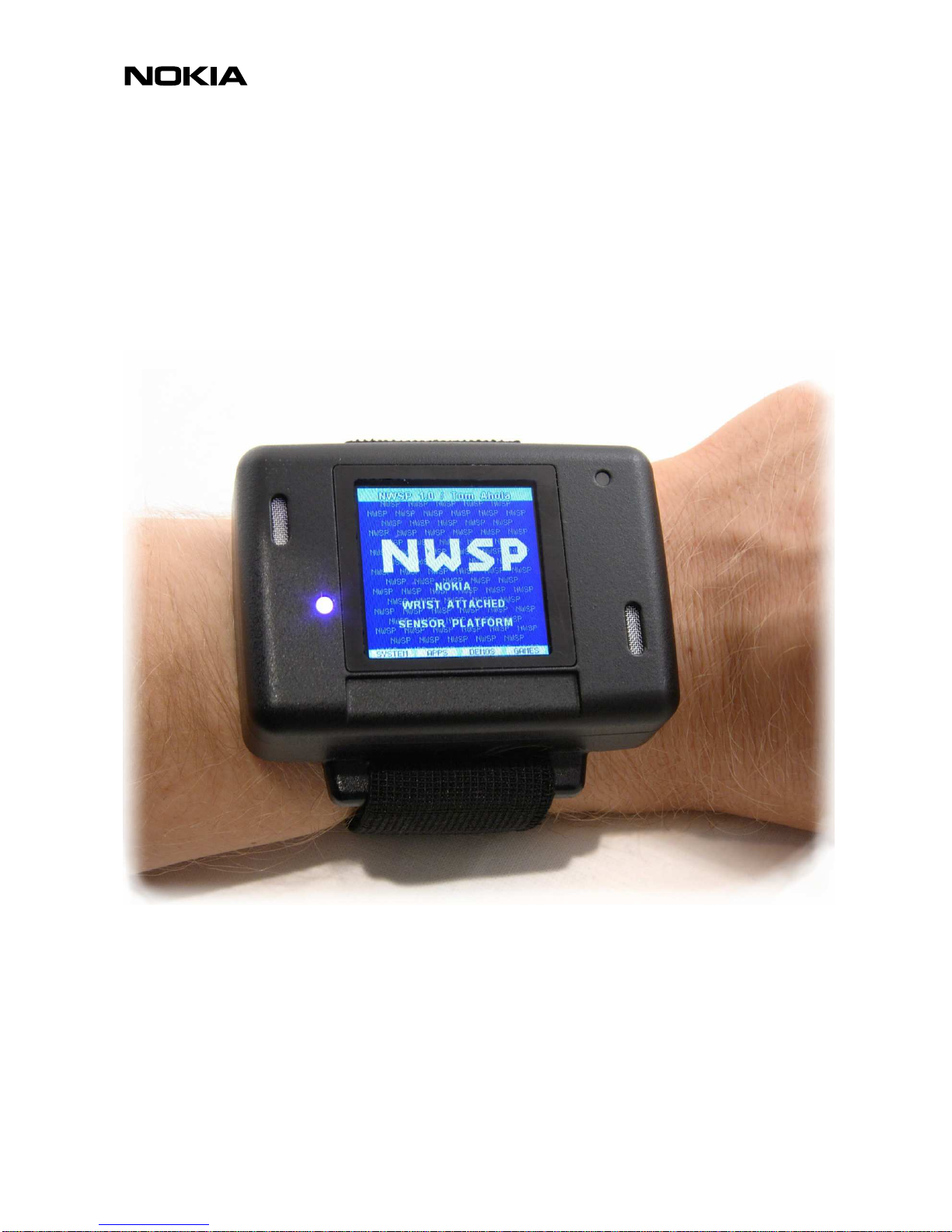
This document describes the construction of the wearable wrist unit (WU) version of the Nokia Wrist
Attached Sensor Platform (NWSP). Figure 1 shows the complete assembled unit. The two golden
charger terminals are on the right side and the opening for the power switch is on the top side (these are
not visible in the picture). There is a plastic plug that can be pushed into the power switch opening to
improve dust and water resistance. Note however that the metal gratings on the frontside are neither
dust nor water proof.
Figure 1 NWSP Development Platform Wrist Unit Assembled and Operating
Page 3
Copyright © 2008 Nokia Corporation
1. ELECTRONICS ASSEMBLY
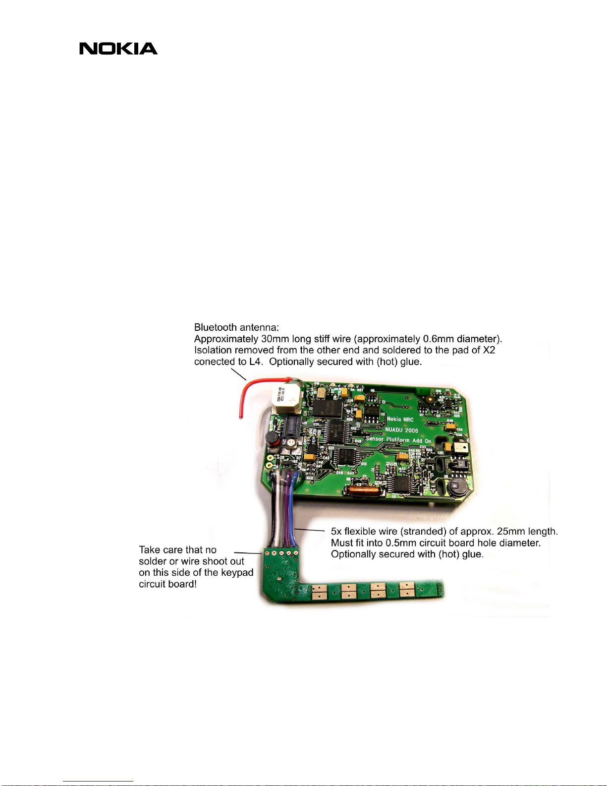
1.1 Bluetooth antenna and keypad
Start by attaching the Bluetooth antenna and touch keypad to the add-on board as shown
in Figure 2. The wires for the keypad can be a piece of ribbon cable or separate wires. For
the wrist unit the length of the cable/wires can be 20-25mm. Too long wires will be difficult
to fit into the casing. The keypad circuit board will be glued to the cover so there must not
be anything (glue, solder, wires) shooting out to the flat side of the board. The wires don’t
have to be inserted into the holes but can be soldered to the surface only. The wires
should be connected so that each one of the five pads on the keypad board are connected
to each one of the pads on the add-on board in order with the orientation of boards shown
in the figure. The wires should bend to the direction over the integrated circuit on the
keypad PWB as shown in Figure 3. Glueing of the wires is optional but recommended to
make the connections robust enough to allow opening and closing of the device several
times for programming.
NWSP Wrist Unit
Assembly Instructions
Tom Ahola 2008-05-15
3 (12)
Figure 2 Attaching the Bluetooth antenna and touch keypad to the add-on board.
Page 4

Copyright © 2008 Nokia Corporation
NWSP Wrist Unit
Assembly Instructions
Tom Ahola 2008-05-15
4 (12)
Figure 3 Capacitive touch keypad wires.
1.2 Charger terminals and battery
Attaching the charger terminal wires to the sensor platform circuit board is shown in Figure
4. Carefully observe polarity. The insulation of the negative wire should be stripped so that
it can be soldered to the two terminals of the connector as shown in the figure. Be careful
when soldering to the circuit board that there is insulation around the wire close to the
board. When the wire is bent there is risk of short circuit to the neighbouring soldering
pads on the circuit board. Use insulating (hot) glue if necessary, but make sure the wires
plus glue will not be higher than 1.5mm above the board surface because the second board
will be attached on top of this board. The wires are soldered to the charger terminals as
shown in Figure 5. Carefully observe polarity and take care not to apply too much heat so
that the plastic casing will melt. Glue can optionally be used for insulation and strength.
Page 5

Copyright © 2008 Nokia Corporation
NWSP Wrist Unit
Assembly Instructions
Tom Ahola 2008-05-15
5 (12)
Figure 4 Attaching the charger terminal wires to the sensor platform board.
Page 6

Copyright © 2008 Nokia Corporation
NWSP Wrist Unit
Assembly Instructions
Tom Ahola 2008-05-15
6 (12)
Figure 5 Soldering the wires to the charger terminals.
Attaching the battery is shown in Figure 6. IMPORTANT! First make sure that the power
switch is in OFF position. It must not be turned on before the device has been flashed with
firmware. Otherwise the I/O terminals of the FPGA are in an undefined state and this can
cause permanent damage to the device and it can become very hot. Carefully observe
battery polarity. Wires can be soldered directly to the battery terminals, taking care not to
overheat the battery. The middle contact of the battery should be left unconnected.
Page 7

Copyright © 2008 Nokia Corporation
NWSP Wrist Unit
Assembly Instructions
Tom Ahola 2008-05-15
7 (12)
Figure 6 Attaching the battery to the sensor platform circuit board.
1.3 Putting together the circuit boards
To attach the add-on board and sensor platform board together align the connectors as shown in Figure
7 and press evenly close to the connectors (not at the center of the boards). Use both hands to
simultaneously press both connectors together. Look from the side to make sure the board are
completely pressed together. The connector pins should completely go inside the platform board and
not be visible looking from the side. There should be a small snap when the connectors mate. Check
that the wires to the charger connector are neatly between the boards and are not blocking the
attachment. Fix two small pieces of double sided foam tape (thickness approximately 1mm) on the
bottom of the connectors as shown in Figure 7 for attachment of the battery.
Page 8

Copyright © 2008 Nokia Corporation
NWSP Wrist Unit
Assembly Instructions
Tom Ahola 2008-05-15
8 (12)
Figure 7 Attaching the add-on board to the sensor platform board.
Figure 8 shows the battery taped to the bottom of the circuit board assembly. It is important that the end
of the battery with the wires is not protruding (including wires and glue) outside the edge of the circuit
boards. In the figure the battery is slightly too much to the left leaving the glued wires outside the board
making the assembly too wide to fit into the mechanics. The JTAG connector (J6) on the right should
not be blocked by the battery either.
Page 9

Copyright © 2008 Nokia Corporation
NWSP Wrist Unit
Assembly Instructions
Tom Ahola 2008-05-15
9 (12)
Figure 8 Attaching the battery to the circuit board assembly with double sided tape.
1.4 Adding the vibration motor
Figure 9 shows the vibration motor (vibra) added to the electronics assembly. The vibra is optional and
the model might vary. This model is a Jahwa JHV-10, which is a coin type that runs off the 3.7V battery
voltage. Note the short blue and red wires that are soldered to the circuit board. In the figure the battery
has a white plastic holder. If these holders are not used the vibra must be taped or glued directly to the
battery, taking care that the battery terminals are not short circuited, even if the vibra becomes loose.
There is a cavity for the vibra in the bottom part of the casing, so stick the vibra to the battery in a place
so that it is aligned with this cavity and so that it does not extrude below the battery.
Page 10

Copyright © 2008 Nokia Corporation
NWSP Wrist Unit
Assembly Instructions
Tom Ahola 2008-05-15
10 (12)
Figure 9 Adding the vibration motor.
1.5 Connecting the display
On top of the electronics assembly in locations shown in Figure 10 (ignore everything else in this
picture, as it is showing the development unit.), where there are no components on the circuit board
supports for the LCD display should be placed. These supports should be approximately 3mm high and
flexible. In this prototype three layers of 1mm thick double sided foam tape has been used.
Page 11

Copyright © 2008 Nokia Corporation
NWSP Wrist Unit
Assembly Instructions
Tom Ahola 2008-05-15
11 (12)
Figure 10 Double sided foam tape supports for LCD display added to the electronics assembly. (Ignore
everything else in this picture, as it is showing the development unit.)
The LCD has been attched to the platform in Figure 9. First snap the LCD connector in place and then
lower the LCD to the double sided tape supports. Because it is not possible to adjust the position of the
display after it has been taped, the connector must be connected before the display touches the tape.
Page 12

Copyright © 2008 Nokia Corporation
NWSP Wrist Unit
Assembly Instructions
Tom Ahola 2008-05-15
12 (12)
2. FINAL ASSEMBLY
For the final assembly first glue the keypad circuit board to the recess on the inside of the cover as
shown in Figure 3. Also thin double sided tape could be used. Also stick the metal gratings to the cover
inside to cover the oblong holes if this has not been done already. Then carefully align the display to the
four guides beside the window in the cover. First make sure the window and display is clean and the
protective plastic has been removed from the display. Gently press the assembly into place until the
display is against the cover. Depending on battery thickness some filler is needed to create some slight
compression when the case is closed. For a typical battery of 4.6mm thickness approximately 0.8 mm
filler is needed. In Figure 5 the filler is a sheet of cardboard glued to the bottom of the casing. The filler
can also be rubber tape or similar. The pressure should be gentle on the diplay so it does not bend or
break, but firm enough so that the connectors between the circuit boards stays connected and the
display and rest of the electronics does not move around inside the case. The foam tape between the
display and circuit board is flexible enough to make an ideal pressure. Route the charging terminal wires
around the battery and check that no wires are in between when the case is closed by the four screws.
This can be tricky with the long charging terminal wires. Use tape or glue to fix the wires to make this
easier, but make sure the device can be easily opened for programming later. The final device should
look something like Figure 1.
 Loading...