

Page 1

PAMS Technical Documentation
NSW-6 Series Transceivers
Tuning, Flashing and
NAM programming
instructions
Issue 1 12/99 Nokia Mobile Phones Ltd.
Page 2
NSW-6
Tuning, Flashing and NAM programming instructions
AMENDMENT RECORD SHEET
PAMS Technical Documentation
Amendment
Number
Date Inserted By Comments
12/99 OJuntune Original
Page 2
Nokia Mobile Phones Ltd.
Issue 1 12/99
Page 3

PAMS Technical Documentation
Tuning, Flashing and NAM programming instructions
CONTENTS
Tuning Instructions 4. . . . . . . . . . . . . . . . . . . . . . . . . . . . . . . . . . . . . .
General 4. . . . . . . . . . . . . . . . . . . . . . . . . . . . . . . . . . . . . . . . . . . . .
Required Equipment 5. . . . . . . . . . . . . . . . . . . . . . . . . . . . . . . . . .
Equipment Setup 5. . . . . . . . . . . . . . . . . . . . . . . . . . . . . . . . . . . . .
Central Service Concept for NSW–6 6. . . . . . . . . . . . . . . . . .
Point of Sale Flash Concept for NSW–6 7. . . . . . . . . . . . . . .
Tuning with covers off using Module Jig JBS-25 8. . . . . . . .
Tuning Steps 9. . . . . . . . . . . . . . . . . . . . . . . . . . . . . . . . . . . . . . . . .
1. AFC Tuning 9. . . . . . . . . . . . . . . . . . . . . . . . . . . . . . . . . . . . .
2. VCTCXO Tuning 9. . . . . . . . . . . . . . . . . . . . . . . . . . . . . . . . .
3. I/Q Modulator Amplitude Balance and
Phase Shift Tuning 10. . . . . . . . . . . . . . . . . . . . . . . . . . . . . . . .
4. Tuning of Transmitter Power Levels 10. . . . . . . . . . . . . . . .
800MHz Analog TX output power 11. . . . . . . . . . . . . . . . . . . .
800MHz Digital TX output power 11. . . . . . . . . . . . . . . . . . . . .
TDMA1900 TX output power 12. . . . . . . . . . . . . . . . . . . . . . . .
5. RSSI Digital Receiver (AGC) 12. . . . . . . . . . . . . . . . . . . . . .
6. RSSI Analog Receiver 13. . . . . . . . . . . . . . . . . . . . . . . . . . . .
7. RX Audio 13. . . . . . . . . . . . . . . . . . . . . . . . . . . . . . . . . . . . . . .
8. TX Audio 13. . . . . . . . . . . . . . . . . . . . . . . . . . . . . . . . . . . . . . .
9. TX Audio 13. . . . . . . . . . . . . . . . . . . . . . . . . . . . . . . . . . . . . . .
NAM programming instructions 14. . . . . . . . . . . . . . . . . . . . . . . . .
Menu driven easy NAM programming 14. . . . . . . . . . . . . . . . . . .
Complete NAM Programming Instructions 15. . . . . . . . . . . . . . .
Access NAM Programming Mode: 15. . . . . . . . . . . . . . . . . . . .
MAIN MENU Selection 15. . . . . . . . . . . . . . . . . . . . . . . . . . . . . .
Programming NAMs 1 through 3 15. . . . . . . . . . . . . . . . . . . . .
Programming the Security Code: 16. . . . . . . . . . . . . . . . . . .
Programming Emergency numbers: 16. . . . . . . . . . . . . . . .
Serial Number (ESN): 16. . . . . . . . . . . . . . . . . . . . . . . . . . . .
Programmed: (Date the phone is first programmed) 16. .
Exiting NAM Programming: 16. . . . . . . . . . . . . . . . . . . . . . .
Field test: 17. . . . . . . . . . . . . . . . . . . . . . . . . . . . . . . . . . . . . . .
Programming PSIDS and RSIDS: 17. . . . . . . . . . . . . . . . . . . .
NSW-6
Page No
Warranty transfer 19. . . . . . . . . . . . . . . . . . . . . . . . . . . . . . . . . . . . . . .
Warranty Transfer service concept 19. . . . . . . . . . . . . . . . . . .
Issue 1 12/99
Nokia Mobile Phones Ltd.
Page 3
Page 4

NSW-6
Tuning, Flashing and NAM programming instructions
Tuning Instructions
General
All tuning operations of the NSW–6 are carried out using the service software. The service software turns the phone into the locals mode, in which
the phone can be outwardly controlled via the MBUS interface.
Tuning is based on the software communicating with the D/A and A/D
converters of the phone. In some instances the phone processor will also
calculate the required correction parameter.
The tuning values of the phone reside on the EEPROM. The contents of
the EEPROM can be read by the service software and saved as a file.
This is advisable when there is need to retain that information, e.g. in
view of replacement of the circuit. The program also enables writing the
default parameters on the EEPROM, in which case all tuning steps should
be carried out.
PAMS Technical Documentation
During tuning, proceed as follows:
– Take care not to damage sensitive measuring instruments with exces-
sive RF power.
– Carry out all tuning steps in the shortest possible time to avoid exces-
sive heating of RF units.
– Perform all tuning steps in the order presented.
– Never try to mask a fault by tuning it out!
Page 4
Nokia Mobile Phones Ltd.
Issue 1 12/99
Page 5

PAMS Technical Documentation
Required Equipment
– PC/AT computer with service software; see separate section for
instructions on installation and use.
– Service accessories; see equipment setup pictures.
– Multimeter or DVM.
– Measuring equipment as follows:
– RF generator
– pulse power meter
– spectrum analyzer
– attenuator and branching unit
Equipment Setup
NSW-6
Tuning, Flashing and NAM programming instructions
Caution: Make sure that you have switched off the PC and the printer
before making connections !
Caution: Do not connect the PKD–1 key to the serial port. You may
damage your PKD–1 !
Attach the protection key PKD–1 to parallel port one (25–pin female
D–connector) of the PC. When connecting the PKD–1 to the parallel port
be sure that you insert the PC end of the PKD–1 to the PC (male side). If
you use a printer on parallel port one, place the PKD–1 between the PC
and your printer cable.
Next connect the M2BUS service cable, DAU–9S, to the serial port
(RS–232) of the computer. Attach one end of the service cable to the PC
serial port and the other end to the service box, JBU–8 or Flash Adapter
FLA-9.
When the phone covers are removed the jig JBS-25 must be used.
For audio measurements the audio box JBA-6 is used.
Warning: Do not use JBU–8 for tuning!
Issue 1 12/99
Nokia Mobile Phones Ltd.
Page 5
Page 6
NSW-6
Tuning, Flashing and NAM programming instructions
Central Service Concept for NSW–6
15.
4.
14.
PAMS Technical Documentation
12.
13.
7.
6.
5.
Item: Service accessory: Type Product code:
1 Flash Loading Adapter FLA–5 0770085
2 Flash Security Box TDF–4 0770106
3 Flash Prommer FPS–4 0085095
4 Service Junction Box JBU–8 0770188
5 DC Cable PCS–1 0730012
6 Service Cable XMS–3 0730174
7 DC Cable PCC–1B 0730053
8 Printer Cable (Included in FPS–4 sales pack) 0730029
9 D15 – D15 Cable AXS–5 0730091
10 D9 – D9 Cable AXS–4 0730090
11 D9 – D9 Cable AXS–4 0730090
12 Software protection key PKD–1 0750018
13 Service SW diskette 3.5” for NSW–6 0774099
14 Travel Charger ACH–6U (USA/Japan) 0270382
15 AC Charger ACL–3E 0680015
1.
11.
2.
3.
(Included in FLA–5 sales pack)
(Included in FPS–4 sales pack)
Service SW diskette 3.5” for WinTesla 0774046
(Included in FPS–4 sales pack)
10.
9.
8.
Page 6
Nokia Mobile Phones Ltd.
Issue 1 12/99
Page 7

PAMS Technical Documentation
Tuning, Flashing and NAM programming instructions
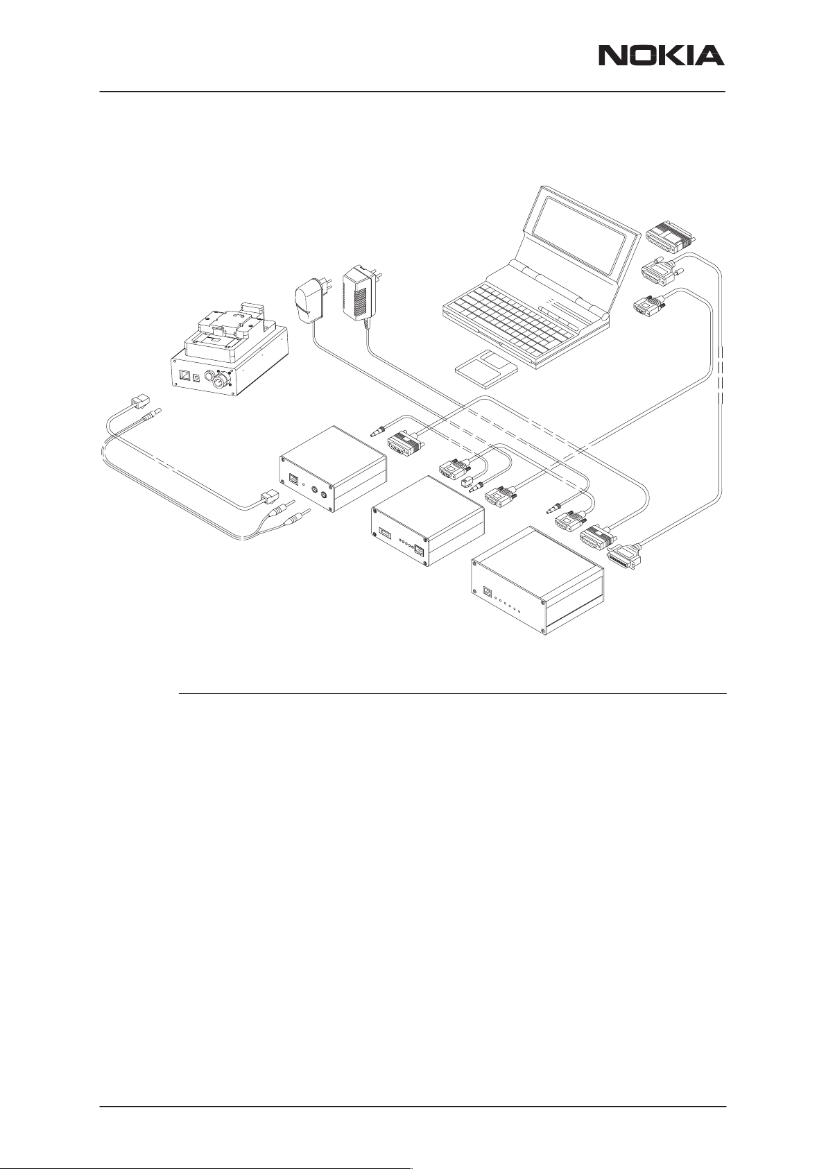
Point of Sale Flash Concept for NSW–6
With this equipment setup the user can flash a new software in the
phone.
NSW-6
2.
Laptop PC
4.
3.
6.,7.,8.
1.
5.
Item: Service accessory: Type Product code:
1 Flash Battery Adapter FLA-9 0770184
2 POS Flash Adapter FLS-2D 0750130
3 Modular Cable XMS–3 0730174
4 D9–D9 Cable AXS–4U 0730090
5 Travel Charger ACP–8U 0271610
6 Service SW diskette 3.5” for 16bit Dongle Drivers 0770177
(Windows 3.1x)
Service SW diskette 3.5” for 32bit Dongle Drivers 0770176
Alt. (Windows 95/98/NT)
7 Service SW diskette 3.5” for FLE–5 drivers 0774046
8 Service SW diskette 3.5” for FLS–1 Remote Update
Application Installation Pack: 0774123
FLS-2D Sales Pack, Installation and User Guide 0275405
FLS-2D Registration Request Form 0275404
Service SW diskette 3.5” for NSW-6 0774099
Issue 1 12/99
Nokia Mobile Phones Ltd.
Page 7
Page 8

NSW-6
Tuning, Flashing and NAM programming instructions
PAMS Technical Documentation
Tuning with covers off using Module Jig JBS-25
2.
5.
4.
3.
1.
Item: Service accessory: Type Product code:
1 Module Jig JBS–25 0770185
2 Travel Charger ACP–8U 0271610
3 Service MBUS Cable DAU–9S 0730108
4 Software Protection Key PKD–1 0750018
5 Service SW diskette 3.5” for NSW–6 0774099
Page 8
Nokia Mobile Phones Ltd.
Issue 1 12/99
Page 9

PAMS Technical Documentation
Tuning Steps
Note About Supply voltage.
The Service battery (Flash adapter) FLA–9 used for NSW–6 differs from
the standard DCT3–Service battery. The max. supply voltage is 16 V.
1. AFC Tuning
This tuning adjusts the frequency of the reference oscillator so that the
frequency criteria of the network will be met.
This adjustment loads the analog center frequency offset DAC value into
the EEPROM. When doing this, a spectrum analyzer must be used.
NSW-6
Tuning, Flashing and NAM programming instructions
Note:
current. A prolonged tuning session may damage the phone or service battery. The
service battery will be heated.
Do not leave a tuning session on.
The spectrum analyzer settings are shown in the AFC tuning window.
– – Set the power supply voltage. See instructions above.
– – Connect the spectrum analyzer to the antenna adapter or to the
diagnostic jig.
– – Check that the spectrum analyzer center frequency is correct.
– – Tune the center frequency 832.500 MHz +/– 200 Hz.
– – Once the center frequency is correct, press OK button.
The analog transmitting takes maximum
2. VCTCXO Tuning
This tuning is to check that the radio unit has correct adjustment to meet
the network criteria for frequency stability.
This adjustment loads the VCTCXO offset DAC value into the EEPROM.
RF signal generator must be used in tuning.
– –Set the power supply voltage. See instructions above.
– –Connect the RF signal generator to the antenna adapter or to the
– –Once the RF signal generator frequency is correct, press Meas but-
– –Set the correct RF level to the signal generator.
– –Remember to note the attenuation at RF signal level !
– –Once the frequency and RF level are correct, press OK button.
Issue 1 12/99
diagnostic jig JBS–25.
ton.
Nokia Mobile Phones Ltd.
Page 9
Page 10

NSW-6
Tuning, Flashing and NAM programming instructions
PAMS Technical Documentation
3. I/Q Modulator Amplitude Balance and Phase Shift Tuning
This tuning is to adjust the DC–offset and phase offset of the I and Q–
modulators so that the system requirements for modulation accuracy will
be met.
– –Select Tuning ––> TX I / Q
– –Connect the spectrum analyzer to the antenna adapter or diagnostic
jig.
– –Use the following settings for spectrum analyzer in tuning:
– Set spectrum analyzer center frequency to 830.700 MHz.
– Set span 80 kHz
– Set Ref LVL 20 dB
– Set RBW and VBW 1 kHz
– Set sweep time 0.3 s
– –Use ”TX I DC Offset” and ”TX I DC Offset” option to adjust CFR – 7.1
kHz to minimum.
– The amplitude difference between CFR and CFR – 7.1 kHz must be >
40 dB.
– –Use ”Phase Offset ” option to adjust CFR – 14.2 kHz to minimum
– The amplitude difference between CFR and CFR – 7.1 kHz must be >
40 dB.
– –Once the TX I, TX Q and phase shift are aligned, press SAVE button.
4. Tuning of Transmitter Power Levels
– This tuning is to adjust the output power level values of the radio unit
according to the system specification.
– This adjustment loads the power levels of the phone transmitter into
the EEPROM. When doing this, a pulse power meter or spectrum
analyzer must be used.
– Tuning targets are listed next page.
– –Set power supply voltage. See Note above.
– –Connect the pulse power meter or spectrum analyzer. Use attenua-
tor, if needed.
– – Settings for spectrum analyzer in power level tuning:
– Set span 0 Hz
Page 10
– Set Ref LVL 30 dB
– Set Ref LVL offset and ––> Attenuation to Antenna Pad
– Set RBW and VBW 300 kHz
– Set sweep time 50 ms
– Set TRIG: SWEEP CONT, VIDEO –10 dBm
– Set marker at middle of slot.
– Check that spectrum analyzer frequency is correct
Nokia Mobile Phones Ltd.
Issue 1 12/99
Page 11

PAMS Technical Documentation
– –Settings for pulse power meter:
– Do calibration if needed.
– Set correct frequency
– Set Ref LVL offset ––> Attenuation to Antenna Pad
– Set correct duty cycle, 33,3 % in digital mode and 100 % at
analog mode.
– –Select Tuning –> Using WinTesla Select Tuning –> TX power –>
LowBand/HighBand –>EEPROM values
– –All four tuning channels have to be tuned. Repeat tuning for A, B, C
and D tuning channel. Tuning channel change reads old tuning values
from phone’s EEPROM.
– –Adjust power level by clicking the + and – buttons, power level
change is done by keyboard keys ↑ and ↓ .
– –Tune the power levels, which are shown by ”# for calculate”
NSW-6
Tuning, Flashing and NAM programming instructions
– –Press Calculate button to calculate other power levels.
– –Check tuning, Do fine tuning if needed.
– –Once all TX tuning channels are correct, press SAVE button
– –Tuning is done, if both Analog mode and 800 MHz and 1900 MHz
digital mode are tuned
There are different results when measuring TX power from the Test Pad
of panel or the Antenna Pad, It must be ensured that the measurements
from the Antenna Pad give correct results.
.
800MHz Analog TX output power
Power Level RF Power at An-
tenna Pad
2 26.0 dBm +/–0.1 dB +0.5…– 1.0 dB
800MHz Digital TX output power
Tuning Target
Tolerance
.
Testing Limits
26.5 – 25.0 dBm
Power Level RF Power at ext.
Antenna Pad
2 26.8 dBm +/–0.1 dB +0.5…– 1.0 dB
3 23.5 dBm +/–1 dB +/– 2.0 dB
4 20.0 dBm +/–1 dB +/– 2.0 dB
5 16.0 dBm +/–1 dB +/– 2.0 dB
6 12.0 dBm +/–1 dB +/– 2.0 dB
Issue 1 12/99
Nokia Mobile Phones Ltd.
Tuning Target
Tolerance
Testing Limits
27.3 – 25.8 dBm
Page 11
Page 12

NSW-6
Tuning, Flashing and NAM programming instructions
PAMS Technical Documentation
Power Level
7 8.0 dBm +/–1 dB +/– 2.0 dB
8 4.0 dBm +/–1 dB +/– 2.0 dB
9 0.0 dBm +/–1 dB +/– 2.0 dB
10 –4.0 dBm +/–1 dB +/– 2.0 dB
Check that power level PL2 TXC DAC value is in the allowed range
+50...300.
RF Power at ext.
Antenna Pad
TDMA1900 TX output power
Power Level RF Power at ext.
Antenna Pad
2 25.9 dBm +/–0.1 dB +0.5…– 1.0 dB
3 23.0 dBm +/–1 dB +/– 2.0 dB
4 20.0 dBm +/–1 dB +/– 2.0 dB
5 16.0 dBm +/–1 dB +/– 2.0 dB
Tolerance
Tuning Target
Tolerance
Testing LimitsTuning Target
Testing Limits
26.4 – 24.9 dBm
6 12.0 dBm +/–1 dB +/– 2.0 dB
7 8.0 dBm +/–1 dB +/– 2.0 dB
8 4.0 dBm +/–1 dB +/– 2.0 dB
9 –0.0 dBm +/–1 dB +/– 2.0 dB
10 –4.0 dBm +/–1 dB +/– 2.0 dB
Check that power level PL2 TXC DAC value is in the allowed range
+0...+250.
5. RSSI Digital Receiver (AGC)
This tuning is to measure the small signal gain of the radio unit to meet
the system requirements for RSSI reporting.
– –Select tuning ––>RSSI Digital (AGC) ––> Low Band / High Band.
– –Set the power supply voltage. See instructions above.
– –Connect the RF signal generator to the antenna adapter or service
jig.
– –Press Meas ––> Dialog window shows the correct frequency and sig-
nal level.
Page 12
– Levels for Low Band are –98, –88, –78, –68 and –58 dBm
and
– Levels for Upper Band are –95, –85, –75, –65 and –55 dBm
– –Note, Cable loss.
Nokia Mobile Phones Ltd.
Issue 1 12/99
Page 13

PAMS Technical Documentation
– –Repeat measurement with all signal levels.
– – Once tuning is correct, press OK button.
6. RSSI Analog Receiver
This measurement is for RSSI in analog mode, 800 MHz range.
– –Select Tuning ––> RSSI Analog.
– –Set power supply voltage. See instructions above.
– –Connect the RF signal generator to antenna adapter or service jig.
– –Press Meas ––> Dialog window shows the correct frequency and sig-
nal level.
– –Note, Cable loss.
– –Repeat the measurement with all signal levels.
– –Once tuning is correct, press OK button.
NSW-6
Tuning, Flashing and NAM programming instructions
7. RX Audio
This measurement is for Audio output calibration of DAMPS mode. When
doing this a signal generator must be used.
– –Select tuning ––> RX Audio.
– –Connect the XMIC line to signal generator.
– –Tune the signal to the correct level.
– –Once the tuning is correct, press OK button.
8. TX Audio
This measurement is for Audio output calibration for DAMPS mode.
When doing this the signal generator must be used.
– –Select tuning ––> RX Audio.
– –Connect the XMIC line to signal generator.
– –Tune the signal to the correct level.
– –Once tuning is correct, press OK button.
9. TX Audio
– –Connect the phone to the service box JBU–8 and the DC cable
– –Set the supply voltage to 10 V
– –Select Tuning ––> Charging
– –Run calibrations by pressing <Meas> button.
– –Set supply voltage back to 8 V.
Issue 1 12/99
(SCB–3) between the phone and service box.
Nokia Mobile Phones Ltd.
Page 13
Page 14

NSW-6
Tuning, Flashing and NAM programming instructions
PAMS Technical Documentation
Nokia 8860 cellular telephone NAM programming instructions
All Nokia 8860 cellular telephones are capable of supporting both Random and Default authentication methods. This programming guide describes the programming of generic 8860 handsets. The programmer
must decide which A–Key type is desired for use.
There are two methods to program the NAM described below.
If a RANDOM A–Key is desired for use, use the Easy NAM 1 program-
ming sequence.
If a DEFAULT A–Key is required, then use the Easy NAM 2 sequence.
Use the appropriate NAM if the Long NAM programming method is used.
Use the CLEAR key to erase any mistakes.
Menu driven easy NAM programming
D
#639?#
*
Clear
Save
Enter Cellular
number:
OK
Enter Code
OK
Activation
OK
1. Turn on the phone and enter the Programming Access Code
*#6391# For NAM1 with a Random A–Key Value
*#6392# For NAM2 with a Default A–Key Value
*#6393# For NAM3 with a Default A–Key Value
2. Enter the 10 digit Area Code and Phone Number
Press the TALK key (or the ”OK” softkey in the display)
3. Enter the System ID Code (SID) supplied by the cellular service provider (1 –5 digit SID) and press the TALK key (or ”OK”
softkey in the display)
- Optional settings are Language and Lock Code (see below)
•
4. Short NAM Programming is completed
- The phone automatically powers off and then back on
Page 14
NOTE:
Change the Lock code by adding a pound sign (£) and the new lock code
after the SID. (Example: 175£7788; Lock code = 7788).
Change the Language by adding a pound sign and new language code after
the code (Example: 175£0; Language = English).
Language Code: 0 (default) = English, 1 = French, 2 = Spanish, 3 = Portuguese.
Nokia Mobile Phones Ltd.
Issue 1 12/99
Page 15

NSW-6
БББББ
Á
Á
Á
Á
Á
Á
Á
Á
Á
Á
Á
Á
Á
Á
Á
Á
Á
Á
Á
PAMS Technical Documentation
Tuning, Flashing and NAM programming instructions
Change the Lock Code and Language code by separating each set of numbers by a pound sign (Example: 175£7788£2; Where the SID = 00175, Lock
code = 7788, Language = Spanish).
Complete NAM Programming InstructionsnENNDPORTABLES
Access NAM Programming Mode:
1. Turn the phone on.
2. Enter the NAM access code.
Factory default is: * 3 0 0 1 # 1 2 3 4 5 #
3. If the screen to the left appears, the access code was entered correctly.
D
1
NAM 1
NAM 2
NAM 3
Select
If after several attempts you can not access NAM programming, it is possible that the NAM 2 access code has been
changed, or the phone is in need of service.
MAIN MENU Selection
4. Press the [Scroll–Key] up or down until the indicator highlights the desired
menu option. Select from the following:
NAM 1
SW version
NAM 2
Serial No.
5.Press the [Select] softkey to access the Sub–Menu from and of the above
Main Menu selections.
Programming NAMs 1 through 3
6. If the value is incorrect, press the [Select] softkey and use the keypad to
enter new information.
Home
ÁÁÁ
system ID
ÁÁÁ
NAM Status
Home SOC
ББББББ
(when unlocked)
ББББББ
Change Defaults (sub–menu from above)
Access method
NAM 3
Programmed
Own
ÁÁÁ
number
ÁÁÁ
Security
Field Test
Alpha tag
ÁÁÁ
ÁÁÁ
Local option
Emergency
PSID/RSID
ÁÁÁÁ
lists
ÁÁÁÁ
Primary paging chan-
Change
ÁÁÁÁ
defaults
ÁÁÁÁ
(Enable/Disable)
ББББББББ
Secondary paging ch
ББББББББ
Dedicated B cch num-
ББББББББ
ber
A–key code
Issue 1 12/99
ББББББ
Dedicated A cch
ББББББ
ББББББ
Dedicated A cch
ББББББ
Overload class
ББББББ
Public systems
ББББББ
Private systems
Nokia Mobile Phones Ltd.
number
Group ID
ББББББББ
nel
Dedicated B cch
ББББББББ
SID alpha tag control
ББББББББ
Residential systems
Page 15
Page 16

NSW-6
Tuning, Flashing and NAM programming instructions
7. Use the [OK] softkey to store the new information that has been entered.
8. Repeat steps 6 and 7 for the remaining NAM parameter options to be
viewed and/or changed.
Programming the Security Code:
9. From the Main Menu, use the scroll keys to select the “Security” Sub–
Menu, press [Select] and the current 5–digit security code will appear in the
display. Default is 12345
10. If you wish to change the Security Code at this time, use the numeric
keys to enter the new value.
11. Press the softkey [OK] to store changes.
Programming Emergency numbers:
12. From the Main Menu use the scroll key to select the ”Emergency” Sub–
Menu, press the [Select] softkey to access the emergency numbers.
PAMS Technical Documentation
Emergency number 1 (911)
Emergency number 2 (*911)
Emergency number 3 (None)
13. If you wish to change the displayed value, use the scroll key to select
the emergency number you wish to change and press [Select]. Then use the
numeric keys to enter the new values
14. To save the value, press the softkey [OK].
15. Press [Back] to exit the menu.
Serial Number (ESN):
17. From the Main Menu, use the scroll key to display the “Serial No.” or ESN
of the phone.
18. Press [Back] to exit the menu.
Programmed: (Date the phone is first programmed)
19. From the Main Menu, use the key to display the “Programmed” menu.
20. Press [Select] and enter a four digit number that corresponds to the
month and year the phone is sold. Example (mmyy)
0199 = January 1999, 0401 = April 2001.
NOTE: This menu location can be programmed only one time. Once
the date has been entered it can not be changed. Any attempt to enter the
menu once it has been programmed will receive a short beep and the message “Date already saved”.
Exiting NAM Programming:
21. To exit the NAM programming mode, turn the phone off and leave it off
for five seconds.
Page 16
Nokia Mobile Phones Ltd.
Issue 1 12/99
Page 17

PAMS Technical Documentation
Field test:
The Field Test Display Mode is used to investigate how the phone and the
cellular network are interfacing together.
The Field Test Display Mode reports valuable information about the signal
strength, battery charging status, cellular state and encryption status.
The information is organized to display information relating to Analog Control
Channels, Digital Control Channels, Analog Voice Channels, and Digital
V oice channels. All the information provided in this display is in accordance
with IS–136.
To activate the Field Test Display Mode you must be in NAM programming.
Instructions for entering NAM programming are on the previous pages.
From the Main Menu use the scroll key to display the ”Field test” menu and
press the [Select] softkey.
Use the Scroll key to select “Enable” and press the [OK] softkey.
NSW-6
Tuning, Flashing and NAM programming instructions
Turn the 8860 off then back on. The FIELD TEST display will begin automatically after wake–up as long as the user does not enter any characters into
the display.
Scroll through the 7 different displays using the scroll key. Note that the
automatic scroll feature for the Short Code Memory is disabled.
To disable the FIELD TEST mode. Return to NAM programming and disable the function under the FIELD TEST menu. Or, select MENU 10 and
enter [00] in the field and press [OK].
Programming PSIDS and RSIDS:
The Nokia 8860 provides the option to program Private (PSIDs) and Residential (RSIDs) System ID’s as prescribed by IS–136. The PSID / RSID
list is programmed to support system selection / re–selection processes,
and SID display functions.
The Nokia 8860 product will support up to 5 different Private or Residential Systems in NAM 1. Using the NAM programming menu to program
the PSID / RSID is just one of several ways that this information can be
programmed. The phone also supports automatic programming of the
PSID / RSID values via registration accept message from a Public & Private system, manually prompting with System Scan sub–menu option
“New Search”, or via Over the Air Programming. Follow these instructions to program the PSID / RSID lists.
1. Enter the NAM programming menu and select NAM 1 (or the desired
NAM). (Note: PSID / RSID is currently only available in the NAM 1 location.
PSID / RSID locations for NAM 2 and 3 are reserved for future use.)
2. Use the scroll key to display “PSID / RSID LISTS” then press [Select].
3. Use the scroll key to select the PSID / RSID 1 or the desired PSID / RSID
(1 through 5). Press the [Select] softkey.
Issue 1 12/99
Nokia Mobile Phones Ltd.
Page 17
Page 18

NSW-6
Tuning, Flashing and NAM programming instructions
4. Each list contains:
System type: Select Private or Residential system type.
PSID / RSID: System ID of the Private or Residential system.
Indicates which PSID / RSID the mobile will respond to.
Connected system ID: Connected System ID. The SID that the PSID /
RSID is connected to.
Alpha tag: The name of the Private or Residential SID that will be dis-
played when the phone uses the PSID / RSID. The micro system can over–
write the alpha tag once the phone is using the system with its network
broadcast name.
Operator code (SOC): (SOC) This is the System Operator Code.
US
AWS = 2049,
Canada
Rogers Cantel Inc. = 2050,
Bell South Cellular = 003,
Southwestern Bell Mobile Systems = 004,
Vanguard = 007,
Century Cellunet = 008,
Pacific Telecom Cellular = 009,
Midwest Wireless Communications = 010.
PAMS Technical Documentation
These (inter)national SOC values are only an approximation from available
information. Please call Customer Service (888–Nokia–2U) with corrections.
Country code: Enter the Country Code of the PSID / RSID.
Public service profiles: Contains up to 4 channel and color code values
for each private or residential system. This information is necessary to initiate scanning for the Private or Residential System.
Private operating frequencies: Enter the channel number(s) of the
private system. The parameters allow for up to 4 channels per PSID / RSID.
Page 18
Nokia Mobile Phones Ltd.
Issue 1 12/99
Page 19

PAMS Technical Documentation
Tuning, Flashing and NAM programming instructions
Warranty transfer
Warranty Transfer service concept
NSW-6
1.
3.
Item: Service accessory: Type Product code:
1 Service Box FLA–9 0770184
2 Service Cable XMS–3 0730174
3 Travel Charger ACP-8U 0271610
The Warranty cable XMS–3 and 2 pcs Flash adapters FLA–9 are used to
connect two phones and transfer the warranty data (user settings and serial numbers) from one phone to another. The warranty transfer procedure is described below:
1.2.
3.
Point of Sale
– Phone 1 is broken and Phone 2 is the swap phone.
– Number the phones 1 and 2 to avoid mix–up.
– Plug the warranty cable XMS–3 between the flash adapters and con-
nect the adapters to the phones 1 and 2. (in place of the phone battery)
– Turn the phone 2 on and then on Silent Profile
– Start the warranty data transfer by selecting code *#92772689# in phone
2.
– Select option ”Transfer user data?” and press OK, ”Confirm transfer?”
Press OK.
– Wait until the transfer is completed.
– Turn Phone 2 off, then back on and check welcome note and profile.
– After the transfer check with WinTesla the original and warranty ESN of
the phone 2.
– Send the broken phone no.1 to the central service.
Issue 1 12/99
Nokia Mobile Phones Ltd.
Page 19
Page 20

NSW-6
Tuning, Flashing and NAM programming instructions
Service Center
– Check and repair the phone .
– Change Warranty State from ”defective” to ”exchange”.
– Win Tesla and PKD–1CS are needed
– Menu: Software –> Warranty Info –> Info State –> select ”Exchange”
– Send the repaired phone to the dealer.
Point of Sale
– Use the returned phone as a swap phone.
– When the Warranty Info is transferred into a swap phone the Warranty
State changes to USE mode.
– Send the broken phone to the central service.
PAMS Technical Documentation
Page 20
Nokia Mobile Phones Ltd.
Issue 1 12/99
 Loading...