

Page 1

Programmes After Market Services
NSD-6 Series Transceivers
Service Software and Tuning
Instructions
Issue 1 04/01 Nokia Mobile Phones Ltd.
Page 2

NSD-6
Service Software and Tuning Instructions PAMS Technical Documentation
Page 2 Nokia Mobile Phones Ltd. Issue 1 04/01
Page 3

NSD-6
PAMS Technical Documentation Service Software and Tuning Instructions
Contents
Page No
WinTesla User’s Guide.................................................................................................. 6
General .........................................................................................................................6
Installation Instructions ...............................................................................................6
System and Dongle Requirements ............................................................................ 6
Hardware................................................................................................................... 6
Dongle Types Supported........................................................................................... 6
Operating System...................................................................................................... 6
WinTesla Installation ...................................................................................................7
WinTesla Updates ........................................................................................................9
Purpose of Updates.................................................................................................... 9
Installing a New WinTesla dll................................................................................... 9
Phone Specific Service Module for NSD–6 ................................................................ 10
Installation .................................................................................................................10
Using WinTesla with NSD-6 phones ........................................................................10
Menu Bar................................................................................................................. 10
WinTesla Screen ..................................................................................................... 11
Getting Started ...........................................................................................................12
Setup for BUS type and COM port:........................................................................ 12
Configure Menu .........................................................................................................12
Options.................................................................................................................... 13
Buses ....................................................................................................................... 14
Directories............................................................................................................... 14
Fault Log Configuration (needed only if fault logger system in use)..................... 15
Fault Log Application ............................................................................................. 16
Completing a FaultLog Record............................................................................... 16
The Product Menu .....................................................................................................20
New (Ctrl+R)........................................................................................................... 20
Open........................................................................................................................ 20
Close........................................................................................................................ 21
Initialize................................................................................................................... 21
FaultLog.................................................................................................................. 22
Exit (Alt+F4)........................................................................................................... 22
The Testing Menu ......................................................................................................23
ADC Readings......................................................................................................... 23
MBUS...................................................................................................................... 23
AMPS / Base Band Tests........................................................................................ 24
CDMA Tests ........................................................................................................... 26
ADC Readings......................................................................................................... 26
The Tuning Menu ......................................................................................................27
Tuning Steps of Radio Unit..................................................................................... 27
Accuracy of the Equipment during Measurement................................................... 27
Battery Tuning......................................................................................................... 28
Battery Voltage Tuning........................................................................................... 28
Charging Voltage and Current Tuning.................................................................... 29
AMPS Tunings.........................................................................................................30
AFC (Automatic Frequency Control) ..................................................................... 30
Tx Power Level....................................................................................................... 31
Issue 1 04/01 Nokia Mobile Phones Ltd. Page 3
Page 4

NSD-6
Service Software and Tuning Instructions PAMS Technical Documentation
Tx Modulation Index............................................................................................... 32
RSSI (Received Signal Strength Indicator)............................................................. 33
Rx Audio Gain ........................................................................................................ 34
800 CDMA Tunings................................................................................................ 36
TX IF AGC.............................................................................................................. 36
LNA Switch............................................................................................................. 37
RX IF AGC ............................................................................................................. 38
RX IF Compensation............................................................................................... 39
1900 MHz CDMA Tunings..................................................................................... 40
TX IF AGC (1900MHz).......................................................................................... 40
Tuning Max Power, TX_LIM_ADJ tuning: (1900)................................................ 41
LNA Gain Switch (1900MHz)................................................................................ 42
RX IF AGC (1900MHz) ......................................................................................... 43
Rx If Compensation (1900MHz)............................................................................. 44
Factory Values......................................................................................................... 44
The Software Menu ...................................................................................................45
Flash File Programming.......................................................................................... 45
Procedure to Flash a Phone..................................................................................... 46
FAQs:...................................................................................................................... 47
Advanced Options .....................................................................................................48
The Dealer Menu Features........................................................................................... 49
Getting Started — Connecting to the Phone ..............................................................49
Dealer Menu Items ....................................................................................................51
Easy Flash ............................................................................................................... 51
Phone Identity ......................................................................................................... 53
PRL.......................................................................................................................... 54
Subscribe(NAM)..................................................................................................... 55
Phone Book............................................................................................................. 57
A–Key Programming .............................................................................................. 57
Calling Card ............................................................................................................ 58
Warranty Information.............................................................................................. 59
Change SPC............................................................................................................. 59
Download Bitmap ................................................................................................... 60
User Data Transfer .................................................................................................. 61
Refurb...................................................................................................................... 62
WinTesla Dealer Sales Pack ......................................................................................64
The View Menu .........................................................................................................65
RF Parameters (used only for Special Service purposes) ....................................... 65
Phone Identity ......................................................................................................... 66
Customer-Specific Software ........................................................................................ 67
File Name Convention ............................................................................................ 68
The Help Menu ..........................................................................................................68
Mouse Cursors......................................................................................................... 68
Reserved Keys......................................................................................................... 68
Short Cut Function Keys......................................................................................... 69
Alt Hot Keys............................................................................................................ 69
Ctrl Hot Keys .......................................................................................................... 69
Shift Hot Keys......................................................................................................... 69
Page 4 Nokia Mobile Phones Ltd. Issue 1 04/01
Page 5

NSD-6
PAMS Technical Documentation Service Software and Tuning Instructions
Key Strokes............................................................................................................. 69
Dialog Boxes .............................................................................................................71
Common Dialog Boxes........................................................................................... 72
Custom Dialog boxes.............................................................................................. 73
Service Setups.............................................................................................................. 75
Equipment Setup for POS (Point of Sale) Flashing ...................................................75
Equipment Setup for Tuning a Phone Without Removing Covers ............................76
Flash Concept for NSD-6 (for Central Service use only) ..........................................77
Tuning With Covers Off - Using Test-frame JBS-19 ................................................78
Tuning With Covers Off - Using Light Jig JBT-1 .....................................................79
Warranty Transfer ......................................................................................................80
Service Center......................................................................................................... 80
Point of Sale............................................................................................................ 80
Appendix 1, Vocabulary ............................................................................................81
Appendix 2, License and Updating ...........................................................................84
FLS–X License Update Utilities............................................................................. 84
Update License........................................................................................................ 84
License Update Request Process............................................................................. 85
Generating a License Update Request .................................................................... 85
Processing a License Update Response .................................................................. 87
FLS–X REGISTRATION REQUEST FORM ..........................................................89
Issue 1 04/01 Nokia Mobile Phones Ltd. Page 5
Page 6

NSD-6
Service Software and Tuning Instructions PAMS Technical Documentation
WinTesla User’s Guide
General
The name TESLA, when used by Nokia, is an acronym for TEst and Service Locals Application. Tesla for Windows (i.e. WinTesla) is a software package designed to operate in the
Microsoft Windows environment. The software package is made of two modules, the
WinTesla core module, with drivers and a service software module DLL, and a service
software module. The WinTesla module is similar to an operating system for various service modules. In this way many Nokia products can be serviced using one common software package.
NOTE: The WinTesla core module MUST be installed for ”any” serv ice module to run.
This document explains how to use WinTesla (Version 2.60 or later) with an FLS–2D. (For
operation with other Nokia dongles, please refer to the appropriate user guide.) WinTesla
is a Microsoft Windows Application designed to run on Windows 95, 98, and Windows
NT. It was developed to support the testing and servicing of CDMA products developed in
San Diego, and it has the capability to be fully multilingual. WinTesla is a fully modular
application; on its own, it has only limited functionality. However, modules are produced
and issued for each supported product type.
Installing these modules for a given product type then gives WinTesla the full capability
to test and service that product type. The more modules that are installed, the more
product types can be supported using WinTesla.
Installation Instructions
System and Dongle Requirements
Hardware
• IBM–compatible PC with Pentium processor and at least 8 MB RAM.
• One standard COM port (COM1), and one standard parallel port (LPT1).
• Minimum 10 MB disk storage space needed, 16 MB recommended.
NOTE: If you are running Windows 95, make sure that the LPT1 is configured to address
0x0378.
Dongle Types Supported
• PKD–1, FLS–2D, CS–1. (This manual addresses features / functions when using the
FLS-2D.)
Operating System
• Windows 95 versions: Standard A and B
• Windows 98
Page 6 Nokia Mobile Phones Ltd. Issue 1 04/01
Page 7
NSD-6
PAMS Technical Documentation Service Software and Tuning Instructions
• Windows NT
WinTesla Complete Package Installation
The INSTALL program makes installation simple. The files on the distribution disks are all
archived and have to be properly assembled. InstallShield Wizard directs the installation.
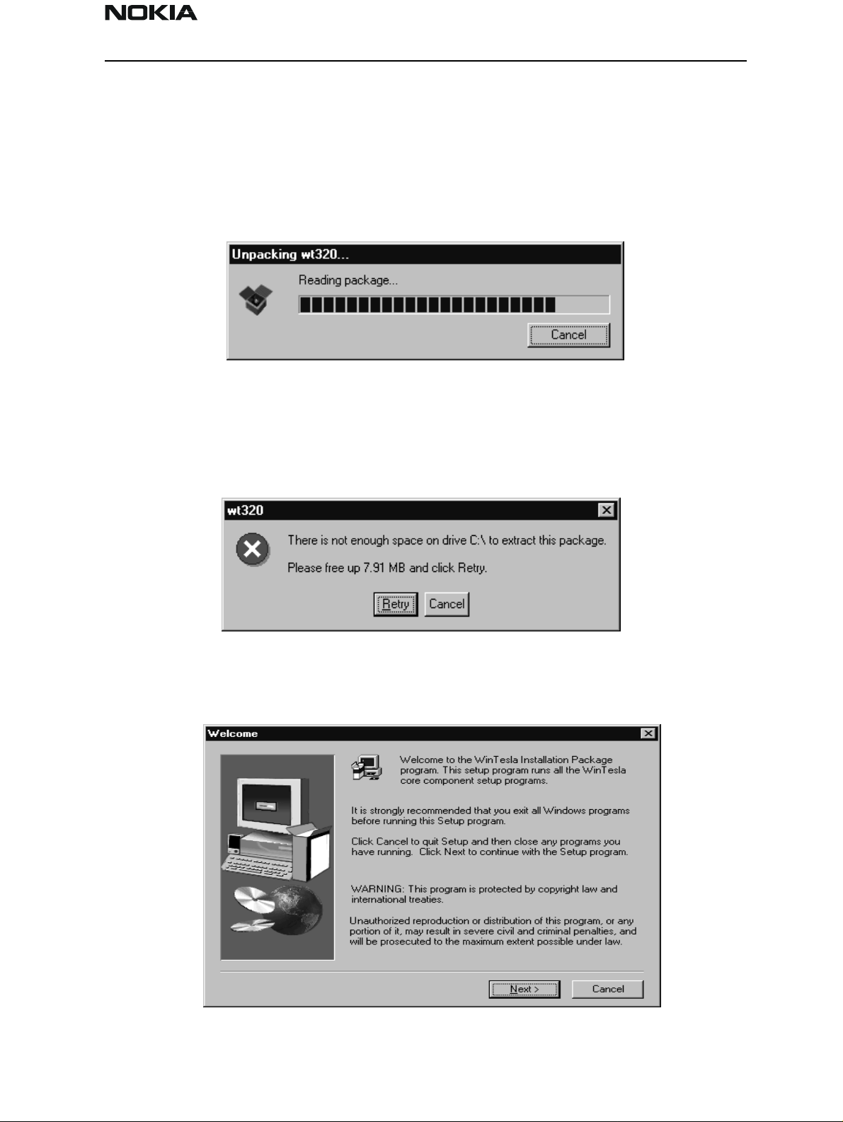
Step 1:.
The installation file will be identified as wtxxx.exe or, as in this example, wt320.
Double click on this file and the unpacking dialog box should appear as follows:
The installation package requires that the system C:\ driv e have a minimum of 10 MB
available disk space; otherwise, an error dialog box, as in the example below, will appear:
Step 2:
Next, the “Welcome” dialog box appears. Click the Next > button to continue:
Issue 1 04/01 Nokia Mobile Phones Ltd. Page 7
Page 8
NSD-6
Service Software and Tuning Instructions PAMS Technical Documentation
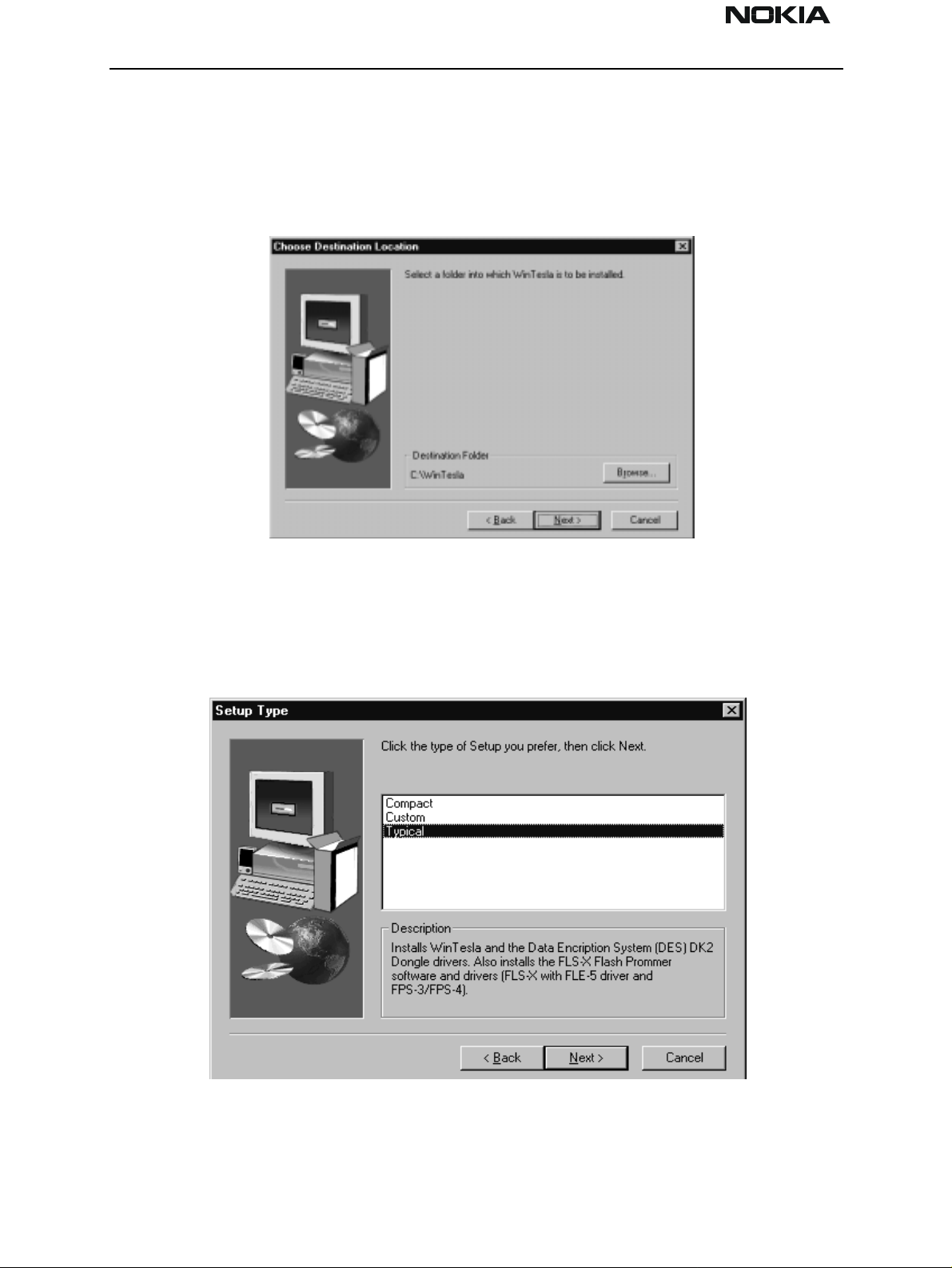
Step 3:
You can either accept the default location for WinTesla software or specify your own
location. Use the Browse button to locate and select the desired destination folder.
Select the Next > button to continue, the < Back button to return to the previous dialog, or the Cancel button to exit.
Step 4:
If the Next > button was selected, the “Setup Type” dialog box is displayed. You can
choose “Compact” to install the minimum requirement files to use WinTesla, “Custom” to
install only your favorites, or “Typical” to install WinTesla automatically. “Typical” is
highly recommended.
Select the Next > button to continue, the < Back button to return to the previous dialog, or the Cancel button to exit.
Page 8 Nokia Mobile Phones Ltd. Issue 1 04/01
Page 9
NSD-6
PAMS Technical Documentation Service Software and Tuning Instructions
:
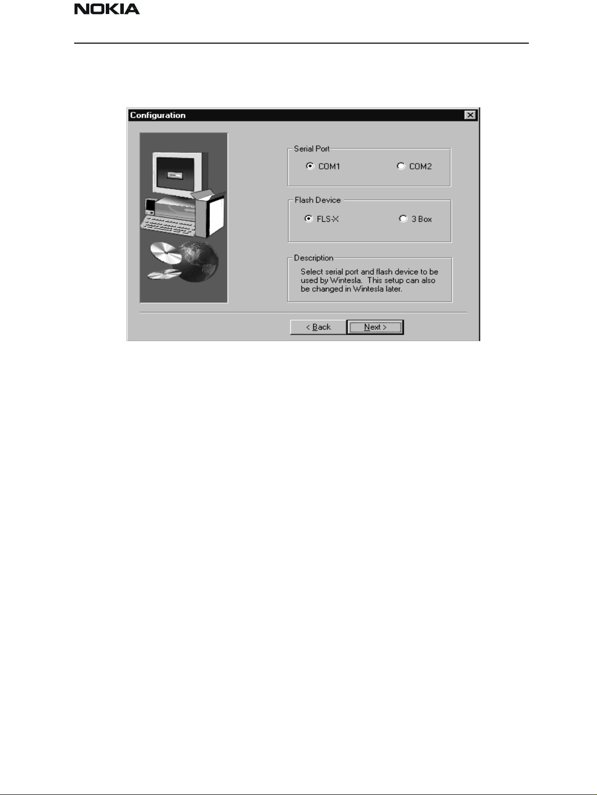
Step 5
If the Next > button was selected, the “Configuration” dialog box is displayed.
Choose the appropriate serial port and flash device by clicking on the appropriate radio
button. Then, select the Next > button to continue or the < Back button to return to the
previous dialog. Note: These selections can be changed later in the Configuration Menu.
Step 6:
After the installation process is finished, select RESTART to reboot the system.
After doing this complete package installation, the next step will be "Phone Specific Ser-
vice Module for NSD-6.”
WinTesla DLL Module Updates
Purpose of Updates
Occasionally, new versions of WinTesla CDMA dll will be released. These new versions
may be required to service new models of phone s , to incorporate new features, or to
improve the software from a previous version.
It is very important to obtain the new releases as they become available and install them
in your system. Failure to do so may cause problems with WinTesla operation.
Installing a New WinTesla dll
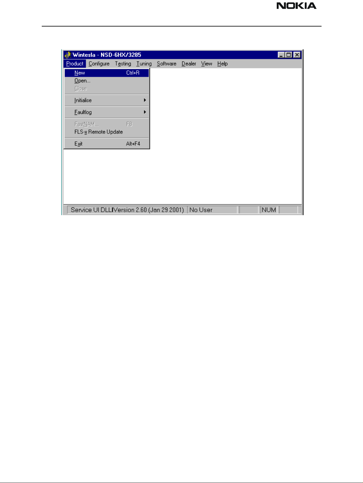
1. Verify which version your setup currently is using by executing WinTesla with a phone
connected. Select the “Product” drop–down menu and click ”New”. Once WinTesla has
communicated with the phone, the current ve rsion of dll will be displayed in the action
bar located in the lower left corner of screen.
Issue 1 04/01 Nokia Mobile Phones Ltd. Page 9
Page 10

NSD-6
Service Software and Tuning Instructions PAMS Technical Documentation
2. If the version is older than that being released (as indicated in a Field Service Bulletin),
obtain the update file. The file is usually smaller than 2 Meg an d thus can be downloaded from the Partners Web Page, http://americas.partners.nokia.com.
3. Save the file to any folder on the computer.
4. Double click on the saved file. This will automatically install the updated software into
the appropriate WinTesla folders.
Phone Specific Service Module for NSD–6
Using WinTesla with NSD-6 phones
The WinTesla application, “WinTesla.exe”, is phone independent. It relies on separate,
phone specific, “modules” to provide communication, menus, and test algorithms.
For each phone type – or product family – a phone interface module and menu module
are required. The modularity of WinTesla allows support for other languages, so one
phone type may have one phone interface module and several menu modules, all in different languages.
WinTesla allows you to select the language you wish to use (if available), and will automatically load the correct phone interface module for the connected phone. When a different phone type is connected, WinTesla will load the new phone interface and
associated menus.
Menu Bar
The Service Software package will have two menu bar configurations. The first, is an
abbreviated version that contains the minimum number of menus that allows package
configurations when a phone is NOT connected. The second is described below:
The menu bar MUST only contain the following menus for the Service Software package
when a phone is connected:
Product*
Configure*
Tuning (not available with PKD–1D)
Testing (not available with PKD–1D)
Software
Dealer
View
Page 10 Nokia Mobile Phones Ltd. Issue 1 04/01
Page 11
NSD-6
PAMS Technical Documentation Service Software and Tuning Instructions
Help*
* – always displayed, even if the phone is not connected.
The menu is broken down into sections that are indicated with menu separators. Each
section identifies a logical difference from itself and other sections, i.e. between transmitter and receiver. Any items that are required to be added to a menu lists will be added
to the bottom of the appropriate menu section list. If a new item is to be added which is
common to two or more phone types, then that menu item will become a common menu
item.
The menu lists will use the Microsoft [...] symbol after an item name to indicate that
selecting that item will NOT initiate an operation immediately. A dialog box will be displayed for the user to select options or type in data and press the OK button before the
operation is performed.
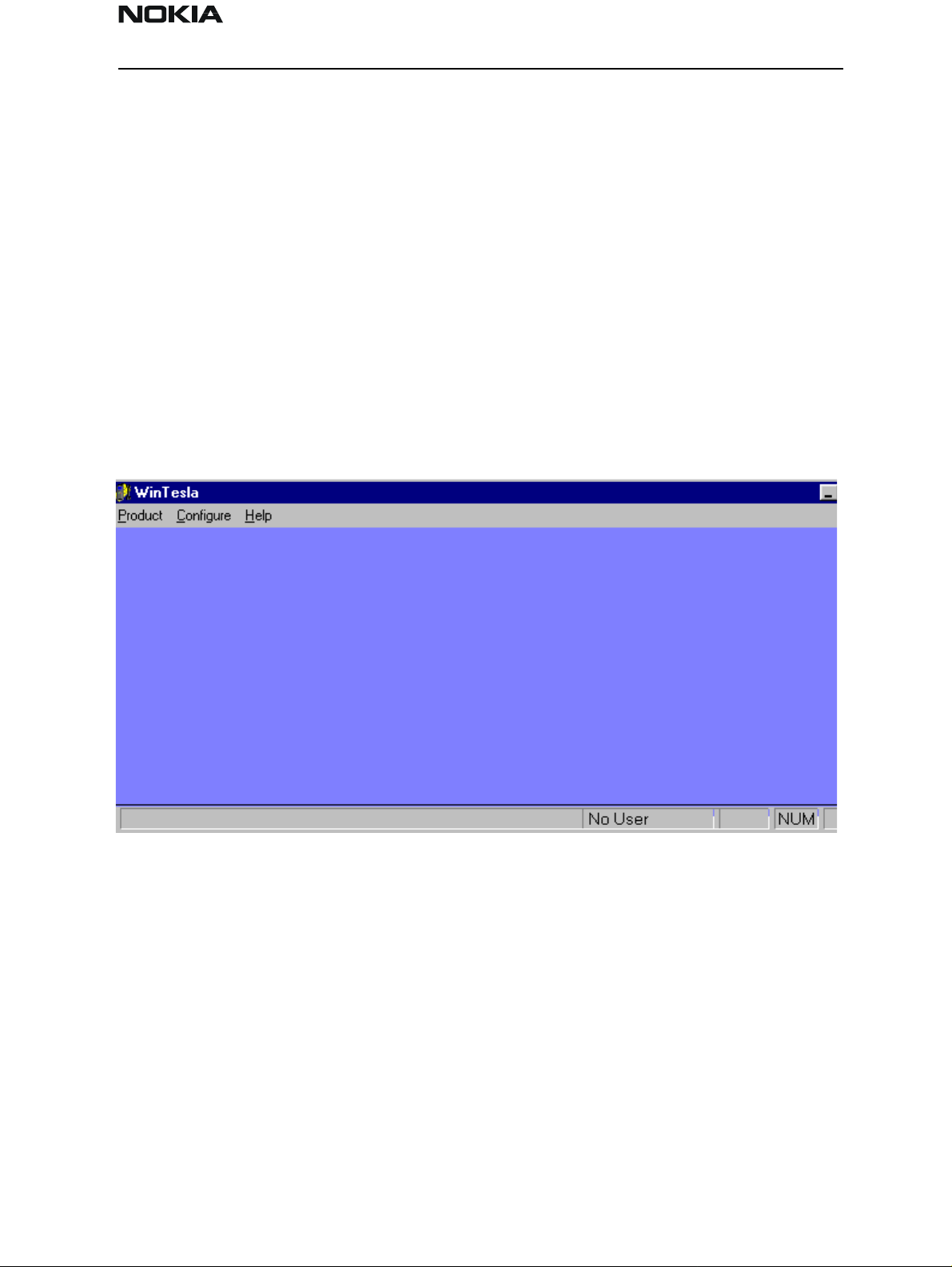
WinTesla Screen
The main WinTesla screen (if no phone is attached) is displayed with three menu items at
the top of the screen and a status bar at the bottom.
The information on the left of the status bar will be used to provide information when
WinTesla is performing tasks: such as reading data from the phone. The status bar also
includes the name of the current user.
Getting Started
Setup for BUS type and COM port:
NOTE: This section can be skipped typically. Use it only if there are some changes needed,
such as using a different COM port or using different service accessories (e.g., FLS-2D
instead of FPS-4 (3 box flashing)) setup. When you have installed the WinTesla core software with PKD–1 drivers and the product specific DLL software, the next step is to tell
the software what kind of hardware connection you are using.
Issue 1 04/01 Nokia Mobile Phones Ltd. Page 11
Page 12
NSD-6
Service Software and Tuning Instructions PAMS Technical Documentation
1. Select the correct COM Port. For example, COM1.
2. Select the Hardware Type. For example, service cable DAU–9P (>>DAU for MBUS).
3. Select the Media, For example, MBUS.
4. Press Add to save configuration.
When you start using the WinTesla program with a new phone you should:
1. Select New, then the program starts to scan the phone that has been connected to the
PC or;
2. Select Open. Then you need to select the right product type, i.e.; NSD–6.
After the product specific DLL has been selected, it will be displayed on the bottom of the
PC screen. The version and date of the Product-specific DLL is also displayed.
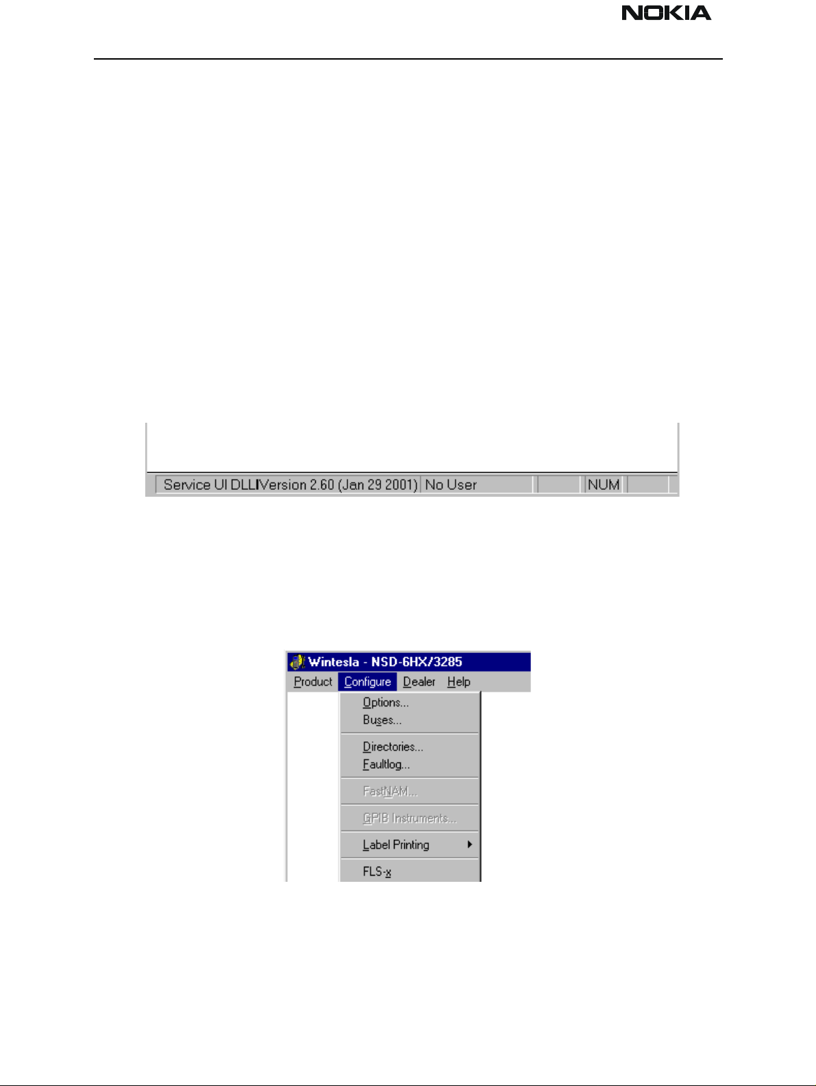
Configure Menu
NOTE: This section can be skipped typically. Use it only if there are some changes needed,
such as using a different COM port or using different service accessories (e.g., FLS-2D
instead of FPS-4 (3 box flashing)) setup. The configuration menu allows you to setup
such things as directory paths, user interface language and FaultLog options.
Page 12 Nokia Mobile Phones Ltd. Issue 1 04/01
Page 13
NSD-6
PAMS Technical Documentation Service Software and Tuning Instructions
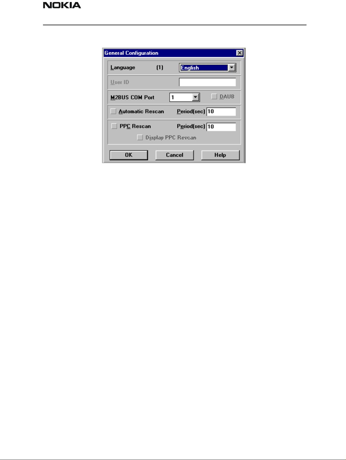
Options
Language
This option allows you to change the language used in the WinTesla application.
User ID
Allows the user ID to be entered if the user’s name is setup in the opt_id.val (validation)
file.
M2BUS COM Port
This option allows you to select which communications port the phone is to be connected. The change will take place immediately after pressing the OK button.
Automatic Rescan
Automatic rescan is a mechanism to automatically check for the new phone; the time
between re–scans is user configurable. When a phone is scanned and recogni ze d, the
corresponding phone interface and menu are loaded, extending the main menu at the
top of the screen and displaying the phone type and description at the bottom of the
screen.
The Product|New (or Ctrl+R ) function can be used to rescan the phone in–between automatic rescans or when automatic rescan has been disabled. The automatic re–scan
mechanism is disabled when the Product|Open function is used to load a phone interface.
Check in the automatic rescan box enables the automatic rescan option. Clicking on the
check–box (making the check–box blank) will disable the automatic re–scan option. The
time between re–scans (in seconds) is entered into the edit box.
Pressing the OK button will save any changes made. Pressing the CANCEL button will
discard any changes you may have made.
Issue 1 04/01 Nokia Mobile Phones Ltd. Page 13
Page 14
NSD-6
Service Software and Tuning Instructions PAMS Technical Documentation
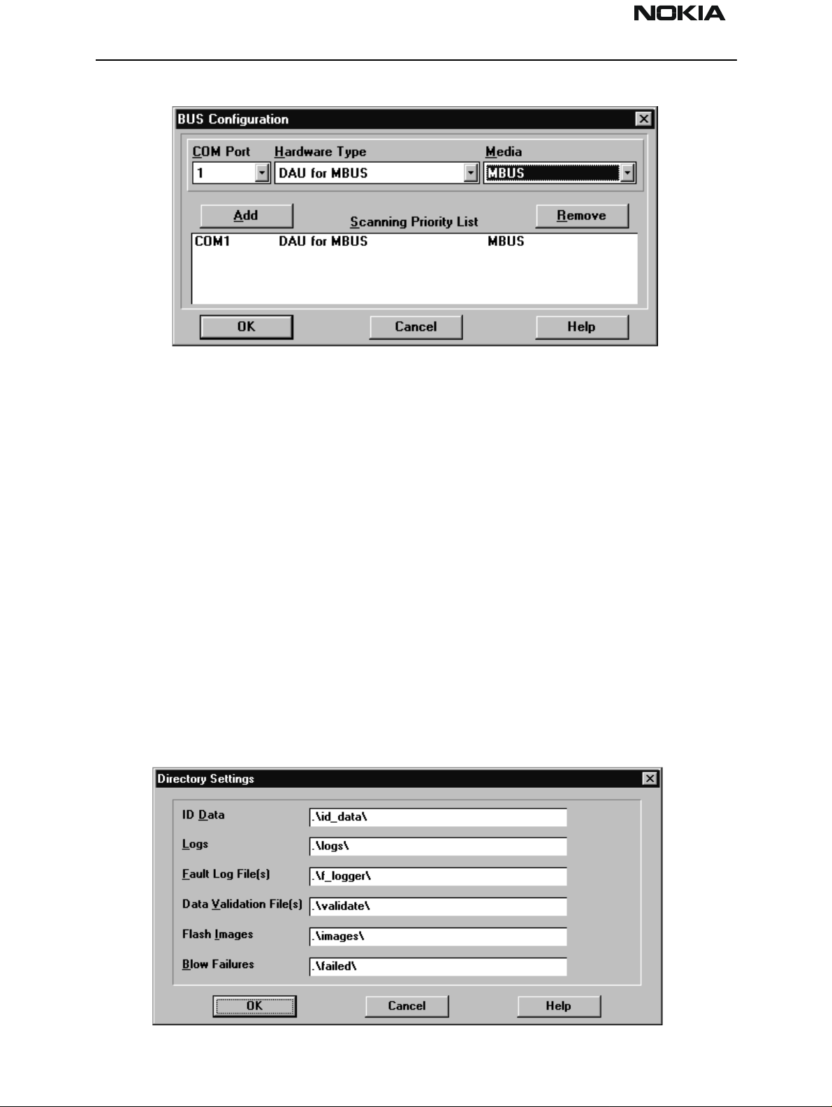
Buses
Setup for BUS type and COM port:
NOTE: This section can be skipped typically. Use it only if there are some changes needed,
such as using a different COM port or using different service accessories (e.g., FLS-2D
instead of FPS-4 (3 box flashing)) setup. When you have installed the WinTesla core software with PKD–1 drivers and the product specific DLL software, the next step is to tell
the software what kind of hardware connection you are using.
1. Select the correct COM Port. For example, COM1.
2. Select the Hardware Type. For example, service cable DAU–9P (>>DAU for MBUS). In
case of FLS–1 select also DAU for MBUS. IN case of 3–box flash concept select Combox
for MBUS.
3. Select the Media, For example, MBUS.
4. Press Add to save configuration.
Directories
This function allows you to organize your data into different directories.
Page 14 Nokia Mobile Phones Ltd. Issue 1 04/01
Page 15
NSD-6
PAMS Technical Documentation Service Software and Tuning Instructions
The directories already exist when the WinTesla core software is installed. If an invalid
directory is entered, then an error message will be displayed.
The use of a backslash (‘\’) at the end of the directory name is optional. Clicking on the
OK button will save your changes.
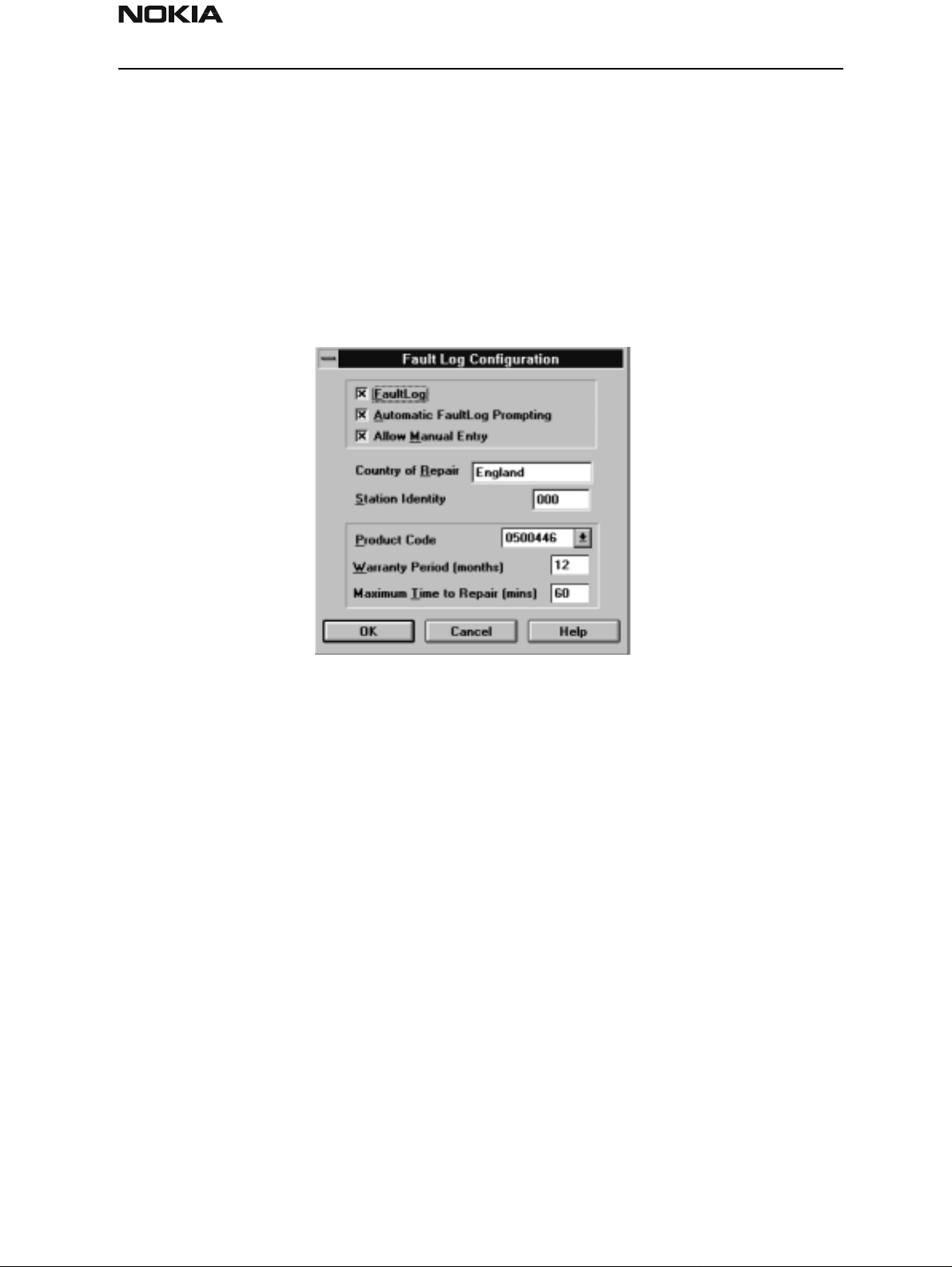
Fault Log Configuration (needed only if fault logger system in use)
If the fault logger is not used, please jump to section "The Product Menu". Fault Log is a
feature that allows the PC to create a record of each phone that is serviced for historical
tracking. This function allows you to configure the Fault Log mechanism. Clicking OK
after making selections, saves all changes made.
Fault Log
This option allows you to enable or disable the Fault Log mechanism. Choosing to disable
the Fault Log mechanism results in the options being ‘greyed’ and the F9 button being
disabled.
Allow Manual Entry
This option allows you to disable manual entry of data that was unavailable from the
phone.
Automatic Fault Log Prompting
Enabling this option results in a prompt being displayed if the phone has changed.
Station Identity
Enter the unique identity of your ‘workstation’; this ID is used to write Fault Log files.
Country Of Repair
Enter the country of repair.
Warranty Period ( months )
Each product code has an associated warranty period. This option allows you to change
those warranty periods. If no phone is connected then all product codes supported will
Issue 1 04/01 Nokia Mobile Phones Ltd. Page 15
Page 16

NSD-6
Service Software and Tuning Instructions PAMS Technical Documentation
be displayed. However, if a phone is connected then only the product codes associated
with that phone type are displayed.
Note: Changing the Warranty Period in the Fault Log data file has no effect on the product’s warranty terms as stated from the manufacturer.
Maximum Time To Repair ( minutes )
Enter the maximum time allowed to repair a phone.
Fault Log Application
The aim of the Fault Log application is to provide NMP After Market Services companies
worldwide a standard method for the collection of Fault and Repair Data from their service processes. This information can also be used by NMP R&D and Manufacturing organizations as well.
The Fault Log application can be regarded as a data entry subroutine run from the WinTesla Service Software package at the end of a repair. This allows for quick and uniform
recording of the service performed on the product.
Each product repaired will generate one unique record in a Fault Log file consisting of up
to 37 data fields containing information about the product and how it was repaired. This
information is read automatically where possible, from the product’s own internal
EEPROM, and then entered manually by the service technician to form a complete service record.
For more advanced implementations, the repair records are copied and collected by the
electronic mail system installed in the Service Center and are sent electronically to a
Central Service Database located in Finland.
Completing a FaultLog Record
Once WinTesla has been configured correctly, it operates in the following manner:
• WinTesla automatically reads the product details from the product’s EEPROM and
writes them as a record to a pre–determined file.
• Proceed with the repair task, utilizing a combination of software-driven tuning and
hardware modifications.
On completion of the repair task you have a choice:
A. With the product still connected to the PC, manually display the repair data entry
screen by selecting Function Button F9.
B. Alternatively, the product can be disconnected and the next product for repair con-
nected in its pl a ce .
As long as Automatic Prompting is enabled, the previous product’s repair data entry
screen will be displayed.
Page 16 Nokia Mobile Phones Ltd. Issue 1 04/01
Page 17
NSD-6
PAMS Technical Documentation Service Software and Tuning Instructions
Enter the repair work performed on the product in the repair data screen.
Check the automatic data for this product, read earlier, to ensure its accuracy.
When satisfied with the data, save the entry. This process adds a complete record con-
taining the product details and the repair details to the Fault Log output file.
The output file can then be manipulated by a number of different systems, as required, as
a detailed record of the product fault.
To attempt to record all of this information, 37 data fields are defined for each Fault Log
record. These can be split as follows:
• Product definition information fields
• Repair / fault information fields
Most products have their information stored in EEPROM. WinTesla automatically reads
this information from the EEPROM and writes it to the Fault Log record. This part of the
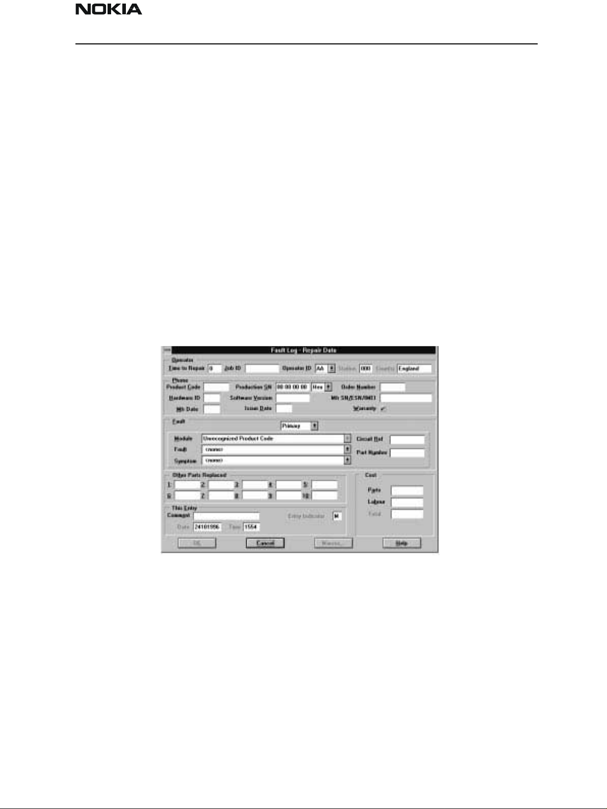
record is shown below.
Fields that are ‘greyed out’ are data that has been automatically retrieved from the
phone’s EEPROM. All other fields are entered manually; fields are summarized below.
Operator
Automatic: Station, Country
Manual: Time to repair, Job ID, Operator ID
Phone
Automatic: Product code, Production SN, Order No., Hardware ID, Software version,
Mfr. SN/ESN/IMEI, Mfr. Date, Issue date
Issue 1 04/01 Nokia Mobile Phones Ltd. Page 17
Page 18
NSD-6
Service Software and Tuning Instructions PAMS Technical Documentation
Manual: Warranty
Fault
Automatic: none
Manual: Module, Fault, Symptom, Circuit ref., Part Number
The current Fault Log application allows for the entering of three priority levels of fault /
repair information seen as Primary, Secondary, and Tertiary faults.
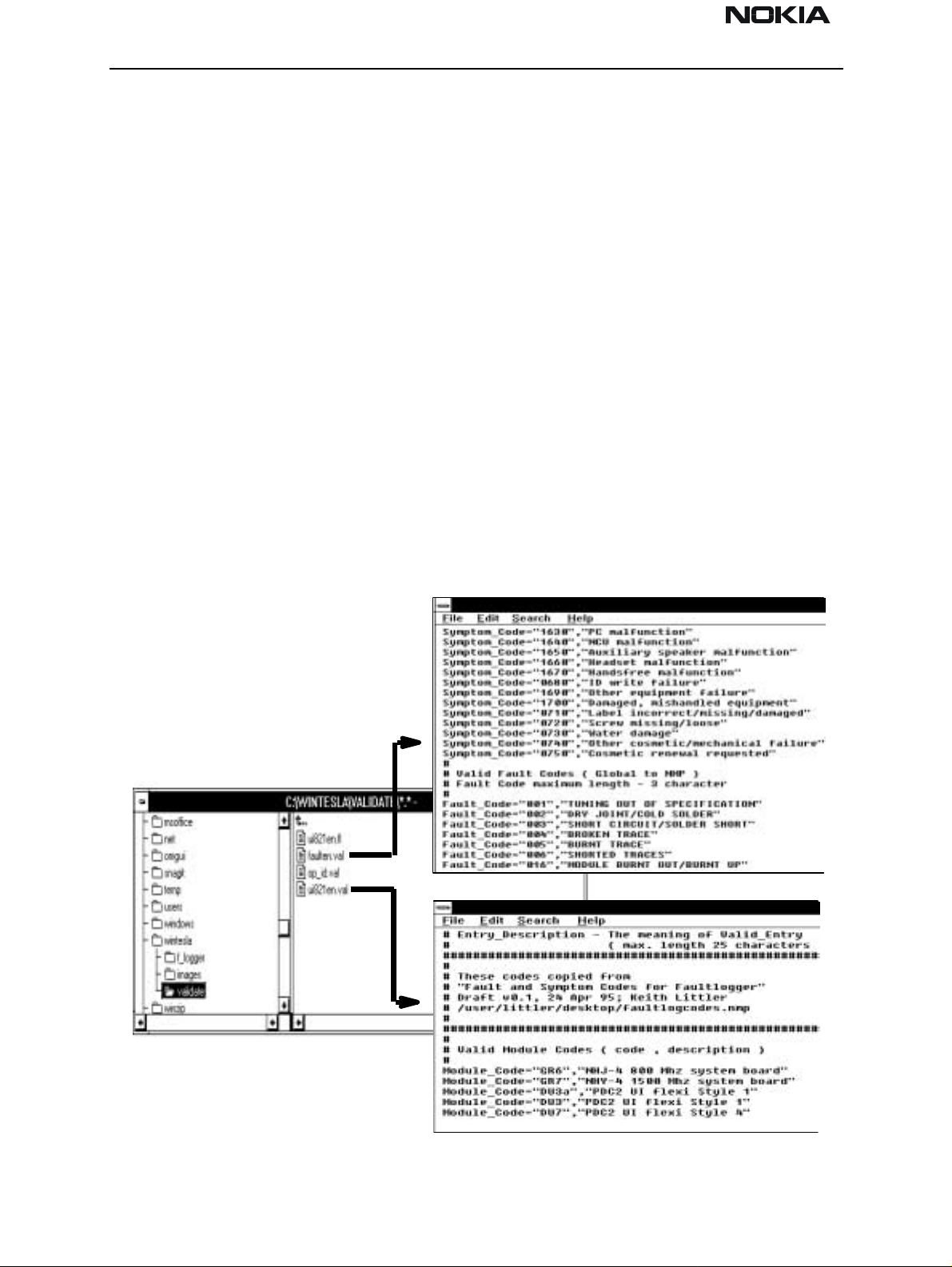
The Module, Fault, and Symptom fields have variables selected by the arrows alongside
each respective field.
A comprehensive list of faults and symptoms as well as all current modules are already
listed within the software. These three fields can be updated by accessing and editing the
following files.
Field DOS File
Modules nhd4en.val
Faults, Symptoms faulten.val
Notepad – FAULTEN.VAL
Notepad – UI821EN.VAL
Page 18 Nokia Mobile Phones Ltd. Issue 1 04/01
Page 19

NSD-6
PAMS Technical Documentation Service Software and Tuning Instructions
Other Parts Replaced
Automatic none
Manual all fields
Enter other parts that have been replaced i.e. for wear and tear purposes etc.
This Entry
Automatic Entry Indicator, Date, Time
Manual Comment
Cost
Automatic Total
Manual Parts, Labor
Fault Log Macros
The Macro sub–menu can be accessed by selecting the Macros button on the Fault Log
main screen.
Macros in Fault Log are a set of standard repair actions defined and stored in order to
represent frequently repeated repairs. These macros are related to the Product Code of
the product, so whatever product is connected, Fault Log will display the macro list for
that particular product code.
A macro’s standard repair information can also be pasted into the Fault Log record for
that product.
Macros are saved initially under a name you can define yourself from the main Fault Log
screen. All the information contained in the manually entered fields (i.e., Module, Fault,
Symptom, Circuit Ref and Part Number) are recorded and saved under this name.
Flash Device
This function is for selecting the right flash concept. The default setting is POS flash and
is based on FLS–1 device connected to the parallel por t of the PC.
If the FPS–4, FLA–5, and TDF–4 flash device is used, then the setup 3–box is needed to
select.
Issue 1 04/01 Nokia Mobile Phones Ltd. Page 19
Page 20
NSD-6
Service Software and Tuning Instructions PAMS Technical Documentation
The Product Menu
New (Ctrl+R)
The ‘New’ function (which can also be activated by pressing Ctrl+R) is used to scan for a
phone when either the automatic rescan option is off or the automatic rescan timer has
not expired (see Configure>Options section for automatic rescan).
If the phone type is unrecognized or unsupported by the current WinTesla system, then a
warning message will be displayed.
If the phone is changed (with the same phone type only the serial number is changed),
the phone will be initialized into local mode. If the phone is changed to a different phone
type, the current DLLs are unloaded and new ones are loaded for that phone.
If the Quick/RF Info view is open, the window will be automatically updated.
If the Phone Information view is open, it will be automatically updated.
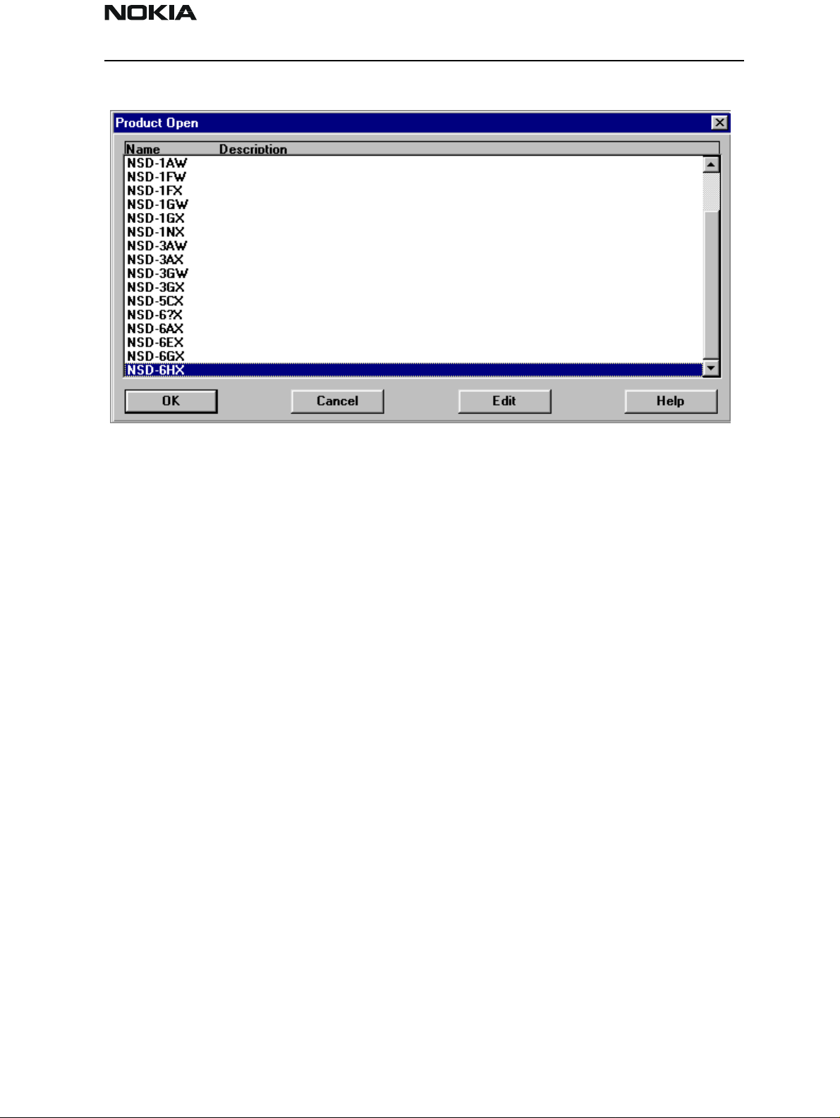
Open
The ‘Open’ function allows you to ‘force load’ a phone interface, even if there is no phone
connected to the system.
Page 20 Nokia Mobile Phones Ltd. Issue 1 04/01
Page 21
NSD-6
PAMS Technical Documentation Service Software and Tuning Instructions
A dialog box will appear and a list of supported phone types. To select a particular phone,
highlight the phone type name and click OK.
Clicking on Cancel will stop the request and no new phone type will be loaded.
Loading a phone interface will disable the automatic rescan function (see Config-
ure>Options section for automatic rescan).
Close
This function will close the currently loaded phone type interface that had been loaded
using the Configure>Options function. You cannot ‘Close’ a loaded phone type interface
if it was loaded by a rescan.
Initialize
Activation Status Bar Text
Alt, P, I Opens a submenu for the Normal Mode and the Local Mode.
Normal Mode
Activation Status Bar Text
Alt, P, N Initializes the phone to normal (cellular) mode F5.
When the normal mode has been activated or the program has been started, self–test
results will be gathered from the MCU. If any fault was found in the tests, an error message is shown. If the normal mode has been set successfully (no self–test error has been
found), and paging listening has been started, the used AFC value is requested from MS.
Initialization routine checks the phone’s cellular type and, if it is unsupported, the phone
Issue 1 04/01 Nokia Mobile Phones Ltd. Page 21
Page 22

NSD-6
Service Software and Tuning Instructions PAMS Technical Documentation
application unloads the DLLs.
The After Market Services SW automatically sets the MS state to normal mode when
needed.
If the phone identification view is open, the window will be updated automatically. Also,
if the RF Information Window is open, it will be updated t o qu ick info view.
Local Mode
Activation Status Bar Text
Alt, P, L Initializes phone to local mode
Shift + F5
Selection will change the MS state to local. When the user selects item from Testing or
Tuning menus, the After Market Services SW software will automatically change the MS
state to local.
The After Market Services SW automatically sets the MS state to normal mode when
needed.
Also, if quick info view is open, it will be updated to RF Information view.
FaultLog
Activate Fault Log
Edit Fault Log
This function is only needed if fault logger system is in use.
Exit (Alt+F4)
Selecting this option will shut down the WinTesla program.
Page 22 Nokia Mobile Phones Ltd. Issue 1 04/01
Page 23
NSD-6
PAMS Technical Documentation Service Software and Tuning Instructions
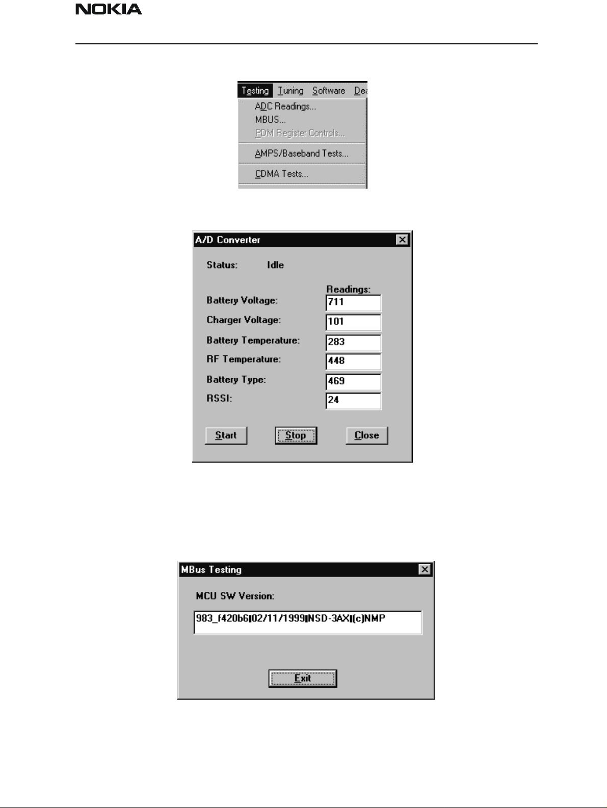
The Testing Menu
ADC Readings
MBUS
This option allows the phone’s ADC readings to be displayed. The readings are updated
every few seconds. There may be some delay before the mouse or keyboard responds
while running this test.
Mbus displays the MCU software version.
Issue 1 04/01 Nokia Mobile Phones Ltd. Page 23
Page 24
NSD-6
Service Software and Tuning Instructions PAMS Technical Documentation
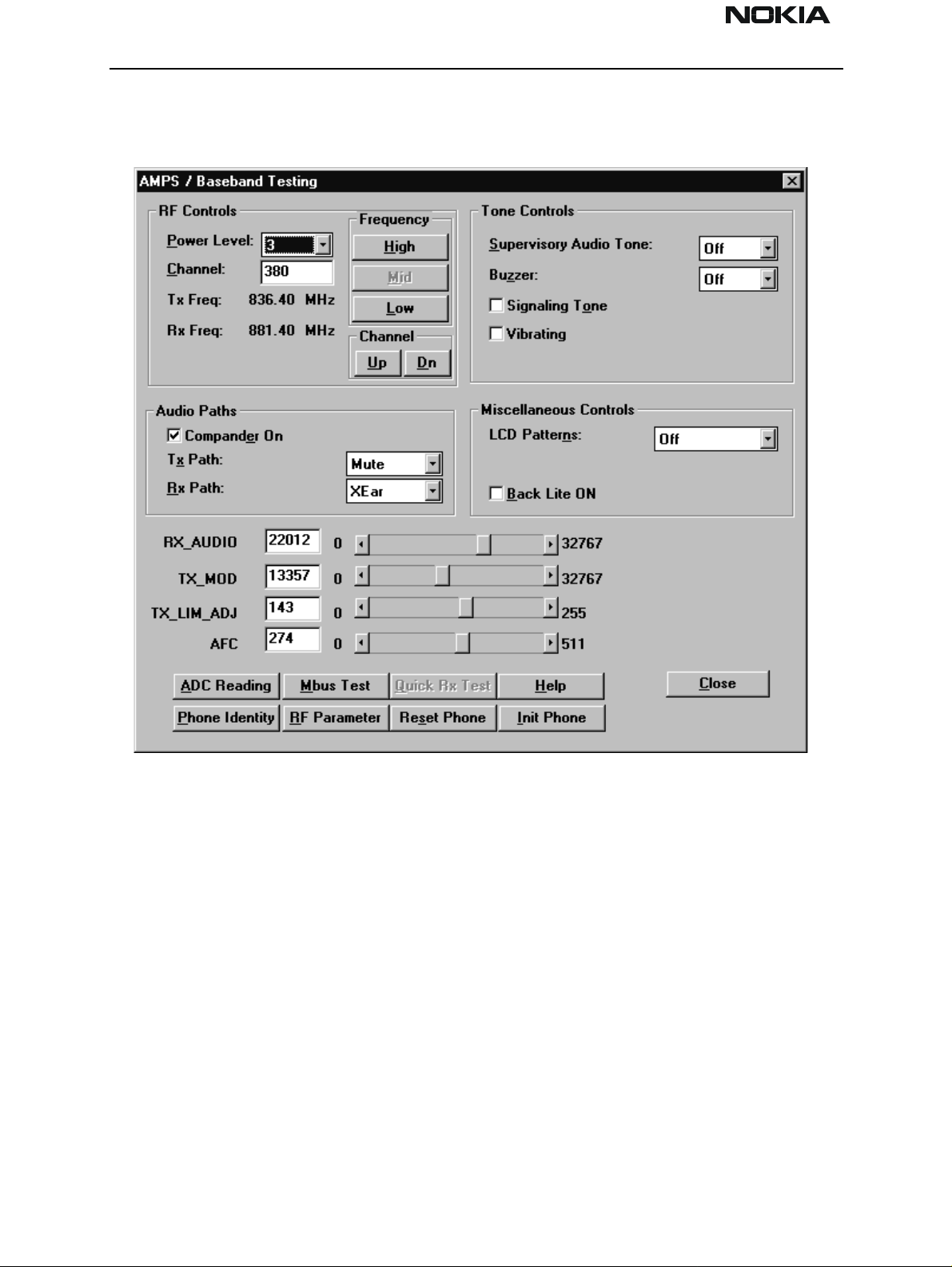
AMPS / Base Band Tests
This screen is used when testing and troubleshooting the phone in AMPS mode. Below is
an example screen.
RF Controls:
Power Level – Turns the transmitter on/off and sets power levels.
Channel – Changes the AMPS channel of the phone.
TX Freq: Displays the current Transmit Frequency.
RX Freq: Displays the current Receiver Frequency.
Frequency:
High – Sets the AMPS channel to the Highest Frequency according to the Frequency
planning set in the “configure” menu.
Mid – Sets the AMPS channel to the Middle Frequency according to the Frequency planning set in the “configure” menu.
Low – Sets the AMPS channel to the Lowest Frequency according to the Frequency plan-
Page 24 Nokia Mobile Phones Ltd. Issue 1 04/01
Page 25

NSD-6
PAMS Technical Documentation Service Software and Tuning Instructions
ning set in the “configure” menu.
Channel:
Up – Increments the channel selection by one.
Dn – Decrements the channel selection by one.
Tone Controls:
Allows computer control of Supervisory Audio Tone (SAT), buzzer, Signaling Tone (ST),
and vibrating functions.
Audio Paths:
TX Path: – Allows the user to control the TX Audio path (Mute, Ear, External Ear).
RX Path: – Allows the user to control the Rx Audio path (Mute, Ear, External Ear).
Miscellaneous Controls:
Buttons:
Allows control of LCD patterns, call LED and backlight.
ADC Reading
Opens the ADC reading screen.
Mbus Test
Tests the communication between the phone and the computer.
Phone Identity
Opens the Quick Receiver test screen.
RF Parameter
This function allows reading the saved RF parameters (tuning values) from the phone.
Reset Phone
Resets the phone.
Init Phone
Initializes the phone.
Close
Exits the current screen.
Issue 1 04/01 Nokia Mobile Phones Ltd. Page 25
Page 26
NSD-6
Service Software and Tuning Instructions PAMS Technical Documentation
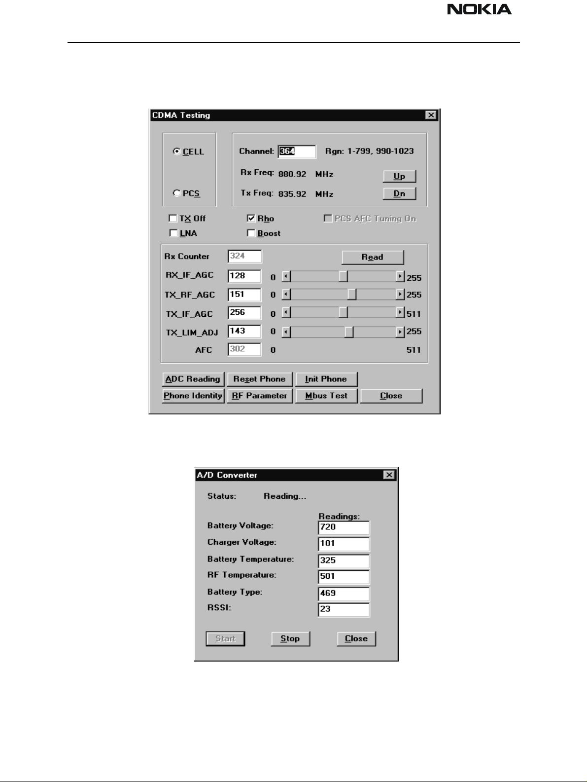
CDMA Tests
This screen is used when testing and troubleshooting the phone in CDMA mode. Below is
an example screen.
ADC Readings
This option allows the phone’s ADC readings to be displayed. The readings are updated
every few seconds. There may be some delay before the mouse or keyboard responds
while running this test.
Page 26 Nokia Mobile Phones Ltd. Issue 1 04/01
Page 27
NSD-6
PAMS Technical Documentation Service Software and Tuning Instructions
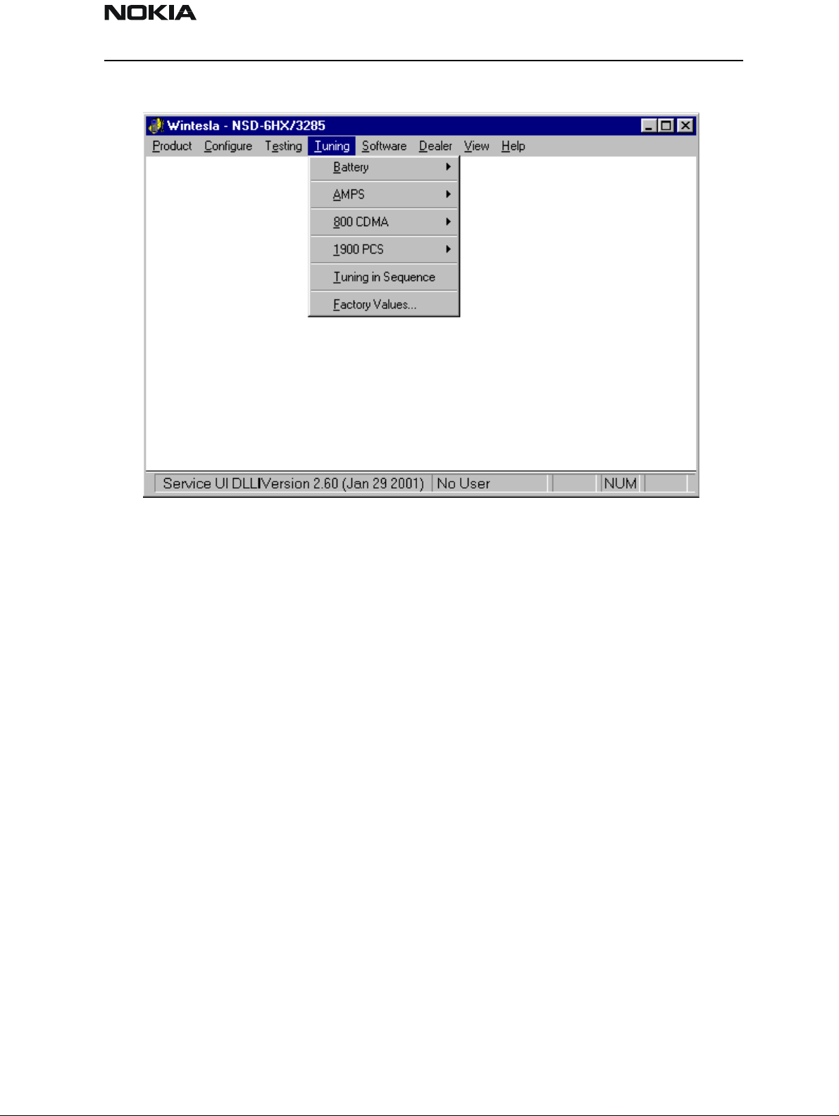
The Tuning Menu
Tuning Steps of Radio Unit
The Service Software program places the phone into the Local mode, in which the phone
can be outwardly controlled via M2BUS interface.
The tuning values of the phone reside on the EEPROM. Before tuning, the Service Software reads these values and the user can change these values with tuning functions.
NOTE: During tuning, keep the following in mind:
• Take care not to damage sensitive measuring instruments with excessive RF power.
• Carry out all tuning steps in the shortest possible time to avoid excessive heating of RF
units.
• Perform all tuning steps in the order presented.
• Never try to mask a fault by tuning it out.
Accuracy of the Equipment during Measurement
• Power supply 1; nominal voltage 8.0V ±0.2V , minimum current capacity 1.5A for ser-
vice battery BBD–3.
• Power Supply 2; nominal voltage 4.1 ±0.1V, minimum current capacity 1.5A for testing
dummy battery BTD–3.
• Modulation analyzer; power level resolution 0.1dB, accuracy ±0.5dB. Frequency
Issue 1 04/01 Nokia Mobile Phones Ltd. Page 27
Page 28

NSD-6
Service Software and Tuning Instructions PAMS Technical Documentation
counter accuracy 0.1ppm (±80Ηz).
• RF generator; frequency resolution 10Hz amplitude resolution 0.1dB frequency stabili-
zation ±0.25ppm.
• Spectrum analyzer; dynamic range 7 0dB, accuracy ±1dB (For power level measurement
accuracy ±0.5dB).
Battery Tuning
Battery Voltage Tuning
A reference value for the battery is calibrated by using BDD–3 service battery.
NOTE: Calibration of the A/D converter channels as follows:
• Connect the cable SCB–3 from service battery to the charging connector. Apply +1 0.5V
to the service battery.
• Select Tuning > Battery > Tuning Battery.
• Select ”Tune”
• The program reads the voltage and current and displays the corresponding A/D reading
fed to the phone via the VBATT line.
• Store this new value to the phone by selecting the Tune button. Then press the Save &
Exit button.
Page 28 Nokia Mobile Phones Ltd. Issue 1 04/01
Page 29

NSD-6
PAMS Technical Documentation Service Software and Tuning Instructions
Charging Voltage and Current Tuning
A reference value for the battery is calibrated by using BDD–3 service battery.
Calibration of the A/D converter channels as follows:
• Connect the cable SCB–3 from service battery to the charging connector. Apply +1 0.5V
to the service battery.
• Select: Tuning > Battery> Tuning Charge.
• The program reads the voltage and current, and displays the corresponding A/D reading
fed to the phone via the VBATT line.
• Store this new value to the phone by selecting the Tune button. Then press the Save &
Exit button.
Issue 1 04/01 Nokia Mobile Phones Ltd. Page 29
Page 30

NSD-6
Service Software and Tuning Instructions PAMS Technical Documentation
AMPS Tunings
AFC (Automatic Frequency Control)
Set up spectrum analyzer as follows:
Center frequency Frequency in tuning window
Span 20 KHz
Amplitude Reference level 30 dBm
Attenuation Auto
Amplitude level offset 0 dB
Resolution bandwidth (RBW) Auto
Video bandwidth (VBW) Auto
Sweep time Auto
Marker track On
Page 30 Nokia Mobile Phones Ltd. Issue 1 04/01
Page 31

NSD-6
PAMS Technical Documentation Service Software and Tuning Instructions
Connect Spectrum Analyzer to phone’s antenna connector.
Press PEAK SEARCH button if marker is not on signal’s peak.
Tune using Up, Dn, PgUp and pgDn buttons until marker frequency is within target range.
Tx Power Level
NOTE: This window was taken from WinTesla with the cable loss set at 0.7dB. The power
levels tuned at the phones RF connector are:
Power
level
0-2 26.2 dBm +/- 0.15 dB
3 24 dBm +/- 0.5 dB
4 20 dBm +/- 0.5 dB
5 16 dBm +/- 0.5 dB
6 12 dBm +/- 0.5 dB
78 dBm +/- 1 dB
Nom. power
NSD-6GX
Range
Power level 0–2 target value is 25.5dBm (+/–0.15dBm) when 0.7dB cable loss is used.
This level needs to be tuned at six different channels. Refer to the channel info in the
WinTesla SW.
Issue 1 04/01 Nokia Mobile Phones Ltd. Page 31
Page 32

NSD-6
Service Software and Tuning Instructions PAMS Technical Documentation
AMPS Tuning––TX POWER LEVEL:
Set up spectrum analyzer as follows:
Center frequency Use channels indicated in the PC screen
Span 20 KHz
Amplitude Reference level 30 dBm
Attenuation Auto
Amplitude level offset 0 dB
Resolution bandwidth (RBW) Auto
Video bandwidth (VBW) Auto
Sweep time Auto
Marker track On
Connect Spectrum Analyzer to phone’s antenna connector.
Press PEAK SEARCH button if marker is not on signal’s peak.
Select power level to be tuned.
Tune using Up, Dn, PgUp and PgDn buttons until marker power is within target range.
Tx Modulation Index
AMPS Tuning––TX MODULATION INDEX:
Set up communication analyzer (HP8924, HP8920 etc) as follows:
Page 32 Nokia Mobile Phones Ltd. Issue 1 04/01
Page 33
NSD-6
PAMS Technical Documentation Service Software and Tuning Instructions
Select DUPLEX under Analog Screen.
Channel Channel number in tuning window
IF filter 15KHz
AF Anl in FM Demod
Filter 1 300Hz HPF
Filter 2 6KHz BPF
De_amphasis ON
Detector +/– Max
Connect communication analyzer’s output to phone’s antenna connector.
Tune using Up, Dn, PgUp and PgDn buttons until frequency deviation is within target
range.
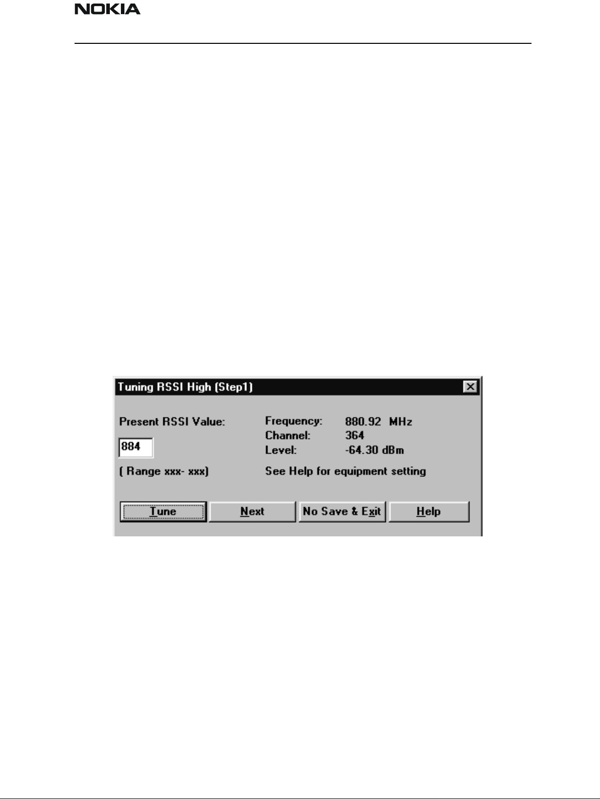
RSSI (Received Signal Strength Indicator)
AMPS Tuning–RSSI Step 1
Set up communication analyzer (HP8924, HP8920 etc) as follows:
Select DUPLEX under Analog Screen.
Level offset Off
Channel Channel number in tuning window
Amplitude Level in tuning window
Audio freq 1KHz
Issue 1 04/01 Nokia Mobile Phones Ltd. Page 33
Page 34

NSD-6
Service Software and Tuning Instructions PAMS Technical Documentation
AF Anl out FM
Freq. Deviation 2.6KHz
Connect communication analyzer’s output to phone’s antenna connector:
Step 1. Press Tune button. Press Next button to go to Step 2.
Step 2. Set communication analyzer output amplitude to new level. Press Tune button.
The tuning value should be between 570 − 970.
AMPS Tuning–RSSI Step 2
Set up communication analyzer (HP8924, HP8920 etc) as follows:
Select DUPLEX under Analog Screen.
Level offset Off
Channel Channel number in tuning window
Amplitude Level in tuning window
Audio freq. 1KHz
AF Anl out FM
Freq. Deviation 2.6KHz
Connect communication analyzer’s output to phone’s antenna connector:
Step 1. Press Tune button. Press Next button to go to Step 2.
Step 2. Set communication analyzer output amplitude to new level. Press Tune button.
The tuning value should be between 750 − 1050.
Page 34 Nokia Mobile Phones Ltd. Issue 1 04/01
Page 35

NSD-6
PAMS Technical Documentation Service Software and Tuning Instructions
Rx Audio Gain
AMPS Tuning––RX AUDIO GAIN
Set up communication analyzer (HP8924, HP8920 etc) as follows:
Select DUPLEX under Analog Screen
Level offset Off
Channel Channel number in tuning window
Amplitude Level –50 dBm
Audio freq 1KHz
AF Anl out FM
Freq. Deviation 2.6KHz
AF Anl in Audio in
Filter1 C Message
Filter2 3 KHz LPF
De_amphasis OFF
Detector +/– Max
– Connect communication analyzer’s output to phone’s antenna connector.
– Connect phone’s external EAR to communication analyzer’s AUDIO IN.
– Tune using Up, Dn, PgUp and PgDn buttons until AF level is within target range.
Issue 1 04/01 Nokia Mobile Phones Ltd. Page 35
Page 36

NSD-6
Service Software and Tuning Instructions PAMS Technical Documentation
800 CDMA Tunings
TX IF AGC
CELL TUNING - TX_IF_AGC
Point 1:
Set up spectrum analyzer as follows:
Center frequency Frequency in tuning window
Span 30 MHz
Amplitude Reference level 10 dBm
Attenuation Auto
Page 36 Nokia Mobile Phones Ltd. Issue 1 04/01
Page 37

NSD-6
PAMS Technical Documentation Service Software and Tuning Instructions
Amplitude level offset 0 dB
Resolution bandwidth (RBW) 1 MHz
Video bandwidth (VBW) 300 Hz
Sweep time Auto
Marker track On
Connect Spectrum Analyzer to phone’s antenna connector.
Press Peak Search button if marker is not on signal’s peak.
Tune using Up, Dn, PgUp and PgDn buttons until marker power is within target range.
Point 2:
Keep spectrum analyzer setup unchanged.
Tune using Up, Dn, PgUp and PgDn buttons until marker power is within target range.
TX_LIM_ADJ tuning:
Make following change to spectrum analyzer setup:
Amplitude Reference Level: 30 dBm
For each new frequency, press Peak Search button if marker is not on signal’s peak.
Tune using Up, Dn, PgUp and PgDn buttons until marker power is within target range.
LNA Switch
CELL TUNING - LNA GAIN SWITCH
Set up communication analyzer as follows:
Select DUPLEX from the Analog Screen.
Issue 1 04/01 Nokia Mobile Phones Ltd. Page 37
Page 38

NSD-6
Service Software and Tuning Instructions PAMS Technical Documentation
Select FREQUENCY in RF DISPLAY under CONFIG.
Level offset Off
Generator frequency Frequency in tuning window
Amplitude Level in tuning window
Connect communication analyzer’s output to phone’s antenna connector.
Press Tune button to tune.
RX IF AGC
CELL TUNING – RX IF AGC
Steps 1,2,3
Set up communication analyzer as follows:
Select DUPLEX from the Analog Screen.
Select FREQUENCY in RF DISPLAY under CONFIG.
Level offset Off
Generator frequency Frequency in tuning window
Amplitude Level in tuning window
Connect communication analyzer’s output to phone’s antenna connector.
Press Tune button to tune.
Press Next button to go to next step. Repeat process with different amplitudes.
Page 38 Nokia Mobile Phones Ltd. Issue 1 04/01
Page 39

NSD-6
PAMS Technical Documentation Service Software and Tuning Instructions
RX IF Compensation
CELL TUNING - RX_IF FREQ COMPENSATION
Set up communication analyzer as follows:
Select DUPLEX from the Analog Screen.
Select FREQUENCY in RF DISPLAY under CONFIG.
Level offset Off
Generator frequency Frequency in tuning window
Amplitude Level in tuning window
– Connect communication analyzer’s output to phone’s antenna connector.
– Press Tune button to tune.
– Press Next button to go to next step. Repeat process with different frequencies.
Issue 1 04/01 Nokia Mobile Phones Ltd. Page 39
Page 40

NSD-6
Service Software and Tuning Instructions PAMS Technical Documentation
1900 MHz CDMA Tunings.
TX IF AGC (1900MHz)
PCS TUNING - TX_IF_AGC
Point 1:
Set up spectrum analyzer as follows:
Center frequency Frequency in tuning window
Span 65 MHz
Amplitude Reference level 10 dBm
Attenuation Auto
Amplitude level offset 0 dB
Resolution bandwidth (RBW) 1 MHz
Video bandwidth (VBW) 300 Hz
Page 40 Nokia Mobile Phones Ltd. Issue 1 04/01
Page 41

NSD-6
PAMS Technical Documentation Service Software and Tuning Instructions
Sweep time Auto
Marker track On
– Connect Spectrum Analyzer to phone’s antenna connector.
– Press Peak Search button if marker is not on signal’s peak.
– Tune using Up, Dn, PgUp, and PgDn buttons until marker power is within target range.
Point 2:
– Keep spectrum analyzer setup unchanged.
– Tune using Up, Dn, PgUp, and PgDn buttons until marker power is within target range.
Tuning Max Power, TX_LIM_ADJ tuning: (1900)
TX_LIM_ADJ tuning:
Make following change to spectrum analyzer setup:
– Amplitude Reference level 30 dBm
– For each new frequency, press Peak Search button if marker is not on signal’s peak.
– Tune using Up, Dn, PgUp, and PgDn buttons until marker power is within target range.
Issue 1 04/01 Nokia Mobile Phones Ltd. Page 41
Page 42

NSD-6
Service Software and Tuning Instructions PAMS Technical Documentation
LNA Gain Switch (1900MHz)
PCS TUNING - LNA GAIN SWITCH
Set up communication analyzer as follows:
Select DUPLEX from the Analog Screen.
Select FREQUENCY in RF DISPLAY under CONFIG.
Level offset Off
Generator frequency Frequency in tuning window
Amplitude Level in tuning window
– Connect communication analyzer’s output to phone’s antenna connector.
– Press Tune button to tune.
Page 42 Nokia Mobile Phones Ltd. Issue 1 04/01
Page 43

NSD-6
PAMS Technical Documentation Service Software and Tuning Instructions
RX IF AGC (1900MHz)
PCS Tuning - RX IF AGC
Set up communication analyzer as follows:
Select DUPLEX from the Analog Screen.
Select FREQUENCY in RF DISPLAY under CONFIG.
Level offset Off
Generator frequency Frequency in tuning window
Amplitude Level in tuning window
– Connect communication analyzer’s output to phone’s antenna connector.
– Press Tune button to tune. Press Next button to go to next step.
Repeat process with different amplitudes.
Issue 1 04/01 Nokia Mobile Phones Ltd. Page 43
Page 44

NSD-6
Service Software and Tuning Instructions PAMS Technical Documentation
Rx If Compensation (1900MHz)
RX_IF FREQ COMPENSATION
Set up communication analyzer as follows:
Select Duplex from the Analog Screen.
Select FREQUENCY in RF DISPLAY under CONFIG.
Level offset Off
Generator frequency Frequency in tuning window
Amplitude Level in tuning window
– Connect communication analyzer’s output to phone’s antenna connector.
– Press Tune button to tune.
– Press Next button to go to next step. Repeat process with different frequencies
Factory Values
This function makes possible save the factory def ault tuning values to the phone. This
function is needed only if the all tuning values have been lost. Following this, all the tuning is done manually.
Page 44 Nokia Mobile Phones Ltd. Issue 1 04/01
Page 45

NSD-6
PAMS Technical Documentation Service Software and Tuning Instructions
The Software Menu
This command is used for flashing new software into the phone. While flashing the
phone, user is shown the flashing progress towards completion.
Status dialog box is shown during flashing. After the phone is flashed Authority ID is set
to the phone.
Flash File Programming
The Flash Phone dialog box contains the following items:
Save User Data:
This option decides if user data (end user settings) will be kept.
Yes The user data will be saved (recommended).
No Select if there is no need to save user data (new phone).
Advanced Options Select only in special cases.
Issue 1 04/01 Nokia Mobile Phones Ltd. Page 45
Page 46

NSD-6
Service Software and Tuning Instructions PAMS Technical Documentation
BUTTONS:
Auto File Select
WinTesla will find a correct image for a connected phone according to its hardware ID
and product code.
Browse
Click this button to select a flash image.
Read Ver
Displays software version of the phone.
Clear/Stop
Clear the flash window. Stops saving user data during flashing.
Flash/Restore
Flashing a software into the phone or restore data to a phone.
Authority ID
Programs the Authority ID. By default, Authority ID is programme d automatically after
flashing. There is no need to do it manually.
Close button
Closes the dialog button and does not start flashing.
Procedure to Flash a Phone
1. Decide Which Options to use
There are three options: Yes, No, and Advanced Options. Yes will keep all the user data.
No will erase all user data. Advanced Options will let you decide what kind of data you
want to keep during flash.
2. Select Flash image (or let WinTesla decide for you)
You can select a flash file by clicking the Browse button. Or , you can leave the file name
field empty and let WinTesla decide which flash image to use. Please note this requires a
phone specific .cfg file be put into .../misc directory.
Page 46 Nokia Mobile Phones Ltd. Issue 1 04/01
Page 47

NSD-6
PAMS Technical Documentation Service Software and Tuning Instructions
3. Flash
FAQs:
How to select flashing device?
Go to Configure Menu/FLS–X and check Use Fls–x for POS, otherwise uncheck it.
If the phone is totally dead, go to the Advanced Options and select Flash Dead Phone.
Then flash the phone.
What if error occurs during the user data saving?
No damage is done to your phone at this stage. So go ahead and flash it again.
What if error occurs during flashing?
If the phone is dead, go to the Advanced Options and select Flash Dead Phone and flash
the phone again. EEPROM values shouldn’t be damaged at this stage. If the phone isn’t
dead, EEPROM values shouldn’t be changed yet. Just flash the phone again.
What if error occurs after EEPROM reseting?
This means that the EEPROM data is damaged. But if you selected Yes to Save User Data,
all the user data is saved on the disk. Check your phone. If the phone is dead, select Flash
Dead Phone, then flash it to get the phone to work. Restore all the data without flash. To
do this, go to advanced options, and select Restore Data Only.
Issue 1 04/01 Nokia Mobile Phones Ltd. Page 47
Page 48

NSD-6
Service Software and Tuning Instructions PAMS Technical Documentation
Advanced Options
Initialize EEPROM
This option will cause phone data resetting to factory value, if no other user data is
selected to keep (e.g., Keep RF). If one of the user data options is selected to Keep..., after
flashing and resetting phone data to factory value, the data will be loaded back.
Keep RF
This option will keep the RF tuning data even if Initialize EEPROM is selected.
Keep NAM
This option will keep the NAM data even if Initialize EEPROM is selected.
Keep PRL
This option will keep the PRL even if Initialize EEPROM is selected.
Keep Phone Book
This option will keep the Phone book (SCM) even if Initialize EEPROM is selected.
Keep UI
This option will keep the UI settings even if Initialize EEPROM is sele cted.
Keep SMS & Call Logs
This option will keep the SMS (short messages) and Call Logs even if Initialize EEPROM is
selected.
Page 48 Nokia Mobile Phones Ltd. Issue 1 04/01
Page 49

NSD-6
PAMS Technical Documentation Service Software and Tuning Instructions
Authority ID Programming
This option allowss the Authority ID to be programmed after flashing.
Flash Dead Phone
Select only if a totally dead phone is involved. When this option is on, all other options
except Authority ID Programming will be ignored.
Restore Data Only
If an error happens during the flashing, WinTesla will quit the flashing session. Sav ed
data will not be removed and can be restored by selecting this option. All other choices
need to be kept the same as that in the flash session.
Default option setting
This option is recommended. Especially when you are not familiar with all the options.
The Dealer Menu Features
Getting Started — Connecting to the Phone
To activate the primary features of WinTesla, you need to connect a mobile phone. (WinTesla does not automatically connect the phone.) Use either of the two methods that follow:
1. From the WinTesla Main Menu dialog box, select “Product” and click “New” from the
drop–down menu. (You may also hold down the Ctrl key and the letter “R” (CTRL+R) to
perform this function.)
This method automatically connects and configures the phone for you.
OR
2. From the WinTesla Main Menu dialog box, select “Product” and click “Open”. This
option requires that a phone name be selected. When the “Product Open” dialog box
appears, select the phone name from the list of c hoices and click the OK button.
The WinTesla Main Menu toolbar will now display the specified prod uct name (in this
example, NSD – 6HX/3285).
Issue 1 04/01 Nokia Mobile Phones Ltd. Page 49
Page 50

NSD-6
Service Software and Tuning Instructions PAMS Technical Documentation
Page 50 Nokia Mobile Phones Ltd. Issue 1 04/01
Page 51

NSD-6
PAMS Technical Documentation Service Software and Tuning Instructions
Dealer Menu Items
Easy Flash
1. From the WinTesla Main Menu toolbar, select the “Dealer” drop-down menu and click
“Easy Flash”. The “Flash File Programming” dialog box is displayed.
2. To flash the latest software version, just click t he Flash button. This automatically
chooses the latest software and starts the proc edure.
3. If you only want to read the version of software in the phone, click the Read Ver button on the “Flash File Programming” dialog box.
4. Messages are displayed in the “Status Messages:” box during the flash procedure.
5. To flash backwards to an earlier version, click the Select button. The “Select Flash Version” dialog box will appear. Select the version of flash you want to download and click
the OK button. Note: Only appropriate versions of flash software for the product code
connected will be displayed.
Issue 1 04/01 Nokia Mobile Phones Ltd. Page 51
Page 52

NSD-6
Service Software and Tuning Instructions PAMS Technical Documentation
It is possible for uncontrollable conditions to cause the flash sequence to fail.
Flash sequence failure may be caused by the download being interrupted at a critical
time. This may be the result of the cable being disconnected, the phone power from the
battery being too low, or another program running on the computer interrupting the process. If this happens, it may be possible to recover much of the user information. However, due to the nature of this type of failure, it is not possible to ensure that the data
will be recoverable. Perform the following steps to attempt recovery of the phone book
and NAM settings.
1. Determine the phone status. If it powers up and appear s okay but is missing user
information, proceed with this recovery procedure. If the phone does not power up and
WinTesla cannot communicate with it, select a replacement phone and then continue
with this pr o ce d u re.
2. From the WinTesla Main Menu toolbar, select the “Dealer” drop–down menu and single click “Phone Book”. The “Phone Book” dialog box will appear.
3. Click the Load File button. The “Specify a File to be Loaded” dialog box appears. Select
the folder named ”failed”. It will be located in the WinTesla directory.
4. A file with the name <esn of phone that failed flash in deci-
mal>.scm should be located in this directory. Select the appropriate file and click the
OK button.
5. If the displayed information looks correct, click the Write Phone button. When the
process is finished, click the Close button or the ”X” button in the upper right corner to
exit the dialog box and return to the WinTesla Main Menu toolbar.
6. From the WinTesla Main Menu toolbar, select the “Dealer” drop–down menu and single click “Subscribe(NAM)”. The “Subscriber Data Programming” dialog box will appear.
7. Click the Load File button, and select the folder named ”failed”. It will be located in
the WinTesla directory.
8. A file with the name <esn of phone that failed flash in deci-
Page 52 Nokia Mobile Phones Ltd. Issue 1 04/01
Page 53

NSD-6
PAMS Technical Documentation Service Software and Tuning Instructions
mal>.NAM1 should be located in this directory. Change the ”files of type” setting to
All Files (*.*) to see selections. Select the file and click the OK button.
9. If the displayed information looks correct, click the Write Phone button. When the
process is finished, click the Close button or the ”X” button in the upper right corner to
exit the dialog box and return to the WinTesla Main Menu toolbar.
10. If this procedure has been performed on the original phone, proceed to flash the
phone to the proper software version. Ensure that the flash failure reason - if known - is
eliminated before you attempt to flash again.
Phone Identity
1. From the WinTesla Main Menu toolbar, select “View” and click “Phone Identity” from
the drop–down menu. The “Phone Identity” dialog box will display the information categories shown in the screen pictured here. (Information specific to the phone being tested
will appear.)
2. Click the OK button or the ”X” button in the upper right corner to exit the dialog box.
Issue 1 04/01 Nokia Mobile Phones Ltd. Page 53
Page 54

NSD-6
Service Software and Tuning Instructions PAMS Technical Documentation
PRL
1. From the WinTesla Main Menu toolbar, select “Dealer” and click “PRL” from the drop–
down menu. The “PRL” dialog box is displayed.
2. Click the Browse button. Select the PRL file from the “Specify a File to be Loaded” dialog box and click the OK button to select the file to be loaded into the handset.
3. Select either NAM 1 or NAM 2 to receive the PRL; then click the Write To Phone
button. This will write the PRL you just selected to the handset.
4. When the download is completed, the “Download Done” message is displayed in the
“Status Message:” box.
5. Click the Cancel button to exit this dialog box and return to the WinTesla Main Menu.
Note: If you wish to save PRL to file, use the Read From Phone button and specify the
desired file location. If you need to determine the phone status, click on the
Phone Status button. The “Status Message:” box will display th e correct information
regarding the test phone.
Page 54 Nokia Mobile Phones Ltd. Issue 1 04/01
Page 55

NSD-6
PAMS Technical Documentation Service Software and Tuning Instructions
Subscribe(NAM)
1. From the WinTesla Main Menu toolbar, select “Dealer” and click “Subscribe(NAM)”
from the drop–down menu. The “Subscriber Data Programming” dia log box is displayed.
2. Click the Read Phone button to retrieve NAM settings from phone.
OR
Click the Load File button t o retrieve NAM settings from file.
3. Before you continue, be sure that the appropriate NAM Selection button is selected.
4. Select individual fields on the “Subscriber Data Programming” dialog box to make
desired edits or click any of the buttons to make additional edits.
5. Click the Complete SID/NID Lists button to edit a list of SID/NID. Make the appropriate selections from the detailed “SID/NID Lists” dialog box and click the OK button.
6. Click the Server Address (TCP/IP) button to add or edit IP addresses. Make changes as
needed on the “Server Address (TCP/IP)” dialog box and click the OK button. Some PRIs
automatically load the IP addresses. If the information is not shown on your screen, enter
it manually.
Issue 1 04/01 Nokia Mobile Phones Ltd. Page 55
Page 56

NSD-6
Service Software and Tuning Instructions PAMS Technical Documentation
7. Click the CDMA Channels button to edit CDMA channels. Make changes as needed on
the “CDMA Channels” dialog box and click the OK button.
8. Click the Set Default button to set the current settings as default.
9. Click the Save File button to save the current settings to file. When the “Specify Out-
put File” dialog box is displayed, enter the location where you wish to store the settings.
Click the OK button.
OR
Click the Write Phone button to save the current settings to phone.
10. Click the Close button to exit the dialog box and return to the WinTesla Main Menu.
Page 56 Nokia Mobile Phones Ltd. Issue 1 04/01
Page 57

NSD-6
PAMS Technical Documentation Service Software and Tuning Instructions
Phone Book
1. From the WinTesla Main Menu toolbar, select “Dealer” and click “Phone Book” from
the drop–down menu. The “Phone Book” dialog box is displayed.
2. Click the Load File button to retrieve phone book data from file. Make the appropriate
selection from the “Specify a File to be Loaded” dialog box and click the OK button.
OR
Click the Read Phone button to retrieve phone book data fr om the phone. The “Status:”
message box will track the download of information and notify you with a “Done” message to indicate that the download is complete.
3. Edit the phone entry by double-clicking the edit area.
4. Click the Save File button to save phone book data to file. This button will be enabled
after a file is loaded.
OR
Click the Write Phone button to write phone book data to the phone. This button will be
enabled after phone data is loaded.
5. Click the Erase Phone button to erase all the phone data.
6. Click the Close button to exit the dialog box and return to the WinTesla Main Menu.
A–Key Programming
1. From the WinTesla Main Menu toolbar, select “Dealer” and click “A–Key Programming”
from the drop–down menu. The “Authentication–Key Programming” dialog box is displayed.
Issue 1 04/01 Nokia Mobile Phones Ltd. Page 57
Page 58

NSD-6
Service Software and Tuning Instructions PAMS Technical Documentation
2. Select the appropriate A–Key and double–click. You will see an “A– Key” dialog box
and be prompted to enter the appropriate value; then click the OK button.
3. Click the Write Selected button to write a selected A–Key entry to the phone.
OR
Click the Write All button to write all A–Key entries to phone.
4. Click the Close button to exit the dialog box and return to the WinTesla Main Menu.
Calling Card
1. From the WinTesla Main Menu toolbar, select “Dealer” and click “Calling Card” from
the drop–down menu. The “Calling Card Numbers” dialog box is displayed.
2. Click the appropriate card number radio button.
3. (Optional) Click the Read Phone button to read data and edit the calling card information.
4. Click the Write Phone button to write calling card data to the phone.
5. Click the Close button to exit the dialog box and return to the WinTesla Main Menu.
Page 58 Nokia Mobile Phones Ltd. Issue 1 04/01
Page 59

NSD-6
PAMS Technical Documentation Service Software and Tuning Instructions
Warranty Information
1. From the WinTesla Main Menu toolbar, select “Dealer” and click “Warranty Information” from the drop–down menu. The “Warranty Information” dialog box is displayed.
2. Click the Read Phone button to retrieve warranty informat ion from the phone.
3. You may update any of the displayed information by clicking on the box and making
the desired changes.
4. Click the Write Phone button to save edited information. This button is enabled if
edits are made.
OR
Click the Reset Data button to reset the edited information. This button is enabled if
edits are made.
5. Click the Close button to exit the dialog box and return to the WinTesla Main Menu.
Change SPC
Note: It is NOT recommended to change SPC codes. Please check your management policy concerning this function.
Issue 1 04/01 Nokia Mobile Phones Ltd. Page 59
Page 60

NSD-6
Service Software and Tuning Instructions PAMS Technical Documentation
1. From the WinTesla Main Menu toolbar, select “Dealer” and click “Change SPC” from
the drop–down menu. The “Service Programming Code Change” dialog box is displayed.
2. (Optional) Click the Read OTPKL button. The current SPC/MSL and OTPKL information
will be displayed.
3. Enter the appropriate information in the OTPKL edit box and clic k the Change OTPKL
button.
4. Enter the appropriate information in the SPC/MSL edit boxes and click the Change
SPC button.
5. Click the Close button to exit the dialog box and return to the WinTesla Main Menu.
Download Bitmap
1. From the WinTesla Main Menu toolbar, select “Dealer” and click “Download Bitmap”
from the drop–down menu. The “Start Up Bitmap” dialog box is displayed.
2. To read a bitmap from the phone, click the Read From Phone button.
3. To read a bitmap from a file, click the Browse button an d enter the appropriate file
information. Click the OK button.
4. To save bitmap to the phone, click the Write to Phone button.
5. To save bitmap as a file, click the Write to File button. Enter the desired location and
file name, and click the OK button.
6. Click the Close button to exit the dialog box and return to the WinTesla Main Menu.
Page 60 Nokia Mobile Phones Ltd. Issue 1 04/01
Page 61

NSD-6
PAMS Technical Documentation Service Software and Tuning Instructions
User Data Transfer
1. From the WinTesla Main Menu toolbar, select “Dealer” and click “User Data Transfer”
from the drop–down menu. The “User Data Transfer” dialog box is displayed.
2. Connect the SCH–5 cable to the phone that contains the data to be saved.
3. Click the boxes in front of the features you would like to have saved. Then click the
Read button.
4. All of the selected features will be saved. The “Status M essages:” box indicates the
progress of the save process. When the save is complete, a “Read Done” message will
appear in the “Status Messages:” box.
5. Now connect the SCH–5 cable to the phone into which you want the data to be written. When the new phone is connected, click the Write button. (This button will be
enabled after the phone is read.)
6. All of the selected features will be written to the new phone. A “Write Done” message
will appear in the “Status Messages:” box when this task is c o mpleted.
7. Click the Close button to exit this dialog box and return to the WinTesla Main Menu.
Issue 1 04/01 Nokia Mobile Phones Ltd. Page 61
Page 62

NSD-6
Service Software and Tuning Instructions PAMS Technical Documentation
Refurb
Note: This feature is only for refurbishing a phone that will not be returned to the original customer. All user data will be removed and the phone will be configured as new.
1. From the WinTesla Main Menu toolbar, select “Dealer” and click “Refurb” from the
drop–down menu. The “Refurbish phone” dialog box is displayed. On the “Refurbish
phone” dialog box, indicate if you want to download a new PRL. If so, select “Yes”. The
Browse button will be enabled; locate the desired PRL file and select that file.
2. Select the Refurbish button to execute the series of activities.
3. Click the Close button to exit the dialog box and return to the WinTesla Main Menu.
4. During the Refurbish function, the following actions w ill be executed:
ESN checked,
Current version of software checked,
RF parameters saved,
most current version of Flash image will be loaded or skipped if it is the same as current
version,
Factory value reset (clears all user data and configures the phone as new),
reset phone to activate new settings,
RF parameters restored,
update PRL if selected,
appropriate version of PRI loaded into phone,
Page 62 Nokia Mobile Phones Ltd. Issue 1 04/01
Page 63

NSD-6
PAMS Technical Documentation Service Software and Tuning Instructions
and Refurbish operation declared done.
Issue 1 04/01 Nokia Mobile Phones Ltd. Page 63
Page 64

NSD-6
Service Software and Tuning Instructions PAMS Technical Documentation
WinTesla Dealer Sales Pack
Item: Service Accessory: Product Code:
1* Service Cable SCH-5A
(NOTE: SCH-5A may also be used.)
2* Dongle FL S - 1 ( d e aler functions) 0750130
3* Serial Cable AXS-4 0730090
4* WinTesl a S W p ackage
(CD-ROM not shown.)
0730166
0774070
*Note: These are included in the POS Flash Sales Pack (0081338).
Page 64 Nokia Mobile Phones Ltd. Issue 1 04/01
Page 65

NSD-6
PAMS Technical Documentation Service Software and Tuning Instructions
The View Menu
RF Parameters (used only for Special Service purposes)
Issue 1 04/01 Nokia Mobile Phones Ltd. Page 65
Page 66

NSD-6
Service Software and Tuning Instructions PAMS Technical Documentation
Phone Identity
– The phone Flash SW version
– Serial Number (=ESN)
– Product Code
– Hardware Version
– Ordering Number (if used)
NOTE: The fields marked gray are not available.
Page 66 Nokia Mobile Phones Ltd. Issue 1 04/01
Page 67

NSD-6
PAMS Technical Documentation Service Software and Tuning Instructions
Customer-Specific Software
In addition to the WinTesla software package, customer-specific software files are
needed. These files include phone operating software called Flash Software, Preferred
Roaming List (PRL) files, and customer–specific phone configuration files called Product
Requirement Instructions (PRI)). These files are provided in a bundled, executable form.
Each bundle contains all the necessary files to support a specific customer / phone
model.
Use the following procedure to install customer–specific software files:
1. Download ”executable file” (e. g ., SPR530UC0.exe) from the Partners Web Page.
2. Save into a TEMP folder or any folder of choice.
3. Double left click on the saved file.
4. The file will self–extract and place the individual components into the appropriate
locations within the WinTesla folders.
5. This completes the installation process.
Note: The executable file will remain in the folder for future use if needed.
Issue 1 04/01 Nokia Mobile Phones Ltd. Page 67
Page 68

NSD-6
Service Software and Tuning Instructions PAMS Technical Documentation
File Name Convention
Example
:
S P R 05 3 U C 0
Customer (SPR = Sprint)
Flash Software
Product Family (U=6180 series, S= 5180 series)
PRI Version
Version
E X E
The Help Menu
The Help User Interface will be the standard Windows help tool called WinHelp.
The context-sensitive help is activated with F1–key. Help contains also Using Help, which
describes how to use help facility. Refer to the Windows manual for detailed description
on the Windows Help.
Mouse Cursors
The standards Windows pointer will be used as the mouse cursor.
During time-consuming tasks (e.g., communication to phone), an hourglass will indicate
to the user that a task is in progress. The application uses the hourglass cursor to inform
user that the application has taken the control and any actions from user will be ignored.
When a function is initiated, the hourglass will be displayed, and when the function has
finished, the mouse pointer will return to normal .
Reserved Keys
The following Hot keys and Short Cut keys are reserved either as Microsoft standard keys
or as part of the Common Look and Feel specified by this document.
Page 68 Nokia Mobile Phones Ltd. Issue 1 04/01
Page 69

NSD-6
PAMS Technical Documentation Service Software and Tuning Instructions
Short Cut Function Keys
Key Description Defined by
F1 Context Sensitive Help Microsoft
F5 Normal Mode NMP
Shift+F5 Local Mode NMP
F9 Activate Faultlog NMP
F10 Goto Menu Bar Microsoft
Ctrl+F4 Close Active Window Microsoft
Alt Hot Keys
Key Description Defined by
Alt+F4 Exit Active Application Microsoft
Alt+H Help Microsoft
Ctrl Hot Keys
Key Description Defined by
Ctrl+N File – New Microsoft
Ctrl+O File – Open Microso ft
Ctrl+P File – Print Microso ft
Ctrl+R Product – New NMP
Shift Hot Keys
Key Description Defined by
Shift+F5 Local Mode NMP
Key Strokes
Key Description Defined by
Alt+P Product Menu NMP
Alt+P,N New NMP
Alt+P,O Open NMP
Alt+P,C Close NMP
Alt+P,I Initialize Pop-Up NMP
Alt+P,I,N Normal Mode NMP
Issue 1 04/01 Nokia Mobile Phones Ltd. Page 69
Page 70

NSD-6
Service Software and Tuning Instructions PAMS Technical Documentation
Key Description Defined by
Alt+P,I,L Local Mode NMP
Alt+P,F Faultlog Pop–up NMP
Alt+P,F,A Activate Faultlog NMP
Alt+P,F,E Edit Faultlog NMP
Alt+P,X Exit Application NMP
Alt+C Configure NMP
Alt+C,O Options NMP
Alt+C,D Directories NMP
Alt+C,S Buses NMP
Alt+C,F Faultlog NMP
Alt+C,N FastNAM NMP
Alt+C,G GPIB instruments (disabled) NMP
Alt+C,M MPWS Swap NMP
Alt+C,L Label Printing NMP
Alt+C,F Frequency Planning NMP
Alt+C,1 FLS–1 NMP
Alt+E Testing Menu NMP
Alt+E,D ADC Readings NMP
Alt+E,P PDM Register Control NMP
Alt+E,A AMPS/Baseband Tests NMP
Alt+E,C CDMA Tests NMP
Alt+E,M Enable AMPS Mode Troubleshoot-
ing
Alt+E,E Enable CELL Mode Troubleshooting NMP
Alt+E,S Enable PCS Mode Troubleshooting NMP
Alt+E,T Disable Mode Troubleshooting NMP
NMP
Alt+T Tuning Menu NMP
Alt+T,A AMPS NMP
Alt+T,8 800 CDMA NMP
Alt+T,1 1900 PCS NMP
Alt+S Software Menu N M P
Alt+S,F Flash NMP
Alt+D Dealer Menu NMP
Page 70 Nokia Mobile Phones Ltd. Issue 1 04/01
Page 71

NSD-6
PAMS Technical Documentation Service Software and Tuning Instructions
Key Description Defined by
Alt+D,L PRL NMP
Alt+D,N Subscribe(NAM) NMP
Alt+D,K Phone Book NMP
Alt+D,I SID/NID Programming NMP
Alt+D,F Factory Value Set NMP
Alt+D,A A–Key programming NMP
Alt+D,C Calling Card NMP
Alt+D,W Warranty Information NMP
Alt+D,S Change SPC NMP
Alt+D,B Download Bitmap NMP
Alt+V View Menu NMP
Alt+V,P Phone Identity NMP
Alt+H Help Menu Microsoft
Alt+H,I Index Microsoft
Alt+H,G General Help Microsoft
Alt+H,U Using Help Microsoft
Alt+H,A About WinTesla NMP
Dialog Boxes
The Service Software application uses many different dialog boxes. Dialog boxes are used
to display data and prompt the user for input.
Dialog boxes are opened from menus or with shortcut keys. Dialog boxes have different
properties but some features are common.
All service dialog boxes must be modal; that is, the user will not be able to start another
operation without first closing the present dialog box.
All dialog boxes will contain the following entities:
• Help button
• Title bar
• At least one button other than Help
• Application Control–menu button
Issue 1 04/01 Nokia Mobile Phones Ltd. Page 71
Page 72

NSD-6
Service Software and Tuning Instructions PAMS Technical Documentation
Common Dialog Boxes
This section describes the common dialog boxes used i n the Service Software package,
and the context in which they will be used.
Note Message Box
When the user has made an illegal selection, a Note Message Box dialog will be opened
and message text is displayed. The message box is also opened when the program has
some information for the user. The size of the dialog box may vary. An information dialog
box is recognized by the exclamation point–icon.
The dialog box will also contain an OK button and a Help button.
OK button (default key):
Acknowledge displayed information and co ntinue. The dialog box is closed after selec-
tion.
Help button (Alt+H):
Opens context-sensitive help (same as F1 key).
Query Message Box
Confirmations and questions are asked in a query message box. A query dialog box is recognized by the ?–icon.
The dialog box will also contain a Yes button, a No button, and a Help button.
Yes button (Alt+Y or Y) (default key):
Accepts confirmation or question.
No button (Alt+N or N):
Denies confirmation or question.
Help button (Alt+H):
Opens context-sensitive help (same as F1 key). The buttons may also be labeled OK and
Cancel. The operation of these buttons is the same as in the Note dialog box.
Page 72 Nokia Mobile Phones Ltd. Issue 1 04/01
Page 73

NSD-6
PAMS Technical Documentation Service Software and Tuning Instructions
Error Message Box
Error message dialog boxes use the Stop–icon. When a “Stop”–dialog box is shown, the
current operation is terminated.
The dialog box has a description about the failed operation and reason. Pressing F1
(Help) application opens the appropriate help topic that gives information about recommended actions.
The dialog box will also contain an OK button and a Help button.
OK button (default key):
Acknowledges displayed information and terminates current operation. The dialog box is
closed after selection.
Help button (Alt+H):
Opens context-sensitive help (same as F1 key).
Custom Dialog boxes
All custom dialog boxes will contain the predefined buttons as defined below in the section – Buttons. However, it is recognized that features may require additional button
types, but the addition of these nonstandard buttons should be carefully considered to
minimize any inconsistencies between implementa tions.
The buttons will be positioned down the right–hand side of the dialog boxes. The default
action will be OK, except where that default action could result in an
irretrievable failure.
All tuning dialogs that contain tuning results will display the old tuned data read from
the phone before the tuning was performed, as well as the newly tuned data. List boxes
will be used to display lists of data, such as tuning data, test results, etc. The use of Radio
buttons should be limited and carefully considered. The use of radio buttons defines the
number of possible choices available to the user, which may be acceptable for one
project, but not for another.
Buttons
All buttons must be the Microsoft-style of buttons. In general, the default button will be
the Action button, the Close button or the Yes button, but this will depend on the context of the dialog box with which the button is associated.
(Action) button:
Accepts and validates entered settings and values and closes the dialog. If the values
have not been changed, then no action will be taken. The status bar will reflect the sta-
Issue 1 04/01 Nokia Mobile Phones Ltd. Page 73
Page 74

NSD-6
Service Software and Tuning Instructions PAMS Technical Documentation
tus. The user should only be queried, if the settings or values accepted will overwrite data
that CANNOT be reproduced. A grayed OK button indicates that settings selected by the
user are not acceptable.
Close button:
Closes the current dialog box. Does not send or store anything and closes the dialog. The
Close button is only used for dialogs that do not set or change any data.
Cancel button (Esc):
Cancels operation. Does not send or store anything and closes the dialog box. A grayed
Cancel button indicates that it is not possible to quit from this dialog box.
Yes button (ALT+Y or Y):
Replies Yes to a question asked of the user.
No button (ALT+N or N):
Replies No to a question asked of the user.
Help button (ALT+H):
Opens context-sensitive help (same as F1 key).
Reporting Status
The status bar will be used to report the present status to the user. When a feature is initiated, the status bar will be updated with a brief description of the function. The status
bar will also be updated at key points in a time-consuming function.
If an error is to be reported to the user, it will be displayed in the status bar as well as
displayed in a common error dialog box. This will mean the user is not delayed from progressing to the next operation unless an error occurs, in which case, the user will have to
acknowledge the error by pressing the OK button.
Page 74 Nokia Mobile Phones Ltd. Issue 1 04/01
Page 75

NSD-6
PAMS Technical Documentation Service Software and Tuning Instructions
Service Setups
Equipment Setup for POS (Point of Sale) Flashing
3.
2.
4.
5.
Item Service Accessory Product Code
1 Service Cable SCH–5A
NOTE: SCH–5 can also be used.
2* Dongle FLS–2, dealer functions (US)
(APAC)
(Europe/Africa)
3* Serial Cable AXS–4U (or AXS–4) 0730163
0730166
0774168
0774169
0774170
1.
4* WinTesla CDMA DLL (NSD_) CD–ROM 0774070
5 Flash SW bundle, customer specific, kindly refer to Technical Bulletins
* NOTE: These are included in the POS Flash Sales Pack.
Issue 1 04/01 Nokia Mobile Phones Ltd. Page 75
Page 76

NSD-6
Service Software and Tuning Instructions PAMS Technical Documentation
Equipment Setup for Tuning a Phone Without Removing Covers
4.
1.
5.
2.
3.
Item Service Accessory Product Code
1 Service Battery BBD-3
NOTE: Operation time limited. Connect to a laboratory DC power supply (not to FLA-5). In testing BTD-3 Dummy Test Battery 0670280 is
recommended.
2 DC Cable SCB-3 0730114
0775071
3 Service MBUS Cable DAU-9P 0730109
4 Software protection key PKD-1 0750018
5 Flash SW bundle, customer specific, kindly refer to Technical Bulletins
Page 76 Nokia Mobile Phones Ltd. Issue 1 04/01
Page 77

NSD-6
PAMS Technical Documentation Service Software and Tuning Instructions
Flash Concept for NSD-6 (for Central Service use only)
10.
12.
4.
5.
13.
11.
6.
9B. 8.
1.
2.
3.
9A.
7.
Item Service Accessory Type Product Code
1 Flash Loading Adapter FLA-5 0080178
2 Flash Security Box TDF-4 0770106
3 Prommer FPS-4S (see memory requirements in NOTE1) 0085095
4 Service Battery BBD-3 0775071
5 Service Cable SCH-5A 073 0166
6 DC Cable PCC-1 B 0730053
7 D15-D15 Cable (Included in FLA-5
AXS-5 0730091
Sales Pack)
8 Printer Cable (Included in FPS-4 Sales Pack) 0730029
9A D9-D9 Cable (Included in FPS-4
AXS-4 0730090
Sales Pack)
9B D9-D9 Cable AXS-4 0730090
10 Software protection key PKD-1 0750018
11 Service SW, Flash SW bundle
12, 13 Travel Charg e r ACH-6E (Euro)
ACH-6U (US/Japan)
ACH-6X (UK)
NOTE1: 4 MB Flash module for FPS-4S
1 MB SRAM module for FPS-4S
The FPS-4 must be equipped with 4 MB memory. All units manufactured after wk22/98
comprise expanded SRAM.
0270381
0270382
0270380
0200743
0200742
Issue 1 04/01 Nokia Mobile Phones Ltd. Page 77
Page 78

NSD-6
Service Software and Tuning Instructions PAMS Technical Documentation
Tuning With Covers Off - Using Test-frame JBS-19
8.
3.
4.
9.
6.
1.
7.
5.
2.
Item Service Accessory Type Product Code
1 Module Jig JBS-19* 0770098
2 Service Audio Box JBA-4 0770094
3 DC Cable PCS-1 0730012
4 External Antenna Cable XRC-1B 0730128
5 Service Cable SCH-5 0730098
6Service MBUS Cable DAU-9S 0730108
7 Audio Cable ADS-1 0730011
8 Software Protection Key PKD-1 0750018
9 Service SW bundle, refer to the POS Flashing Setup page
NOTE: JBA-4: Set the MODE switch to TEST position (left) and AUDIO LOOP switch to OFF position (right).
* The nominal operating voltage for JBS-19 is 3.6 V. The supply voltage for JB S-19 mu s t never exceed 5 . 0 V.
Page 78 Nokia Mobile Phones Ltd. Issue 1 04/01
Page 79

NSD-6
PAMS Technical Documentation Service Software and Tuning Instructions
Tuning With Covers Off - Using Light Jig JBT-1
8.
3.
4.
1.
9.
7.
6.
5.
2.
Item Service Accessory Type Product Code
1 Light Module Jig JBT-1* 0770109
2 Service Audio Box JBA-4 0770094
3 DC Cable PCS-1 0730012
4 External Antenna Cable XRC-1B 0730128
5 Service Cable SCH-5A 0730166
6 Audio Cable ADS-1 0730011
7Service MBUS Cable DAU-9S 0730108
8 Software Protection Key PKD-1 0750018
9 Flash SW bundle, customer specific, refer to Technical Bulletins.
NOTE: JBA-4: Set the MODE switch to TEST position (left) and AUDIO LOOP switch to OFF position (right).
* The nominal operating voltage for JBT-1 is 3.6 V. The supply voltage for JBT-1 must never exceed 5.0 V.
Issue 1 04/01 Nokia Mobile Phones Ltd. Page 79
Page 80

NSD-6
Service Software and Tuning Instructions PAMS Technical Documentation
Warranty Transfer
1.
Item Service Accessory Type Product Code
1 Warranty Cable SCH-6A 0730167
The Warranty cable SCH-6A is used to connect two phones and transfer the warranty
data (user settings and serial numbers) from one phone to another. (Note that the old
type SCH–6 can also be used.)
The warranty transfer procedure is as follows:
• After the transfer check with WinTesla the original and warranty ESN of the phone 2.
• Send the broken phone no.1 to the central service.
Service Center
• Check and repair the phone .
• Change Warranty State from ”defective” to ”exchange”.
–WinTesla and PKD–1CS are needed.
–Menu Software –> Warranty Info –> Info State –> select ”Exchange”.
• Send the repaired phone to the dealer.
Point of Sale
• Use the returned phone as a swap phone.
• When the Warranty Info is transferred into a swap phone, the Warranty State changes
to USE mode.
• Send the broken phone to the service center.
Page 80 Nokia Mobile Phones Ltd. Issue 1 04/01
Page 81

NSD-6
PAMS Technical Documentation Service Software and Tuning Instructions
Appendix 1, Vocabulary
Abbreviation Description
ADC Analog to Digital Converter
AFC Automatic Frequency Control
AGC Automatic Gain Control
ASIC Custom circuit which for instance controls communication between
MCU and DSP (Application–Specific Integrated Circuit)
BBD–3 Service Battery
CLF Common Look and Feel
CLI Calling Line Identification
COBBA Common Base Band Analog
DAC Digital to Analog Converter
DATA DATA interface module
DAU–9S/P MBUS/FBUS cable
DLL Dynamic Link Li brary
DSP Digital Signal Processor which controls radio interface and speech
coding/decoding
EEPROM Memory for adjustment parameters (Electrically Erasable and Pro-
grammable Read Only Memory)
ESN Electrical Serial Number
FBUS Fast serial bus
GPIB General Purpose Instrument Bus, also know as HPIB. Specified by IEEE
488.2.
IMEI International Mobile Equipment Identification code
IR Infra–Red transmitter
M2BUS Serial communication bus which can be connected to accessory
devices and test PC
Issue 1 04/01 Nokia Mobile Phones Ltd. Page 81
Page 82

NSD-6
Service Software and Tuning Instructions PAMS Technical Documentation
MCU Master Control Unit processor
MDI MCU DSP Interface; message interface via ASIC registers
ME Mobile Equipment
MIN Mobile Identification Number – The 34–bit number that is a digital
representation of the 10–digit number assigned to a mobile station
MODAL A modal dialog box requires the user to complete (dialog box) interac-
tion within a dialog box, and close it before continuing with any further interaction outside the window.
MODELESS A modeless dialog box allows the user to interact (dialog box) with
other windows and applications.
MS Mobile Station
NAM Number Assignment Module – A set of MIN/IMSI–related parameters
stored in the mobile station
NID Network Identification – A number uniquely identifying a network
within a cellular system
PCI Phone Controlling Interface SW for PC
PKD–1/1NS/1CS Hardware protection key (DESKEY DK2) for protecting service soft-
ware from illegal copying. The software will not work without this key.
PRL Preferred Roaming List – A list of system ide n tification numbers that
identify systems that provide service to the mobile station at dis-
counted roaming charges
RF Radio Frequency
RSSI Received Signal Strength Indication
RTC Real Time Clock
SID System Identification – A number uniquely identifying a network
within a cellular system
SW Software
TDF–4 Flash security box
Tesla Acronym – stands for TEst and Service Locals Application.
Page 82 Nokia Mobile Phones Ltd. Issue 1 04/01
Page 83

NSD-6
PAMS Technical Documentation Service Software and Tuning Instructions
UI User Interface
WinTesla Service Software program. Name copyright Nokia Mobile Phone s
(1996).
Issue 1 04/01 Nokia Mobile Phones Ltd. Page 83
Page 84

NSD-6
Service Software and Tuning Instructions PAMS Technical Documentation
Appendix 2, License and Updating
FLS–X License Update Utilities
This software package is required to generate license update requests to be sent to Nokia
and to process the license responses from Nokia.
The software package is a 32–bit application and will only run on Windows 95 or above.
Update License
From the Main Menu toolbar, select “Product” and click “FLS–X Remote Update” from the
drop–down menu. This will launch the FLS–X License Update Utilities.
Once launched, the following screen will display:
To check which version of the support module is being run, you can click the About icon
on the left–hand side of the dialog box.
Page 84 Nokia Mobile Phones Ltd. Issue 1 04/01
Page 85

NSD-6
PAMS Technical Documentation Service Software and Tuning Instructions
License Update Request Process
The FLS–X is shipped in an operational state and contains a small number of licenses. It is
necessary to complete a Registration Request For m (RRF) to receive additional flash
licenses.
A Registration Request Form is included in the shipment of the FLS–X. The license
request can be output from the FLS–X License Update Utility in three ways: an ASCII file
for attaching to an email, a printout for faxing, or a copy (using standard Windows copy
and paste) for other application. A sample of the RRF is also included in this Appendix.
Note: No licenses will be issued for the FLS–X until Nokia has received the completed
RRF. Nokia prefers to receive the completed RRF by email but faxes are also acceptable.
Depending upon your location, the RRF contains the regional email and fax information
you need. If a license request is sent to an incorrect regional AMS location, licenses cannot be issued. Only the regional AMS group can issue licenses to FLS–X devices within
the same region.
Upon receipt of the completed RRF, Nokia will process the license requests and reply
with a license response. Use the FLS–X License Updat e Utilities to process the license
response and to add more licenses to FLS–X devices as needed.
Generating a License Update Request
1. Connect the FLS–X that requires more licenses to the PC parallel port.
2. Using the FLS–X License Update Utilities, click the Request icon on the left–hand side
of the dialog box. A “Welcome” screen will be displayed.
Issue 1 04/01 Nokia Mobile Phones Ltd. Page 85
Page 86

NSD-6
Service Software and Tuning Instructions PAMS Technical Documentation
3. Select the Next> button. The FLS–X License Update Utilities then processes the
request and displays the resulting license reques t string. This string also will be saved
automatically to the specified filename and/or pr inted to the specified printer.
4. Connect the FLS–X that requires more licenses to the PC parallel port.
5. Using the FLS–X License Update Utilities, click the Request icon on the left–hand side
Page 86 Nokia Mobile Phones Ltd. Issue 1 04/01
Page 87

NSD-6
PAMS Technical Documentation Service Software and Tuning Instructions
of the dialog box. A dongle license status screen will be displayed.
6. Select the Next> button. The FLS–X License Update Utilities then processes the
request and displays the resulting license reques t string. This string (HEX data highlighted in the window below) will be saved automatically to the specified filename and/
or printed to the specified printer.
7. Send this license request to Nokia, using the email or fax information included on the
Registration Request Form.
Processing a License Update Response
1. Connect the FLS–X to the PC parallel port.
2. Using the FLS–X License Update Utilities, cl ick the Update icon on the left–hand side
of the dialog box. A “Welcome” screen will be displayed.
Issue 1 04/01 Nokia Mobile Phones Ltd. Page 87
Page 88

NSD-6
Service Software and Tuning Instructions PAMS Technical Documentation
3. Select the Next> button. Click the Load from File button and select the file containing the license response (*.iss). This will be displayed on the dialog. Note: If the license
response was sent by fax, it can be keyed in to the dialog box. The following screen will
be displayed:
4. Select the Next> button. The FLS–X License Update Utilities will process the license
response and, if correct, will update the license in the FLS–X.
Note: Once the license response has been successfully processed, a prompt will be issued
inquiring if the file containing the license response should be deleted. This file cannot be
reused. It is recommended that all the response files be dele ted to ensure that old
response files are not accidentally reused.
Page 88 Nokia Mobile Phones Ltd. Issue 1 04/01
Page 89

NSD-6
PAMS Technical Documentation Service Software and Tuning Instructions
FLS–X REGISTRATION REQUEST FORM
[Americas Region]
RECEIVER:
FLS–X Regional Administrator
Nokia Mobile Phones Inc.
795 West Nasa Blvd.
Melbourne, FL 32901
USA
Tel:
Fax: +1(321) 726–4417
Email:FLS1.USA@nmp.nokia.com
Please fill in all requested items and send to the fax number above.
Notice
Non–Nokia users: The FLS–X Flash Device remains the property of Nokia at all times.
Nokia users: You are responsible for informing the Security Department if the
Name of company::
Name:
(Please print clearly)
Address:
Telephone:
Fax:
Email address:
Serial number:
You are not allowed to sell, lend, or give the device to anyone else.
You shall not open, dismantle, or tamper with the device. The FLS–
X Flash Device may be taken back by Nokia at any time.
FLS– X Flash Device is given to another person.
Device type (e.g., FLS-1, FLS-2D)
Serial number of all dongles the
company possesses:
Signature:
Date:
Issue 1 04/01 Nokia Mobile Phones Ltd. Page 89
Page 90

NSD-6
Service Software and Tuning Instructions PAMS Technical Documentation
Page 90 Nokia Mobile Phones Ltd. Issue 1 04/01
 Loading...