

Page 1

PAMS Technical Documentation
NSD–3 Series Transceivers
Service Software and
Tuning Instructions
Issue 1 06/1999 Nokia Mobile Phones Ltd.
Page 2

NSD–3
Service Software and Tuning Instructions
PAMS Technical Documentation
CONTENTS
WinTesla User’s Guide 5. . . . . . . . . . . . . . . . . . . . . . . . . . . . . . . . . .
General 5. . . . . . . . . . . . . . . . . . . . . . . . . . . . . . . . . . . . . . . . . . . . .
Service Software 5. . . . . . . . . . . . . . . . . . . . . . . . . . . . . . . . . . . . .
Equipment Requirements 5. . . . . . . . . . . . . . . . . . . . . . . . . . . . . .
Mechanical Connections, Dealer Functions 5. . . . . . . . . . . . . .
WinTesla Core Software Installation 7. . . . . . . . . . . . . . . . . . . . .
Phone Specific Service Module for NSD–1/3 8. . . . . . . . . . . . . . .
Installation 8. . . . . . . . . . . . . . . . . . . . . . . . . . . . . . . . . . . . . . . . . . .
Using WinTesla with NSD–1 and NSD–3 phones 8. . . . . . . . .
Menu Bar 8. . . . . . . . . . . . . . . . . . . . . . . . . . . . . . . . . . . . . . . . .
Login ID Setup (not needed for dealer use) 9. . . . . . . . . . . .
Login Screen 9. . . . . . . . . . . . . . . . . . . . . . . . . . . . . . . . . . . . . .
WinTesla Screen 10. . . . . . . . . . . . . . . . . . . . . . . . . . . . . . . . . . .
Getting Started 11. . . . . . . . . . . . . . . . . . . . . . . . . . . . . . . . . . . . . . .
Setup for BUS type and COM port: 11. . . . . . . . . . . . . . . . . . .
Configure Menu 12. . . . . . . . . . . . . . . . . . . . . . . . . . . . . . . . . . . . . .
Options 12. . . . . . . . . . . . . . . . . . . . . . . . . . . . . . . . . . . . . . . . . . .
Buses 13. . . . . . . . . . . . . . . . . . . . . . . . . . . . . . . . . . . . . . . . . . . .
Directories 14. . . . . . . . . . . . . . . . . . . . . . . . . . . . . . . . . . . . . . . .
Fault Log Configuration (needed only if fault logger system in use) 14
The Product Menu 20. . . . . . . . . . . . . . . . . . . . . . . . . . . . . . . . . . . .
New (Ctrl+R) 20. . . . . . . . . . . . . . . . . . . . . . . . . . . . . . . . . . . . . .
Open 20. . . . . . . . . . . . . . . . . . . . . . . . . . . . . . . . . . . . . . . . . . . . .
Close 21. . . . . . . . . . . . . . . . . . . . . . . . . . . . . . . . . . . . . . . . . . . . .
Initialize 21. . . . . . . . . . . . . . . . . . . . . . . . . . . . . . . . . . . . . . . . . . .
FaultLog 22. . . . . . . . . . . . . . . . . . . . . . . . . . . . . . . . . . . . . . . . . .
Exit (Alt+F4) 22. . . . . . . . . . . . . . . . . . . . . . . . . . . . . . . . . . . . . . .
The Testing Menu 23. . . . . . . . . . . . . . . . . . . . . . . . . . . . . . . . . . . .
ADC Readings 23. . . . . . . . . . . . . . . . . . . . . . . . . . . . . . . . . . . . .
MBUS 23. . . . . . . . . . . . . . . . . . . . . . . . . . . . . . . . . . . . . . . . . . . .
AMPS / Base Band Tests 24. . . . . . . . . . . . . . . . . . . . . . . . . . . .
CDMA Tests 25. . . . . . . . . . . . . . . . . . . . . . . . . . . . . . . . . . . . . . .
The Tuning Menu 27. . . . . . . . . . . . . . . . . . . . . . . . . . . . . . . . . . . . .
Tuning Steps of Radio Unit 27. . . . . . . . . . . . . . . . . . . . . . . . . .
Accuracy of the Equipment during Measurement 27. . . . . . .
Battery Tuning 28. . . . . . . . . . . . . . . . . . . . . . . . . . . . . . . . . . . . .
Battery Voltage Tuning: 28. . . . . . . . . . . . . . . . . . . . . . . . . . . . .
Charging Voltage and Current Tuning: 29. . . . . . . . . . . . . . . .
AMPS Tunings. 29. . . . . . . . . . . . . . . . . . . . . . . . . . . . . . . . . . . .
AFC (Automatic Frequency Control). 30. . . . . . . . . . . . . . . . . .
Tx Power Level 31. . . . . . . . . . . . . . . . . . . . . . . . . . . . . . . . . . . .
Tx Modulation Index 32. . . . . . . . . . . . . . . . . . . . . . . . . . . . . . . .
RSSI (Received Signal Strength Indication) 32. . . . . . . . . . . .
Page 2
Nokia Mobile Phones Ltd.
Issue 1 06/1999
Page 3

PAMS Technical Documentation
Rx Audio Gain 34. . . . . . . . . . . . . . . . . . . . . . . . . . . . . . . . . . . . .
800 CDMA Tunings. 35. . . . . . . . . . . . . . . . . . . . . . . . . . . . . . . .
TX IF AGC 35. . . . . . . . . . . . . . . . . . . . . . . . . . . . . . . . . . . . . . . .
LNA Switch 36. . . . . . . . . . . . . . . . . . . . . . . . . . . . . . . . . . . . . . . .
RX IF AGC 37. . . . . . . . . . . . . . . . . . . . . . . . . . . . . . . . . . . . . . . .
TX IF AGC 37. . . . . . . . . . . . . . . . . . . . . . . . . . . . . . . . . . . . . . . .
LNA Switch 39. . . . . . . . . . . . . . . . . . . . . . . . . . . . . . . . . . . . . . . .
RX IF AGC 39. . . . . . . . . . . . . . . . . . . . . . . . . . . . . . . . . . . . . . . .
RX IF Compensation 40. . . . . . . . . . . . . . . . . . . . . . . . . . . . . . .
1900 MHz CDMA Tunings. 41. . . . . . . . . . . . . . . . . . . . . . . . . .
Tx IF AGC (1900MHz) 41. . . . . . . . . . . . . . . . . . . . . . . . . . . . . .
Tuning Max Power, TX_LIM_ADJ tuning: (1900) 42. . . . . . .
LNA GAIN SWITCH (1900MHz) 43. . . . . . . . . . . . . . . . . . . . . .
RX IF AGC (1900MHz) 43. . . . . . . . . . . . . . . . . . . . . . . . . . . . .
Rx If Compensation (1900MHz) 44. . . . . . . . . . . . . . . . . . . . . .
Factory Values 44. . . . . . . . . . . . . . . . . . . . . . . . . . . . . . . . . . . . .
The Software Menu 45. . . . . . . . . . . . . . . . . . . . . . . . . . . . . . . . . . .
Flash File Programming 45. . . . . . . . . . . . . . . . . . . . . . . . . . . . .
Procedure to Flash a Phone 46. . . . . . . . . . . . . . . . . . . . . . . . .
Advanced Options 47. . . . . . . . . . . . . . . . . . . . . . . . . . . . . . . . . .
The Dealer Menu 49. . . . . . . . . . . . . . . . . . . . . . . . . . . . . . . . . . . . .
PRL (Preferred Roaming List) 50. . . . . . . . . . . . . . . . . . . . . . . .
Subscriber Data (NAM) Programming 50. . . . . . . . . . . . . . . . .
Phone Book (Short Code Memory) 51. . . . . . . . . . . . . . . . . . .
SID/NID Programming (Preferred /Forbidden SID/NID) 52. .
Factory Reset 53. . . . . . . . . . . . . . . . . . . . . . . . . . . . . . . . . . . . .
Default NAM Parameter Settings 54. . . . . . . . . . . . . . . . . . . . .
A–Key Programming 55. . . . . . . . . . . . . . . . . . . . . . . . . . . . . . .
Calling Card 56. . . . . . . . . . . . . . . . . . . . . . . . . . . . . . . . . . . . . . .
Warranty Information 57. . . . . . . . . . . . . . . . . . . . . . . . . . . . . . .
The View Menu 58. . . . . . . . . . . . . . . . . . . . . . . . . . . . . . . . . . . . . .
RF Parameters (used only for Special Service purposes) 58
Phone Identity 59. . . . . . . . . . . . . . . . . . . . . . . . . . . . . . . . . . . . .
The Help Menu 60. . . . . . . . . . . . . . . . . . . . . . . . . . . . . . . . . . . . . . .
Mouse Cursors 60. . . . . . . . . . . . . . . . . . . . . . . . . . . . . . . . . . . .
Reserved Keys 60. . . . . . . . . . . . . . . . . . . . . . . . . . . . . . . . . . . .
Short Cut Function Keys 60. . . . . . . . . . . . . . . . . . . . . . . . . . . .
Alt Hot Keys 60. . . . . . . . . . . . . . . . . . . . . . . . . . . . . . . . . . . . . . .
Ctrl Hot Keys 60. . . . . . . . . . . . . . . . . . . . . . . . . . . . . . . . . . . . . .
Shift Hot Keys 61. . . . . . . . . . . . . . . . . . . . . . . . . . . . . . . . . . . . .
Key Strokes 61. . . . . . . . . . . . . . . . . . . . . . . . . . . . . . . . . . . . . . .
Common Dialog Boxes 63. . . . . . . . . . . . . . . . . . . . . . . . . . . . .
Custom Dialog boxes 64. . . . . . . . . . . . . . . . . . . . . . . . . . . . . . .
Service Software and Tuning Instructions
NSD–3
Service Setups 66. . . . . . . . . . . . . . . . . . . . . . . . . . . . . . . . . . . . . . . . .
Equipment Setup for POS (Point of Sale) Flashing 66. . . . . .
Issue 1 06/1999
Nokia Mobile Phones Ltd.
Page 3
Page 4

NSD–3
Service Software and Tuning Instructions
Equipment Setup for Tuning a Phone without Removing Covers 67
Flash Concept for NSD–3 (for Central Service use only) 68.
Tuning With Covers Off – Using Test–frame JBS–19 69. . . .
Tuning With Covers Off – using Light Jig JBT–1 70. . . . . . . .
Warranty Transfer 71. . . . . . . . . . . . . . . . . . . . . . . . . . . . . . . . . .
Central of Service 71. . . . . . . . . . . . . . . . . . . . . . . . . . . . . . . . . .
Point of Sale 71. . . . . . . . . . . . . . . . . . . . . . . . . . . . . . . . . . . . . . .
Appendix 1, Vocabulary 72. . . . . . . . . . . . . . . . . . . . . . . . . . . . . . .
PAMS Technical Documentation
Page 4
Nokia Mobile Phones Ltd.
Issue 1 06/1999
Page 5

PAMS Technical Documentation
WinTesla User’s Guide
General
The name TESLA, when used by Nokia, is an acronym for TEst and Ser-
vice Locals Application. Tesla for Windows (i.e. WinTesla) is a software
package designed to operate in the Microsoft Windows environment. The
software package is made of two modules, the WinTesla core module and
a service software module. The WinTesla module is similar to an operating system for various service modules. In this way many Nokia products
can be serviced using one common software package.
NOTE: The WinTesla core module MUST be installed for ”any” service
module to run.
Service Software
NSD–3
Service Software and Tuning Instructions
Due to the modular design of Service Software, various generations of
Nokia products can be serviced while sharing a similar user interface. The
common user interface is explained in the first part of this document followed by the specific module information.
The software can be used to control the phone by entering commands via
PC/AT/NT – running MS Windows 95, 98 or NT.
This document refers to WinTesla version 5.38 or greater.
If not familiar with the Windows interface, consult the
User Guide
for further information.
Equipment Requirements
Computer: PC Pentium, 100 MHz min. or compatible with at least one,
unused serial port, COM1 or COM2, one parallel port (LPT1), 5MB hard
disk space and 16MB RAM required.
Display: Any supported by MS–Windows version Windows 95, 98 or NT.
Operating System: DOS 5.0 or later running MS Windows 95, 98 or NT.
WinTesla Application Software (product code: 0774046)
Software Protection Key PKD–1 (product code: 0750018) or PKD–1D
(product code: 0750053)
Microsoft Windows
Phone–Specific Service Software Module (product code: see phone–
specific information)
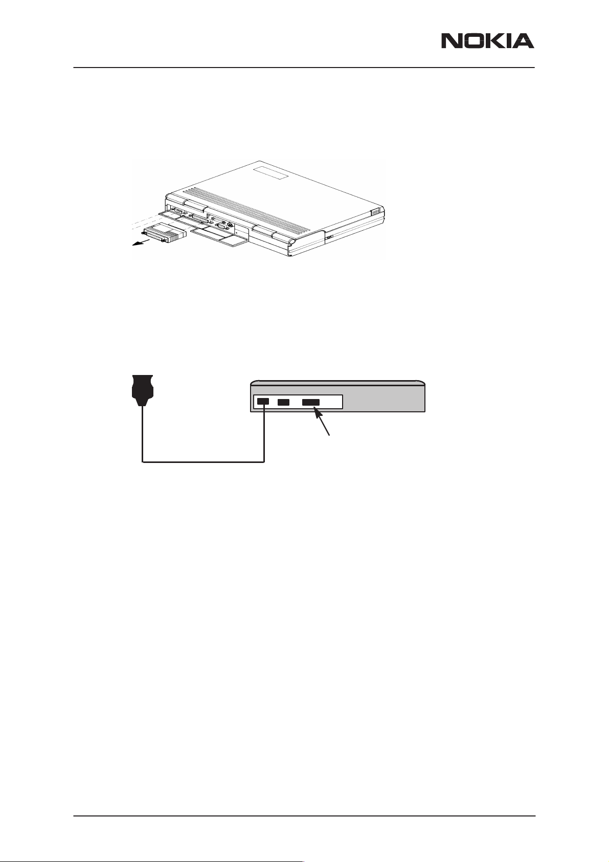
Mechanical Connections, Dealer Functions
The software controls the phone via a separate adapter (DAU–9P, or
DAU–9S) connected to the serial port of the PC and to the phone’s bottom connector using the Nokia proprietary communication method called
M2BUS.
Issue 1 06/1999
Nokia Mobile Phones Ltd.
Page 5
Page 6
NSD–3
Service Software and Tuning Instructions
Attach the protection key PKD–1* to parallel port one (25–pin female
D–connector) of the PC. When connecting the PKD–1 to the parallel port,
be sure that you insert the PC end of the PKD–1 to the PC (male side).
Dongle insertion
The PKD–1* should not affect devices working with it. If some errors do
occur, try printing without the PKD–1 connected. If printing is now OK
please contact your supplier who will endeavor to replace your PKD–1*.
PAMS Technical Documentation
DAU–9P
Servicing setup
COM1 COM2 LPT–1
PC
PKD–1
Page 6
Nokia Mobile Phones Ltd.
Issue 1 06/1999
Page 7

PAMS Technical Documentation
Service Software and Tuning Instructions
WinTesla Core Software Installation
The WinTesla core software is delivered on a 3.5” diskette and is protected with a protection “key” (PKD–1 or PKD–1D) which must be attached to the parallel port LPT1 when the WinTesla service software is
being used. Keep the original diskette safe to enable upgrading of the
program. To install the WinTesla software package, proceed as follows:
NOTE: For instructions on installing the service module (see Phone Specific Service Module Installation)
1. Insert the WinTesla Application diskette into your computer.
2. Start Windows, open File Manager, and log into drive A: Type A:
and press
3. Start INSTALL.EXE and install the WinTesla Core Software to
drive C:
After installing your Windows, desktop will now have a “Service Software”
group and a “Service Software” icon within that group.
<Enter>.
NSD–3
To start the program, double click on the “Service Software” icon.
NOTE: The dongle driver installation is mandatory for getting the Wintesla
SW to start. The dongle driver instruction is delivered with the dongle driver SW.
NOTE: If the case of using phone SW upgrading device (”Flash Box”) like
FLS–1 or FPS–4 the corresponding driver is needed to install before using the SW.
Issue 1 06/1999
Nokia Mobile Phones Ltd.
Page 7
Page 8

NSD–3
Service Software and Tuning Instructions
PAMS Technical Documentation
Phone Specific Service Module for NSD–1/3
Installation
The product specific DLL (Dynamic Link Library) is needed after the WinTesla Core software has been installed.
1. The floppy disk (product code: 0774102 in case of NSD–1/NSD–3)
includes NSD_w242.exe file, (where 242 is the version number, may be
different) double click it. The files will be loaded to the “temp” directory.
2. After this, use File Manager or My Computer and go to that
“temp” directory. Start/Run (or double click) the install.exe file. That will
install the phone specific program into your PC. The recommended file
structure is C:\wintesla\
3. The PC will show the status of the process.
Using WinTesla with NSD–1 and NSD–3 phones
The WinTesla application, “WinTesla.exe”, is phone independent. It relies
on separate, phone specific, “modules” to provide communication, menus
and test algorithms.
For each phone type – or product family – a phone interface module and
menu module are required. The modularity of WinTesla allows support for
other languages, so one phone type may have one phone interface module and several menu modules, all in different languages.
WinTesla allows you to select the language you wish to use (if available),
and will automatically load the correct phone interface module for the connected phone. When a different phone type is connected, WinTesla will
load the new phone interface and associated menus.
Menu Bar
The Service Software package will have two menu bar configurations.
The first, is an abbreviated version that contains the minimum number of
menus that allows package configurations when a phone is NOT connected. The second is described below:
The menu bar MUST only contain the following menus for the Service
Software package when a phone is connected:
Page 8
roduct*
• P
• C
onfigure*
uning (not available with PKD–1D)
• T
• Testing (not available with PKD–1D)
• Software
• Dealer
Nokia Mobile Phones Ltd.
Issue 1 06/1999
Page 9
PAMS Technical Documentation
• View
elp*
• H
* – always displayed, even if the phone is not connected.
The menu is broken down into sections that are indicated with menu sep-
arators. Each section identifies a logical difference from itself and other
sections, i.e. between transmitter and receiver. Any items that are required to be added to a menu lists will be added to the bottom of the appropriate menu section list. If a new item is to be added which is common
to two or more phone types, then that menu item will become a common
menu item.
The menu lists will use the Microsoft [...] symbol after an item name to indicate that selecting that item will NOT initiate an operation immediately.
A dialog box will be displayed for the user to select options or type in data
and press the OK button before the operation is performed.
NSD–3
Service Software and Tuning Instructions
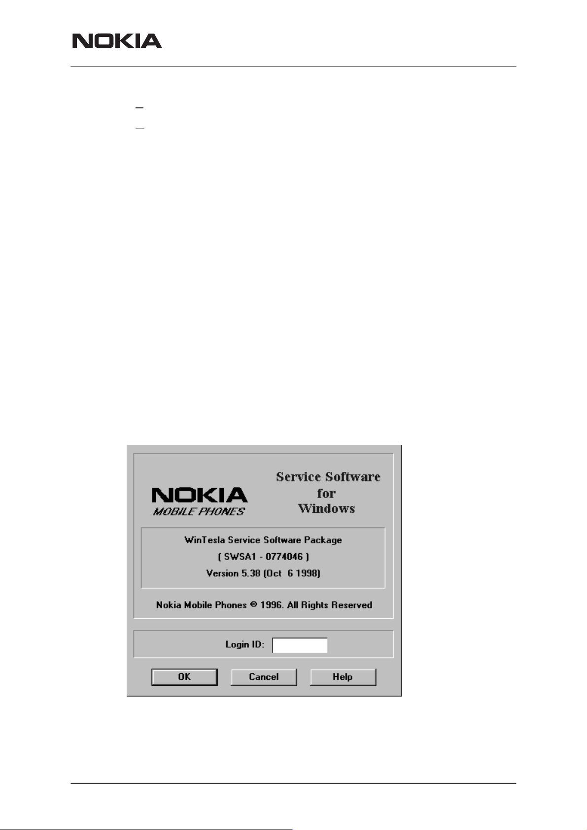
Login ID Setup (not needed for dealer use)
When WinTesla first starts, the Login screen below will appear. Type in
your 3 character ID and press <Enter> or click on the OK button.
Login Screen
If WinTesla cannot find the file, op_id.val, which contains the Login IDs,
then the OK button will be ‘grayed’. Otherwise, press the CANCEL button
and only the Fault Logging feature of WinTesla will be deactivated.
Issue 1 06/1999
Nokia Mobile Phones Ltd.
Page 9
Page 10
NSD–3
Service Software and Tuning Instructions
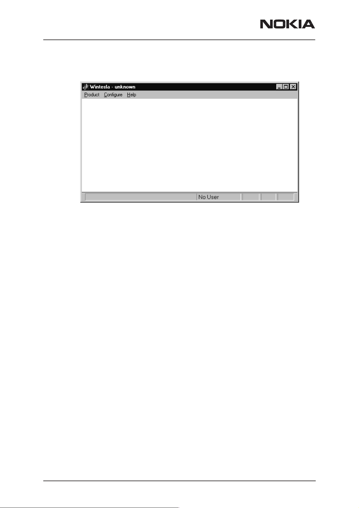
WinTesla Screen
PAMS Technical Documentation
The main WinTesla screen (if no phone is attached) is displayed with 3
menu items at the top of the screen and a status bar at the bottom.
The information on the left of the status bar will be used to provide information when WinTesla is performing tasks: such as reading data from
the phone. The status bar also includes the name of the current user.
Page 10
Nokia Mobile Phones Ltd.
Issue 1 06/1999
Page 11
PAMS Technical Documentation
Getting Started
Setup for BUS type and COM port:
When you have installed the WinTesla core software with PKD–1 drivers
and the product specific DLL software, the next step is to tell the software
what kind of hardware connection you are using.
NSD–3
Service Software and Tuning Instructions
1. Select the correct C
2. Select the H
(>>DAU for MBUS).
3. Select the M
4. Press A
When you start using the WinTesla program with a new phone you
should:
1. Select New, then the program starts to scan the phone that has been
connected to the PC or;
2. Select Open. Then you need to select the right product type, i.e.;
NSD–3.
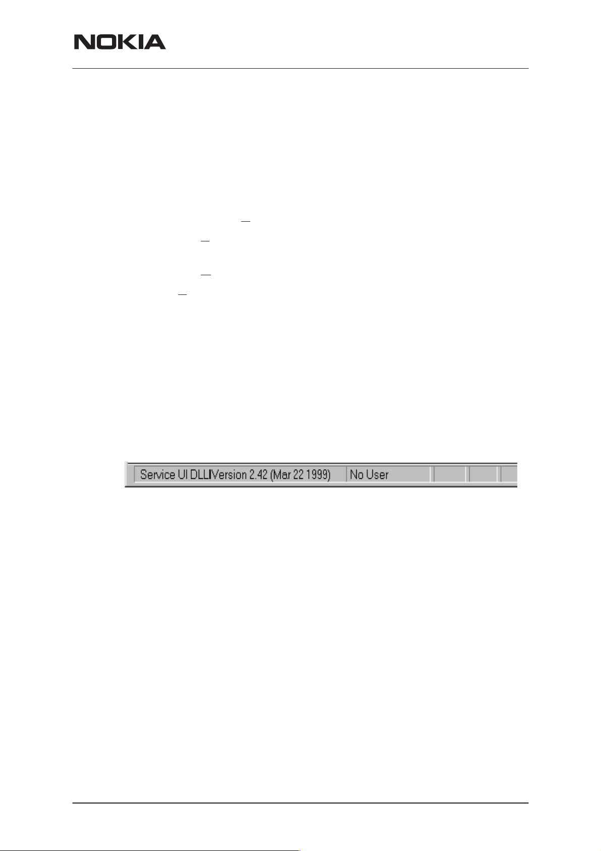
After the product specific DLL has been selected, it will be displayed on
the bottom of the PC screen. The version and date of the Product specific
DLL is also displayed.
ardware Type. For example, service cable DAU–9P
edia, For example, MBUS.
dd to save configuration.
OM Port. For example, COM1.
Issue 1 06/1999
Nokia Mobile Phones Ltd.
Page 11
Page 12
NSD–3
Service Software and Tuning Instructions
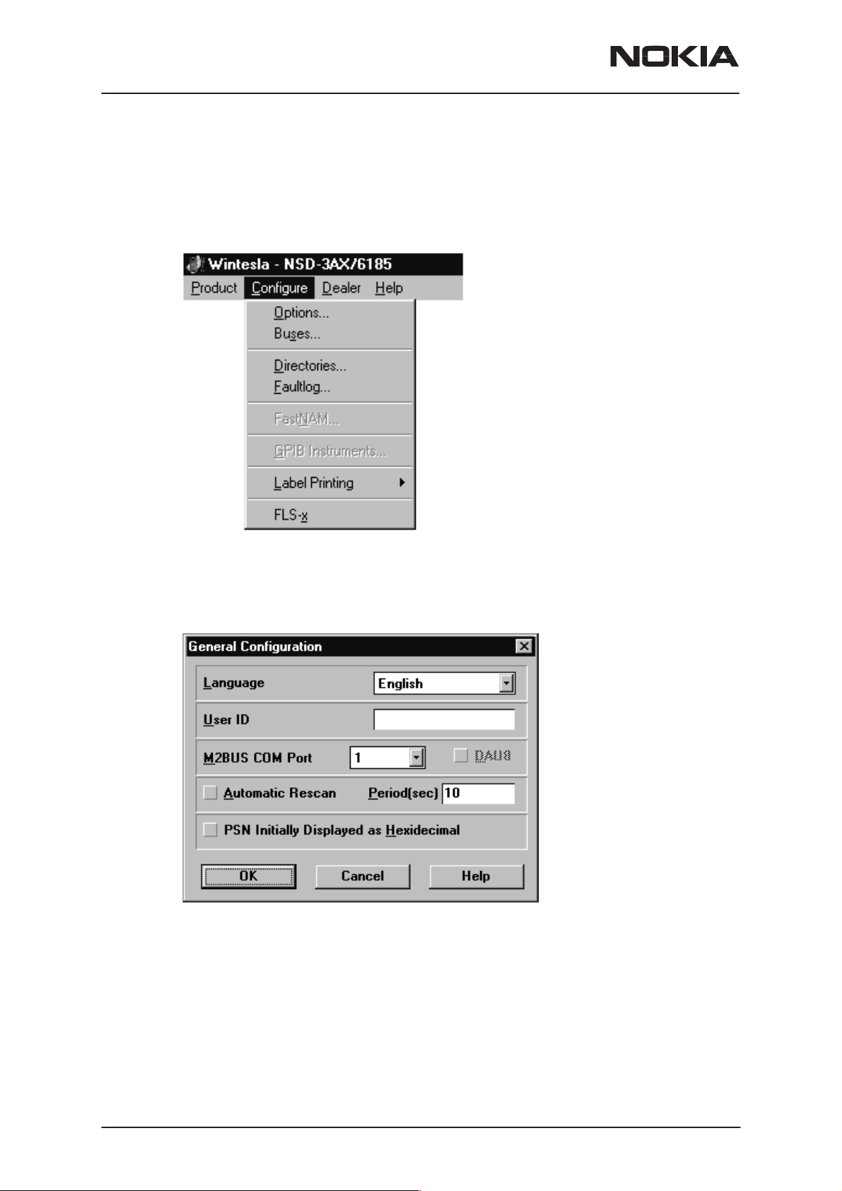
Configure Menu
The configuration menu allows you to setup such things as directory
paths, user interface language and FaultLog options.
PAMS Technical Documentation
Options
Language
This option allows you to change the language used in the WinTesla application.
Page 12
User ID
Allows the user ID to be entered if the user’s name is setup in the
opt_id.val (validation) file.
M2BUS COM Port
Nokia Mobile Phones Ltd.
Issue 1 06/1999
Page 13
PAMS Technical Documentation
This option allows you to select which communications port the phone is
to be connected. The change will take place immediately after pressing
OK.
Automatic Rescan
Automatic rescan is a mechanism to automatically check for the new
phone; the time between re–scans is user configurable. When a phone is
scanned and recognized, the corresponding phone interface and menu
are loaded, extending the main menu at the top of the screen and displaying the phone type and description at the bottom of the screen.
Product|New (or Ctrl+R ) function can be used to rescan the phone in–
The
between automatic rescans or when automatic rescan has been disabled.
The automatic re–scan mechanism is disabled when the
function is used to load a phone interface.
Check in the automatic rescan box enables the automatic rescan option.
Clicking on the check–box (making the check–box blank) will disable the
automatic re–scan option. The time between re–scans (in seconds) is entered into the edit box.
NSD–3
Service Software and Tuning Instructions
Product|Open
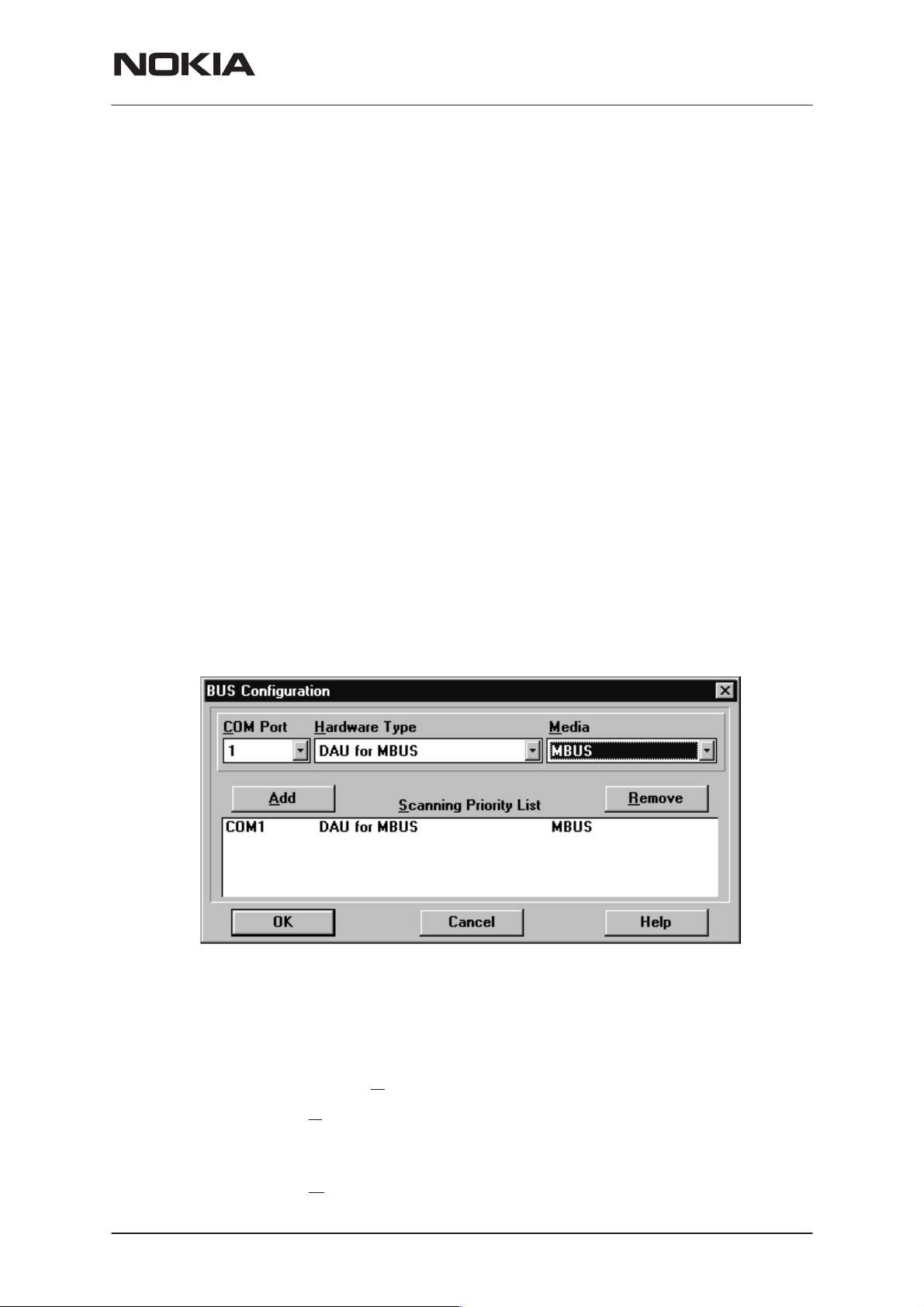
Buses
Pressing the OK button will save any changes made. Pressing CANCEL
will discard any changes you may have made.
Setup for BUS type and COM port:
When you have installed the WinTesla core software with PKD–1 drivers
and the product specific DLL software, the next step is to tell the software
what kind of hardware connection you are using.
1. Select the correct C
2. Select the Hardware Type. For example, service cable DAU–9P
(>>DAU for MBUS). In case of FLS–1 select also DAU for MBUS. IN case
of 3–box flash concept select Combox for MBUS.
3. Select the M
Issue 1 06/1999
OM Port. For example, COM1.
edia, For example, MBUS.
Nokia Mobile Phones Ltd.
Page 13
Page 14
NSD–3
Service Software and Tuning Instructions
4. Press Add to save configuration.
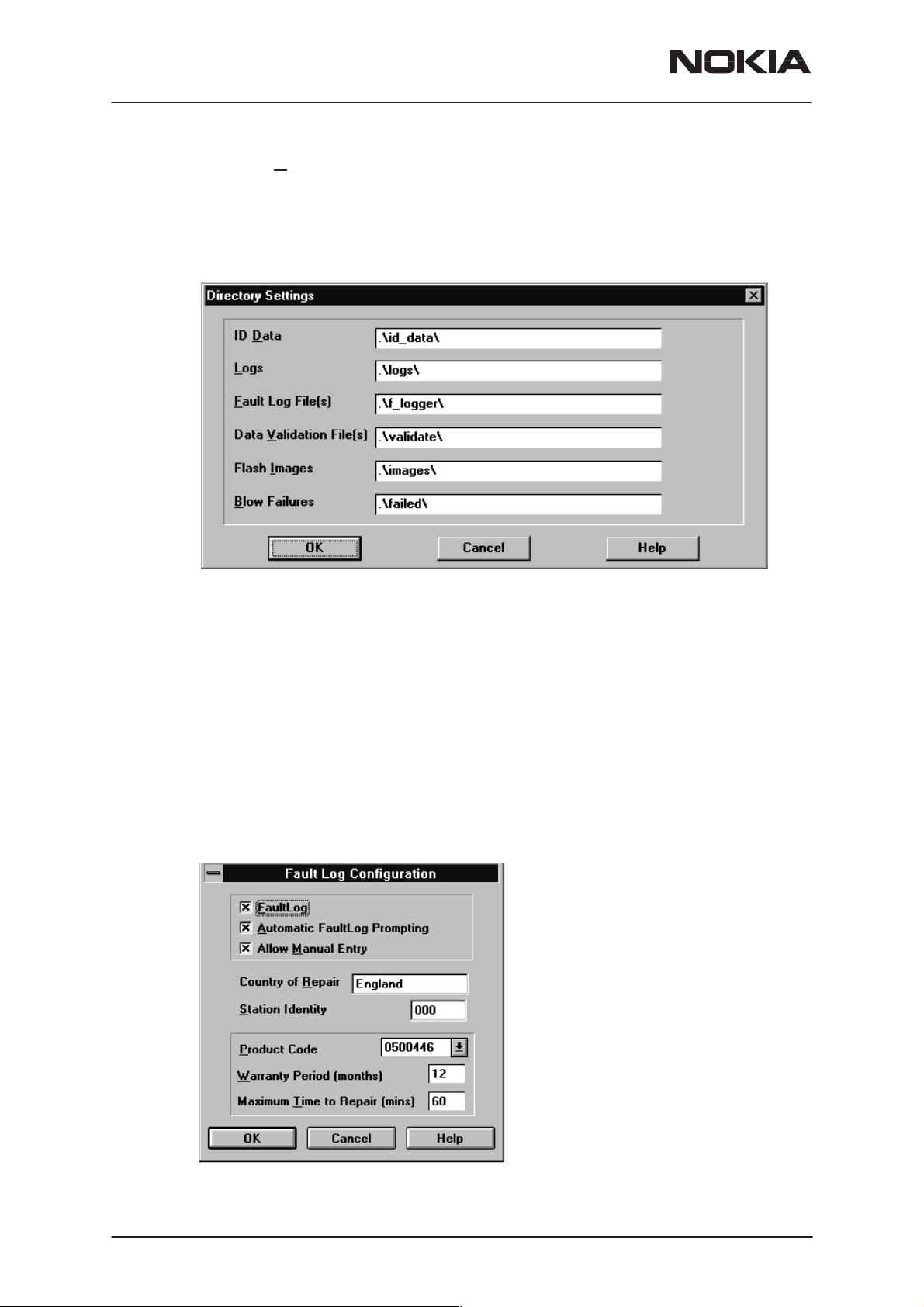
Directories
This function allows you to organize your data into different directories.
PAMS Technical Documentation
The directories already exist when the WinTesla core software is installed.
If an invalid directory is entered, then an error message will be displayed.
The use of a backslash (‘\’) at the end of the directory name is optional.
Clicking on the OK button will save your changes.
Fault Log Configuration (needed only if fault logger system in use)
Fault Log is a feature that allows the PC to create a record of each phone
that is serviced for historical tracking. This function allows you to configure the FaultLog mechanism. Clicking OK after making selections, saves
all changes made.
Page 14
Nokia Mobile Phones Ltd.
Issue 1 06/1999
Page 15

PAMS Technical Documentation
Fault Log
This option allows you to enable or disable the FaultLog mechanism.
Choosing to disable the FaultLog mechanism results in the
Log options being ‘greyed’ and the F9 button being disabled.
Allow Manual Entry
This option allows you to disable manual entry of data that was unavailable from the phone.
Automatic Fault Log Prompting
Enabling this option results in a prompt being displayed if the phone has
changed.
Station Identity
Enter the unique identity of your ‘workstation’; this ID is used to write
FaultLog files.
Country Of Repair
NSD–3
Service Software and Tuning Instructions
Product |Fault-
Enter the country of repair.
Warranty Period ( months )
Each product code has an associated warranty period. This option allows
you to change those warranty periods. If no phone is connected then all
product codes supported will be displayed. However, if a phone is connected then only the product codes associated with that phone type are
displayed.
Note: Changing the Warranty Period in the Fault Log data file has no affect on the products warranty terms as stated from the manufacturer.
Maximum Time To Repair ( minutes )
Enter the maximum time allowed to repair a phone.
Fault Log Application
The aim of the Fault Log application is to provide NMP After Sales Companies worldwide a standard method for the collection of Fault and Repair
Data from their service processes. This information can also be used by
NMP R&D and Manufacturing organizations as well.
The Fault Log application can be regarded as a data entry sub–routine
run from the WinTesla Service Software package at the end of a repair.
This allows for quick and uniform recording of the service performed on
the product.
Each product repaired, will generate one unique record in a FaultLog file
consisting of up to 37 data fields containing information about the product
and how it was repaired. This information is read automatically where
possible, from the products own internal EEPROM and then entered
manually by the Service Technician to form a complete service record.
For more advanced implementations, the repair records are copied and
collected by the electronic mail system installed in the Service Center and
are sent electronically to a Central Service Database located in Finland.
Issue 1 06/1999
Nokia Mobile Phones Ltd.
Page 15
Page 16

NSD–3
Service Software and Tuning Instructions
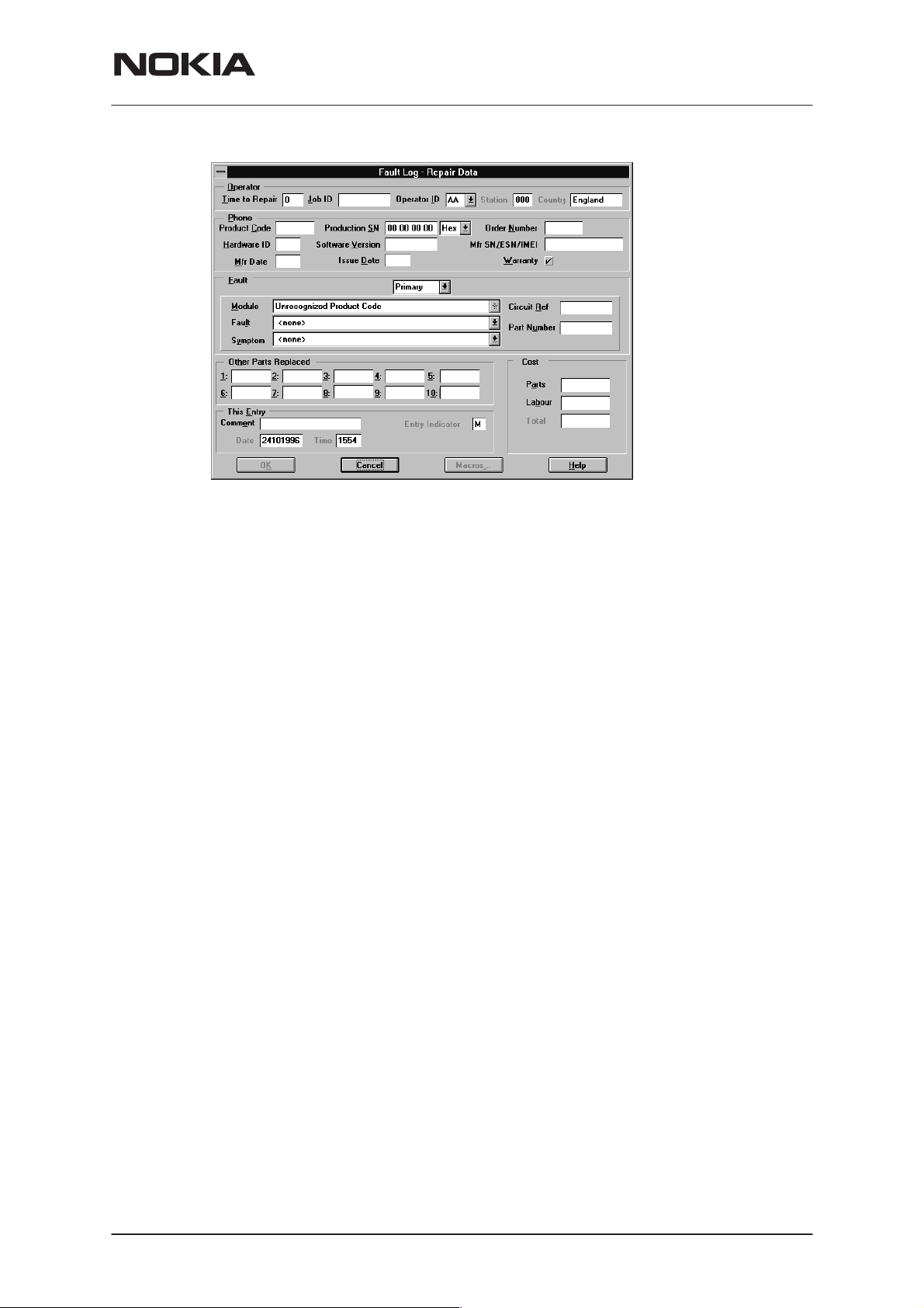
Completing a FaultLog Record
Once WinTesla has been configured correctly it operates in the following
manner:
– Wintesla automatically reads the product details from the products EEPROM and writes them as a record to a pre–determined file.
– Proceed with the repair task, utilising a combination of software driven
tuning and hardware modifications.
On completion of the repair task you have a choice:
A. With the product still connected to the PC, manually display
the repair data entry screen by selecting Function Button F9.
B. Alternatively, the product can be disconnected and the next
product for repair connected in its place.
As long as Automatic Prompting is enabled the previous products repair
data entry screen will be displayed.
PAMS Technical Documentation
Enter the repair work performed on the product in the repair
data screen.
Check the automatic data for this product, read earlier, to ensure its accuracy.
When satisfied with the data, save the entry. This process adds
a complete record containing the product details and the repair
details to the FaultLog output file.
The output file can then be manipulated by a number of different systems,
as required, as a detailed record of the product fault.
To attempt to record all of this information 37 data fields are defined for
each FaultLog record. These can be split as follows:
Product definition information fields
Repair / fault information fields.
Most products have their information stored in EEPROM. WinTesla automatically reads this information from the EEPROM and writes it to the
FaultLog record. This part of the record is shown below.
Most products have their information stored in EEPROM. WinTesla automatically reads this information from the EEPROM and writes it to the
FaultLog record. This part of the record is shown below.
Page 16
Nokia Mobile Phones Ltd.
Issue 1 06/1999
Page 17
PAMS Technical Documentation
NSD–3
Service Software and Tuning Instructions
Fields that are ‘greyed out’ etc. are data that has been automatically retrieved from the phone’s EEPROM. All other fields are entered manually;
fields are summarized below.
Operator
Automatic: Station, Country
Manual :
Phone
Automatic:
Manual:
Fault
Automatic: none
Manual
The current FaultLog application allows for the entering of three priority
levels of fault / repair information seen as
faults.
ry
Time to repair, Job ID, Operator ID
Product code, Production SN, Order No., Hardware
ID, Software version, Mfr. SN/ESN/IMEI, Mfr. Date,
Issue date
Warranty
Module, Fault, Symptom, Circuit ref., Part Number
Primary, Secondary
and
Tertia-
The
rows alongside each respective field.
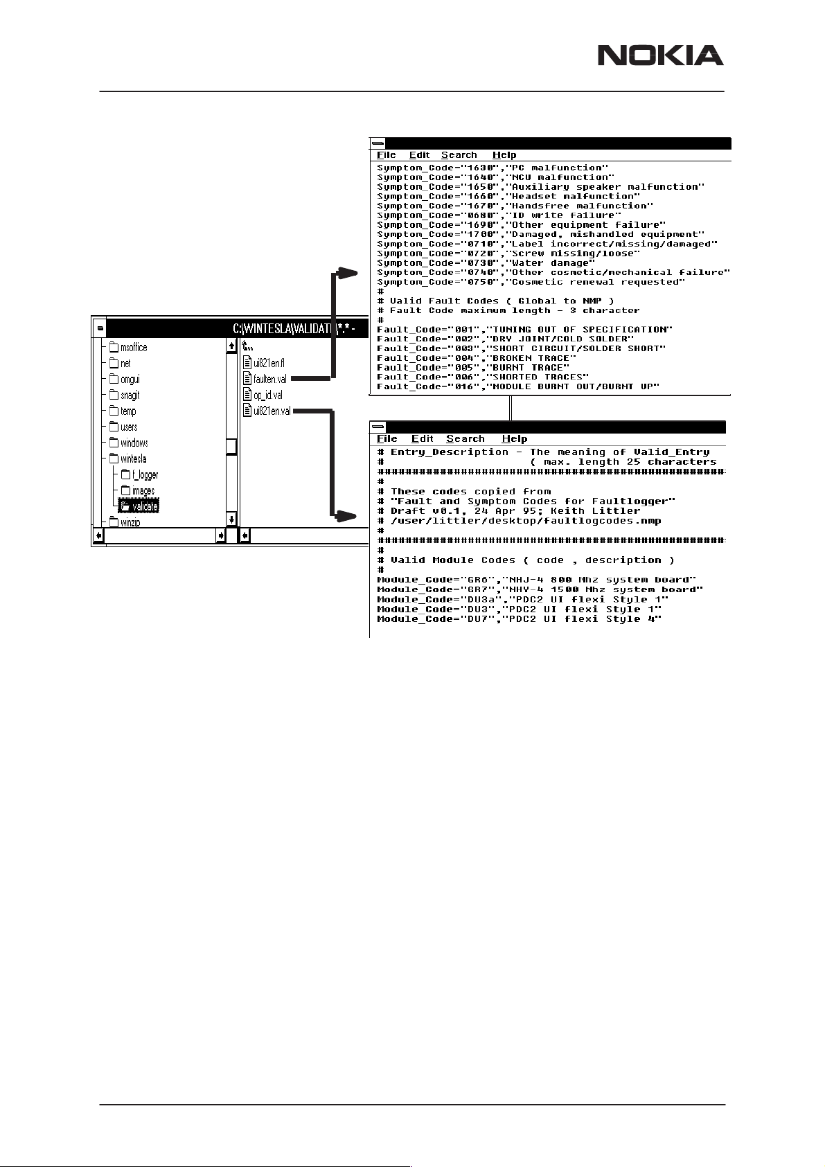
A comprehensive list of faults and symptoms as well as all current modules are already listed within the software. These three fields can be updated by accessing and editing the following files.
Field DOS File
Modules nhd4en.val
Faults, Symptoms faulten.val
Issue 1 06/1999
Module, Fault
and
Symptom
Nokia Mobile Phones Ltd.
fields have variables selected by the ar-
Page 17
Page 18
NSD–3
Service Software and Tuning Instructions
PAMS Technical Documentation
Notepad – FAULTEN.VAL
Notepad – UI821EN.VAL
Other Parts Replaced
Automatic none
Manual all fields
Enter other parts that have been replaced i.e. for wear and tear purposes
etc..
This Entry
Automatic Entry Indicator, Date, Time
Manual
Comment
Cost
Automatic Total
Manual
Parts, Labour
FaultLog Macros
The Macro sub–menu can be accessed by selecting the
macros button on
the FaultLog main screen.
Macro’s in FaultLog are a set of standard repair actions defined and
stored in order to represent frequently repeated repairs. These Macro’s
are related to the Product Code of the product, so whatever product is
Page 18
Nokia Mobile Phones Ltd.
Issue 1 06/1999
Page 19

PAMS Technical Documentation
connected, FaultLog will display the Macro list for that particular Product
Code.
A Macro’s standard repair information can also be pasted into the FaultLog record for that product.
Macro’s are saved initially under a name you can define yourself from the
main FaultLog screen. All the information contained in the manually entered fields i.e. Module, Fault, Symptom, Circuit Ref and Part Number are
recorded and saved under this name.
Flash Device…
This function is for select the right flash concept. The default setting is
POS flash with is based on FLS–1 device connected to the parallel port of
the PC.
If the FPS–4, FLA–5 and TDF–4 flash device is used then the setup
3–box is needed to select.
NSD–3
Service Software and Tuning Instructions
Issue 1 06/1999
Nokia Mobile Phones Ltd.
Page 19
Page 20
NSD–3
Service Software and Tuning Instructions
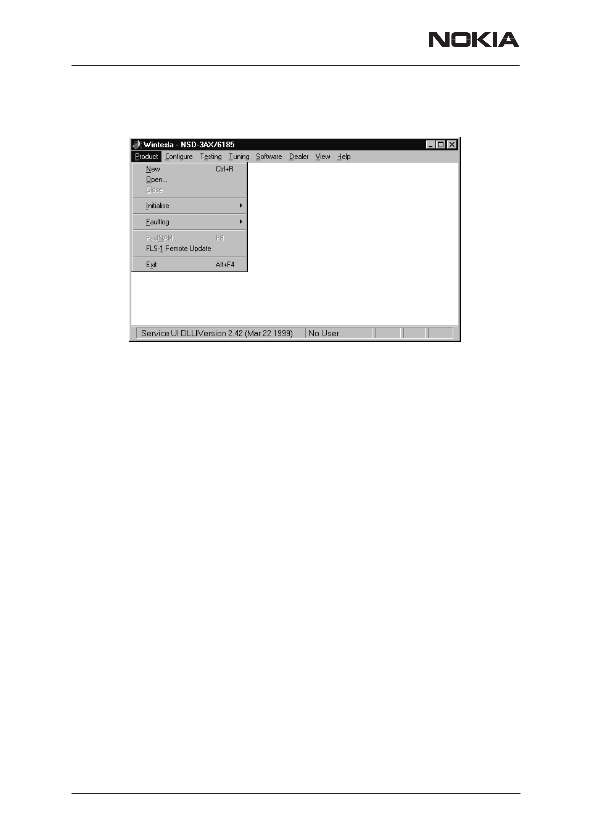
The Product Menu
PAMS Technical Documentation
New (Ctrl+R)
The ‘New’ function (which can also be activated by pressing Ctrl+R) is
used to scan for a phone when either the automatic rescan option is off or
the automatic rescan timer has not expired (see
for automatic rescan).
If the phone type is unrecognized or unsupported by the current WinTesla
system, then a warning message will be displayed.
If the phone is changed (with the same phone type only the serial number
is changed) the phone will be initialized into local mode. If the phone is
changed to a different phone type, the current DLLs are unloaded and
new ones are loaded for that phone.
If the Quick/RF Info view is open, the window will be automatically updated. If the Phone Information view is open, it will be automatically updated.
Open
The ‘Open’ function allows you to ‘force load’ a phone interface, even if
there is no phone connected to the system.
Configure|Options section
Page 20
Nokia Mobile Phones Ltd.
Issue 1 06/1999
Page 21
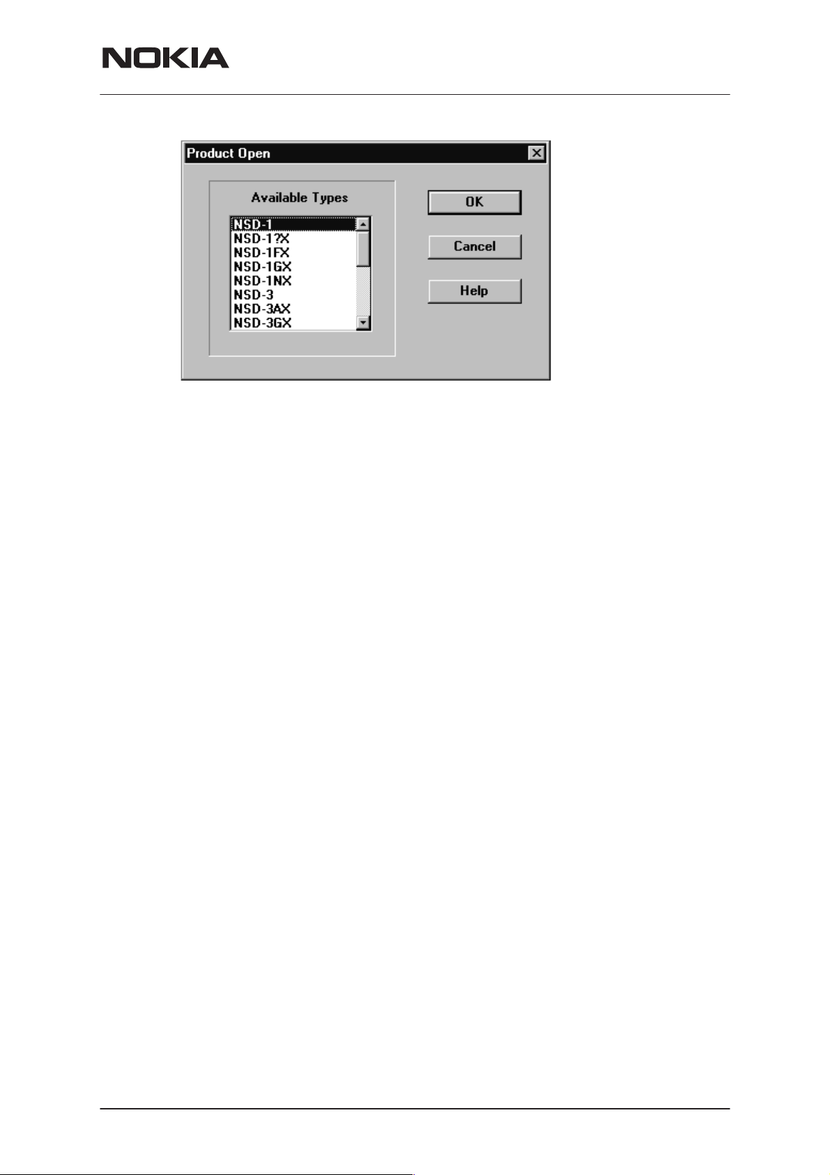
PAMS Technical Documentation
A dialog box will appear and a list of supported phone types. To select a
particular phone, highlight the phone type name and click OK.
Clicking on CANCEL will stop the request and no new phone type will be
loaded.
NSD–3
Service Software and Tuning Instructions
Close
Initialize
Loading a phone interface will disable the automatic rescan function (see
Configure|Options section for automatic rescan).
This function will close the currently loaded phone type interface that had
been loaded using the Configure|Options function. You cannot ‘Close’ a
loaded phone type interface if it was loaded by a rescan.
Activation Status Bar Text
Alt, P, I Opens a submenu for the Normal Mode and the Lo-
cal Mode.
Normal Mode
Activation Status Bar Text
Alt, P, N Initializes the phone to normal (cellular) mode
F5
When the normal mode has been activated or the program has been
started, self–test results will be asked from the MCU. If any fault was
found in the tests, an error message is shown. If the normal mode has
been set successfully (no self–test error has been found), and paging listening has been started, the used AFC value is requested from MS.
Initialization routine checks the phones’ cellular type and if it is unsupported, the phone application unloads the DLLs.
The After Sales SW sets automatically the MS state to normal mode
when needed.
Issue 1 06/1999
Nokia Mobile Phones Ltd.
Page 21
Page 22

NSD–3
Service Software and Tuning Instructions
If phone identification view is open, window will be automatically updated.
Also if RF Information Window is open it will be updated to quick info
view.
Local Mode
Activation Status Bar Text
Alt, P, L Initializes phone to local mode
Shift + F5
PAMS Technical Documentation
Selection will change the MS state to
from Testing or Tuning menus, the After Sales SW software will change
automatically the MS state to local.
The After Sales SW sets automatically the MS state to normal mode
when needed.
Also if quick info view is open it will be updated to RF Information view.
FaultLog
Exit (Alt+F4)
Selecting this option will shutdown the WinTesla program.
local
. When the user selects item
Activate Faultlog…
E
dit Faultlog…
This function is only needed if fault logger system is in use.
Page 22
Nokia Mobile Phones Ltd.
Issue 1 06/1999
Page 23
PAMS Technical Documentation
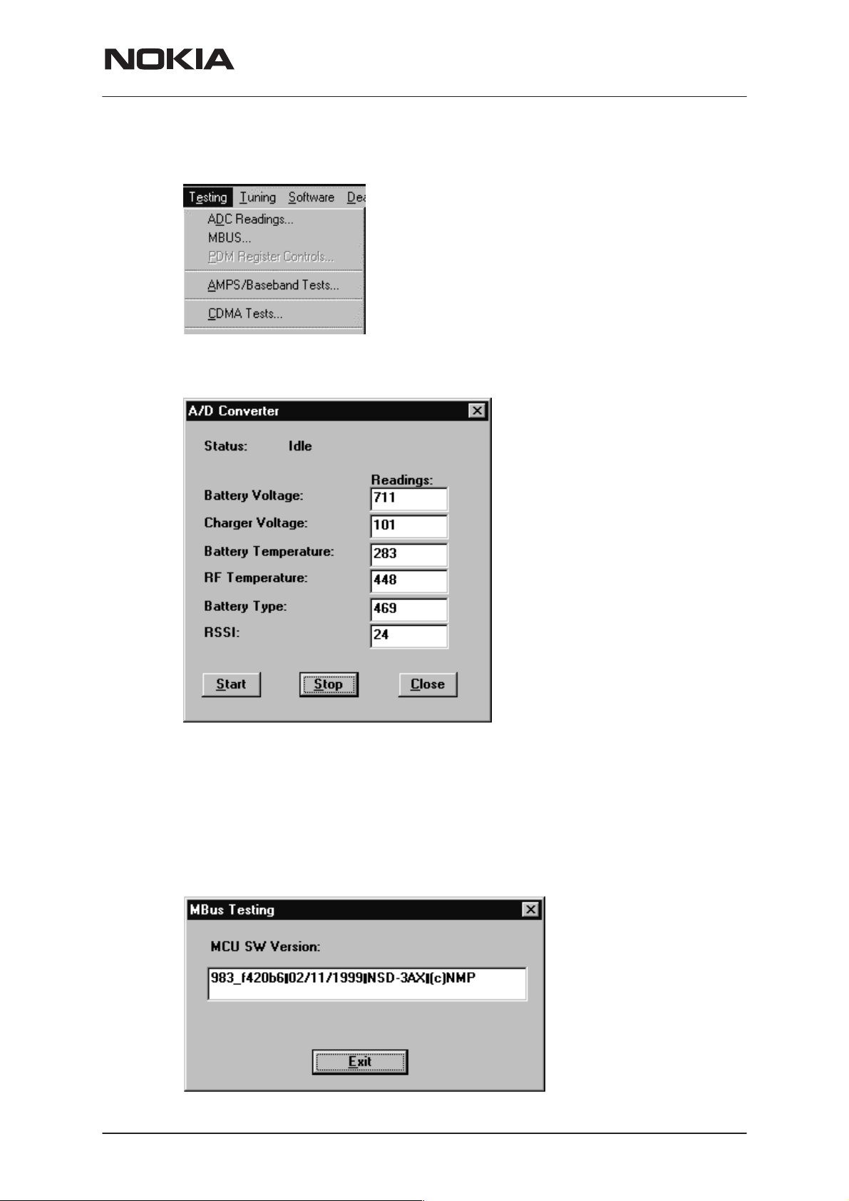
The Testing Menu
ADC Readings
NSD–3
Service Software and Tuning Instructions
This option allows the phone’s ADC readings to be displayed. The readings are updated every few seconds. There may be some delay before
the mouse or keyboard responds while running this test.
MBUS
Mbus displays the MCU software version.
Issue 1 06/1999
Nokia Mobile Phones Ltd.
Page 23
Page 24

NSD–3
Service Software and Tuning Instructions
AMPS / Base Band Tests
This screen is used when testing and troubleshooting the phone in AMPS
mode. Below is an example screen.
PAMS Technical Documentation
Page 24
RF Controls:
Power Level – Turns the transmitter on/off and sets power levels.
Channel – Changes the AMPS channel of the phone.
TX Freq: Displays the current Transmit Frequency.
RX Freq: Displays the current Receiver Frequency.
Frequency:
High – Sets the AMPS channel to the Highest Frequency according to
the Frequency planning set in the “configure” menu.
Mid – Sets the AMPS channel to the Middle Frequency according to the
Frequency planning set in the “configure” menu.
Low – Sets the AMPS channel to the Lowest Frequency according to the
Frequency planning set in the “configure” menu.
Channel:
Nokia Mobile Phones Ltd.
Issue 1 06/1999
Page 25

PAMS Technical Documentation
Up – Increments the channel selection by one.
Dn – Decrements the channel selection by one.
Tone Controls:
Allows computer control of Supervisory Audio Tone (SAT), buzzer, Signaling Tone (ST), and vibrating functions.
Audio Paths:
TX Path: – Allows the user to control the TX Audio path (options: Mute,
Ear, External Ear).
RX Path: – Allows the user to control the Rx Audio path (options: Mute,
Ear, External Ear).
Miscellaneous Controls:
Allows control of LCD patterns, call LED and back light.
Buttons:
NSD–3
Service Software and Tuning Instructions
ADC Reading
Opens the ADC reading screen.
Mbus Test
Tests the communication between the phone and the computer.
Phone Identity
Opens the Quick Receiver test screen.
RF Parameter
This function allows read the saved RF parameters (tuning values) from
the phone.
Reset Phone
Resets the phone.
Init Phone
Initializes the phone.
Close
Exits the current screen.
CDMA Tests
This screen is used when testing and troubleshooting the phone in CDMA
mode. Below is an example screen.
Issue 1 06/1999
Nokia Mobile Phones Ltd.
Page 25
Page 26

NSD–3
Service Software and Tuning Instructions
PAMS Technical Documentation
ADC Readings
This option allows the phone’s ADC readings to be displayed. The readings are updated every few seconds. There may be some delay before
the mouse or keyboard responds while running this test.
Page 26
Nokia Mobile Phones Ltd.
Issue 1 06/1999
Page 27

PAMS Technical Documentation
The Tuning Menu
NSD–3
Service Software and Tuning Instructions
Tuning Steps of Radio Unit
The Service Software program places the phone into the Local mode, in
which the phone can be outwardly controlled via M2BUS interface.
The tuning values of the phone reside on the EEPROM. Before tuning,
the Service Software reads these values and the user can change these
values with tuning functions.
NOTE: During tuning, keep the following in mind:
– Take care not to damage sensitive measuring instruments with exces-
sive RF power.
– Carry out all tuning steps in the shortest possible time to avoid exces-
sive heating of RF units.
– Perform all tuning steps in the order presented.
– Never try to mask a fault by tuning it out.
Accuracy of the Equipment during Measurement
– Power supply 1; nominal voltage 8.0V ±0.2V , minimum current capacity
1.5A for service battery BBD–3.
– Power Supply 2; nominal voltage 4.1 ±0.1V, minimum current capacity
1.5A for testing dummy battery BTD–3.
– Modulation analyzer; power level resolution 0.1dB, accuracy ±0.5dB.
Frequency counter accuracy 0.1ppm (±80Hz).
Issue 1 06/1999
Nokia Mobile Phones Ltd.
Page 27
Page 28

NSD–3
Service Software and Tuning Instructions
– RF generator; frequency resolution 10Hz amplitude resolution 0.1dB
frequency stabilization ±0.25ppm.
– Spectrum analyzer; dynamic range 70dB, accuracy ±1dB (For power
level measurement accuracy ±0.5dB).
Battery Tuning
PAMS Technical Documentation
Battery Voltage Tuning:
A reference value for the battery is calibrated by using BDD–3 service
battery.
NOTE:
Calibration of the A/D converter channels as follows:
– Connect the cable SCB–3 from service battery to the charging connec-
tor. Apply +10.5V to the service battery.
– Select “Tuning > Battery > Tuning Battery.
– Select ”Tune”
– The Program reads the voltage and current and displays the corre-
sponding A/D reading fed to the phone via the VBATT line.
– Store this new value to the phone by pressing “Tune”. Then “Save &
Exit”.
Page 28
Nokia Mobile Phones Ltd.
Issue 1 06/1999
Page 29

PAMS Technical Documentation
Service Software and Tuning Instructions
Charging Voltage and Current Tuning:
A reference value for the battery is calibrated by using BDD–3 service
battery.
NSD–3
Calibration of the A/D converter channels as follows:
– Connect the cable SCB–3 from service battery to the charging connec-
tor. Apply +10.5V to the service battery.
– Select: Tuning > Battery> Tuning Charge”.
– The Program reads the voltage and current and displays the corre-
sponding A/D reading fed to the phone via the VBATT line.
– Store this new value to the phone by pressing “Tune”. Then “Save &
Exit”.
AMPS Tunings.
Not available for NSD–1F phone.
Issue 1 06/1999
Nokia Mobile Phones Ltd.
Page 29
Page 30

NSD–3
Service Software and Tuning Instructions
AFC (Automatic Frequency Control).
Spectrum Analyzer set up:
PAMS Technical Documentation
Set up spectrum analyzer as follows:
Center frequency Frequency in tuning window
Span 20 KHz
Amplitude Reference level 30 dBm
Attenuation Auto
Amplitude level offset 0 dB
Resolution bandwidth (RBW) Auto
Video bandwidth (VBW) Auto
Sweep time Auto
Marker track On
Connect Spectrum Analyzer to phone’s antenna connector.
Press PEAK SEARCH button if marker is not on signal’s peak.
Tune using Up, Dn, PgUp and pgDn buttons until marker frequency is
within target range.
Page 30
Nokia Mobile Phones Ltd.
Issue 1 06/1999
Page 31

PAMS Technical Documentation
Tx Power Level
NSD–3
Service Software and Tuning Instructions
Note: The default cable loss 0.7 dB is taken into account in the values. If
some other cables are used please, input the new value by using frequency planning.
Note: The channel needs to be between550–580.
AMPS Tuning––TX POWER LEVEL:
Set up spectrum analyzer as follows:
Center frequency Use channel 550–580
Span 20 KHz
Amplitude Reference level 30 dBm
Attenuation Auto
Amplitude level offset 0 dB
Resolution bandwidth (RBW) Auto
Video bandwidth (VBW) Auto
Sweep time Auto
Marker track On
Connect Spectrum Analyzer to phone’s antenna connector.
Press PEAK SEARCH button if marker is not on signal’s peak.
Select power level to be tuned.
Tune using Up, Dn, PgUp and pgDn buttons until marker power is within
target range.
Issue 1 06/1999
Nokia Mobile Phones Ltd.
Page 31
Page 32

NSD–3
Service Software and Tuning Instructions
Tx Modulation Index
PAMS Technical Documentation
AMPS Tuning––TX MODULATION INDEX:
Set up communication analyzer (HP8924, HP8920 etc) as follows:
Select DUPLEX under Analog Screen.
Channel Channel number in tuning window
IF filter 15KHz
AF Anl in FM Demod
Filter 1 300Hz HPF
Filter 2 6KHz BPF
De_amphasis ON
Detector +/– Max
Connect communication analyzer ’s output to phone’s antenna connector.
Tune using Up, Dn, PgUp and PgDn buttons until frequency deviation is
within target range.
RSSI (Received Signal Strength Indication)
Page 32
Nokia Mobile Phones Ltd.
Issue 1 06/1999
Page 33

PAMS Technical Documentation
AMPS Tuning–RSSI Step 1
Set up communication analyzer (HP8924, HP8920 etc) as follows:
Select DUPLEX under Analog Screen.
Level offset Off
Channel Channel number in tuning window
Amplitude Level in tuning window
Audio freq 1KHz
AF Anl out FM
Freq. Deviation2.6KHz
Connect communication analyzer ’s output to phone’s antenna connector
Step 1. Press TUNE button. Press NEXT button to go to Step 2.
Step 2. Set communication analyzer output amplitude to new level.
NSD–3
Service Software and Tuning Instructions
Press TUNE button. The tuning value should be between 570…970.
AMPS Tuning–RSSI Step 2
Set up communication analyzer (HP8924, HP8920 etc) as follows:
Select DUPLEX under Analog Screen.
Level offset Off
Channel Channel number in tuning window
Amplitude Level in tuning window
Audio freq. 1KHz
AF Anl out FM
Freq. Deviation 2.6KHz
Connect communication analyzer ’s output to phone’s antenna connector
Step 1. Press TUNE button. Press NEXT button to go to Step 2.
Step 2. Set communication analyzer output amplitude to new level.
Press TUNE button. The tuning value should be between 750…1050.
Issue 1 06/1999
Nokia Mobile Phones Ltd.
Page 33
Page 34

NSD–3
Service Software and Tuning Instructions
Rx Audio Gain
PAMS Technical Documentation
AMPS Tuning––RX AUDIO GAIN
Set up communication analyzer (HP8924, HP8920 etc) as follows:
Select DUPLEX under Analog Screen
Level offset Off
Channel Channel number in tuning window
Amplitude Level –50 dBm
Audio freq 1KHz
AF Anl out FM
Freq. Deviation 2.6KHz
AF Anl in Audio in
Filter1 C Message
Filter2 3 KHz LPF
De_amphasis OFF
Detector +/– Max
– Connect communication analyzer’s output to phone’s antenna connec-
tor.
Page 34
– Connect phone’s external EAR to communication analyzer’s AUDIO IN.
– Tune using Up, Dn, PgUp and PgDn buttons until AF level is within tar-
get range.
Nokia Mobile Phones Ltd.
Issue 1 06/1999
Page 35

PAMS Technical Documentation
800 CDMA Tunings.
Not available for NSD–1F phone.
NSD–3
Service Software and Tuning Instructions
TX IF AGC
CELL TUNING––TX_IF_AGC
Point 1:
Set up spectrum analyzer as follows:
Center frequency Frequency in tuning window
Span 30 MHz
Amplitude Reference level 10 dBm
Attenuation Auto
Amplitude level offset 0 dB
Resolution bandwidth (RBW) 1 MHz
Video bandwidth (VBW) 300 Hz
Issue 1 06/1999
Nokia Mobile Phones Ltd.
Page 35
Page 36

NSD–3
Service Software and Tuning Instructions
Sweep time Auto
Marker track On
Connect Spectrum Analyzer to phone’s antenna connector.
Press PEAK SEARCH button if marker is not on signal’s peak.
Tune using Up, Dn, PgUp and PgDn buttons until marker power is within
target range.
Point 2:
Keep spectrum analyzer setup unchanged.
Tune using Up, Dn, PgUp and PgDn buttons until marker power is within
target range.
TX_LIM_ADJ tuning:
Make following change to spectrum analyzer setup:
Amplitude Reference Level : 30 dBm
PAMS Technical Documentation
For each new frequency, press PEAK SEARCH button if marker is not on
signal’s peak.
Tune using Up, Dn, PgUp and pgDn buttons until marker power is within
target range.
LNA Switch
CELL TUNING––LNA GAIN SWITCH
Page 36
Set up communication analyzer as follows:
Select DUPLEX under Analog Screen.
Select FREQUENCY in RF DISPLAY under CONFIG.
Level offset Off
Generator frequency Frequency in tuning window
Amplitude Level in tuning window
Connect communication analyzer ’s output to phone’s antenna connector.
Nokia Mobile Phones Ltd.
Issue 1 06/1999
Page 37

PAMS Technical Documentation
Press TUNE button to tune.
RX IF AGC
NSD–3
Service Software and Tuning Instructions
CELL TUNING–RX IF AGC
Steps 1,2,3…
Set up communication analyzer as follows:
Select DUPLEX under Analog Screen.
Select FREQUENCY in RF DISPLAY under CONFIG.
Level offset Off
Generator frequency Frequency in tuning window
Amplitude Level in tuning window
Connect communication analyzer ’s output to phone’s antenna connector.
Press TUNE button to tune.
Press NEXT button to go to next step. Repeat process with different am-
plitudes.
TX IF AGC
Issue 1 06/1999
Nokia Mobile Phones Ltd.
Page 37
Page 38

NSD–3
Service Software and Tuning Instructions
CELL TUNING––TX_IF_AGC
Point 1:
Set up spectrum analyzer as follows:
Center frequency Frequency in tuning window
Span 30 MHz
Amplitude Reference level 10 dBm
Attenuation Auto
Amplitude level offset 0 dB
Resolution bandwidth (RBW) 1 MHz
Video bandwidth (VBW) : 300 Hz
Sweep time Auto
Marker track On
PAMS Technical Documentation
Connect Spectrum Analyzer to phone’s antenna connector.
Press PEAK SEARCH button if marker is not on signal’s peak.
Tune using Up, Dn, PgUp and pgDn buttons until marker power is within
target range.
Point 2:
Keep spectrum analyzer setup unchanged.
Tune using Up, Dn, PgUp and pgDn buttons until marker power is within
target range.
TX_LIM_ADJ tuning:
Make following change to spectrum analyzer setup:
Amplitude Reference Level: 30 dBm
For each new frequency, press PEAK SEARCH button if marker is not on
signal’s peak.
Tune using Up, Dn, PgUp and pgDn buttons until marker power is within
target range.
Page 38
Nokia Mobile Phones Ltd.
Issue 1 06/1999
Page 39

PAMS Technical Documentation
LNA Switch
CELL TUNING––LNA GAIN SWITCH
Set up communication analyzer as follows:
NSD–3
Service Software and Tuning Instructions
Select DUPLEX under Analog Screen.
Select FREQUENCY in RF DISPLAY under CONFIG.
Level offset Off
Generator frequency Frequency in tuning window
Amplitude Level in tuning window
Connect communication analyzer ’s output to phone’s antenna connector.
Press TUNE button to tune.
RX IF AGC
CELL TUNING–RX IF AGC
Steps 1,2,3…
Set up communication analyzer as follows:
Issue 1 06/1999
Nokia Mobile Phones Ltd.
Page 39
Page 40

NSD–3
Service Software and Tuning Instructions
Select DUPLEX under Analog Screen.
Select FREQUENCY in RF DISPLAY under CONFIG.
Level offset Off
Generator frequency Frequency in tuning window
Amplitude Level in tuning window
–Connect communication analyzer ’s output to phone’s antenna connec-
tor.
–Press TUNE button to tune.
–Press NEXT button to go to next step. Repeat process with different
amplitudes.
RX IF Compensation
PAMS Technical Documentation
Page 40
CELL TUNING––RX_IF FREQ COMPENSATION
Set up communication analyzer as follows:
Select DUPLEX under Analog Screen.
Select FREQUENCY in RF DISPLAY under CONFIG.
Level offset Off
Generator frequency Frequency in tuning window
Amplitude Level in tuning window
– Connect communication analyzer’s output to phone’s antenna connec-
tor.
– Press TUNE button to tune.
– Press NEXT button to go to next step. Repeat process with different fre-
quencies.
Nokia Mobile Phones Ltd.
Issue 1 06/1999
Page 41

PAMS Technical Documentation
1900 MHz CDMA Tunings.
Not available for NSD–1/3G phones.
NSD–3
Service Software and Tuning Instructions
Note: For NSD–1F phone the AFC tuning needs to be done at 1900MHz.
Tx IF AGC (1900MHz)
PCS TUNING––TX_IF_AGC
Point 1:
Set up spectrum analyzer as follows:
Center frequency Frequency in tuning window
Span 65 MHz
Amplitude Reference level 10 dBm
Attenuation Auto
Amplitude level offset 0 dB
Resolution bandwidth (RBW) 1 MHz
Issue 1 06/1999
Nokia Mobile Phones Ltd.
Page 41
Page 42

NSD–3
Service Software and Tuning Instructions
Video bandwidth (VBW) 300 Hz
Sweep time Auto
Marker track On
– Connect Spectrum Analyzer to phone’s antenna connector.
– Press PEAK SEARCH button if marker is not on signal’s peak.
– Tune using Up, Dn, PgUp and pgDn buttons until marker power is within
target range.
Point 2:
– Keep spectrum analyzer setup unchanged.
– Tune using Up, Dn, PgUp and pgDn buttons until marker power is within
target range.
PAMS Technical Documentation
Tuning Max Power, TX_LIM_ADJ tuning: (1900)
Page 42
TX_LIM_ADJ tuning:
Make following change to spectrum analyzer setup:
– Amplitude Reference level 30 dBm
– For each new frequency, press PEAK SEARCH button if marker is not
on signal’s peak.
– Tune using Up, Dn, PgUp and PgDn buttons until marker power is with-
in target range.
Nokia Mobile Phones Ltd.
Issue 1 06/1999
Page 43

PAMS Technical Documentation
LNA GAIN SWITCH (1900MHz)
PCS TUNING––LNA GAIN SWITCH
NSD–3
Service Software and Tuning Instructions
Set up communication analyzer as follows:
Select DUPLEX under Analog Screen.
Select FREQUENCY in RF DISPLAY under CONFIG.
Level offset Off
Generator frequency Frequency in tuning window
Amplitude Level in tuning window
– Connect communication analyzer’s output to phone’s antenna connec-
tor.
– Press TUNE button to tune.
RX IF AGC (1900MHz)
PCS TUNING–RX IF AGC
Issue 1 06/1999
Nokia Mobile Phones Ltd.
Page 43
Page 44

NSD–3
Service Software and Tuning Instructions
Set up communication analyzer as follows:
Select DUPLEX under Analog Screen.
Select FREQUENCY in RF DISPLAY under CONFIG.
Level offset Off
Generator frequency Frequency in tuning window
Amplitude Level in tuning window
– Connect communication analyzer’s output to phone’s antenna connec-
tor.
– Press TUNE button to tune. Press NEXT button to go to next step.
Repeat process with different amplitudes.
Rx If Compensation (1900MHz)
PAMS Technical Documentation
RX_IF FREQ COMPENSATION
Set up communication analyzer as follows:
Select DUPLEX under Analog Screen.
Select FREQUENCY in RF DISPLAY under CONFIG.
Level offset Off
Generator frequency Frequency in tuning window
Amplitude Level in tuning window
– Connect communication analyzer’s output to phone’s antenna connec-
tor.
– Press TUNE button to tune.
– Press NEXT button to go to next step. Repeat process with different
frequencies
Factory Values
This function makes possible save the factory default tuning values to the
phone. This function is needed only if the all tuning values have been lost.
After this all the tuning are needed to do manually.
Page 44
Nokia Mobile Phones Ltd.
Issue 1 06/1999
Page 45

PAMS Technical Documentation
The Software Menu
This command is used for flashing new software into the phone. While
flashing the phone, user is shown the flashing progress towards completion.
Status dialog box is shown during flashing. After the phone is flashed Authority ID is set to the phone.
NSD–3
Service Software and Tuning Instructions
Flash File Programming
The Flash Phone dialog box contains the following items:
Save User Data:
This option decides if user data (end user settings) will be kept.
Yes The user data will be saved (recommended).
No Select if there is no need to save user data (new phone).
Advanced Options Select only in special cases.
Issue 1 06/1999
Nokia Mobile Phones Ltd.
Page 45
Page 46

NSD–3
Service Software and Tuning Instructions
BUTTONS:
Auto File Select
Wintesla will find a correct image for a connected phone according to its
hardware ID and product code.
Browse
Click this button to select a flash image.
Read Ver
Displays software version of the phone.
Clear/Stop
Clear the flash window. Stops saving user data during flashing.
Flash/Restore
Flashing a software into the phone or restore data to a phone.
Authority ID
PAMS Technical Documentation
Programs the authority ID. By default Authority ID is programmed automatically after flashing. There is no need to do it manually.
Close button
Closes the dialog button and
Procedure to Flash a Phone
1. Decide Which Options to use
There are 3 options, Yes, No and Advanced options. Yes will keep all the
user data. No will erase all user data. Advanced option let you decide
what kind of data you want to keep during flash.
2. Select Flash image (or let Wintesla decide for you)
You can select a flash file by clicking the Browse button. Or you can leave
the file name field empty and let Wintesla decide which flash image to
use. Please note this requires a phone specific .cfg file be put into .../misc
directory.
3. Flash
FAQs:
does not
start flashing.
Page 46
How to select flashing device?
Go Configure Menu/FLS–X and check Use Fls–x for POS, otherwise un-
check it
If the phone is totally dead. Go to the Advanced Options and select Flash
Dead Phone then flash the phone.
What if error occurs during the user data saving?
No damage is done to your phone at this stage. So go ahead and flash it
again.
Nokia Mobile Phones Ltd.
Issue 1 06/1999
Page 47

PAMS Technical Documentation
What if error occurs during flashing?
If the phone is dead, go to the Advanced Options and select Flash Dead
Phone and flash the phone again. EEPROM values shouldn’t be damaged at this stage. If the phone isn’t dead, EEPROM values shouldn’t be
changed yet. Just flash the phone again.
What if error occurs after EEPROM reseting?
This means that the EEPROM data is damaged. But if you selected Yes
to Save User Data, all the user data is saved on the disk. Check your
phone. If the phone is dead, select Flash Dead Phone then flash it to get
the phone to work. Restore all the data without flash. To do this, go to advanced options, and select Restore Data Only.
Advanced Options
NSD–3
Service Software and Tuning Instructions
Initialize EEPROM
This option will cause phone data resetting to factory value, if no other
user data is selected to keep (for example, Keep RF). If one of the user
data is selected to keep, after flashing and resetting phone data to factory
value, the data will be loaded back.
Keep RF
This option will keep the RF tuning data even if Initialize EEPROM is selected.
Keep NAM
Issue 1 06/1999
Nokia Mobile Phones Ltd.
Page 47
Page 48

NSD–3
Service Software and Tuning Instructions
This option will keep the NAM data even if Initialize EEPROM is selected.
Keep PRL
This option will keep the PRL even if Initialize EEPROM is selected.
Keep Phone Book
This option will keep the Phone book (SCM) even if Initialize EEPROM is
selected.
Keep UI
This option will keep the UI settings even if Initialize EEPROM is selected.
Keep SMS & Call Logs
This option will keep the SMS (short messages) and Call Logs even if Initialize EEPROM is selected.
Authority ID programming
This option causes the Authority ID being programmed after flashing.
PAMS Technical Documentation
Flash Dead Phone
Select only if a totally dead phone is involved. When this option is on all
other options except Authority ID programming will be ignored.
Restore Data Only
If an error happens during the flashing, WinTesla will quit the flashing session. Saved data will not be removed and can be restored by selecting
this option. All other choices need to be kept the same as that in the flash
session.
Default option setting
This option is recommended. Especially when you are not familiar with all
the options.
Page 48
Nokia Mobile Phones Ltd.
Issue 1 06/1999
Page 49

PAMS Technical Documentation
The Dealer Menu
NSD–3
Service Software and Tuning Instructions
Dealer menu briefly:
PRL = Preferred Roaming List: Makes it possible to load a new PRL to
the phone.
Subscribe (NAM): Makes possible to program the phone number (NAM)
to the phone. It includes also some other settings like SID and paging
channel settings.
Phone Book: This function allows you to create, edit or load the “phonebook” to the phone or download from the phone to personal computer.
SID/NID Programming: For programming the SID and NID settings to
the phone.
Factory Value Set: Makes it possible to reset the phone settings, like the
NAM Information, Short Code Memory or the personal UI settings, and
ringing tones, as the default.
A–Key programming: Makes it possible to save the A–KEY (Authentication Key) to the phone.
Calling Card: This function makes it possible to create a calling card setting.
Warranty Information: This menu is for service purposes. It includes, for
example, warranty information and manufacturing date reading.
Change SPC: This is needed if SPC (lock code) needs to be changed
(Not available in dealer use).
Download Bitmap: You can download a bitmap image with resolution of
84x48 dpi.
Issue 1 06/1999
Nokia Mobile Phones Ltd.
Page 49
Page 50

NSD–3
Service Software and Tuning Instructions
PRL (Preferred Roaming List)
PAMS Technical Documentation
Preferred Roaming List: You can load a new PRL to the phone. The
IS–683A and Sprint format roaming lists are supported.
Subscriber Data (NAM) Programming
Page 50
Subscriber Data (NAM) Programming is designed for programming the
subscribed based information to the phone. You can program the phone
Nokia Mobile Phones Ltd.
Issue 1 06/1999
Page 51

PAMS Technical Documentation
number (NAM) to the phone. It includes also some other settings like SID
(System ID) and paging channel settings.
NAM programming is also possible to do by the phone keypad by going to
NAM programming mode first. That is accessible by keypad entry
*3001#12345#. The limits of the values are mentioned in brackets.
NOTE: The program does not support the fields marked in gray.
Buttons:
NAM Selection
Selects NAM contents to be displayed.
Load File
Prompts user to select a file containing NAM information.
Save File
Allows user to save screen contents to a file.
NSD–3
Service Software and Tuning Instructions
Read File
Reads phone contents to screen.
Write Phone
Write contents of screen to phone.
Set Default
Sets selection as default.
Phone Book (Short Code Memory)
This option allows the user to change the “phone book” numbers (also
known as short code memory).
Buttons:
Load File
Issue 1 06/1999
Nokia Mobile Phones Ltd.
Page 51
Page 52

NSD–3
Service Software and Tuning Instructions
Prompts user to select a file containing Short Code Memory information.
Save File
Allows the user to save the screen contents to a file.
Read Phone
Reads the phone content to screen.
Write Phone
Writes the content of the screen to the phone.
Edit
Edits the highlighted entry.
Delete
Deletes the highlighted entry.
New Screen
PAMS Technical Documentation
Clears all entries.
Close
Closes the Short Code Memory screen.
SID/NID Programming (Preferred /Forbidden SID/NID)
Page 52
This option allows you to edit the SID list. Highlight entry using the <TAB>
key and press <Enter> to edit.
Buttons:
Load File
Prompts the user to select a file containing SID information.
Save File
Allows the user to save screen contents to a file.
Nokia Mobile Phones Ltd.
Issue 1 06/1999
Page 53

PAMS Technical Documentation
Read Phone
Reads the phone content to screen.
Write Phone
Writes the content of the screen to phone.
Factory Reset
NSD–3
Service Software and Tuning Instructions
Fixed Data
This option will reset the NAM information to original factory values.
UI Data
This option will reset the user interface data.
Phone Book
This option will reset the short code memory data.
Call Counter
This option will reset the call counter.
Reset Data
This option allows you to reset a phone’s settings to their initial (factory)
default values. The following list is a subset of data, which can be reset to
factory defaults:
NOTE: This option will NOT erase any calibrated values within the phone.
Issue 1 06/1999
Nokia Mobile Phones Ltd.
Page 53
Page 54

NSD–3
Service Software and Tuning Instructions
Default NAM Parameter Settings
These settings apply to both NAM1 and NAM2 unless stated otherwise.
Values are shown in decimal format.
Parameter Default Setting Valid Values
PAMS Technical Documentation
Own Number (Phone No.
associated with NAM, more
specifically known as MIN).
Home SID List SID 1 = Home System ID; All
Access Overload Class Last number of MIN 0 – 15
NAM Status NAM 1: Enabled
Group ID 10 0 – 15
Access Method 1 0, 1
Local Use Mark 1 0, 1
Country Code 0 0 – 999
Network Code 0 0 – 99
Directory Number (Phone No.
associated with NAM, more
specifically known as MDN)
AMPS Paging Channel If the HOME SYSTEM ID set-
000 000 XXXX (where XXXX
is the last 4 digits of ESN)
other SIDs are empty.
NAM 2: Disabled
000 000 XXXX (where XXXX
is the last 4 digits of ESN)
ting is odd, the A type channel default is used. If it is
even, the B type paging channel default is used.
A type channel: 333
B type channel: 334
10 digits;
1 – 32767 for each SID.
Up to 4 unique SIDs.
Enabled/Disabled
10 digits;
0 – 2047
Primary CDMA Channel A 283 1 – 311
Secondary CDMA Channel A 691 689 – 694
Primary CDMA Channel B 384 356 – 644
Secondary CDMA Channel B 777 739 – 777
Emergency Numbers 911, *911, empty.
Lock Code 1234
Security Code 12345
Page 54
Nokia Mobile Phones Ltd.
Issue 1 06/1999
Page 55

PAMS Technical Documentation
A–Key Programming
This option allows you to program the Authentication key (A–Key) of the
phone. The A–key can
to the phone over writing the previous value.
To program the A–key a valid A–key plus a valid checksum must be entered as one complete number.
never
NSD–3
Service Software and Tuning Instructions
be read from the phone, only programmed
– Valid A–Key number = 6 to 20 digits (e.g. XXXXXXXXXX)
– Valid checksum = 6 digits (e.g. YYYYYY)
Example:
A–Key Entry would be XXXXXXXXXXYYYYYY
Buttons:
Write Selected
Writes the highlighted selection to the selected NAM in the phone if the
A–Key is valid. Otherwise an error message is displayed.
Write All
Writes both the A–Key numbers to the corresponding NAM of the phone if
the A–Key is valid. Otherwise an error message is displayed.
Issue 1 06/1999
Nokia Mobile Phones Ltd.
Page 55
Page 56

NSD–3
Service Software and Tuning Instructions
Calling Card
PAMS Technical Documentation
This option allows the user to program the calling card information into
the phone.
Access Method
Allows user to select the appropriate method for connecting with the service provider’s network according to the calling card requirements.
Please contact your service provider for details or the calling card instructions. Changing this setting causes the phone to execute the sequence of
events according to the option chosen.
Card Name
Allows the user to change the name of the calling card display in the
phone’s menu.
Card Number
Also known as “Card ID”, this number is the actual calling card number
issued by the service provider.
Access Number
The number used to access the service provider’s network. Typically a toll
free number.
Page 56
Nokia Mobile Phones Ltd.
Issue 1 06/1999
Page 57

PAMS Technical Documentation
Warranty Information
This menu is for service purposes. This menu includes warranty information and manufacturing date reading.
NSD–3
Service Software and Tuning Instructions
Original ESN:
The ESN (electrical serial number) is used only for warranty tracking purposes.
Manufacturing month:
Shows the manufacturing month and year; the format is: MMYY.
Repair month:
Can read and write the Repairing month.
Month programmed: Possible to write (only once) and read the program-
ming month (when the phone has been taken to use).
Issue 1 06/1999
Nokia Mobile Phones Ltd.
Page 57
Page 58

NSD–3
Service Software and Tuning Instructions
The View Menu
PAMS Technical Documentation
RF Parameters (used only for Special Service purposes)
Page 58
Nokia Mobile Phones Ltd.
Issue 1 06/1999
Page 59

PAMS Technical Documentation
Phone Identity
NSD–3
Service Software and Tuning Instructions
By using this menu you can read:
– The phone Flash SW version
– Serial Number (=ESN)
– Product Code
– Hardware Version
– Ordering Number (if used)
NOTE: The fields marked gray are not available.
Issue 1 06/1999
Nokia Mobile Phones Ltd.
Page 59
Page 60

NSD–3
Service Software and Tuning Instructions
The Help Menu
The Help User Interface will be the standard Windows help tool called
WinHelp.
The context sensitive help is activated with F1–key. Help contains also
Using Help, which describes how to use help facility. Refer to the Windows manual for detailed description on the Windows Help.
Mouse Cursors
The standards Windows pointer will be used as the mouse cursor.
During time consuming tasks e.g. communication to phone, an hourglass
will be shown informing the user that a task is in progress. The application
uses the hour glass cursor to inform user that the application has taken
the control and any actions from user will be ignored.
When a function is initiated, the hourglass will be displayed and when the
function has finished the mouse pointer will return to normal.
PAMS Technical Documentation
Reserved Keys
The following Hot keys and Short Cut keys are reserved either as Microsoft standard keys or as part of the Common Look and Feel specified by
this document.
Short Cut Function Keys
Key Description Defined by
F1 Context Sensitive Help Microsoft
F5 Normal Mode NMP
Shift+F5 Local Mode NMP
F9 Activate Faultlog NMP
F10 Goto Menu Bar Microsoft
Ctrl+F4 Close Active Window Microsoft
Alt Hot Keys
Key Description Defined by
Alt+F4 Exit Active Application Microsoft
Alt+H Help Microsoft
Ctrl Hot Keys
Key Description Defined by
Ctrl+N F
Ctrl+O F
Page 60
ile – New Microsoft
ile – Open Microsoft
Nokia Mobile Phones Ltd.
Issue 1 06/1999
Page 61

PAMS Technical Documentation
Ctrl+P File – Print Microsoft
NSD–3
Service Software and Tuning Instructions
Ctrl+R P
Shift Hot Keys
Key Description Defined by
Shift+F5 Local Mode NMP
Key Strokes
Key Description Defined by
Alt+P P
Alt+P,N N
Alt+P,O O
Alt+P,C C
Alt+P,I I
Alt+P,I,N N
Alt+P,I,L L
Alt+P,F F
roduct – New NMP
roduct Menu NMP
ew NMP
pen NMP
lose NMP
nitialize Pop–up NMP
ormal Mode NMP
ocal Mode NMP
aultlog Pop–up NMP
Alt+P,F,A A
Alt+P,F,E E
Alt+P,X Ex
Alt+C C
Alt+C,O O
Alt+C,D D
Alt+C,S Bus
Alt+C,D D
Alt+C,F F
Alt+C,N FastN
Alt+C,G G
Alt+C,M M
Alt+C,L L
Alt+C,F Frequency P
Alt+C,1 FLS–1
Alt+E Te
ctivate Faultlog NMP
dit Faultlog NMP
it Application NMP
onfigure NMP
ptions NMP
irectories NMP
es NMP
irectories NMP
aultlog NMP
AM NMP
PIB instruments (disabled) NMP
PWS Swap NMP
abel Printing NMP
sting Menu NMP
lanning NMP
NMP
Alt+E,D AD
Alt+E,P P
Alt+E,A A
Issue 1 06/1999
C Readings NMP
DM Register Control NMP
MPS/Baseband Tests NMP
Nokia Mobile Phones Ltd.
Page 61
Page 62

NSD–3
Service Software and Tuning Instructions
Alt+E,C C DMA Tests NMP
PAMS Technical Documentation
Alt+E,M Enable AM
Alt+E,E Enable CE
Alt+E,S Enable PCS
Alt+E,T Disable Mode T
Alt+T T
Alt+T,A A
Alt+T,8 8
Alt+T,1 1
Alt+S S
Alt+S,F F
Alt+D D
Alt+D,L PRL
Alt+D,N Subscribe(N
Alt+D,K Phone Book
Alt+D,I SI
uning Menu NMP
MPS NMP
00 CDMA NMP
900 PCS NMP
oftware Menu NMP
lash NMP
ealer Menu NMP
D/NID Programming NMP
PS Mode Troubleshooting NMP
LL Mode Troubleshooting NMP
Mode Troubleshooting NMP
AM) NMP
roubleshooting NMP
NMP
NMP
Alt+D,F F
Alt+D,A A
Alt+D,C C
Alt+D,W W
Alt+D,S Change S
Alt+D,B D
Alt+V V
Alt+V,P P
Alt+H H
Alt+H,I I
Alt+H,G G
Alt+H,U U
Alt+H,A A
actory Value Set NMP
–Key programming NMP
alling Card NMP
arranty Information NMP
ownload Bitmap NMP
iew Menu NMP
hone Identity NMP
elp Menu Microsoft
ndex Microsoft
eneral Help Microsoft
sing Help Microsoft
bout WinTesla NMP
PC NMP
Page 62
Nokia Mobile Phones Ltd.
Issue 1 06/1999
Page 63

PAMS Technical Documentation
Dialog Boxes
The Service Software application uses many different dialog boxes. Dialog boxes are used to display data and prompt the user for input.
Dialog boxes are opened from menus or with shortcut keys. Dialog boxes
have different properties but some features are common.
All service dialog boxes must be modal, that is, the user will not be able to
start another operation without first closing the present dialog box.
All dialog boxes will contain the following entities:
– Help button
– Title bar
– At least one button other than Help
– Application Control–menu button
Common Dialog Boxes
NSD–3
Service Software and Tuning Instructions
This section describes the common dialog boxes used in the Service
Software package, and the context in which they will be used.
Note Message Box
When the user has made an illegal selection, a
will be opened and message text is displayed. The message box is also
opened when the program has some information for the user. The size of
the dialog box may vary. An information dialog box is recognized by the
exclamation point–icon.
The dialog box will also contain an OK button and a Help button.
OK button (default key):
Acknowledge displayed information and continue. The dialog box is
closed after selection.
Help button (Alt+H):
Opens context sensitive help as F1–key does.
Query Message Box
Confirmations and questions are asked in
dialog box is recognized by the ?–icon.
Note Message Box
a query message box
dialog
. A query
The dialog box will also contain a Yes button, a No button, and a Help
button.
Yes button (Alt+Y or Y) (default key):
Accepts confirmation or question.
Issue 1 06/1999
Nokia Mobile Phones Ltd.
Page 63
Page 64

NSD–3
Service Software and Tuning Instructions
No button (Alt+N or N):
Denies confirmation or question.
Help button (Alt+H):
Opens context sensitive help as F1–key does. The buttons may also be
OK and Cancel. The operation of these buttons is the same as in the
Note dialog box.
Error Message Box
Error message dialog boxes use the Stop–icon. When a “Stop”–dialog
box is shown, the current operation is terminated.
The dialog box has a description about the failed operation and reason.
Pressing F1 (Help) application opens the appropriate help topic that gives
information about recommended actions.
PAMS Technical Documentation
The dialog box will also contain an OK button and a Help button.
OK button (default key):
Acknowledges displayed information and terminate current operation.
The dialog box is closed after selection.
Help button (Alt+H):
Open context sensitive help as F1–key does.
Custom Dialog boxes
All custom dialog boxes will contain the predefined buttons as defined below in the section –
require additional button types, but the addition of these non–standard
buttons should be carefully considered to minimize any inconsistencies
between implementations.
The buttons will be positioned down the right–hand side of the dialog
boxes. The default action will be OK, except where that default action
could result in an irretrievable failure.
All tuning dialogs that contain tuning results will display the old tuned data
read from the phone before the tuning was performed, as well as the
newly tuned data. List boxes will be used to display lists of data, such as
tuning data, test results etc. The use of Radio buttons should be limited
and carefully considered. The use of radio buttons defines the number of
possible choices available to the user, which may be acceptable for one
project, but not for another.
Buttons.
However, it is recognized that features may
Page 64
Buttons
All buttons must be the Microsoft style of buttons. In general, the default
button will be the action button, the Close button or the Yes button, but
this will depend on the context of the dialog box that the button is
associated with.
Nokia Mobile Phones Ltd.
Issue 1 06/1999
Page 65

PAMS Technical Documentation
(Action) button:
Accepts and validates entered settings and values and closes the dialog.
If the values have not been changed, then no action will be taken. The
status bar will reflect the status. The user should only be queried, if the
settings or values accepted will over–write data that CAN NOT be reproduced. A grayed OK button indicates that settings selected by the user
are not acceptable.
Close button:
Closes the current dialog box. Does not send or store anything and
closes the dialog. The Close button is only used for dialogs that do not set
or change any data.
Cancel button (Esc):
Cancel operation. Does not send or store anything and closes the dialog
box. A grayed Cancel button indicates that it is not possible to quit from
this dialog box.
NSD–3
Service Software and Tuning Instructions
Yes button (ALT+Y or Y):
Replies Yes to a question asked of the user.
No button (ALT+N or N):
Replies No to a question asked of the user.
Help button (ALT+H):
Opens context sensitive help as F1–key does.
Reporting Status
The status bar will be used to report the present status to the user. When
a feature is initiated, the status bar will be updated with a brief description
of the function. The status bar will also be updated at key points in a time
consuming function.
If an error is to be reported to the user, it will be displayed in the status
bar as well as displayed in a common error dialog box. This will mean the
user is not delayed from progressing on to the next operation unless an
error occurs, in which case, the user will have to acknowledge the error
by pressing the OK button.
Issue 1 06/1999
Nokia Mobile Phones Ltd.
Page 65
Page 66

NSD–3
Service Software and Tuning Instructions
PAMS Technical Documentation
Service Setups
Equipment Setup for POS (Point of Sale) Flashing
2.
3.
4.
5.
Item: Service accessory: Product code:
1 Service Cable SCH–5A 0730166
NOTE: SCH–5 can also be used.
2* Dongle FLS–1 (dealer functions) 0750130
3* Serial Cable AXS–4U 0730163
4* WinTesla Software Dongle Driver 16 and 32 bit
FLE–5 Driver 16 and 32 bit
FLS–1 Remote update package
1.
Page 66
5 Flash SW diskette 3.5” for NSD–3 0774107
WinTesla Service SW application 0774046
*NOTE: These are included in the POS Flash Sales Pack
(US) 0081289
(APAC) 0081290
(Europe/Africa) 0081291
Nokia Mobile Phones Ltd.
Issue 1 06/1999
Page 67

NSD–3
PAMS Technical Documentation
Service Software and Tuning Instructions
Equipment Setup for Tuning a Phone without Removing Covers
4.
1.
2.
3.
Item: Service accessory: Product code:
1 Service Battery BBD–3 0775071
NOTE: Operation time limited. Connect to a laboratory DC power supply
(not to FLA–5). In testing BTD–3 Dymmy Test Battery 0670280 is recommended.
2 DC Cable SCB–3 0730114
3 Service MBUS Cable DAU–9P 0730109
4 Software protection key PKD–1 0750018
5.
5 Service SW diskette 3.5” for NSD–3 0774102
Issue 1 06/1999
WinTesla Service SW application 0774046
Nokia Mobile Phones Ltd.
Page 67
Page 68

NSD–3
Service Software and Tuning Instructions
PAMS Technical Documentation
Flash Concept for NSD–3 (for Central Service use only)
13.
12.
11.
10.
6.
4.
9A.
7.
9B. 8.
5.
1.
2.
3.
Item: Service accessory: Product code:
1 Flash Loading Adapter FLA–5 0080178
2 Flash Security Box TDF–4 0770106
3 Prommer FPS–4S
(see memory requirements in NOTE 1) 0085095
4 Service Battery BBD–3 0775071
5 Service Cable SCH–5 0730098
6 DC Cable PCC–1B 0730053
7 D15 – D15 Cable AXS–5 0730091
(Included in FLA–5 sales pack)
8 Printer Cable (Included in FPS–4 sales pack) 0730029
9A D9 – D9 Cable AXS–4 0730090
(Included in FPS–4 sales pack)
9B D9 – D9 Cable AXS–4 0730090
10 Software protection key PKD–1 0750018
11 Service SW diskette 3.5” for NSD–3 0774102
WinTesla Service SW application 0774046
12,13 Travel Charger ACH–6E (Euro) 0270381
Travel Charger ACH–6U (USA/Japan) 0270382
Travel Charger ACH–6X (UK) 0270380
NOTE1: 2 MB Flash module for FPS–4S 0200743
1 MB SRAM module for FPS–4S 0200742
The FPS–4 must be equipped with 2MB memory. All units manufactured after wk22/98 have expanded S–RAM.
Page 68
Nokia Mobile Phones Ltd.
Issue 1 06/1999
Page 69

PAMS Technical Documentation
Service Software and Tuning Instructions
Tuning With Covers Off – Using Test–frame JBS–19
3.
4.
9.
6.
1.
NSD–3
8.
7.
5.
2.
Item: Service accessory: Product code:
1 Module Jig JBS–19 * 0770098
2 Service Audio Box JBA–4 ** 0770094
3 DC Cable PCS–1 0730012
4 External Antenna Cable XRC–1B 0730128
5 Service Cable SCH–5 ** 0730098
6 Service MBUS Cable DAU–9S ** 0730108
7 Audio Cable ADS–1 0730011
8 Software Protection Key PKD–1 0750018
9 Service SW diskette 3.5” for NSD–3 0774102
NOTE: JBA–4: Set the MODE switch to TEST position (left) and AUDIO
LOOP switch to OFF position (right).
*) The nominal operating voltage for JBS–19 is 3.6 V.
**) SCH–5, JBA–4, and DAU–9S can be replaced with DAU–9P.
Issue 1 06/1999
WinTesla Service SW application 0774046
The supply voltage for JBS–19 must never exceed 5.0 V.
Nokia Mobile Phones Ltd.
Page 69
Page 70

NSD–3
Service Software and Tuning Instructions
PAMS Technical Documentation
Tuning With Covers Off – using Light Jig JBT–1
3.
8.
4.
1.
5.
Item: Service accessory: Product code:
1 Light Module Jig JBT–1 * 0770109
2 Service Audio Box JBA–4 ** 0770094
3 DC Cable PCS–1 0730012
4 External Antenna Cable XRC–1B 0730128
9.
7.
6.
2.
Page 70
5 Service Cable SCH–5 ** 0730098
6 Audio Cable ADS–1 0730011
7 Service MBUS Cable DAU–9S ** 0730108
8 Software Protection Key PKD–1 0750018
9 Service SW diskette 3.5” for NSD–3 0774046
WinTesla Service SW application 0774046
NOTE: JBA–4: Set the MODE switch to TEST position (left) and AUDIO
LOOP switch to OFF position (right).
*) The nominal operating voltage for JBT–1 is 3.6 V.
The supply voltage for JBT–1 must never exceed 5.0 V.
**) SCH–5, JBA–4, and DAU–9S can be replaced with DAU–9P.
Nokia Mobile Phones Ltd.
Issue 1 06/1999
Page 71

PAMS Technical Documentation
Warranty Transfer
NSD–3
Service Software and Tuning Instructions
1.
Item: Service accessory: Product code:
1 Warranty Cable SCH–6 0730099
The Warranty cable SCH-6 is used to connect two phones and transfer
the warranty data (user settings and serial numbers) from one phone to
another.
The warranty transfer procedure is as follows
S After the transfer check with WinTesla the original and
warranty ESN of the phone 2.
S Send the broken phone no.1 to the central service.
Central of Service
S Check and repair the phone .
S Change Warranty State from ”defective” to ”exchange”.
S –Win Tesla and PKD–1CS are needed
S –Menu Software –> Warranty Info –> Info State –> select
”Exchange”
S Send the repaired phone to the dealer.
Point of Sale
S Use the returned phone as a swap phone.
S When the Warranty Info is transferred into a swap phone
S Send the broken phone to the central service.
Issue 1 06/1999
the Warranty State changes to USE mode.
E Nokia Mobile Phones Ltd.
Page 71
Page 72

NSD–3
Service Software and Tuning Instructions
Appendix 1, Vocabulary
Abbreviation Description
ADC Analog to Digital Converter
AFC Automatic Frequency Control
AGC Automatic Gain Control
ASIC Custom circuit which for instance controls commu-
nication between MCU and DSP (Application–Specific Integrated Circuit)
BBD–3 Service Battery
CLF Common Look and Feel
CLI Calling Line Identification
COBBA Common Base Band Analog
DAC Digital to Analog Converter
PAMS Technical Documentation
DATA DATA interface module
DAU–9S/P MBUS/FBUS cable
DLL Dynamic Link Library
DSP Digital Signal Processor which controls radio inter-
face and speech coding/decoding
EEPROM Memory for adjustment parameters (Electrically Eras-
able and Programmable Read Only Memory)
ESN Electrical Serial Number
FBUS Fast serial bus
GPIB General Purpose Instrument Bus, also know as HPIB.
Specified by IEEE 488.2.
IMEI International Mobile Equipment Identification code
IR Infra–Red transmitter
M2BUS Serial communication bus which can be connected to
accessory devices and test PC
MCU Master Control Unit processor
Page 72
MDI MCU DSP Interface; message interface via ASIC registers
ME Mobile Equipment
MIN Mobile Identification Number – The 34–bit number
that is a digital representation of the 10–digit number assigned to a mobile station
MODAL A modal dialog box requires the user to complete
(dialog box) interaction within a dialog box, and close it before continuing
with any further interaction outside the window.
Nokia Mobile Phones Ltd.
Issue 1 06/1999
Page 73

PAMS Technical Documentation
MODELESS A modeless dialog box allows the user to interact
(dialog box) with other windows and applications.
MS Mobile Station
NAM Number Assignment Module – A set of MIN/IMSI–re-
lated parameters stored in the mobile station
NID Network Identification – A number uniquely identify-
ing a network within a cellular system
PCI Phone Controlling Interface SW for PC
PKD–1/1NS/1CS Hardware protection key (DESKEY DK2) for protect-
ing service software from illegal copying. The software will not work without this key.
PRL Preferred Roaming List – A list of system identification numbers that identify systems that provide service to the mobile station at discounted roaming charges
NSD–3
Service Software and Tuning Instructions
RF Radio Frequency
RSSI Received Signal Strength Indication
RTC Real Time Clock
SID System Identification – A number uniquely identifying
a network within a cellular system
SW Software
TDF–4 Flash security box
Tesla Acronym – stands for TEst and Service Locals Ap-
plication.
UI User Interface
WinTesla This Service Software program. Name copyright
Nokia Mobile Phones (1996).
Issue 1 06/1999
Nokia Mobile Phones Ltd.
Page 73
Page 74

NSD–3
Service Software and Tuning Instructions
PAMS Technical Documentation
This page intentionally left blank.
Page 74
Nokia Mobile Phones Ltd.
Issue 1 06/1999
 Loading...