

Nokia ip500 Installation Manual

IP500 Series
Installation Guide
Part No. N450452003 Rev. A
Published September 2002

COPYRIGHT
©2002 Nokia. All rights reserved.
Rights reserved under the copyright laws of the United States.
RESTRICTED RIGHTS LEGEND
Use, duplication, or disclosure by the United States Government is subject to restrictions as set
forth in subparagraph (c)(1)(ii) of the Rights in Technical Data and Computer Software clause at
DFARS 252.227-7013.
Notwithstanding any other license agreement that may pertain to, or accompany the delivery of,
this computer software, the rights of the United States Government regarding its use,
reproduction, and disclosure are as set forth in the Commercial Computer Software-Restricted
Rights clause at FAR 52.227-19.
IMPORTANT NOTE TO USERS
This software and hardware is provided by Nokia Inc. as is and any express or implied
warranties, including, but not limited to, implied warranties of merchantability and fitness for a
particular purpose are disclaimed. In no event shall Nokia, or its affiliates, subsidiaries or
suppliers be liable for any direct, indirect, incidental, special, exemplary, or consequential
damages (including, but not limited to, procurement of substitute goods or services; loss of use,
data, or profits; or business interruption) however caused and on any theory of liability, whether in
contract, strict liability, or tort (including negligence or otherwise) arising in any way out of the use
of this software, even if advised of the possibility of such damage.
Nokia reserves the right to make changes without further notice to any products herein.
TRADEMARKS
Nokia is a registered trademark of Nokia Corporation. Other products mentioned in this document
are trademarks or registered trademarks of their respective holders.
2 IP500 Series Installation Guide

Nokia Contact Information
Corporate Headquarters
Web Site http://www.nokia.com
Telephone 1-888-477-4566 or
1-650-625-2000
Fax 1-650-691-2170
Mail
Address
Regional Contact Information
Americas Nokia Inc.
Europe Nokia House, Summit Avenue
Asia-Pacific Tel: +358 9 692 7156
Nokia Customer Support
Web Site: https://support.nokia.com/
Email: tac.support@nokia.com
Americas Europe
Nokia Inc.
313 Fairchild Drive
Mountain View, California
94043-2215 USA
313 Fairchild Drive
Mountain View, CA 94043-2215
USA
Southwood, Farnborough
Hampshire GU14 ONG UK
Tel: 1-877-997-9199
Outside USA and Canada: +1 512-437-7089
email: ipsecurity.na@nokia.com
Tel: 00800 5543 1816 or
1+44 (0) 8700 555 777
email: ipsecurity.emea@nokia.com
email: ipsecurity.apac@nokia.com
Voi ce: 1-888-361-5030 or
Fax: 1-613-271-8782 Fax: +44 (0) 125-286-5666
Asia-Pacific
Voi ce: +65-67232999
Fax: +65-67232897
IP500 Series Installation Guide 3
Voi ce: +44 (0) 125-286-8900
1-613-271-6721
021018

4 IP500 Series Installation Guide

Contents
IP500 Series Documentation . . . . . . . . . . . . . . . . . . . . . . . . . . . . . 15
In This Guide . . . . . . . . . . . . . . . . . . . . . . . . . . . . . . . . . . . . . . . . . 15
Conventions This Guide Uses . . . . . . . . . . . . . . . . . . . . . . . . . . . . 17
Notices . . . . . . . . . . . . . . . . . . . . . . . . . . . . . . . . . . . . . . . . . . . . 17
1 Overview . . . . . . . . . . . . . . . . . . . . . . . . . . . . . . . . . . . . . . . . . . . 19
About the IP500 Series Network Security Platform . . . . . . . . . . . . 19
Appliance Overview . . . . . . . . . . . . . . . . . . . . . . . . . . . . . . . . . . . . 20
Hardware Features . . . . . . . . . . . . . . . . . . . . . . . . . . . . . . . . . . . 25
Site Requirements . . . . . . . . . . . . . . . . . . . . . . . . . . . . . . . . . . . . . 25
Space Requirements. . . . . . . . . . . . . . . . . . . . . . . . . . . . . . . . . . 26
Software Requirements . . . . . . . . . . . . . . . . . . . . . . . . . . . . . . . . . 27
2 Installing the IP500 Series Appliance . . . . . . . . . . . . . . . . . . . . 29
Connecting Power . . . . . . . . . . . . . . . . . . . . . . . . . . . . . . . . . . . . . 29
Connecting to the Console. . . . . . . . . . . . . . . . . . . . . . . . . . . . . . . 30
Connecting Network Interfaces . . . . . . . . . . . . . . . . . . . . . . . . . . . 31
3 Configuring the Appliance . . . . . . . . . . . . . . . . . . . . . . . . . . . . . 33
Using a Console Connection to Configure the Appliance . . . . . . . 34
Before You Begin . . . . . . . . . . . . . . . . . . . . . . . . . . . . . . . . . . . . 34
Using the System Startup Utility . . . . . . . . . . . . . . . . . . . . . . . . . 35
Using the DHCP Client to Configure the Appliance . . . . . . . . . . . . 39
Configuring the DHCP Server . . . . . . . . . . . . . . . . . . . . . . . . . . . 39
Configuring Network Interfaces with Voyager . . . . . . . . . . . . . . . . 41
Accessing Voyager Reference Information . . . . . . . . . . . . . . . . . 41
IP500 Series Installation Guide 5

Voyager Port Naming Conventions. . . . . . . . . . . . . . . . . . . . . . . 43
Configuring Routing and Applications . . . . . . . . . . . . . . . . . . . . . . 43
Installation, Configuration, and Maintenance Tips . . . . . . . . . . . 43
Completing the Configuration . . . . . . . . . . . . . . . . . . . . . . . . . . . 45
Using Voyager to Monitor an IP500 Series Appliance . . . . . . . . 45
4 Installing and Replacing Network Interface Cards . . . . . . . . . 47
Before you Begin . . . . . . . . . . . . . . . . . . . . . . . . . . . . . . . . . . . . . . 48
Installing a NIC into the Appliance . . . . . . . . . . . . . . . . . . . . . . . . . 48
Final Installation Steps . . . . . . . . . . . . . . . . . . . . . . . . . . . . . . . . . . 52
5 Interface Card Reference Information . . . . . . . . . . . . . . . . . . . . 53
General Procedures . . . . . . . . . . . . . . . . . . . . . . . . . . . . . . . . . . . . 54
ATM NIC Specifications . . . . . . . . . . . . . . . . . . . . . . . . . . . . . . . . . 54
Connectors and Cables. . . . . . . . . . . . . . . . . . . . . . . . . . . . . . . . 55
E1 NIC Specifications . . . . . . . . . . . . . . . . . . . . . . . . . . . . . . . . . . 55
Connectors and Cables. . . . . . . . . . . . . . . . . . . . . . . . . . . . . . . . 56
10/100 Ethernet NIC Specifications . . . . . . . . . . . . . . . . . . . . . . . . 56
Connectors and Cables. . . . . . . . . . . . . . . . . . . . . . . . . . . . . . . . 58
Gigabit Ethernet NIC Specifications. . . . . . . . . . . . . . . . . . . . . . . . 60
IPSO Version Requirement. . . . . . . . . . . . . . . . . . . . . . . . . . . . . 62
Connectors and Cables. . . . . . . . . . . . . . . . . . . . . . . . . . . . . . . . 62
HSSI NIC Specifications . . . . . . . . . . . . . . . . . . . . . . . . . . . . . . . . 63
Connectors and Cables. . . . . . . . . . . . . . . . . . . . . . . . . . . . . . . . 64
ISDN NIC Specifications . . . . . . . . . . . . . . . . . . . . . . . . . . . . . . . . 67
Connectors and Cables. . . . . . . . . . . . . . . . . . . . . . . . . . . . . . . . 68
T1 NIC Specifications. . . . . . . . . . . . . . . . . . . . . . . . . . . . . . . . . . . 68
T1 Crossover Cable . . . . . . . . . . . . . . . . . . . . . . . . . . . . . . . . . . 69
V.35 and X.21 Serial NIC Specifications . . . . . . . . . . . . . . . . . . . . 70
Connectors and Cables. . . . . . . . . . . . . . . . . . . . . . . . . . . . . . . . 72
6 IP500 Series Installation Guide

6 Installing and Replacing Other Components . . . . . . . . . . . . . . 75
Basic Procedures . . . . . . . . . . . . . . . . . . . . . . . . . . . . . . . . . . . . . . 76
Replacing or Adding a Disk-Drive Unit . . . . . . . . . . . . . . . . . . . . . . 81
Disk Mirroring . . . . . . . . . . . . . . . . . . . . . . . . . . . . . . . . . . . . . . . 81
Installing and Replacing the Disk-Drive Unit . . . . . . . . . . . . . . . . 82
Replacing or Upgrading Memory . . . . . . . . . . . . . . . . . . . . . . . . . . 84
Before You Begin . . . . . . . . . . . . . . . . . . . . . . . . . . . . . . . . . . . . 85
Adding or Replacing DIMMS . . . . . . . . . . . . . . . . . . . . . . . . . . . . 86
Installing the PCMCIA Modem . . . . . . . . . . . . . . . . . . . . . . . . . . . . 91
Before You Begin . . . . . . . . . . . . . . . . . . . . . . . . . . . . . . . . . . . . 91
Installing the Nokia Encryption Accelerator II Card . . . . . . . . . . . . 93
Before You Begin . . . . . . . . . . . . . . . . . . . . . . . . . . . . . . . . . . . . 93
Opening the Appliance . . . . . . . . . . . . . . . . . . . . . . . . . . . . . . . . 94
Attaching the Accelerator Card to the Motherboard . . . . . . . . . . 96
Reassembling the System. . . . . . . . . . . . . . . . . . . . . . . . . . . . . . 98
Enabling the Card . . . . . . . . . . . . . . . . . . . . . . . . . . . . . . . . . . . . 99
7 Using the Boot Manager . . . . . . . . . . . . . . . . . . . . . . . . . . . . . . 101
Boot Manager Variables. . . . . . . . . . . . . . . . . . . . . . . . . . . . . . . . 102
Viewing Variable Values and Other System Parameters . . . . . 103
Setting the Variables . . . . . . . . . . . . . . . . . . . . . . . . . . . . . . . . . 106
Other Boot Manager Commands . . . . . . . . . . . . . . . . . . . . . . . 108
Booting the System . . . . . . . . . . . . . . . . . . . . . . . . . . . . . . . . . . . 109
Using the Boot Manager to Install IPSO. . . . . . . . . . . . . . . . . . . . 110
Protecting the Boot Manager with a Password . . . . . . . . . . . . . . 111
Installing the Boot Manager . . . . . . . . . . . . . . . . . . . . . . . . . . . . . 112
Upgrading the Boot Manager . . . . . . . . . . . . . . . . . . . . . . . . . . . . 113
8 Troubleshooting . . . . . . . . . . . . . . . . . . . . . . . . . . . . . . . . . . . . 115
Access and Login Problems. . . . . . . . . . . . . . . . . . . . . . . . . . . . . 116
Interface Problems . . . . . . . . . . . . . . . . . . . . . . . . . . . . . . . . . . . . 119
Connectivity Problems . . . . . . . . . . . . . . . . . . . . . . . . . . . . . . . . . 120
Routing Problems. . . . . . . . . . . . . . . . . . . . . . . . . . . . . . . . . . . . . 121
IP500 Series Installation Guide 7

OSPF Problems . . . . . . . . . . . . . . . . . . . . . . . . . . . . . . . . . . . . 121
RIP Problems . . . . . . . . . . . . . . . . . . . . . . . . . . . . . . . . . . . . . . 122
Problems Exchanging Routes. . . . . . . . . . . . . . . . . . . . . . . . . . 123
Problems with Memory Upgrade or Replacement. . . . . . . . . . . 123
Multicast Problems . . . . . . . . . . . . . . . . . . . . . . . . . . . . . . . . . . 124
tcpdump Command Basics . . . . . . . . . . . . . . . . . . . . . . . . . . . . . 125
Filtering Traffic with tcpdump . . . . . . . . . . . . . . . . . . . . . . . . . . . . 126
Saving tcpdump Results to a Local File . . . . . . . . . . . . . . . . . . . . 127
A Technical Specifications . . . . . . . . . . . . . . . . . . . . . . . . . . . . . 129
Physical Dimensions . . . . . . . . . . . . . . . . . . . . . . . . . . . . . . . . . . 130
Physical Interfaces . . . . . . . . . . . . . . . . . . . . . . . . . . . . . . . . . . . . 130
Environmental . . . . . . . . . . . . . . . . . . . . . . . . . . . . . . . . . . . . . . . 131
B Cables . . . . . . . . . . . . . . . . . . . . . . . . . . . . . . . . . . . . . . . . . . . . 133
Ethernet Crossover Cable . . . . . . . . . . . . . . . . . . . . . . . . . . . . . . 133
T1 Crossover Cable . . . . . . . . . . . . . . . . . . . . . . . . . . . . . . . . . . . 134
Null-Modem Cable . . . . . . . . . . . . . . . . . . . . . . . . . . . . . . . . . . . . 135
C Warranty and Software License . . . . . . . . . . . . . . . . . . . . . . . . 137
D General Public Licensed Software . . . . . . . . . . . . . . . . . . . . . 141
GNU GENERAL PUBLIC LICENSE. . . . . . . . . . . . . . . . . . . . . . . 142
Preamble. . . . . . . . . . . . . . . . . . . . . . . . . . . . . . . . . . . . . . . . . . 142
TERMS AND CONDITIONS FOR COPYING, DISTRIBUTION AND
MODIFICATION . . . . . . . . . . . . . . . . . . . . . . . . . . . . . . . . . . . 143
E Compliance Information . . . . . . . . . . . . . . . . . . . . . . . . . . . . . . 149
Declaration of Conformity. . . . . . . . . . . . . . . . . . . . . . . . . . . . . . . 150
Compliance Statement. . . . . . . . . . . . . . . . . . . . . . . . . . . . . . . . . 152
FCC Notice (US) . . . . . . . . . . . . . . . . . . . . . . . . . . . . . . . . . . . . . 153
FCC Requirements (US) . . . . . . . . . . . . . . . . . . . . . . . . . . . . . . . 154
Equipment Attachment Regulations (Canada). . . . . . . . . . . . . . . 155
8 IP500 Series Installation Guide

Index . . . . . . . . . . . . . . . . . . . . . . . . . . . . . . . . . . . . . . . . . . . . . . 157
IP500 Series Installation Guide 9

10 IP500 Series Installation Guide

Figures
Figure 1 Front of Appliance . . . . . . . . . . . . . . . . . . . . . . . . . . . . . 21
Figure 2 Front of Appliance Indicating Interfaces, Console Port, and
LEDs . . . . . . . . . . . . . . . . . . . . . . . . . . . . . . . . . . . . . . 22
Figure 3 Rear of Appliance . . . . . . . . . . . . . . . . . . . . . . . . . . . . . 23
Figure 4 Rear of Appliance Indicating On-Off Switch, Power Plug
Socket, and Power Supply LEDs . . . . . . . . . . . . . . . . 24
Figure 5 Console Port . . . . . . . . . . . . . . . . . . . . . . . . . . . . . . . . . 31
Figure 6 Ethernet Interfaces . . . . . . . . . . . . . . . . . . . . . . . . . . . . 32
Figure 7 Sample System Startup Interface Selection Screen . . . 38
Figure 8 Voyager Reference Access Points . . . . . . . . . . . . . . . . 42
Figure 9 Cover Plate for a cPCI Slot . . . . . . . . . . . . . . . . . . . . . . 48
Figure 10 Two NICs and One Cover Plate . . . . . . . . . . . . . . . . . 49
Figure 11 ATM NIC Front Panel . . . . . . . . . . . . . . . . . . . . . . . . . 55
Figure 12 E1 NIC Front Panel . . . . . . . . . . . . . . . . . . . . . . . . . . . 56
Figure 13 Four-Port Ethernet NIC Front Panel . . . . . . . . . . . . . . 57
Figure 14 Ethernet Cable Connector Output Pin Assignments . . 59
Figure 15 Ethernet Crossover Cable Pin Connections . . . . . . . . 59
Figure 16 Single-Port Gigabit Ethernet NIC Front Panel . . . . . . . 61
Figure 17 Dual-Port Gigabit Ethernet NIC Front Panel . . . . . . . . 61
Figure 18 Recommended Installation Configuration for IP500 Series
Appliances . . . . . . . . . . . . . . . . . . . . . . . . . . . . . . . . . 63
Figure 19 HSSI NIC . . . . . . . . . . . . . . . . . . . . . . . . . . . . . . . . . . . 64
IP500 Series Installation Guide 11

Figure 20 Pin Connections for 9-pin to 25-pin Null-Modem
Cable . . . . . . . . . . . . . . . . . . . . . . . . . . . . . . . . . . . . . 66
Figure 21 Pin Connections for 9-pin to 9-pin Null-Modem Cable 67
Figure 22 ISDN NIC . . . . . . . . . . . . . . . . . . . . . . . . . . . . . . . . . . 68
Figure 23 OEM T1 NIC . . . . . . . . . . . . . . . . . . . . . . . . . . . . . . . . 69
Figure 24 Nokia T1 NIC . . . . . . . . . . . . . . . . . . . . . . . . . . . . . . . 69
Figure 25 Typical Single-Port V.35 or X.21 NIC Front Panel
Details . . . . . . . . . . . . . . . . . . . . . . . . . . . . . . . . . . . . 71
Figure 26 Typical Dual-Port V.35 or X.21 NIC Front Panel
Details . . . . . . . . . . . . . . . . . . . . . . . . . . . . . . . . . . . . 71
Figure 27 Output Connector for the V.35 Cable . . . . . . . . . . . . . 73
Figure 28 Output Connector for the X.21 Cable . . . . . . . . . . . . . 74
Figure 29 Disk Drive Slots . . . . . . . . . . . . . . . . . . . . . . . . . . . . . . 81
Figure 30 Detaching I/O and Power Cables . . . . . . . . . . . . . . . . 83
Figure 31 Reattaching I/O and Power Cables . . . . . . . . . . . . . . . 84
Figure 32 PCMCIA Slot Location on an IP500 Series Appliance 91
Figure 33 PMC Connector Locations . . . . . . . . . . . . . . . . . . . . . 96
Figure 34 Ethernet Crossover Cable Pin Connections . . . . . . . 133
Figure 35 Pin Connections for 9-pin to 25-pin Null-Modem
Cable . . . . . . . . . . . . . . . . . . . . . . . . . . . . . . . . . . . . 135
Figure 36 Pin Connections for 9-pin to 9-pin Null-Modem
Cable . . . . . . . . . . . . . . . . . . . . . . . . . . . . . . . . . . . . 136
12 IP500 Series Installation Guide

Tables
Table 1 Text Conventions . . . . . . . . . . . . . . . . . . . . . . . . . . . . . . 17
Table 2 System Status LEDs . . . . . . . . . . . . . . . . . . . . . . . . . . . 22
Table 3 Power Supply LEDs . . . . . . . . . . . . . . . . . . . . . . . . . . . . 24
Table 4 Designations of Built-In Ethernet Ports . . . . . . . . . . . . . 32
Table 5 Designations for Additional Ethernet Ports (Slot 1) . . . . 58
Table 6 Signal and Pin Assignments for a HSSI NIC . . . . . . . . . 64
IP500 Series Installation Guide 13

14 IP500 Series Installation Guide

About This Guide
This section provides the following information:
IP500 Series Documentation
In This Guide
Conventions This Guide Uses
IP500 Series Documentation
In addition to this installation guide, documentation for this product includes
the following:
Release Notes for IPSO software
Voyager Inline Help
Online Voyager Reference Guide
For information about using Voyager, see the appropriate inline help.
IP500 Series Installation Guide 15

In This Guide
This guide consists of the following chapters and appendixes:
Chapter 1, “Overview” presents a general overview of the IP500 Series
appliance.
Chapter 2, “Installing the IP500 Series Appliance” explains how to
physically connect the device to a network.
Chapter 3, “Configuring the Appliance” explains how to make the
appliance available on the network.
Chapter 4, “Installing and Replacing Network Interface Cards” explains
how to install, monitor, and replace NICs.
Chapter 5, “Interface Card Reference Information” explains how to
connect to and use each of the supported NICs.
Chapter 6, “Installing and Replacing Other Components” explains how to
install or replace PCMCIA modems, memory, hard-disk drive units, and
the Nokia Encryption Accelerator II card.
Chapter 7, “Using the Boot Manager” explains how to use the boot
manager that is part of the IPSO software.
Chapter 8, “Troubleshooting” discusses problems you might encounter
and proposes solutions to these problems.
Appendix A, “Technical Specifications” gives technical specifications
such as interface characteristics.
Appendix C, “Warranty and Software License” contains Nokia warranty
and software license information.
Appendix D, “General Public Licensed Software” provides information
about publicly-licensed software that comes with the appliance.
Appendix E, “Compliance Information” includes compliance and
regulatory information.
16 IP500 Series Installation Guide

Conventions This Guide Uses
This section describes the conventions this guide uses in text, examples, and
graphics.
Notices
Warning
Warnings advise the user that bodily injury might occur because of a
physical hazard.
Caution
Cautions indicate potential equipment damage, equipment malfunction,
loss of performance, loss of data, or interruption of service.
Conventions This Guide Uses
Note
Notes provide information of special interest or recommendations.
Table 1 Text Conventions
Convention Description
monospace font
bold monospace font
Key names Keys that you press simultaneously are linked by a
Indicates command syntax, or represents computer
or screen output, for example:
Log error 12453
Indicates text you enter or type, for example:
# configure nat
plus sign (+):
Press Ctrl + Alt + Del.
IP500 Series Installation Guide 17

Table 1 Text Conventions (continued)
Convention Description
Menu commands Menu commands are separated by a greater than
sign (>):
Choose File > Open.
The words enter and type Enter indicates you type something and then press
the Return or Enter key.
Do not press the Return or Enter key when an
instruction says type.
Italics
angle brackets < > Indicates arguments for which you must supply a
• Emphasizes a point or denotes new terms at the
place where they are defined in the text.
• Indicates an external book title reference.
• Indicates a variable in a command:
delete interface if_name
value:
retry-limit <1-100>
Vertical bars, also called a
pipe ( | )
Square brackets [ ] Indicates optional commands:
Separates alternative, mutually exclusive elements.
framing <sonet | sdh>
delete [slot slot_num]
18 IP500 Series Installation Guide

1 Overview
This chapter provides an overview of the IP530 appliance and the
requirements for using this appliance. The following topics are covered:
About the IP500 Series Network Security Platform
About the IP500 Series Network Security Platform
Site Requirements
Software Requirements
About the IP500 Series Network Security
Platform
The IP500 Series network security platform (NSP) provides secure, reliable
Internet connectivity. It combines high-performance, high-availability IP
routing with a complete implementation of the Check Point FireWall-1
enterprise security suite or Internet Security Solution Real Secure (ISS
RealSecure) for Nokia. Network interface cards (NICs) offer flexibility in
making network connections.
You can manage IP500 Series NAP products with Voyager and Nokia Horizon
Manager software. Voyager is preinstalled on the IP500 Series appliance.
With Voyager, you can use a standard Web browser to manage, monitor, and
configure the platform from any location within the network. Nokia Horizon
Manager software allows you to simultaneously manage all of your Nokia
IP500 Series Installation Guide 19
®

1 Overview
platforms. You can, for example, download and install software upgrades and
backup and restore configuration files on multiple devices at the same time.
This integrated approach provides many benefits:
One-step ordering and start-up—All interfaces and peripherals are
preinstalled.
Flexibility—You can add new interfaces and peripherals as your needs
change.
Dependability—Nokia supports the entire appliance.
Appliance Overview
Figure 1 shows the front of the appliance.
20 IP500 Series Installation Guide
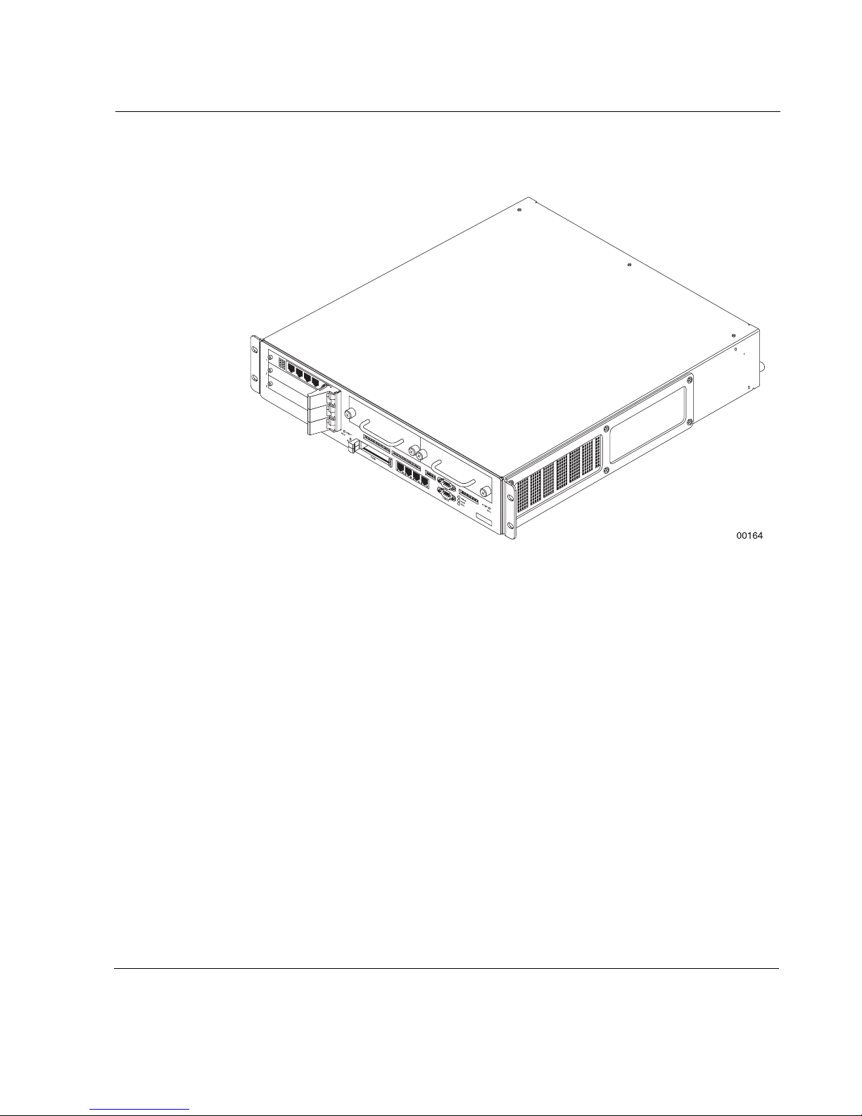
Figure 1 Front of Appliance
Appliance Overview
IP500 Series Installation Guide 21
1 Overview
a
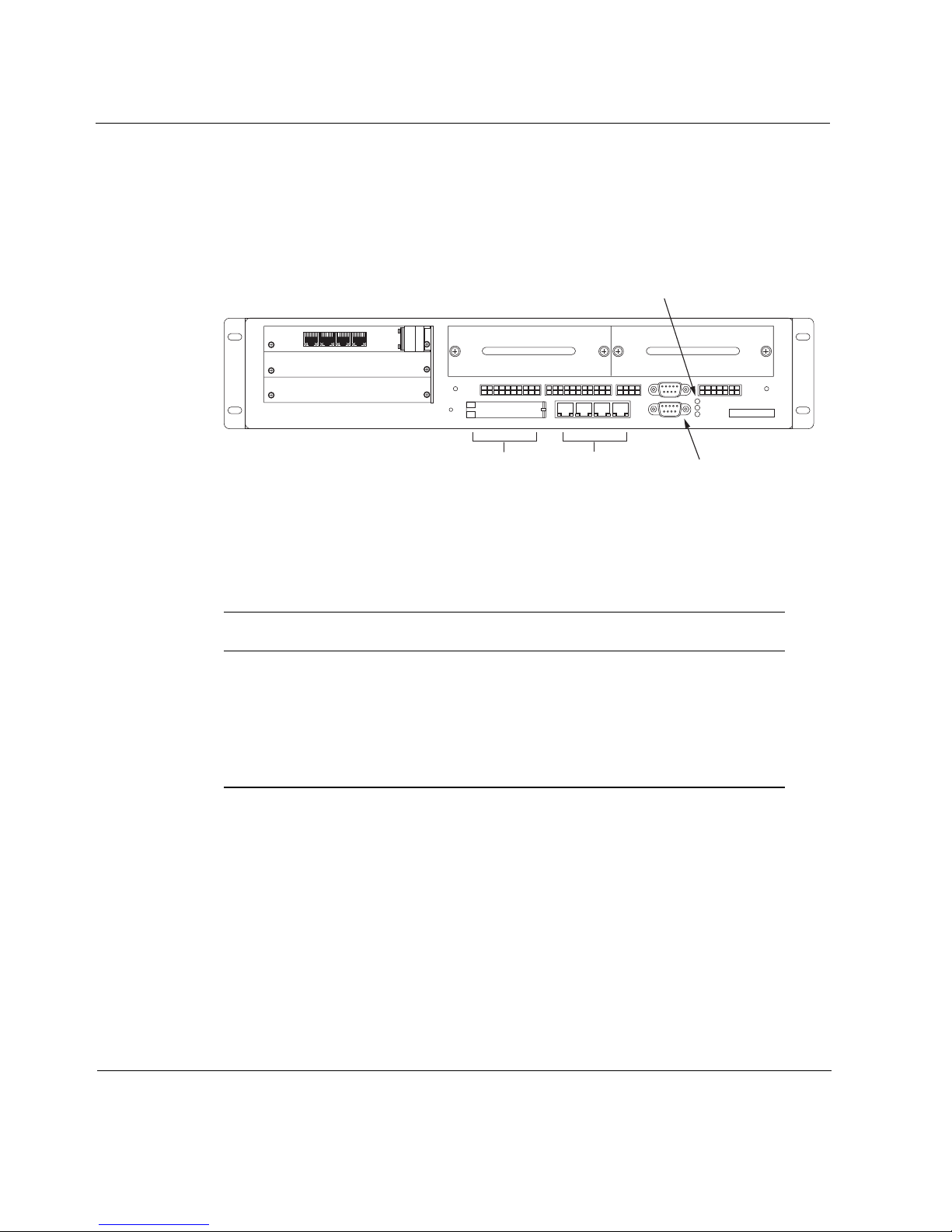
Figure 2 shows a more detailed view of the front of the appliance with the
console port, LEDs, and Ethernet interfaces labeled.
Figure 2 Front of Appliance Indicating Interfaces, Console Port, and
LEDs
System LEDs
1
2
3
ACTIVITY
HDD B
RESET
PCMCIA
LINK ACTIVITY LINK ACTIVITY LINK ACTIVITY LINK ACTIVITY
CONSOLE
AUX
PWR OK
ALERT
FAULT
ACTIVITY
HDD A
PCMCIA
Ethernet ports
Console port
00070
The three LEDs to the right of the console port are system indicators, which
function simultaneously. Table 2 describes the LED display meanings.
.
Table 2 System Status LEDs
Position Label Color Meaning
Top PWR Green Appliance receiving power
Middle ALERT Yellow Appliance not performing within
specifications
Bottom FAULT Red Appliance experiencing fault
22 IP500 Series Installation Guide
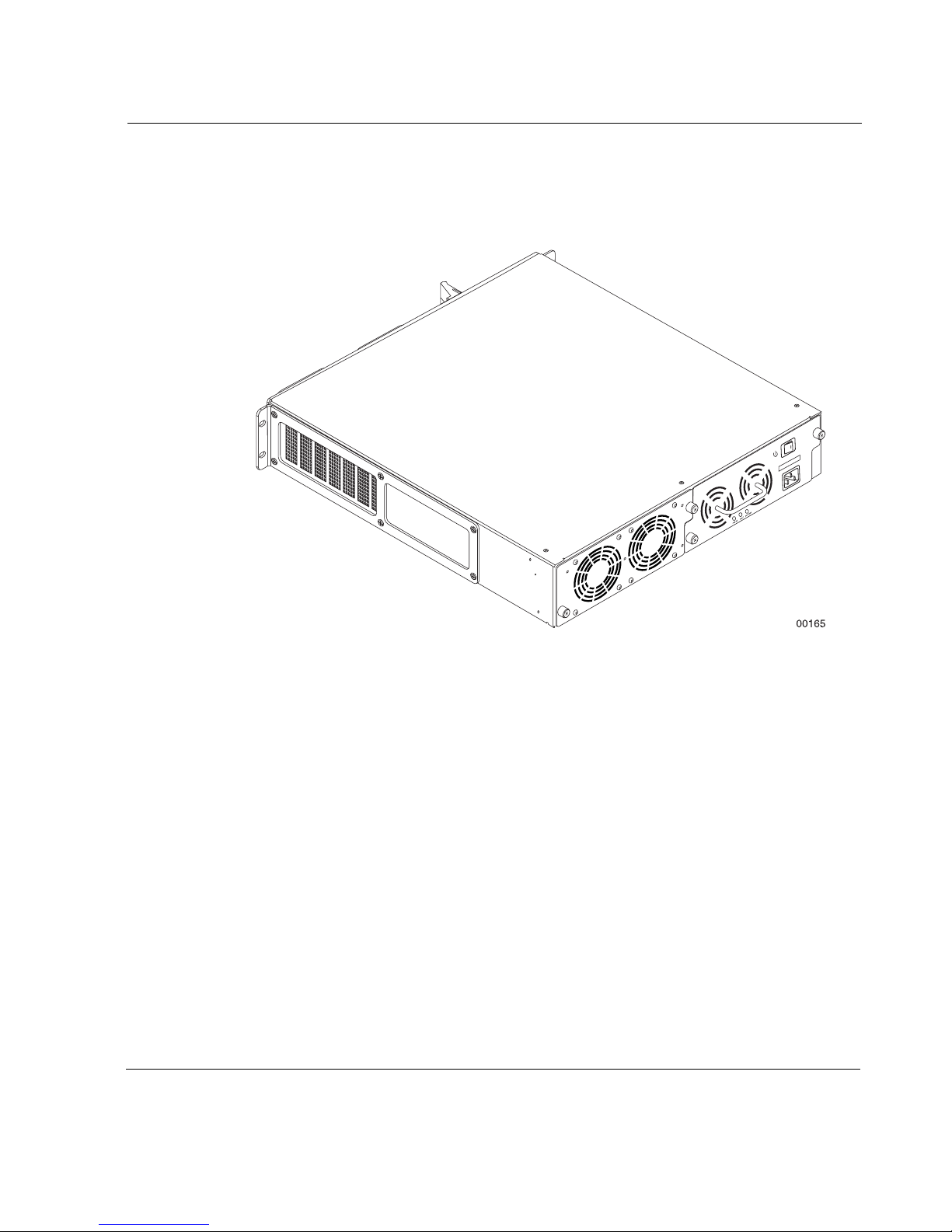
Figure 3 shows the rear of the appliance.
Figure 3 Rear of Appliance
Appliance Overview
IP500 Series Installation Guide 23
1 Overview
a
t
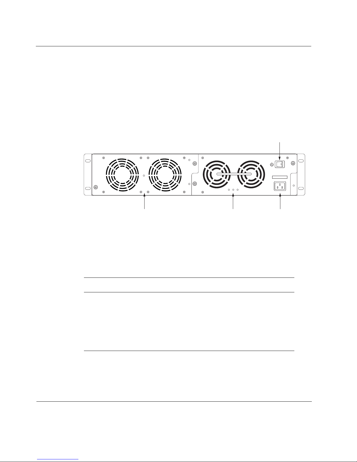
Figure 4 shows a more detailed view of the rear of the IP500 Series appliance,
with the on-off switch, power plug sockets, fan unit, and power LEDs labeled.
The fan unit, which is used to keep the appliance at proper operating
temperature, is on the left. This fan unit has two large fans. The power supply,
with two smaller fans, is on the right.
Figure 4 Rear of Appliance Indicating On-Off Switch, Power Plug
Socket, and Power Supply LEDs
On-Off switch
PWR OK FAULT OVR TEMP
Pow er supply LEDsFan unit
Pow er plug socke
00071
Three LEDs are located below the two fans on the power supply. Table 3
describes the power supply LED display meanings. All LEDs work
simultaneously.
.
Table 3 Power Supply LEDs
Position Label Color Meaning
Left PWR OK Green Unit receiving power
Center FAULT Red Unit not performing within
specifications
Right OVER
TEMP
Yellow Unit exceeding maximum
temperature specification
24 IP500 Series Installation Guide

Hardware Features
The basic IP500 Series hardware includes:
Four 10/100 BASE-T Ethernet ports
One EIA-232 console port with DB9 connector
One EIA-232 auxiliary port with DB9 connector
Two Type II PCMCIA slots
Two slots for 3.5-inch IDE hard-disk drive units
The IP500 Series appliance also has three compact PCI (cPCI) expansion
slots that support the following NICs:
Dual-port X.21 or V.35 serial interface
Single-port T1/E1 interface, with built-in channel service unit/data
service unit (CSU/DSU)
Single-port high speed serial interface (HSSI)
Single-port asynchronous transfer mode (ATM) interface
Site Requirements
Virtual private network (VPN) accelerator
Quad-port 10/100 BASE-T Ethernet interface
Single-port ISDN interface
Single- or dual-port Gigabit Ethernet interface
Note
Nokia Customer Support only supports NICs designed for the IP500
Series NSP. These NICs must be purchased from Nokia or from approved
resellers.
Site Requirements
Before installing an IP500 Series appliance, make sure that your computer
room or wiring closet conforms to the environmental specifications listed in
Appendix A, “Technical Specifications.”
IP500 Series Installation Guide 25

1 Overview
Caution
Do not place objects over the ventilation slots on the unit. Internal
components might overheat and become damaged.
Warning
An explosion might occur if the battery is incorrectly placed. Replace the
battery only with the same or equivalent type recommended by the
manufacturer. Dispose of used batteries according to the manufacturer’s
instructions.
Space Requirements
You can install the IP500 Series appliance in a standard 19-inch rack or as a
stand-alone appliance.
Rack Installation
The cover of the appliance is designed for front-screw mounting in a standard
19-inch rack. Each appliance requires the following space in a rack:
2 rack units (3.5 inches; 9 centimeters) of vertical space
18 inches (46 centimeters) behind the faceplate of the rack
6 inches (15 centimeters) behind the appliance to allow the back exit fan
to move air through the appliances
Caution
Do not place objects over the ventilation slots on the appliance.
Internal components might overheat and become damaged.
26 IP500 Series Installation Guide

Software Requirements
Warning
To reduce the risk of fire, electric shock, and personal injury when you use
the equipment, follow basic safety precautions. Do not use the product
near water.
Stand-alone or Stacked Installation
If you have more than one appliance, you can install the appliances standalone or you can stack the appliances. Follow these guidelines:
Provide sufficient clearance (about six inches) behind the appliance to
allow the back exit fan to move air through the appliance.
Do not remove the rubber feet that come with the appliances when you
stack them. The rubber feet prevent damage to the appliances and keep
appliances from sliding against each other.
Do not stack the appliances more than three high.
Do not stand the appliance on its side.
Software Requirements
The IP500 Series appliance supports the following operating system and
applications:
Operating system requirements—IPSO v3.3.1 or later.
FireWall and VPN software requirements—Check Point Firewall 4.1
(SP3 or later), and Check Point NG (FP2 or later).
Intrusion Detection software requirements—ISS RealSecure for Nokia
v5.0 or later.
IP500 Series Installation Guide 27

1 Overview
28 IP500 Series Installation Guide

2 Installing the IP500 Series
Appliance
This chapter describes how to install the appliance. The following topics are
covered:
Connecting Power
Connecting to the Console
Connecting Network Interfaces
Caution
Protect the IP530 appliance and other electronic equipment from
static discharge by making sure you are properly grounded before
you touch any electronic components.
Connecting Power
The IP500 Series appliance comes with an internal DC power supply and a
cord for connecting the power supply to a power source. The cord is specific
to the country in which the appliance was purchased.
IP500 Series Installation Guide 29

2 Installing the IP500 Series Appliance
Note
The power supply automatically configures itself to the input voltage: 100
to 130V and 200 to 240V AC.
To connect the IP500 Series appliance to a power source
1. Plug the power cord into the power plug socket on the back of the
appliance.
2. Plug the other end of the cord into a grounded power strip or wall outlet.
3. Turn on the appliance by toggling the on-off switch on the back of the
appliance to the right.
You hear the appliance fans, which run whenever the appliance is on. The
PWR LED glows green.
Connecting to the Console
The IP500 Series appliance comes with a null-modem serial cable with a
DB-9 connector. Use this cable to connect one of the following consoles to the
appliance:
A standard VT100-compatible terminal
A DOS or Windows computer running a terminal emulation program
(such as HyperTerminal)
A UNIX workstation
Note
The console port on the appliance is an EIA-232 data terminal equipment
(DTE) interface with 8 data bits, no parity, and 1 stop bit, running at
9600 bps.
30 IP500 Series Installation Guide
 Loading...