

Nokia IP350, IP380 Appliance Installation Manual

IP350 and IP380
Appliance Installation
Guide
Part No. N450709003 Rev A
Published September 2004

COPYRIGHT
©2003 Nokia Corporation. All rights reserved.
Rights reserved under the copyright laws of the United States.
RESTRICTED RIGHTS LEGEND
Use, duplication, or disclosure by t he Unite d States Government is subject to restrictions as set
forth in subparagr aph (c)(1)(ii) of the Rights in Technical Data and Computer Software clause at
DFARS 252.227-701 3. Notwithstanding any other license agreement that may pertain to, or
accompany the delivery of, this computer software, the r ights of the United States Government
regarding its use, reproduction, and disclosure are as set forth in the Commercial Computer
Software-Restricted Rights clause at FAR 52.227-19.
IMPORT ANT NOTE TO USERS
This software and hardware i s provided by Nokia Corporation as is and any expre ss or implied
warranties, including, but not limited to, implied warranties of merchantability and fitness for a
particular purpose are disclaimed. In no event shall Nokia, or its affiliates, subsidiaries or
suppliers be liable for any direct, indirect, incidental, special, exemplary, or consequential
damages (incl uding, but not limited t o, procurement of substitute goods or se rvices ; loss of use,
data, or profits; or business interruption) however caused and on any theory of liability, whether in
contract, strict liability, or tort (including negligence or otherwise) arising in any way out of the use
of this software, even if advised of the possibility of such damage. Nokia reserves the right to
make changes without further notice to any products herein.
TRADEMARKS
Nokia i s a r e gi ster e d tr ad emar k o f No ki a Co rpor a tio n. Ot her p r oduc t s me nt ione d i n t h is doc um ent
are trademarks or registered trademar ks of their resp ective holders.
2 IP350 and IP380 Appliance Installation Guide

Nokia Co n tac t Inf or m ation
Corporate Headquarters
Web Site http://www.nokia.com
Telephone 1-888-477-4566 or
1-650-625-2000
Fax 1-650-691-2170
Mail
Address
Regional Contac t In for m at i on
Americas Nokia Interne t Communications
Europe,
Middle East,
and Africa
Asia-Pacific 438B Alexandra Road
Nokia Custom er Supp or t
Web Site: https://support.nokia.com/
Email: tac.support@nokia.com
Nokia Inc.
313 Fairchil d Drive
Mountain View, California
94043-2215 USA
313 Fairchil d Drive
Mountain View, CA 94043-2215
USA
Nokia House, Summit Avenue
Southwood, Farnborough
Hampshire GU14 ONG UK
#07-00 Alexandra Technopark
Singapore 119968
Tel: 1-877-997-9199
Outside USA and Canada: +1 512-437-7089
email: ipsecurity.na@nokia.com
Tel: UK: +44 161 601 8908
Tel: France: +33 170 708 166
email: ipsecurity.emea@nokia.com
Tel: +65 6588 3364
email: ipsecurity.apac@nokia.com
Americas Europe
Voice: 1-888-361-5030 or
Fax: 1-613-271-8782 Fax: +44 (0) 125-286-5666
Asia-Pacific
Voice: +65-67232999
Fax: +65-67232897
IP350 and IP380 Appliance Installatio n Guide 3
Voice: +44 (0) 125-286-8900
1-613-271-6721
021216

4 IP350 and IP380 Appliance Installation Guide

Contents
About this Guide . . . . . . . . . . . . . . . . . . . . . . . . . . . . . . . . . . . . . .11
In This Guide . . . . . . . . . . . . . . . . . . . . . . . . . . . . . . . . . . . . . . . . . 11
Conventions This Guide Uses . . . . . . . . . . . . . . . . . . . . . . . . . . . . 12
Notices . . . . . . . . . . . . . . . . . . . . . . . . . . . . . . . . . . . . . . . . . . . . 12
Command-Line Conventions. . . . . . . . . . . . . . . . . . . . . . . . . . . . 13
Text Conventions . . . . . . . . . . . . . . . . . . . . . . . . . . . . . . . . . . . . 15
Related Documentation . . . . . . . . . . . . . . . . . . . . . . . . . . . . . . . . . 16
1 Overview . . . . . . . . . . . . . . . . . . . . . . . . . . . . . . . . . . . . . . . . . . . 17
About the Nokia IP350 and IP380 IP Security Appliances. . . . . . . 17
Memory . . . . . . . . . . . . . . . . . . . . . . . . . . . . . . . . . . . . . . . . . . . . 17
Encryption Acceleration. . . . . . . . . . . . . . . . . . . . . . . . . . . . . . . . 18
Managing the IP350 and IP380 Appliance. . . . . . . . . . . . . . . . . . . 18
Appliance Overview . . . . . . . . . . . . . . . . . . . . . . . . . . . . . . . . . . . . 19
Ethernet Management Ports . . . . . . . . . . . . . . . . . . . . . . . . . . . . 20
Built-in Console Port . . . . . . . . . . . . . . . . . . . . . . . . . . . . . . . . . . 21
Built-in AUX Port . . . . . . . . . . . . . . . . . . . . . . . . . . . . . . . . . . . . . 23
Status LEDs . . . . . . . . . . . . . . . . . . . . . . . . . . . . . . . . . . . . . . . . 24
Site Requirements . . . . . . . . . . . . . . . . . . . . . . . . . . . . . . . . . . . . . 25
Software Requirements . . . . . . . . . . . . . . . . . . . . . . . . . . . . . . . . . 26
2 Installing the Appliance . . . . . . . . . . . . . . . . . . . . . . . . . . . . . . . 27
Rack Mounting the Appliance. . . . . . . . . . . . . . . . . . . . . . . . . . . . . 27
Connecting Power and Turning the Power On. . . . . . . . . . . . . . . . 29
Connecting Network Interfaces . . . . . . . . . . . . . . . . . . . . . . . . . . . 30
IP350 and IP380 Appliance Installatio n Guide 5

3 Performing the Initial Configuration . . . . . . . . . . . . . . . . . . . . . 33
Using a Console Connection to Perform the Initial Configuration . 34
Accessing Nokia Network Voyager . . . . . . . . . . . . . . . . . . . . . . . . 36
Accessing Voyager Reference Information. . . . . . . . . . . . . . . . . 37
Using Voyager to Monitor an IP350 or 380 Appliance . . . . . . . . 38
Using Nokia Horizon Manager. . . . . . . . . . . . . . . . . . . . . . . . . . . . 38
4 Installing and Replacing Network Interface Cards . . . . . . . . . 39
Deactivating Configured Interfaces . . . . . . . . . . . . . . . . . . . . . . . . 40
Remov ing, Installing, and Replacing NICs. . . . . . . . . . . . . . . . . . . 40
Configuring and Activating Interfaces . . . . . . . . . . . . . . . . . . . . . . 46
Monitoring Network Interface Cards. . . . . . . . . . . . . . . . . . . . . . . . 47
5 Connecting PMC Network Interface Cards . . . . . . . . . . . . . . . . 49
Dual-Port 10/100 Ethernet Interface, PMC . . . . . . . . . . . . . . . . . . 49
Ethernet PMC NIC Features. . . . . . . . . . . . . . . . . . . . . . . . . . . . 50
Ethernet NIC Connectors and Cables. . . . . . . . . . . . . . . . . . . . . 50
6 Installing and Replacing Other Components . . . . . . . . . . . . . . 53
Installing a PCMCIA Modem . . . . . . . . . . . . . . . . . . . . . . . . . . . . . 54
Replacing a Hard-Disk Drive . . . . . . . . . . . . . . . . . . . . . . . . . . . . . 55
Replacing or Upgrading Memory . . . . . . . . . . . . . . . . . . . . . . . . . . 59
Before You Start . . . . . . . . . . . . . . . . . . . . . . . . . . . . . . . . . . . . . 60
Adding or Replacing DIMMs . . . . . . . . . . . . . . . . . . . . . . . . . . . . 61
Installing an Encryption Accelerator Card . . . . . . . . . . . . . . . . . . . 66
Before You Start . . . . . . . . . . . . . . . . . . . . . . . . . . . . . . . . . . . . . 67
Insta lling the Card . . . . . . . . . . . . . . . . . . . . . . . . . . . . . . . . . . . . 67
Configuring Software to Use Hardware Acceleration . . . . . . . . . 71
7 Using the Boot Manager . . . . . . . . . . . . . . . . . . . . . . . . . . . . . . . 73
Variables . . . . . . . . . . . . . . . . . . . . . . . . . . . . . . . . . . . . . . . . . . . . 74
Viewing the Variables and Other System Parameters . . . . . . . . 76
6 IP350 and IP380 Appliance Installation Guide

Setting the Variables. . . . . . . . . . . . . . . . . . . . . . . . . . . . . . . . . . 78
Other commands. . . . . . . . . . . . . . . . . . . . . . . . . . . . . . . . . . . . . 80
Booting the System . . . . . . . . . . . . . . . . . . . . . . . . . . . . . . . . . . . . 81
Using the Boot Manager to Install IPSO. . . . . . . . . . . . . . . . . . . . . 82
Protecting the Boot Manager with a Password . . . . . . . . . . . . . . . 83
Installing the Boot Manager . . . . . . . . . . . . . . . . . . . . . . . . . . . . . . 84
Upgrading the Boot Manager. . . . . . . . . . . . . . . . . . . . . . . . . . . . . 85
8 Troubleshooting . . . . . . . . . . . . . . . . . . . . . . . . . . . . . . . . . . . . . 87
General Troubleshooting Information. . . . . . . . . . . . . . . . . . . . . . . 87
Troubleshooting Routing Problems . . . . . . . . . . . . . . . . . . . . . . . . 97
A Technical Specifications . . . . . . . . . . . . . . . . . . . . . . . . . . . . . 103
Physical Dimensions . . . . . . . . . . . . . . . . . . . . . . . . . . . . . . . . . . 103
Space Requirements . . . . . . . . . . . . . . . . . . . . . . . . . . . . . . . . . . 103
NIC Interfaces . . . . . . . . . . . . . . . . . . . . . . . . . . . . . . . . . . . . . . . 104
B Compliance Information . . . . . . . . . . . . . . . . . . . . . . . . . . . . . . 1 05
Declaration of Conformity . . . . . . . . . . . . . . . . . . . . . . . . . . . . . . . 106
Compliance Statements. . . . . . . . . . . . . . . . . . . . . . . . . . . . . . . . 108
FCC Notice (US) . . . . . . . . . . . . . . . . . . . . . . . . . . . . . . . . . . . . . 109
Index . . . . . . . . . . . . . . . . . . . . . . . . . . . . . . . . . . . . . . . . . . . . . . 111
IP350 and IP380 Appliance Installatio n Guide 7

8 IP350 and IP380 Appliance Installation Guide

Figures
Figure 1 Component Locations Front View . . . . . . . . . . . . . . . . . 19
Figure 2 Component Locations Rear View . . . . . . . . . . . . . . . . . 20
Figure 3 Ethernet Management Ports Details . . . . . . . . . . . . . . . 20
Figure 4 Pin Assignments for Console Connection . . . . . . . . . . . 22
Figure 5 Pin Assignments for Modem Connection . . . . . . . . . . . 23
Figure 6 Appliance Status LEDs . . . . . . . . . . . . . . . . . . . . . . . . . 24
Figure 7 Mounting Screws Location . . . . . . . . . . . . . . . . . . . . . . 28
Figure 8 Adjustable Mounting Brackets . . . . . . . . . . . . . . . . . . . . 28
Figure 9 Back Panel Power Switch . . . . . . . . . . . . . . . . . . . . . . . 29
Figure 10 Voyager Reference Access Points . . . . . . . . . . . . . . . 37
Figure 11 Dual-Port Ethernet NIC Front Panel Details . . . . . . . . 50
Figure 12 Output Connector for the Ethernet Cable . . . . . . . . . . 51
Figure 13 Ethernet C rossover -C able Pin Co nnections . . . . . . . . 52
Figure 14 Hard-Disk Drive Location . . . . . . . . . . . . . . . . . . . . . . 55
Figure 15 DIMM Socket Locations . . . . . . . . . . . . . . . . . . . . . . . 60
IP350 and IP380 Appliance Installatio n Guide 9

10 IP350 and IP380 Appliance Installatio n Guide

About this Guide
This manual provides information for the installation and use of the Nokia
IP350 and IP380 appliance . Installation and main tenance should be perf ormed
by experienced technicians or Nokia-approved service providers only.
This preface provides the following information:
In This Guide
Conventions This Guide Uses
Related Documentation
In This Guide
This guide is organized into the following chapters and appendixes:
Chapter 1, “Overview” presents a general overview of the IP350 and
IP380 appliances.
Chapter 2, “Installing the Appliance” explains how to rack-mount the
appliance and how to physically connect it to a network and power.
Chapter 3, “Performing the Initial Configuratio n” explains how to make
the appliance available on the network.
Chapter 4, “Installing and Replacing Network Interfac e Cards” explains
how to install, monitor, and replace network interface cards (NICs).
Chapter 5, “Connecting PMC Network Interface Cards” explains how to
connect to and use each of the supported NICs.
IP350 and IP380 Appliance Installatio n Guide 11

Chapter 6, “Install ing and Repla cing Othe r Components” expla ins how to
install or r eplace PCMCIA modems, memory, the hard-disk drive, and an
encryption accelerator card (IP380 only).
Chapter 7, “Using the Boot Manager” expl ains how to use the boot
manager, which is part of the IPSO software.
Chapter 8, “Tr oubleshooting” discusses problems you might encounter
and proposes soluti ons to these problems.
Appendix A, “Technical Specifications” gives technical specifications
such as interface characteristics.
Appendix B, “Warranty and Software License” contains Nokia warranty
and software license information.
Appendix C, “General Public Lic ensed Software” provides infor mation
about publicly lic en sed software that comes with the appliance.
Appendix B, “Compliance Info rmation” includes compliance and
regulatory inf ormation.
Appendix E, “Glossary” provides a glossary of acronyms used in this
document.
Conventions This Guide Uses
The following sections describe the conventions this guide uses, including
notices, text conv entions, and command-line conventions.
Notices
Warning
Warnings advise the user that bodily injury might occur because of a
physical hazard.
12 IP350 and IP380 Appliance Installatio n Guide

Caution
Cautions indicate potential equipment damage, equipm ent
malfunction, loss of performance, loss of data, or interruption of
service.
Note
Notes provide information of special interest or recommendations.
Command-L ine Conv e nt ions
This section d efi nes the el em en ts of comm an d s that are av ail ab le in N o kia
Internet Communica tions products. You might encounter one or more of the
following elements on a command-line path.
Conventions This Guide Uses
Table 1 Command-Line Conventions
Convention Description
command This required element is usuall y the pr oduct name or other
short word that invokes the product or calls the compiler or
preprocessor script for a compiled Nokia product. It might
appear alone or precede one or more options. You must
spell a command exactly as shown and use lowercase
letters.
Italics Indicates a variab le i n a comman d that yo u must s upply. For
example:
delete interface if_name
Supply an interface name in place of the variable. For
example:
delete interface nic1
IP350 and IP380 Appliance Installatio n Guide 13

Table 1 Command-Line Conventions (continued)
Convention Description
angle brackets < > Indicates arguments for which you must supply a value:
retry-limit <1–100>
Supply a value. For exam ple:
retry-limit 60
Square brackets [ ] Indicates optional arguments.
delete [slot slot_num]
For example:
delete slot 3
Vertical bars, also
called a pipe
(|)
Separates alternative, mutually exclusive elements.
framing <sonet | sdh>
To complete the command, supply the value. For example:
framing sonet
or
framing sdh
-flag A flag is usuall y an abbreviation for a function, menu, or
option name, or for a compiler or preprocessor argument.
You must enter a flag exactly as shown, including the
preceding hyphen.
.ext A filename extension, such as .ext, might follow a variable
that represents a filename. Type thi s extension exactly as
shown, im mediatel y aft er t he name of t he fi le. Th e ex tensio n
might be optional in certain products.
14 IP350 and IP380 Appliance Installatio n Guide

Table 1 Command-Line Conventions (continued)
Convention Description
( . , ; + * - / ) Punctuation and mathematical notations are literal symbols
' ' Single quotation marks are lit e ral symbols that you m ust
Text Conventions
Table 2 describes the text conventions this guide uses.
Table 2 Text Conventions
Convention Description
Conventions This Guide Uses
that you must enter exactly as shown.
enter as shown.
monospace font
Indicates com mand syntax, or represent s computer or
screen output, for example:
Log error 12453
bold monospace font Indicates text you enter or type, for exam ple:
# configure nat
Key names Keys that you press simul taneously are linked by a
plus sign (+ ) :
Press Ctrl + Alt + Del.
Menu commands Menu commands are sep arat ed by a greater than
sign (> ):
Choose File > Open.
IP350 and IP380 Appliance Installatio n Guide 15

Table 2 Text Conventions (continued)
Convention Description
The words enter and type Enter indicates you type something and then press
the Return or Enter key.
Do not press the Return or Enter key when an
instructi on says type.
Italics
Related Document at ion
The IP350 and IP380 documentation set consists of Release N o tes for the
Nokia software release you are running, the IP350 and IP380 Appliance
Installat ion Guide (this document), a Voyager inline help featur e, and the
Voyager Reference Guide (online).
You can find the IP350 and IP380 Appli ance Installation Guide in PDF on the
World Wide Web support site (https://support.n okia.com/).
You can access inline help and the Voyager Reference Guide from Voyager.
To access inline help f or a specific subject, click the Help button next to the
subject.
• Emphasizes a point or denotes new terms at the
place where they are def ined in the text.
• Indicates an extern al book title refer ence.
• Indicates a variab le i n a com ma nd:
delete interface
if_name
Access the Voyager Reference Guide for tasks, exa mpl es, an d mo re
information by clicking the Doc button.
You can order Check Point documentation from Nokia or download it from
the Nokia support site at https://support.nokia.com/.
16 IP350 and IP380 Appliance Installatio n Guide

1 Overview
This chapter provides an overview of the IP350 and IP380 appliances and the
requirements for using those appliances. The following topics are covered:
About the Nokia IP350 and IP380 IP Security Appliances
Managing the IP350 and IP380 Appliance
Site Requirements
Software Require ments
Managing the IP350 and IP380 Appliance
About the Nokia IP350 and IP380 IP Security
Appliances
The Nokia IP350 and IP380 IP security appl iances combine the power of
Nokia IPSO software with your choice of firewall, VPN, and intrusion
detection security applications. Both platforms share the same one-rack unit
(1 RU) size and support the same selection of network interface cards.
Memory
The IP350 appliance supports from 256 MB to 512 MB of memory.
The IP380 appliance support s from 256 MB to 1 GB of memory and provides
approximately twice the throughput of the IP350.
IP350 and IP380 Appliance Installatio n Guide 17

1 Overview
Encryption Acceleration
Both the IP350 and IP380 applia nces provide built-in hardware-based
encryptio n accele ration. The IP380 appliance also supports an optional
encryption accelerator card to further enhance VPN performance.
This guide provides documentation for both the IP350 and IP380 appliances.
Most of the information for how to use these two appliances is the same.
Where differences exist, they are noted in the documentation.
The Nokia IP350 and IP380 appliances are ideally suited for growing
companies and satellite offices that want high-performance IP routing
combined with th e industry-lead ing Check Point VPN-1/Fire W all-1 e nterprise
security suite. The small size of the IP350 and IP380 appliance makes them
ideal for install ation s that n eed to con serv e s pace.
As network de vices, the I P350 and I P380 a ppliance s s upport a c omprehe nsive
suite of IP-routing functions and protocols , inc luding RIPv1/RIPv2, IGRP,
OSPF and BGP4 for unicast traffic, and DVMRP for multicast traffic. The
integrated router functionality el iminates the need for separate intra net and
access routers in se curi ty app l icat ions .
Managing the IP350 and IP380 Appliance
You can manage the IP350 and IP380 appliances by using one of the
following int erf aces:
Nokia Network Voyager—an SSL-secured, Web-based element
management interface to Nokia IP security platforms. Voyager is
preinstalled on the IP350 and IP380 appliance and enabled through the
IPSO operating system. With Voyager, you can manage, monitor, and
configure the IP350 and IP380 appliance from any authorized location
within the network by using a standard W eb browser.
For information a bout how to access Voya ger and the related reference
mat erial s, see “Accessing Nokia Network Voyager” on page 36.
The I P SO co mman d- l ine i nt er f ac e (CL I) —an SSHv2- secu red inte rfac e
that enables you to easily configure Nokia IP security platforms
18 IP350 and IP380 Appliance Installatio n Guide
Appliance Overview
from the command line. Everything that you can accomplish with
Voyager—manage, monitor, and configure the IP350 and IP380
appliance—you can also do with the CLI.
For information about how to access the CLI, see the Nokia CLI
Reference Guide for IPSO v3.6 or later.
Nokia Horizon Manager—a secure GUI-bas ed sof tware image
management application. W it h Horizon Manager, you can securely inst al l
and upgrade the Nokia proprietar y IPSO operating sy stem, plus hardware
and third-party applications such as Check Point FireWall-1 and
RealSecure for Nokia. Horizon Manager can perform installations a nd
upgrades on up to 2,500 Nokia IP security plat forms, offering
administrators the most rapid and depend able upgrade to Check Point NG.
For information about how to obtain Hor izo n Manager, see “Nokia
Contact Information” on page 3.
Appliance Over vie w
The following figures show component locations for the IP350 and IP380.
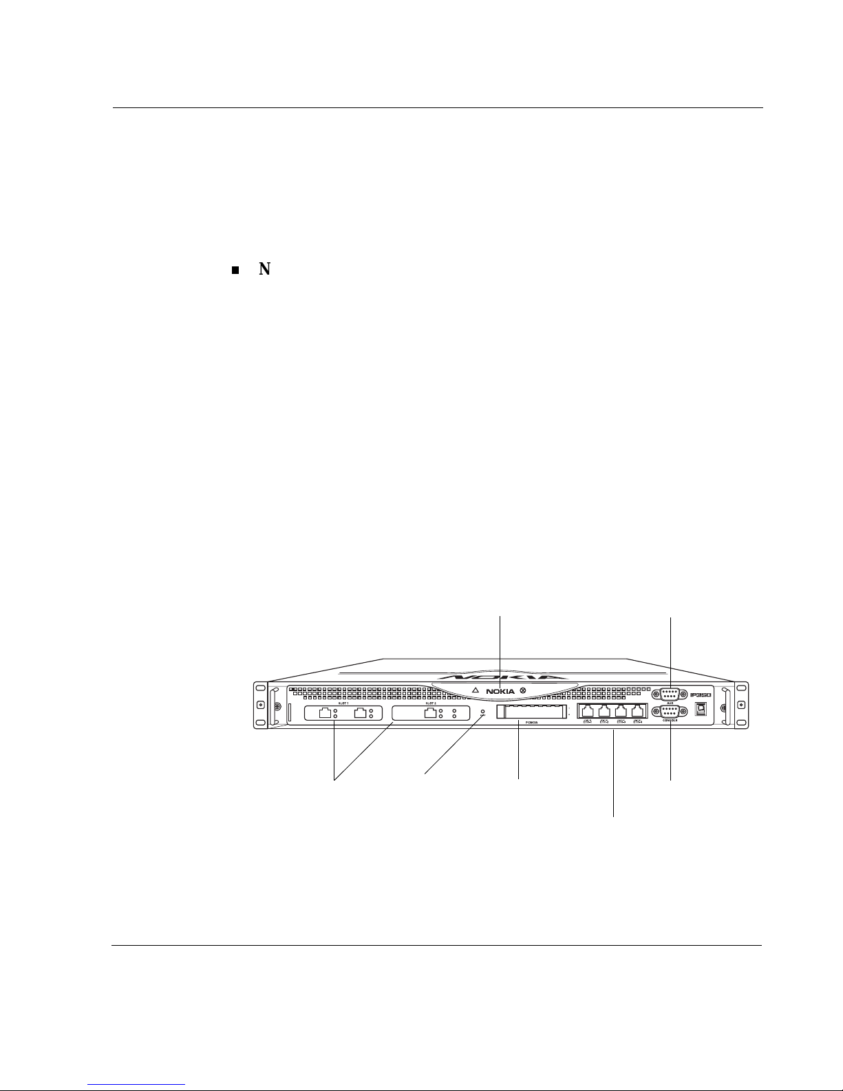
Figure 1 Component Locations Front View
PMC interfaces
Status LEDs Modem (AUX) port
PCMCIA slotsReset switch
Built-in Ethe rnet ports
(10/100 Mbp s)
Console port
00248a
IP350 and IP380 Appliance Installatio n Guide 19
1 Overview
s
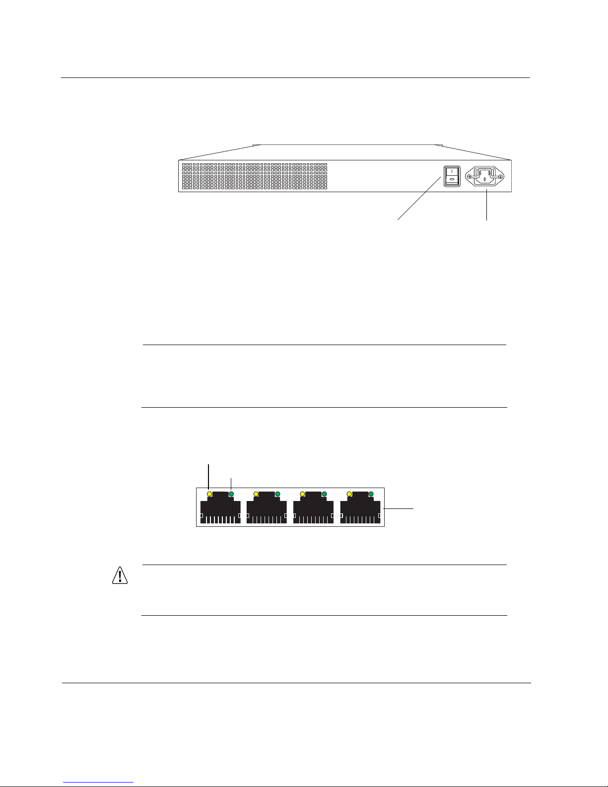
Figure 2 Component Locations Rear View
Ethernet Management Ports
The Ethernet management ports are located on the front of the appliance.
Figure 3 shows the la yout of the Ethernet management ports and link LEDs.
Note
The Ethernet management ports are intended for management purposes.
These ports do not provide the same performance as Ethernet cards in
the PMC slots.
00249
Power plugPower switch
Figure 3 Ethernet Man age m ent Ports Details
Activity LED (yellow)
Link LED (green)
RJ-45 connect or
00120
Caution
Cables that connect to the Ethernet ports must be IEEE 802.3
compliant to prevent potential data loss.
20 IP350 and IP380 Appliance Installatio n Guide

The IP350 and IP380 appliances include two PMC (PCI mezzanine cards)
expansion slots f or Nokia supported network interface cards. For information
about using this LAN card, see page 49
The IP350 and IP380 appliances also include a PCMCIA slot that supports
PCMCIA mod em s . Se e “Installing a PCMCIA Modem” on page 54.
Note
Nokia products only support NICs purchased from Nokia Corporation or
Nokia-approved resellers. The Nokia Global Support Services group can
only provide support for Nokia products that use Nokia-approved
accessories. For sales or reseller information, contact a Nokia service
provider listed in the “Nokia Cont act In fo rm at ion” on page 3.
Built-in Console Port
Appliance Overview
.
Use the built- in console por t, shown in Figure 1 to supply the info rmation that
makes the appliance available on the network. Figure 4 provides pin
assignment information for console connections.
IP350 and IP380 Appliance Installatio n Guide 21

1 Overview
1
Figure 4 Pin Ass ignment s f or Cons ole Conne ction
Pin# Assignment I nput/Output
1 DCD Input
2 RXD Input
1
69
5
70000
3TXD Output
4DTR Output
5GND
6 DSR Input
7RTS Output
8 CTS Input
9DTR Output
22 IP350 and IP380 Appliance Installatio n Guide

Built-in AUX Port
1
Use can use the AUX port, shown in Figure 1, to establish a modem
connection for managing the appliance. Figure 5 provides pin assign ment
information for modem connections.
Figure 5 Pin Ass ignme nts for Modem Co nnect ion
Appliance Overview
1
69
Pin Input/Output
1 (DCD) Input 8 (DCD) 7 (RTS)
2 (RXD) Input 2 (TXD) 3 (TXD)
3 (TXD) Output 3 (RXD) 2 (RXD
4 (DTR) Output 20 (DTR) 6 (DSR)
5 (GND) 7 (GND) 5 (GND)
6 (DSR) Input 6 (DSR) 4 (DTR)
7 (RTS) Output 4 (RTS) 1 (DCD)
5
70000
To DB25
Cable Out
To DB9
Cable Out
8 (CTS)
9 (RI)
IP350 and IP380 Appliance Installatio n Guide 23
8 (CTS) Input 5 (CTS) 1 (DCD)
9 (RI) Output 22 (RI) 4 (DTR)
1 Overview
!
!
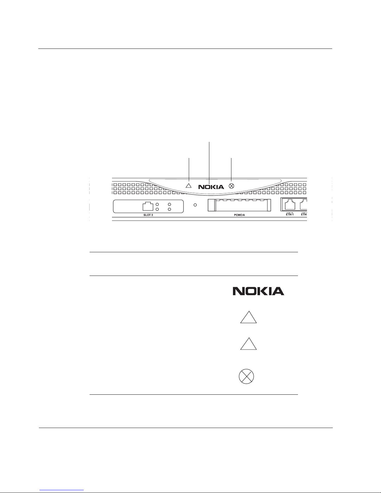
Status LED s
You can monitor the basic operation of IP350 and IP380 appliances and
network interf ace cards (NICs) by checking their status LEDs. The system
status LEDs are located on the front panel of the a ppliance, as Fi gure 6 shows.
Figure 6 Appliance Status LEDs
Power-status
Voltage
Table 3 Appliance Status LEDs
Stat us Indi cation Explana tion
Solid Power on
Solid Unit is experiencing an
internal Voltage problem
Fan problem
LED Front Panel
Symbol
Blinking The unit is experiencing
Solid red One or more fans are not
24 IP350 and IP380 Appliance Installatio n Guide
a temperature proble m
operating properly, or a
5V, 3.3V, or 12V fu se is
blown

The location and meaning of the status LEDs for network interface cards are
explained in Chapter 5, “Connecting PMC Network Interface Cards.”
For information on the built-in Ethernet interface LEDs, se e “Ethernet
Management Ports” on page 20.
For information on the Dual port Ethernet card LEDs, see “Dual-Port 10/
100 Ethernet Interface, PMC” on page 49.
Site Requirements
Before you install an IP350 or IP380 appliance, ensure that your compute r
room or wiring closet conforms to the environmental specifications listed in
Appendix A, “Technical Specifications.”
Warning
Hazardous radiation exposure can occur if you use controls, make
performance adjustments, or follow procedures that are not described in
this document.
Site Requirements
Warning
An explosion can occur if the battery is incorrectly placed. Replace only
with the same or equivalent type battery recommended by the
manufacturer. Dispose of used batteries according to the manufacturer's
instructions.
Warning
To reduce the risk of fire, electric shock, and injury when you use
telephone equipment, follow basic safety precautions. Do not use the
product near water.
IP350 and IP380 Appliance Installatio n Guide 25
1 Overview
Caution
Do not place objects over the ventilation holes on the IP350 or IP380
appliance. The components might overheat and become damaged.
Caution
For IP350 or IP380 appliances intended for shipment outside of the
United States, the cord might be optional. If a cord is not provided,
use a power cord rated at 6A, 250V , maximum 15 feet long, made of
HAR cordage and IEC fittings approved by the country of end use.
Software Requirements
IP350 and IP380 appliances support the following operating system and
applications when this guide was published.
Operating System Requirements—IPSO v 3.5.1, 3.7 and later.
Firewall and VPN Software Requi rements—Check Point NG VPN-1/
FW-1 FP2 or higher.
Intrusion Detection Softwa re Require ments—ISS RealSecur e version 6.5
or 7.0.
For information about changes to the software requirements or additional
applications that have become available since this guide was published,
contact y our Nokia service provider, as listed in “Noki a Contact Informat ion”
on page 3.
26 IP350 and IP380 Appliance Installatio n Guide

2 Installing the Appliance
This chapter describes how to install the Nokia IP350 and IP380 appliances.
The following topics are covered:
Rack Mounting the Appliance
Connecting Power and T urning the Power On
Connecting Network Interfaces
Caution
Protect your IP350 and IP380 appliance and other electronic
equipment from static discharge by making sure you are properly
grounded before you touch any electronic components.
Note
The operating temperature range for the IP350 and IP380 appliance is
0° C to 45° C.
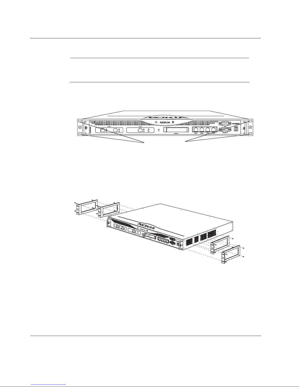
Rack Mounting the Appliance
The IP350 and IP380 appliances mount in a standard 19-inch rack with four
mounting screws as Figure 7 shows.
IP350 and IP380 Appliance Installatio n Guide 27
2 Installing the Appliance
Note
To avoid damaging your equipment, Nokia recommends that you use all
four rack-mounting bolts when you install your appliance on the rack.
Figure 7 Mounting Screws Location
Mounting Screws
00248a
You can relocate the mounting brackets as Figure 8 shows so that the unit is 2
inches forward of the rack.
Figure 8 Adjustable Mounting Brackets
00251a
Two mounting positions are available allowing you to mount the unit either
flush with the rack, or two inches forward of the rack.
28 IP350 and IP380 Appliance Installatio n Guide

Connecting Power and Turning the Power On
Caution
Blocking ventilation openings during installation may result in
damage to the appliance.
Connecting Power and Turning the Power On
The power plug and power switch for the IP350 and IP380 appliances are
located on the back of the appliance as Figure 9 shows.
Note
The IP350 and IP380 appliance power supplies automatically detec t the
input voltage (115VAC [90 to 132] or 220VAC [180 to 264]) and configure
themselves appropriately.
Figure 9 Back Panel Power Switch
00249
Power plugPower switch
To c onnect the power supply
1. Connect the power cord securely int o the power socket on the back of the
appliance.
2. Plug the other end of the cord into a three-wi re grounded power strip or
wall outlet.
3. Press the power supply switch to the “on” position to activate the IP350
and IP380 appliance.
IP350 and IP380 Appliance Installatio n Guide 29

2 Installing the Appliance
The fan unit on the power supply turns on when you press the power switch.
Verify that the fans are running after you press the switch.
Check the power LED on the front panel of the appliance (the Nokia logo) to
ensure that the power suppl y is ope rating c orrectly. The power LED should be
illuminate d. For more information about the system status LEDs, see “Status
LEDs” on page 24.
If the power supply fans are not running, or if the power LED is not
illuminated:
Check the power supply cord to make sure it is properly connected.
Make sure the power supply switch is on.
Make sure the chassis assembly is pushed all t he way in from the front of
the platform.
Make sure that power is turned on to the power strip or wall receptacle
you plugged the appliance in to.
If the fans are still not running, or if the power LED does not illuminate,
contact your Nokia service provider as listed in “Nokia Cont act In fo rm at ion”
on page 3 for technical support.
Connecting Network Interfaces
Connect at least one network interface to the network to use as the Voyager
system man a ge me n t inter fac e. Th is int er face is conf igu re d du ri ng th e sys tem
startup procedure, which is described in Chapter 3, “Performing the Initial
Configuration.”
You can also connect the remaining LAN interface wires at this point,
although you are not required to do so.
To connect Ethernet devices:
Use a straight-through RJ-45 cable to connect to a 10-Mbps or
100-Mbps hub.
Use a crossover RJ-45 cable to connect directly to a host.
For details, see “Ethernet NI C Co nnec tors and Cables” on page 50.
30 IP350 and IP380 Appliance Installatio n Guide
 Loading...