

Nokia IP2255 - Security Appliance Installation Manual

Nokia IP2255 Security
Platform Installation Guide
Part No. N450000275 Rev 002
Published March 2007

COPYRIGHT
©2007 Nokia. All rights reserved.
Rights reserved under the copyright laws of the United States.
RESTRICTED RIGHTS LEGEND
Use, duplication, or disclosure by the United States Government is subject to restrictions as set
forth in subparagraph (c)(1)(ii) of the Rights in Technical Data and Computer Software clause at
DFARS 252.227-7013.
Notwithstanding any other license agreement that may pertain to, or accompany the delivery of,
this computer software, the rights of the United States Government regarding its use,
reproduction, and disclosure are as set forth in the Commercial Computer Software-Restricted
Rights clause at FAR 52.227-19.
IMPORTANT NOTE TO USERS
This software and hardware is provided by Nokia Inc. as is and any express or implied
warranties, including, but not limited to, implied warranties of merchantability and fitness for a
particular purpose are disclaimed. In no event shall Nokia, or its affiliates, subsidiaries or
suppliers be liable for any direct, indirect, incidental, special, exemplary, or consequential
damages (including, but not limited to, procurement of substitute goods or services; loss of use,
data, or profits; or business interruption) however caused and on any theory of liability, whether in
contract, strict liability, or tort (including negligence or otherwise) arising in any way out of the use
of this software, even if advised of the possibility of such damage.
Nokia reserves the right to make changes without further notice to any products herein.
TRADEMARKS
Nokia is a registered trademark of Nokia Corporation. Other products mentioned in this document
are trademarks or registered trademarks of their respective holders.
070101
2 Nokia IP2255 Security Platform Installation Guide

Nokia Contact Information
Corporate Headquarters
Web Site http://www.nokia.com
Telephone 1-888-477-4566
1-650-625-2000
Fax 1-650-691-2170
Mail
Address
Regional Contact Information
Americas Nokia Inc.
Europe,
Middle East,
and Africa
Asia-Pacific 438B Alexandra Road
Nokia Customer Support
Nokia Inc.
313 Fairchild Drive
Mountain View, California
94043-2215 USA
313 Fairchild Drive
Mountain View, CA 94043-2215
USA
Nokia House, Summit Avenue
Southwood, Farnborough
Hampshire GU14 ONG UK
#07-00 Alexandra Technopark
Singapore 119968
or
Tel: 1-877-997-9199
Outside USA and Canada: +1 512-437-7089
email: info.ipnetworking_americas@nokia.com
Tel: UK: +44 161 601 8908
Tel: France: +33 170 708 166
email: info.ipnetworking_emea@nokia.com
Tel: +65 6588 3364
email: info.ipnetworking_apac@nokia.com
Web Site: https://support.nokia.com/
Email: tac.support@nokia.com
Americas Europe
Voice: 1-888-361-5030 or
1-613-271-6721
Fax: 1-613-271-8782 Fax: +44 (0) 125-286-5666
Asia-Pacific
Voice: +65-67232999
Fax: +65-67232897
Voice: +44 (0) 125-286-8900
050602
Nokia IP2255 Security Platform Installation Guide 3

4 Nokia IP2255 Security Platform Installation Guide

Contents
About this Guide . . . . . . . . . . . . . . . . . . . . . . . . . . . . . . . . . . . . . .13
In this Guide . . . . . . . . . . . . . . . . . . . . . . . . . . . . . . . . . . . . . . . . . . 13
Conventions this Guide Uses . . . . . . . . . . . . . . . . . . . . . . . . . . . . . 14
Notices . . . . . . . . . . . . . . . . . . . . . . . . . . . . . . . . . . . . . . . . . . . . 14
Text Conventions . . . . . . . . . . . . . . . . . . . . . . . . . . . . . . . . . . . . 15
Related Documentation . . . . . . . . . . . . . . . . . . . . . . . . . . . . . . . . . 16
1 Overview . . . . . . . . . . . . . . . . . . . . . . . . . . . . . . . . . . . . . . . . . . . 19
About the Nokia IP2255 Security Platform. . . . . . . . . . . . . . . . . . . 19
Managing the Nokia IP2255 Appliance . . . . . . . . . . . . . . . . . . . . . 20
Nokia IP2255 Appliance Overview . . . . . . . . . . . . . . . . . . . . . . . . . 21
Ethernet Management Ports . . . . . . . . . . . . . . . . . . . . . . . . . . . . 23
Nokia Network Interface Cards . . . . . . . . . . . . . . . . . . . . . . . . . . 24
Console Port . . . . . . . . . . . . . . . . . . . . . . . . . . . . . . . . . . . . . . . . 26
Serial Port . . . . . . . . . . . . . . . . . . . . . . . . . . . . . . . . . . . . . . . . . . 27
System Status LEDs . . . . . . . . . . . . . . . . . . . . . . . . . . . . . . . . . . 29
Fan Unit. . . . . . . . . . . . . . . . . . . . . . . . . . . . . . . . . . . . . . . . . . . . 30
Storage Devices . . . . . . . . . . . . . . . . . . . . . . . . . . . . . . . . . . . . . 31
Power Supplies . . . . . . . . . . . . . . . . . . . . . . . . . . . . . . . . . . . . . . 31
Product Disposal . . . . . . . . . . . . . . . . . . . . . . . . . . . . . . . . . . . . . . 32
Site Requirements, Warnings, and Cautions . . . . . . . . . . . . . . . . . 33
Software Requirements . . . . . . . . . . . . . . . . . . . . . . . . . . . . . . . . . 34
2 Installing Nokia IP2255 Appliances . . . . . . . . . . . . . . . . . . . . . . 37
Rack Mounting the Security Platform. . . . . . . . . . . . . . . . . . . . . . . 37
Before You Begin . . . . . . . . . . . . . . . . . . . . . . . . . . . . . . . . . . . . 38
Nokia IP2255 Security Platform Installation Guide 5

3 Performing the Initial Configuration . . . . . . . . . . . . . . . . . . . . . 45
Using a Console Connection . . . . . . . . . . . . . . . . . . . . . . . . . . . . . 46
Connecting Power and Turning the Power On. . . . . . . . . . . . . . . . 47
Performing the Initial Configuration . . . . . . . . . . . . . . . . . . . . . . . . 50
Connecting Network Interfaces . . . . . . . . . . . . . . . . . . . . . . . . . . . 52
Using Nokia Network Voyager . . . . . . . . . . . . . . . . . . . . . . . . . . . . 53
Viewing Nokia IPSO Documentation by Using
Nokia Network Voyager . . . . . . . . . . . . . . . . . . . . . . . . . . . . . . 54
Using the Command-Line Interface . . . . . . . . . . . . . . . . . . . . . . . . 55
Using Nokia Horizon Manager . . . . . . . . . . . . . . . . . . . . . . . . . . . . 57
4 Connecting to the Network Interface Cards . . . . . . . . . . . . . . . 59
Eight-Port 10/100 Ethernet NIC . . . . . . . . . . . . . . . . . . . . . . . . . . . 60
10/100 Ethernet NIC Features . . . . . . . . . . . . . . . . . . . . . . . . . . 60
10/100 Ethernet NIC Connectors and Cables. . . . . . . . . . . . . . . 61
Two-Port and Four-Port Copper Gigabit Ethernet NIC . . . . . . . . . 64
Copper Gigabit Ethernet NIC Features . . . . . . . . . . . . . . . . . . . . 64
Copper Gigabit Ethernet NIC Connectors and Cables . . . . . . . . 65
Two-Port and Four-Port Fiber-Optic Gigabit Ethernet NIC . . . . . . 67
Fiber-Optic Gigabit Ethernet NIC Features . . . . . . . . . . . . . . . . . 67
Fiber-Optic Gigabit Ethernet NIC Connectors and Cables . . . . . 68
Single-Port Fiber-Optic 10 Gigabit Ethernet NIC . . . . . . . . . . . . . . 69
Fiber-Optic 10 Gigabit Ethernet NIC Features . . . . . . . . . . . . . . 69
Fiber-Optic 10 Gigabit Ethernet NIC Connectors and Cables. . . 70
5 Installing, Replacing, and Configuring the
Nokia Encryption Accelerator Card . . . . . . . . . . . . . . . . . . . . . . 73
Removing, Installing, and Replacing the Nokia Encryption Accelerator
Card . . . . . . . . . . . . . . . . . . . . . . . . . . . . . . . . . . . . . . . . . . . . . . . . 74
Before you Begin. . . . . . . . . . . . . . . . . . . . . . . . . . . . . . . . . . . . . 74
Configuring and Activating Encryption Acceleration . . . . . . . . . . . 78
6 Nokia IP2255 Security Platform Installation Guide

6 Installing and Replacing Network Interface Cards . . . . . . . . . . 79
Removing, Installing, and Replacing NICs . . . . . . . . . . . . . . . . . . . 80
Before You Begin . . . . . . . . . . . . . . . . . . . . . . . . . . . . . . . . . . . . 81
Configuring and Activating Interfaces. . . . . . . . . . . . . . . . . . . . . . . 84
Monitoring NICs . . . . . . . . . . . . . . . . . . . . . . . . . . . . . . . . . . . . . . . 84
7 Installing and Replacing Other Components . . . . . . . . . . . . . . 85
Replacing the Compact-Flash Memory Card . . . . . . . . . . . . . . . . . 86
Replacing the Memory . . . . . . . . . . . . . . . . . . . . . . . . . . . . . . . . . . 91
Replacing the Fan Unit. . . . . . . . . . . . . . . . . . . . . . . . . . . . . . . . . . 96
Replacing a Power Supply . . . . . . . . . . . . . . . . . . . . . . . . . . . . . . . 98
Replacing the Management NIC . . . . . . . . . . . . . . . . . . . . . . . . . 100
8 Troubleshooting . . . . . . . . . . . . . . . . . . . . . . . . . . . . . . . . . . . . 105
General Troubleshooting Information. . . . . . . . . . . . . . . . . . . . . . 105
A Technical Specifications . . . . . . . . . . . . . . . . . . . . . . . . . . . . . 113
Space Requirements . . . . . . . . . . . . . . . . . . . . . . . . . . . . . . . . . . 113
B Compliance Information . . . . . . . . . . . . . . . . . . . . . . . . . . . . . . 115
Declaration of Conformity. . . . . . . . . . . . . . . . . . . . . . . . . . . . . . . 115
Compliance Statements . . . . . . . . . . . . . . . . . . . . . . . . . . . . . . . . 117
FCC Notice (US) . . . . . . . . . . . . . . . . . . . . . . . . . . . . . . . . . . . . . 118
Index . . . . . . . . . . . . . . . . . . . . . . . . . . . . . . . . . . . . . . . . . . . . . . 121
Nokia IP2255 Security Platform Installation Guide 7

8 Nokia IP2255 Security Platform Installation Guide

Tables
Table 1 Text Conventions . . . . . . . . . . . . . . . . . . . . . . . . . . . . . . 15
Table 2 NICs Available for the Network Interface Card Slots . . . 25
Table 3 System Status LEDs . . . . . . . . . . . . . . . . . . . . . . . . . . . 29
Table 4 Power Supply Status LEDs . . . . . . . . . . . . . . . . . . . . . . 32
Nokia IP2255 Security Platform Installation Guide 9

10 Nokia IP2255 Security Platform Installation Guide

Figures
Figure 1 Component Locations Front View . . . . . . . . . . . . . . . . . 22
Figure 2 Dual Power Supplies Location Rear View . . . . . . . . . . . 23
Figure 3 Ethernet Management Port Details . . . . . . . . . . . . . . . . 24
Figure 4 Slot Numbers for Network Interface Cards . . . . . . . . . . 25
Figure 5 Pin Assignments for Console Connection . . . . . . . . . . . 27
Figure 6 Pin Assignments for Modem Connection . . . . . . . . . . . 28
Figure 7 System Status LEDs . . . . . . . . . . . . . . . . . . . . . . . . . . . 29
Figure 8 Power Supply LEDs . . . . . . . . . . . . . . . . . . . . . . . . . . . 32
Figure 9 Rack-Mounting Screw Locations . . . . . . . . . . . . . . . . . . 38
Figure 10 Power Switch Location (Rear View) . . . . . . . . . . . . . . 48
Figure 11 Nokia Network Voyager Reference Access Points . . . 55
Figure 12 Eight-Port Ethernet NIC Front Panel Details . . . . . . . . 61
Figure 13 Output Connector for the Ethernet Cable . . . . . . . . . . 62
Figure 14 Ethernet Crossover-Cable Pin Connections . . . . . . . . 63
Figure 15 Gigabit Ethernet Crossover Cable Pin Connections . . 63
Figure 16 Two-Port Copper Gigabit Ethernet NIC Front Panel
Details . . . . . . . . . . . . . . . . . . . . . . . . . . . . . . . . . . . . 64
Figure 17 Four-Port Copper Gigabit Ethernet NIC Front Panel
Details . . . . . . . . . . . . . . . . . . . . . . . . . . . . . . . . . . . . 65
Figure 18 Gigabit Ethernet Crossover-Cable Pin Connections . . 66
Figure 19 Two-Port Fiber-Optic Gigabit Ethernet NIC Front Panel
Details . . . . . . . . . . . . . . . . . . . . . . . . . . . . . . . . . . . . 67
Nokia IP2255 Security Platform Installation Guide 11

Figure 20 Four-Port Fiber-Optic Gigabit Ethernet NIC Front Panel
Details . . . . . . . . . . . . . . . . . . . . . . . . . . . . . . . . . . . . 68
Figure 21 ADP Single-Port 10 Gigabit Ethernet NIC . . . . . . . . . . 70
Figure 22 Location of Compact-Flash Memory Card . . . . . . . . . 87
Figure 23 DIMM Socket Locations . . . . . . . . . . . . . . . . . . . . . . . 92
12 Nokia IP2255 Security Platform Installation Guide

About this Guide
This manual is written for network administrators. It provides information for
the installation and use of the Nokia IP2255 Security Platform. Installation
and maintenance should be performed by experienced technicians or
Nokia-approved service providers only.
This preface provides the following information:
In this Guide
Conventions this Guide Uses
Related Documentation
In this Guide
This guide is organized into the following chapters and appendixes:
Chapter 1, “Overview” presents a general overview of the IP2255
security platform.
Chapter 2, “Installing Nokia IP2255 Appliances” describes how to rack
mount the appliance.
Chapter 3, “Performing the Initial Configuration” describes how to
connect the power and make the appliance available on the network.
Chapter 4, “Connecting to the Network Interface Cards” describes how to
connect to and use each of the supported NICs.
Nokia IP2255 Security Platform Installation Guide 13

Chapter 6, “Installing and Replacing Network Interface Cards” describes
how to install, monitor, and replace supported network interface cards.
Chapter 5, “Installing, Replacing, and Configuring the Nokia Encryption
Accelerator Card” describes how to install and replace the Nokia
encryption accelerator card and how to configure software to use the
Nokia encryption accelerator card.
Chapter 7, “Installing and Replacing Other Components” describes how
to install or replace the compact-flash memory card, DIMMs, the fan tray
unit, power supplies, and the Ethernet management ports.
Chapter 8, “Troubleshooting” describes problems you might encounter
and proposes solutions to these problems.
Appendix A, “Technical Specifications” provides physical technical
specifications.
Appendix B, “Compliance Information” provides compliance and
regulatory information.
Conventions this Guide Uses
The following sections describe the conventions this guide uses, including
notices, text conventions, and command-line conventions.
Notices
Warning
Warnings advise the user that either bodily injury might occur because of
a physical hazard, or that damage to a structure, such as a room or
equipment closet, might occur because of equipment damage.
14 Nokia IP2255 Security Platform Installation Guide

Caution
Cautions indicate potential equipment damage, equipment
malfunction, loss of performance, loss of data, or interruption of
service.
Note
Notes provide information of special interest or recommendations.
Text Conventions
Table 1 describes the text conventions this guide uses.
Table 1 Text Conventions
Conventions this Guide Uses
Convention Description
monospace font
Indicates command syntax, or represents computer or screen output,
for example:
Log error 12453
bold monospace font Indicates text you enter or type, for example:
# ifconfig -a
Key names Keys that you press simultaneously are linked by a plus sign (+):
Press Ctrl + Alt + Del.
Menu commands Menu commands are separated by a greater than sign (>):
Choose File > Open.
Nokia IP2255 Security Platform Installation Guide 15

Table 1 Text Conventions
Convention Description
The words enter and type Enter indicates that you type something and then press the Return or
Enter key.
Do not press the Return or Enter key when an instruction says
type
.
Italics
• Emphasizes a point or denotes new terms at the place where they
are defined in the text.
• Indicates an external book title reference.
• Indicates a variable in a command:
ls
device directory
Related Documentation
You can find this guide in PDF on the Nokia support Web site (https://
support.nokia.com/) and on the Nokia IPSO operating system CD-ROM
issued with your Nokia IP2255 security platform.
In addition to this guide and other documents shipped with your appliance,
documentation for this product includes the following:
Nokia Network Voyager Reference Guide for the version of Nokia IPSO
you are using
CLI Reference Guide for the version of Nokia IPSO you are using
Getting Started Guide and Release Notes for the version of Nokia IPSO
you are using
Nokia IPSO Boot Manager Reference Guide, which describes how to use
the Nokia IPSO boot manager
Clustering Configuration Guide for the version of Nokia IPSO you are
using
Nokia Network Voyager inline help
You can find the most up-to date version of the Nokia IP2255 Security
Platform Installation Guide in PDF on the Nokia support site (https://
16 Nokia IP2255 Security Platform Installation Guide

Related Documentation
support.nokia.com). You can access inline help, the Nokia Network Voyager
Reference Guide, and the CLI Reference Guide from Nokia Network Voyager.
Check Point documentation is available from the Check Point Web site at:
http://www.checkpoint.com/
Nokia IP2255 Security Platform Installation Guide 17

18 Nokia IP2255 Security Platform Installation Guide

1 Overview
This chapter provides an overview of the Nokia IP2255 appliance and the
requirements for its use. The following topics are covered:
About the Nokia IP2255 Security Platform
Managing the Nokia IP2255 Appliance
Nokia IP2255 Appliance Overview
Product Disposal
Site Requirements, Warnings, and Cautions
Software Requirements
About the Nokia IP2255 Security Platform
The Nokia IP2255 appliance combines the power of Nokia IPSO software
with Check Point VPN-1 enterprise applications.
Nokia IP2255 appliances are ideally suited to handle small packet sizes, shortlived sessions and short-lived connections, and to provide secure Internet
connectivity.
The Nokia IP2255 appliances use accelerated data path (ADP) technology to
deliver gigabit firewall and VPN forwarding performance when running
Check Point VPN-1 enterprise applications. The ADP technology also allows
the Nokia operating system and Check Point VPN-1 enterprise applications to
accelerate other data link, network, and transport layer functions.
Nokia IP2255 Security Platform Installation Guide 19

1
Overview
Additionally, the Nokia IP2255 appliances support an encryption accelerator
card to further enhance VPN performance.
Nokia IP2255 is a three-rack unit (3U) appliance that incorporates a
serviceable slide-out tray into the chassis design. Nokia IP2255 appliances are
designed to meet high-end availability requirements and they have port
density for connections to redundant internal, external, DMZ, and
management networks.
As network devices, Nokia IP2255 appliances support a comprehensive suite
of IP-routing functions and protocols, including RIPv1/RIPv2, IGRP, OSPF
and BGP4 for unicast traffic, and DVMRP for multicast traffic. The integrated
router functionality eliminates the need for separate intranet and access
routers in security applications.
Managing the Nokia IP2255 Appliance
You can manage the Nokia IP2255 appliance by using one of the following
interfaces:
Nokia Network Voyager—an SSL-secured, Web-based element
management interface to Nokia IP Security Platforms. Network Voyager
is preinstalled on the IP2255 appliance and enabled through the IPSO
operating system. With Network Voyager, you can manage, monitor, and
configure the appliances from any authorized location within the network
by using a standard Web browser.
For information about how to access Network Voyager and the related
reference materials, see “Using Nokia Network Voyager” on page 53.
The Nokia IPSO command-line interface (CLI)—an SSHv2-secured
interface that enables you to easily configure Nokia IP Security Platforms
from the command line. Everything that you can accomplish with
Network Voyager—manage, monitor, and configure the your appliance—
you can also do with the CLI.
For information about how to access the CLI, see “Using the Command-
Line Interface” on page 55.
20 Nokia IP2255 Security Platform Installation Guide

Nokia IP2255 Appliance Overview
Nokia Horizon Manager—a secure GUI-based software image
management application. With Horizon Manager, you can securely install
and upgrade the Nokia proprietary IPSO operating system, plus hardware
and third-party applications such as Check Point VPN-1. Horizon
Manager can perform installations and upgrades on up to 2,500 Nokia IP
Security Platforms, offering administrators the most rapid and dependable
method to perform Check Point application upgrades.
For information about how to obtain Horizon Manager, see the “Nokia
Contact Information” on page 3.
Nokia IP2255 Appliance Overview
The front panel of the Nokia IP2255 appliance includes the following
components:
Four 10/100/1000 Ethernet management ports
Four network interface card (NIC) slots, controlled by two Nokia ADP
subsystems
Console port
Serial (AUX) port for a modem connection
Two PC-card slots that support compact-flash memory
Fan tray unit with N + 1 cooling
Nokia IP2255 Security Platform Installation Guide 21
1
Overview
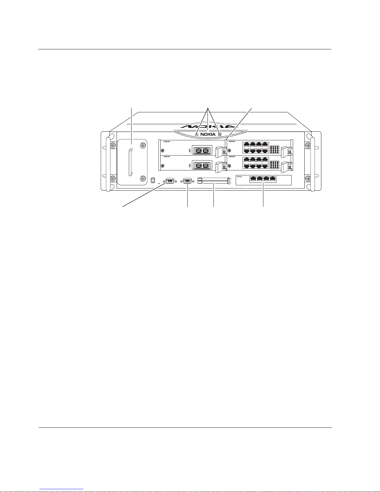
Figure 1 shows the component locations for IP2255 appliances.
Figure 1 Component Locations Front View
Fan tray System status LEDs
SLOT 1
10Base-SR X2
A
L
10Base-SR X2
A
L
SLOT 2
CONSOLE AUX PCMCIA
RESET
Network interface cards (4)
SLOT 3
1357
10/100 BaseT
10/100 BaseT
2468
1357
2468
SLOT 4
10/100/1000BaseT
1357
L
A
L
A
2468
1357
L
A
L
A
2468
SLOT 5
1234
IP2255
00010
Console port
Serial (AUX) port
PC-card slots
10/100/1000 Ethernet
management ports
The flash memory in the internal compact-flash slot provides the primary
application and operating system storage.
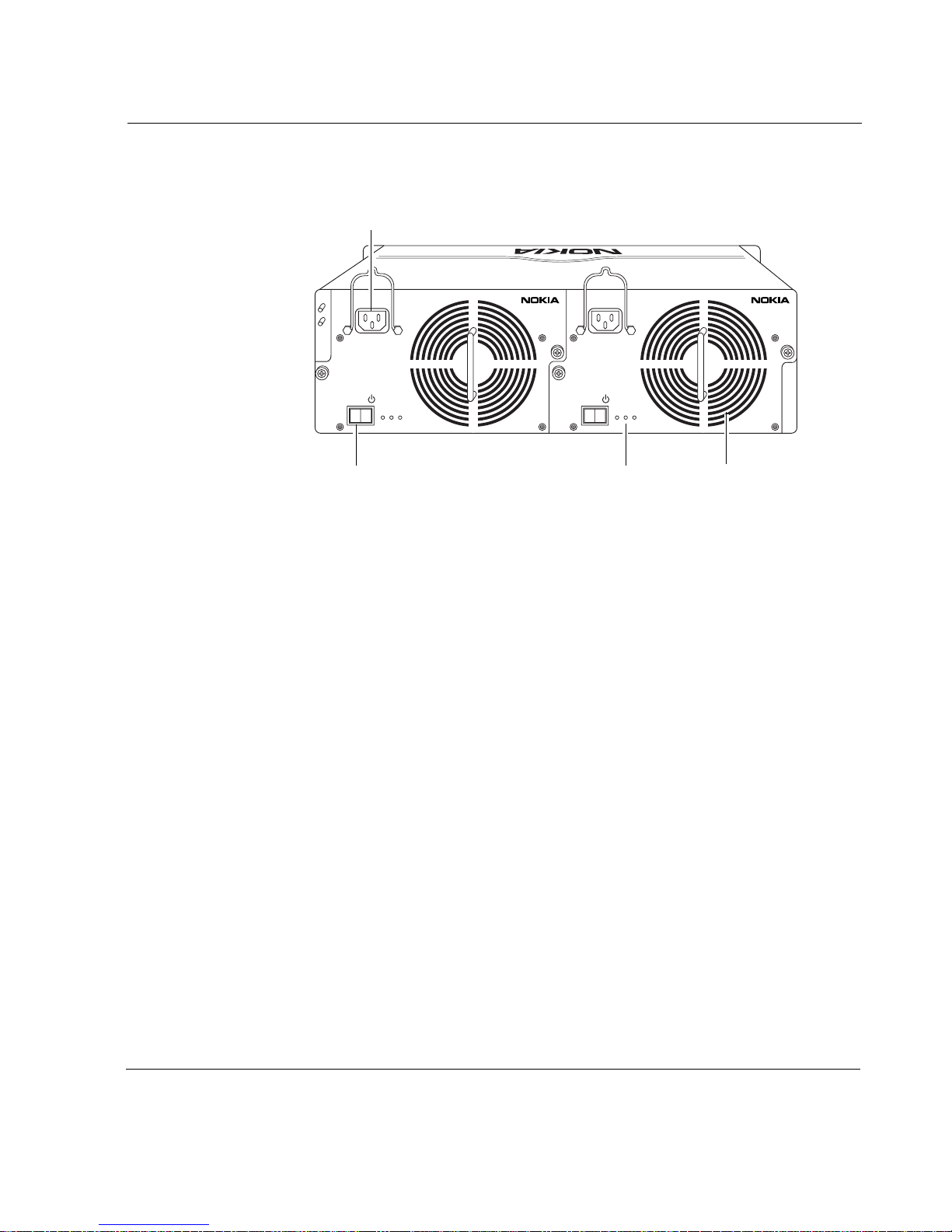
The power supplies are located at the back of the IP2255 appliance, as shown
in Figure 2.
22 Nokia IP2255 Security Platform Installation Guide
Nokia IP2255 Appliance Overview
Figure 2 Dual Power Supplies Location Rear View
Power cord receptacle
PWROKFAULT OVR
TEMP
Power switch
Ethernet Management Ports
The Ethernet management ports support 10-Mbps and 100-Mbps link speeds
and are located in the external cPCI slot.
The Ethernet management ports on IP2255 appliances are designed to be used
for the following purposes:
Managing the platform
Firewall synchronization traffic
IP cluster protocol traffic
Connection to a log server
The Nokia IP2255 appliance management ports are not suitable for
forwarding production data traffic. Do not use them for this purpose.
PWROKFAULT OVR
TEMP
00034
Status LEDs Power supply fan
Nokia recommends that you configure one port as the primary management
interface and a second port as the backup management interface.
Nokia IP2255 Security Platform Installation Guide 23
1
Overview
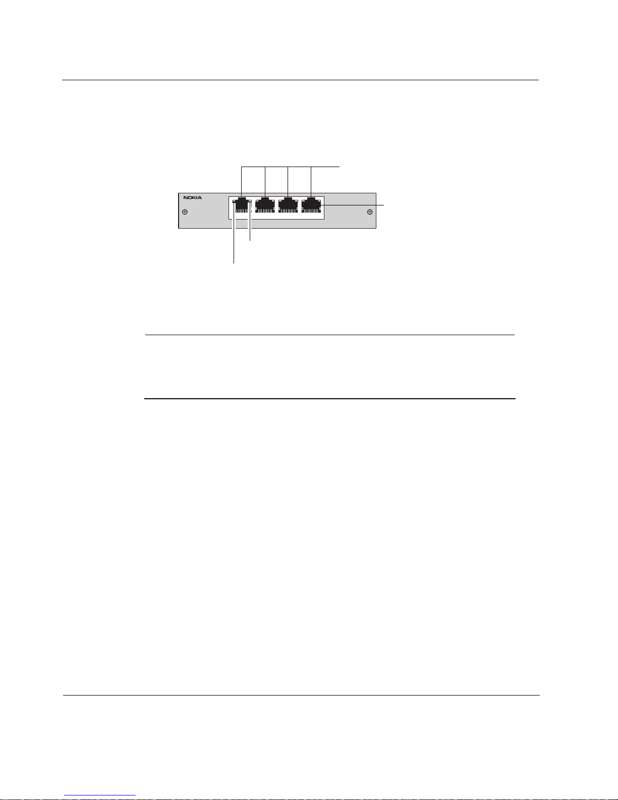
Figure 3 shows the details of the Ethernet management ports and LEDs.
Figure 3 Ethernet Management Port Details
Ports 1 trough 4
10/100/1000BaseT
1234
Link LED (yellow for 10/100, and green for 1000 Mbps)
Activity LED (yellow)
The physical names of the Ethernet management ports are eth-s5p1, eth-s5p2,
eth-s5p3, and eth-s5p4.
Note
For IP2255 appliances, Nokia recommends the use of shielded twistedpair cables and connectors for best Electromagnetic Interference and
Immunity performance.
Nokia Network Interface Cards
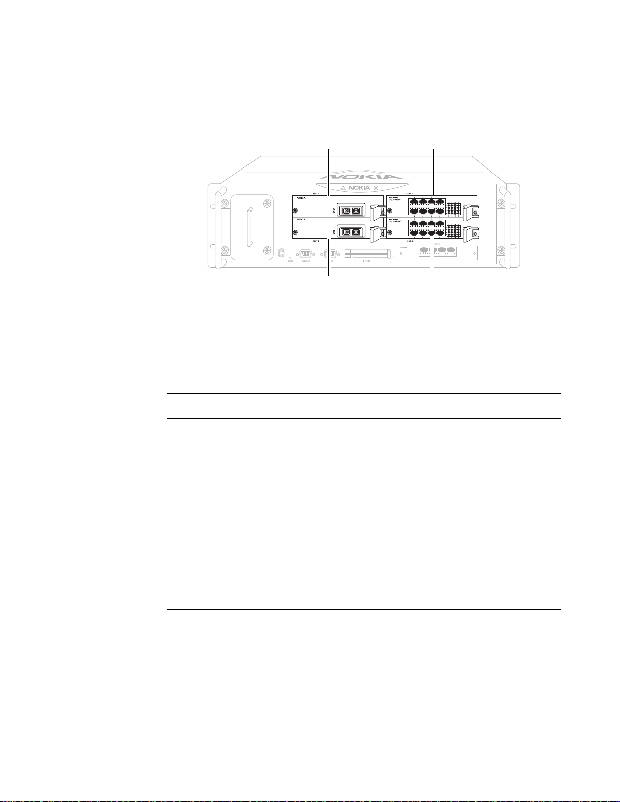
The Nokia IP2255 appliances have four network interface card (NIC) slots.
Each slot can accommodate one NIC. The NICs interface with the ADP
subsystem. Figure 4 shows the slot numbers for the NIC slots.
RJ-45 connectors
00157
24 Nokia IP2255 Security Platform Installation Guide
Nokia IP2255 Appliance Overview
Figure 4 Slot Numbers for Network Interface Cards
Slot 1
Slot 3
10Base-SR X2
10Base-SR X2
A
L
A
L
Slot 2
10/100/1000BaseT
1234
Slot 4
IP2255
00048
Slot 5 contains the cPCI Ethernet management ports and does not connect to
the ADP subsystem.
Nokia IP2255 appliances support the ADP format network interface cards
listed in Table 2.
Table 2 NICs Available for the Network Interface Card Slots
ADP format NIC For details, see...
Two-port copper Gigabit Ethernet
NIC
Two-port fiber-optic Gigabit
Ethernet NIC
“Two-Port and Four-Port Copper Gigabit
Ethernet NIC” on page 64
“Two-Port and Four-Port Fiber-Optic Gigabit
Ethernet NIC” on page 67
Eight-port 10/100 Ethernet NIC “Eight-Port 10/100 Ethernet NIC” on page 60
One-port fiber-optic 10 Gigabit
Ethernet NIC
Nokia encryption accelerator card “Installing, Replacing, and Configuring the
Nokia IP2255 Security Platform Installation Guide 25
“Fiber-Optic 10 Gigabit Ethernet NIC
Features” on page 69
Nokia Encryption Accelerator Card” on
page 73

1
Overview
Note
Nokia products support network interface cards purchased from Nokia or
Nokia-approved resellers only. The Nokia Global Support Services group
can provide support only for Nokia products that use Nokia-approved
accessories. For sales or reseller information, contact a Nokia service
provider listed in the “Nokia Contact Information” on page 3.
Console Port
Use the built-in console port, shown in Figure 1 on page 22, to supply
information that makes the appliance available on the network. Figure 5
provides pin assignment information for console connections.
26 Nokia IP2255 Security Platform Installation Guide
Nokia IP2255 Appliance Overview
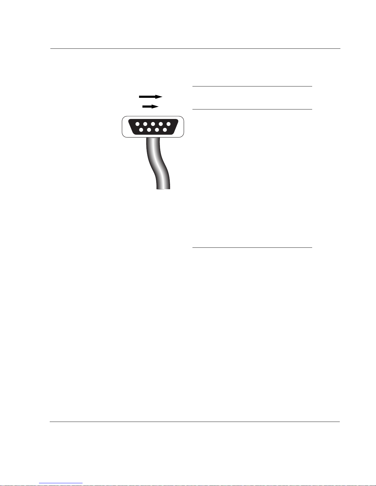
Figure 5 Pin Assignments for Console Connection
1
69
5
00156
Pin Assignment Input/Output
1 DCD Input
2 RXD Input
3 TXD Output
4 DTR Output
5GND
6 DSR Input
7 RTS Output
8 CTS Input
9 DTR Output
Serial Port
Use the built-in serial (AUX) port, shown in Figure 1 on page 22 to establish a
modem connection to manage the appliance. Figure 6 provides pin-
assignment information for modem connections.
Nokia IP2255 Security Platform Installation Guide 27
1
Overview
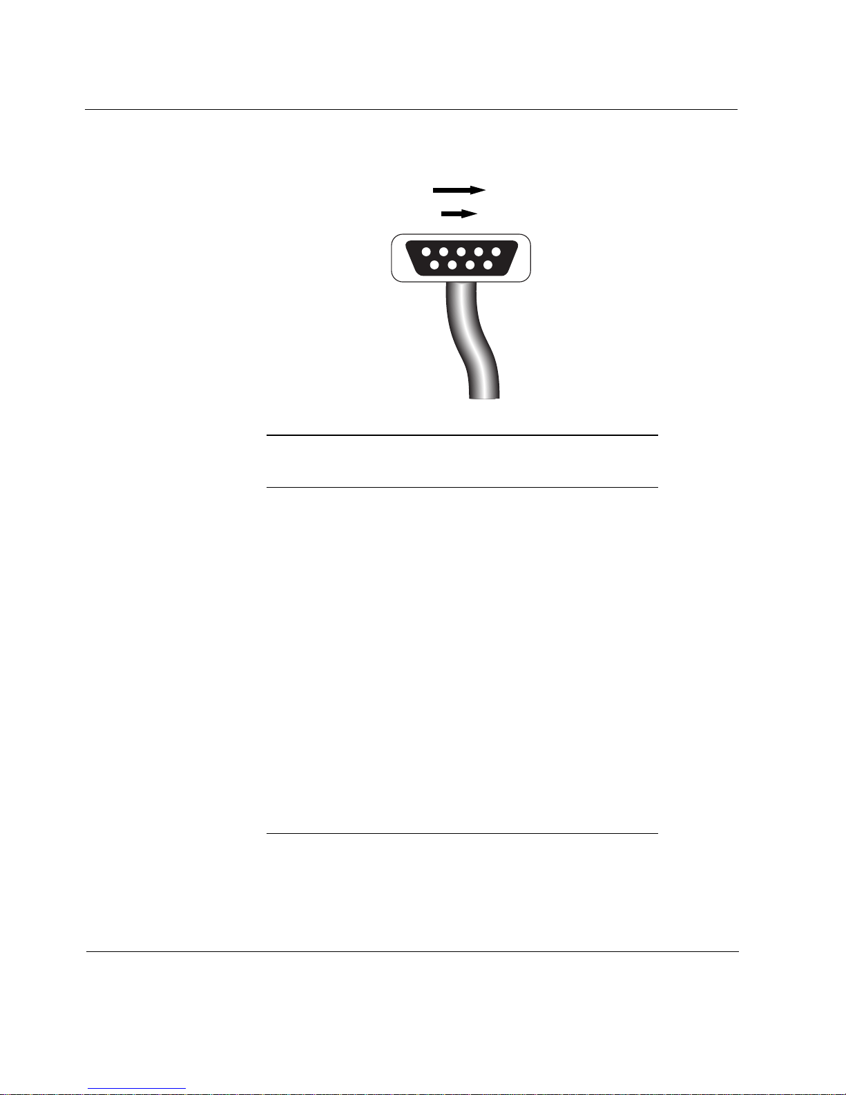
Figure 6 Pin Assignments for Modem Connection
1
5
69
00156
Pin
Input or
output
To DB25
cable out
To DB9
cable out
1 (DCD) Input 8 (DCD) 7 (RTS)
8 (CTS)
2 (RXD) Input 2 (TXD) 3 (TXD)
3 (TXD) Output 3 (RXD) 2 (RXD
4 (DTR) Output 20 (DTR) 6 (DSR)
9 (RI)
5 (GND) 7 (GND) 5 (GND)
6 (DSR) Input 6 (DSR) 4 (DTR)
7 (RTS) Output 4 (RTS) 1 (DCD)
8 (CTS) Input 5 (CTS) 1 (DCD)
9 (RI) Output 22 (RI) 4 (DTR)
28 Nokia IP2255 Security Platform Installation Guide
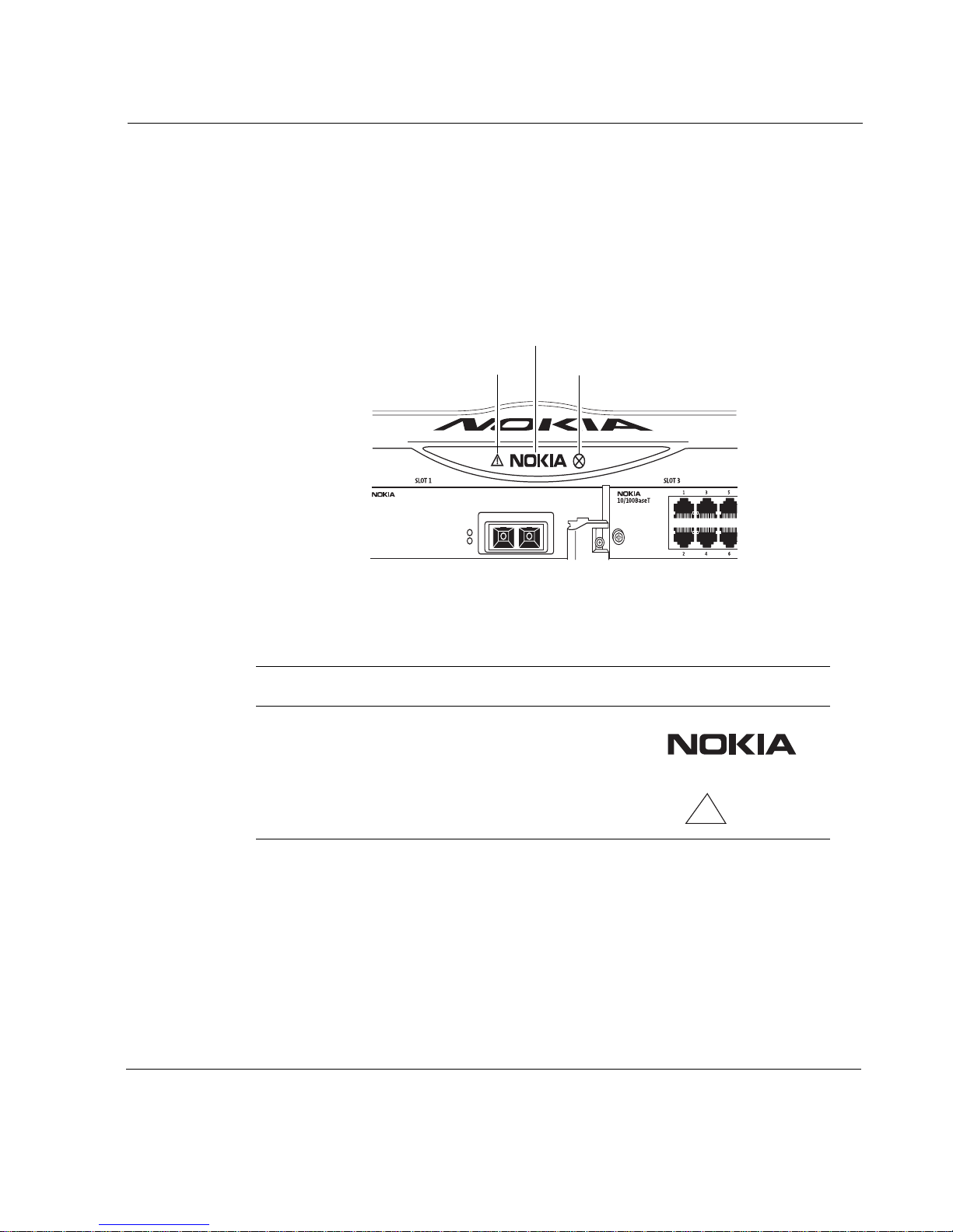
System Status LEDs
You can monitor the basic operation of the your appliance by checking the
system status LEDs. The system status LEDs are located on the front panel of
the appliance, as shown in Figure 7.
Figure 7 System Status LEDs
Nokia IP2255 Appliance Overview
Power and status
10Base-SR X2
Voltage
A
L
Fan unit and power supply
00025
Table 3 shows the system status LEDs and describes their meaning.
Table 3 System Status LEDs
Status indicator Meaning Symbol
Solid blue Power on
Solid yellow Appliance is experiencing an
internal voltage problem.
!
Nokia IP2255 Security Platform Installation Guide 29
1
Overview
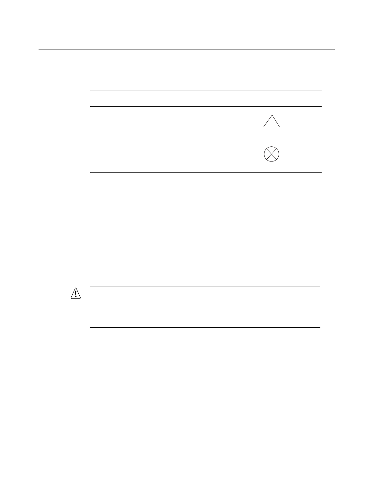
Table 3 shows the system status LEDs and describes their meaning.
Table 3 System Status LEDs
Status indicator Meaning Symbol
Blinking yellow Appliance is experiencing a
temperature problem.
Solid red One or more fans are not
operating properly or one of the
connected power supplies is
experiencing a problem.
!
The location and meaning of the status LEDs for the installed NICs is
described in Chapter 4, “Connecting to the Network Interface Cards.”
Fan Unit
The Nokia IP2255 appliance fan unit is a single unit made up of four
individual fans to provide the air flow required to maintain a proper operating
temperature. The fan unit provides N + 1 cooling, so it can provide proper
airflow even if an individual fan fails.
Caution
If an individual fan fails, replace the fan unit as soon as possible. For
information about how to replace a failed fan unit, see “Replacing the
Fan Unit” on page 96.
The system status LEDs on the front panel of the appliance show the status of
the fan unit. For more information about the system status LEDs, see “System
Status LEDs” on page 29.
30 Nokia IP2255 Security Platform Installation Guide
 Loading...