

Nokia IP200, IP260, IP265 Installation Manual
Nokia IP200 Series
Security Platform
Installation Guide
Part No. N451435002 Rev A
Published January 2006

COPYRIGHT
©2006 Nokia. All rights reserved.
Rights reserved under the copyright laws of the United States.
RESTRICTED RIGHTS LEGEND
Use, duplication, or disclosure by the United States Government is subject to restrictions as set
forth in subparagraph (c)(1)(ii) of the Rights in Technical Data and Computer Software clause at
DFARS 252.227-7013.
Notwithstanding any other license agreement that may pertain to, or accompany the delivery of,
this computer software, the rights of the United States Government regarding its use,
reproduction, and disclosure are as set forth in the Commercial Computer Software-Restricted
Rights clause at FAR52.227-19.
IMPORTANT NOTE TO USERS
This software and hardware is provided by Nokia Inc. as is and any express or implied
warranties, including, but not limited to, implied warranties of merchantability and fitness for a
particular purpose are disclaimed. In no event shall Nokia, or its affiliates, subsidiaries or
suppliers be liable for any direct, indirect, incidental, special, exemplary, or consequential
damages (including, but not limited to, procurement of substitute goods or services; loss of use,
data, or profits; or business interruption) however caused and on any theory of liability, whether in
contract, strict liability, or tort (including negligence or otherwise) arising in any way out of the use
of this software, even if advised of the possibility of such damage.
Nokia reserves the right to make changes without further notice to any products herein.
TRADEMARKS
Nokia is a registered trademark of Nokia Corporation. Other products mentioned in this document
are trademarks or registered trademarks of their respective holders.
060101
2 Nokia IP200 Series Security Platform Installation Guide

Nokia Contact Information
Corporate Headquarters
Web Site http://www.nokia.com
Telephone 1-888-477-4566 or
1-650-625-2000
Fax 1-650-691-2170
Mail
Address
Regional Contact Information
Americas Nokia Inc.
Europe,
Middle East,
and Africa
Asia-Pacific 438B Alexandra Road
Nokia Customer Support
Web Site: https://support.nokia.com/
Email: tac.support@nokia.com
Nokia Inc.
313 Fairchild Drive
Mountain View, California
94043-2215 USA
313 Fairchild Drive
Mountain View, CA 94043-2215
USA
Nokia House, Summit Avenue
Southwood, Farnborough
Hampshire GU14 ONG UK
#07-00 Alexandra Technopark
Singapore 119968
Tel: 1-877-997-9199
Outside USA and Canada: +1 512-437-7089
email: info.ipnetworking_americas@nokia.com
Tel: UK: +44 161 601 8908
Tel: France: +33 170 708 166
email: info.ipnetworking_emea@nokia.com
Tel: +65 6588 3364
email: info.ipnetworking_apac@nokia.com
Americas Europe
Voice: 1-888-361-5030 or
Fax: 1-613-271-8782 Fax: +44 (0) 125-286-5666
Asia-Pacific
Voice: +65-67232999
Fax: +65-67232897
Nokia IP200 Series Security Platform Installation Guide 3
Voice: +44 (0) 125-286-8900
1-613-271-6721
050602

4 Nokia IP200 Series Security Platform Installation Guide

Contents
About this Guide . . . . . . . . . . . . . . . . . . . . . . . . . . . . . . . . . . . . . .13
In This Guide . . . . . . . . . . . . . . . . . . . . . . . . . . . . . . . . . . . . . . . . . 13
Conventions This Guide Uses . . . . . . . . . . . . . . . . . . . . . . . . . . . . 14
Notices . . . . . . . . . . . . . . . . . . . . . . . . . . . . . . . . . . . . . . . . . . . . 14
Command-Line Conventions. . . . . . . . . . . . . . . . . . . . . . . . . . . . 15
Text Conventions . . . . . . . . . . . . . . . . . . . . . . . . . . . . . . . . . . . . 16
Related Documentation . . . . . . . . . . . . . . . . . . . . . . . . . . . . . . . . . 17
1 Overview . . . . . . . . . . . . . . . . . . . . . . . . . . . . . . . . . . . . . . . . . . . 19
About the Nokia IP200 Security Platform. . . . . . . . . . . . . . . . . . . . 19
Nokia IP200 Security Platform Appliance Overview. . . . . . . . . . . . 20
Built-in Ethernet Ports . . . . . . . . . . . . . . . . . . . . . . . . . . . . . . . . . 21
Console and Serial (AUX) Ports . . . . . . . . . . . . . . . . . . . . . . . . . 22
System Status LEDs . . . . . . . . . . . . . . . . . . . . . . . . . . . . . . . . . . 24
Site Requirements . . . . . . . . . . . . . . . . . . . . . . . . . . . . . . . . . . . . . 26
Product Disposal . . . . . . . . . . . . . . . . . . . . . . . . . . . . . . . . . . . . . . 26
Safety Warnings and Cautions. . . . . . . . . . . . . . . . . . . . . . . . . . . . 27
Managing IP200 Security Platform Appliances . . . . . . . . . . . . . . . 28
2 Installing a Nokia IP200 Security Appliance . . . . . . . . . . . . . . . 31
Rack Mounting a Single Nokia IP200 Appliance. . . . . . . . . . . . . 31
Rack Mounting Two Nokia IP200 Appliances Side by Side . . . . 33
Nokia IP200 Series Security Platform Installation Guide 5

3 Performing the Initial Configuration . . . . . . . . . . . . . . . . . . . . . 39
Using a Console Connection . . . . . . . . . . . . . . . . . . . . . . . . . . . . . 40
Connecting Power and Turning the Power On. . . . . . . . . . . . . . . . 41
Performing the Initial Configuration . . . . . . . . . . . . . . . . . . . . . . . . 43
Connecting Network Interfaces . . . . . . . . . . . . . . . . . . . . . . . . . . . 45
Using Nokia Network Voyager to Manage Your Appliance . . . . . . 46
Viewing Nokia IPSO Documentation by Using
Nokia Network Voyager . . . . . . . . . . . . . . . . . . . . . . . . . . . . . . 47
Using the Command-Line Interface to Manage Your Appliance . . 48
Using Nokia Horizon Manager. . . . . . . . . . . . . . . . . . . . . . . . . . . . 49
4 Connecting to the Ethernet Ports . . . . . . . . . . . . . . . . . . . . . . . 51
Built-In Four-Port 10/100 Ethernet Interface . . . . . . . . . . . . . . . . . 51
Ethernet Features . . . . . . . . . . . . . . . . . . . . . . . . . . . . . . . . . . . . 52
Connecting to Ethernet Ports . . . . . . . . . . . . . . . . . . . . . . . . . . . 52
5 Configuring and Activating Encryption Acceleration . . . . . . . 55
Configuring and Activating Nokia Encryption Acceleration . . . . . . 55
Configuring Software to Use Hardware Acceleration. . . . . . . . . . . 56
6 Installing Flash-Memory PC Cards . . . . . . . . . . . . . . . . . . . . . . 57
Before You Begin. . . . . . . . . . . . . . . . . . . . . . . . . . . . . . . . . . . . . . 58
Installing a Flash-Memory PC Card. . . . . . . . . . . . . . . . . . . . . . . . 59
Storing System Logs on the Flash-Memory PC Card . . . . . . . . . . 59
Transferring Files with the Flash-Memory PC Card. . . . . . . . . . . . 61
6 Nokia IP200 Series Security Platform Installation Guide

7 Using the Nokia IPSO Boot Manager . . . . . . . . . . . . . . . . . . . . . 63
Starting the Boot-Manager Command-Line Interface. . . . . . . . . . . 65
Stopping the System from the Boot Manager . . . . . . . . . . . . . . . . 66
Using the Boot Manager to Boot the System. . . . . . . . . . . . . . . . . 66
Setting and Viewing Boot-Manager Variables . . . . . . . . . . . . . . . . 67
Viewing Other System Information . . . . . . . . . . . . . . . . . . . . . . . 71
Protecting the Boot Manager with a Password . . . . . . . . . . . . . . . 72
Resetting the Admin Password . . . . . . . . . . . . . . . . . . . . . . . . . . . 75
Reinstalling or Upgrading the Boot Manager . . . . . . . . . . . . . . . . . 76
Troubleshooting . . . . . . . . . . . . . . . . . . . . . . . . . . . . . . . . . . . . . . . 78
8 Troubleshooting . . . . . . . . . . . . . . . . . . . . . . . . . . . . . . . . . . . . . 81
General Troubleshooting Information. . . . . . . . . . . . . . . . . . . . . . . 81
A Technical Specifications . . . . . . . . . . . . . . . . . . . . . . . . . . . . . . 87
Physical Dimensions . . . . . . . . . . . . . . . . . . . . . . . . . . . . . . . . . . . 87
Space Requirements . . . . . . . . . . . . . . . . . . . . . . . . . . . . . . . . . . . 87
Other Specifications. . . . . . . . . . . . . . . . . . . . . . . . . . . . . . . . . . . . 88
Appliance Interfaces. . . . . . . . . . . . . . . . . . . . . . . . . . . . . . . . . . . . 89
B Compliance Information . . . . . . . . . . . . . . . . . . . . . . . . . . . . . . . 91
Declaration of Conformity. . . . . . . . . . . . . . . . . . . . . . . . . . . . . . . . 91
Compliance Statements. . . . . . . . . . . . . . . . . . . . . . . . . . . . . . . . . 93
FCC Notice (US) . . . . . . . . . . . . . . . . . . . . . . . . . . . . . . . . . . . . . . 94
Index . . . . . . . . . . . . . . . . . . . . . . . . . . . . . . . . . . . . . . . . . . . . . . . 97
Nokia IP200 Series Security Platform Installation Guide 7

8 Nokia IP200 Series Security Platform Installation Guide

Tables
Table 1 Command-Line Conventions . . . . . . . . . . . . . . . . . . . . . 15
Table 2 Text Conventions . . . . . . . . . . . . . . . . . . . . . . . . . . . . . . 16
Table 3 Pin Assignments for DB9 and DB25 Interface Cables . . 24
Table 4 Appliance Status LEDs . . . . . . . . . . . . . . . . . . . . . . . . . . 25
Table 5 Boot Manager Variables . . . . . . . . . . . . . . . . . . . . . . . . . 67
Table 6 Boot Flags . . . . . . . . . . . . . . . . . . . . . . . . . . . . . . . . . . . 68
Nokia IP200 Series Security Platform Installation Guide 9

10 Nokia IP200 Series Security Platform Installation Guide

Figures
Figure 1 Component Locations Front View . . . . . . . . . . . . . . . . . 20
Figure 2 Component Locations Rear View . . . . . . . . . . . . . . . . . 21
Figure 3 Built-In Ethernet Interface Front Panel Details . . . . . . . 21
Figure 4 Pin Assignments for Console and AUX Connections . . 23
Figure 5 Appliance Status LEDs . . . . . . . . . . . . . . . . . . . . . . . . . 25
Figure 6 Installing the Mounting Brackets . . . . . . . . . . . . . . . . . . 32
Figure 7 Single Appliance Installation . . . . . . . . . . . . . . . . . . . . . 33
Figure 8 Power Switch Location . . . . . . . . . . . . . . . . . . . . . . . . . 42
Figure 9 Nokia Network Voyager Reference Access Points . . . . 47
Figure 10 Output Connector for the Ethernet Cable . . . . . . . . . . 53
Figure 11 Ethernet Crossover Cable Pin Connections . . . . . . . . 54
Figure 12 Inserting a Flash-Memory PC Card . . . . . . . . . . . . . . . 58
Nokia IP200 Series Security Platform Installation Guide 11

12 Nokia IP200 Series Security Platform Installation Guide

About this Guide
This guide provides information for the installation and use of the Nokia
IP200 Series security platform, which consists of the Nokia IP260 and Nokia
IP265 appliances. Installation and maintenance should be performed by
experienced technicians or Nokia-approved service providers only.
This preface provides the following information:
In This Guide
Conventions This Guide Uses
Related Documentation
In This Guide
This guide is organized into the following chapters and appendixes:
Chapter 1, “Overview” presents a general overview of the Nokia IP200
Security Platform.
Chapter 2, “Installing a Nokia IP200 Security Appliance” explains how to
rack mount the appliance and how to physically connect it to a network
and power.
Chapter 3, “Performing the Initial Configuration” explains how to make
the appliance available on the network.
Chapter 4, “Connecting to the Ethernet Ports” describes how to connect to
the supported Ethernet ports.
Nokia IP200 Series Security Platform Installation Guide 13
Chapter 5, “Configuring and Activating Encryption Acceleration”
describes how to configure and activate the built-in encryption
acceleration feature.
Chapter 6, “Installing Flash-Memory PC Cards” explains how to install or
replace ATA flash-memory PC cards in your IP200 appliance.
Chapter 7, “Using the Nokia IPSO Boot Manager” explains how to use
the boot manager, which is part of the Nokia IPSO software.
Chapter 8, “Troubleshooting” discusses problems you might encounter
and proposes solutions to these problems.
Appendix A, “Technical Specifications” gives technical specifications
such as interface characteristics.
Appendix B, “Compliance Information” includes compliance and
regulatory information.
Conventions This Guide Uses
The following sections describe the conventions this guide uses, including
notices, text conventions, and command-line conventions.
Notices
Warning
Warnings advise the user that bodily injury might occur because of a
physical hazard.
Caution
Cautions indicate potential equipment damage, equipment
malfunction, loss of performance, loss of data, or interruption of
service.
14 Nokia IP200 Series Security Platform Installation Guide

Note
Notes provide information of special interest or recommendations.
Command-Line Conventions
This section defines the elements of commands that are available in Nokia
Internet Communications products. You might encounter one or more of the
following elements in a command-line path.
Table 1 Command-Line Conventions
Convention Description
command A user-generated instruction typically sent using a console
or terminal. The command statement and its associated
syntax must be entered exactly as shown in lowercase
letters.
Conventions This Guide Uses
italics Indicates a variable in a command that you must supply. For
example:
delete interface if_name
Supply an interface name in place of the variable. For
example:
delete interface nic1
angle brackets < > Indicates arguments for which you must supply a value:
retry-limit <1–100>
Supply a value. For example:
retry-limit 60
Nokia IP200 Series Security Platform Installation Guide 15

Table 1 Command-Line Conventions (continued)
Convention Description
-flag A flag is usually an abbreviation for a function, menu, or
.ext A filename extension, such as .ext, might follow a variable
( . , ; + * - / ) Punctuation and mathematical notations are literal symbols
Text Conventions
Table 2 describes the text conventions this guide uses.
Table 2 Text Conventions
option name, or for a compiler or preprocessor argument.
You must enter a flag exactly as shown, including the
preceding hyphen.
that represents a filename. Type this extension exactly as
shown, immediately after the name of the file. The extension
might be optional in certain products.
that you must enter exactly as shown.
Convention Description
monospace font
Indicates command syntax, or represents computer or
screen output, for example:
Log error 12453
bold monospace font Indicates text you enter or type, for example:
# configure nat
Key names Keys that you press simultaneously are linked by a
plus sign (+):
Press Ctrl + Alt + Del.
Menu commands Menu commands are separated by a greater than
sign (>):
Choose File > Open.
16 Nokia IP200 Series Security Platform Installation Guide

Related Documentation
Table 2 Text Conventions (continued)
Convention Description
The words enter and type Enter indicates you type something and then press
the Return or Enter key.
Do not press the Return or Enter key when an
instruction says type.
Italics
Related Documentation
You can find this guide in PDF on the Nokia support We b site (https://
support.nokia.com/).
In addition to this guide, documentation for this product includes the
following:
Getting Started Guide and Release Notes for the version of IPSO you are
using
Nokia Network Voyager Reference Guide for the version of IPSO you are
using
CLI Reference Guide for the version of IPSO you are using
Nokia Network Voyager inline help
• Emphasizes a point or denotes new terms at the
place where they are defined in the text.
• Indicates an external book title reference.
• Indicates a variable in a command:
delete interface
if_name
You can access the Nokia Voyager inline help, the Nokia Network Voyager
Reference Guide, and the CLI Reference Guide for the version of IPSO you
are using from the Nokia Voyager application.
Check Point documentation is available from the Check Point Web site at
http://www.checkpoint.com. You can also order Check Point documentation
from Nokia or download it from the Nokia support site at https://
support.nokia.com.
Nokia IP200 Series Security Platform Installation Guide 17

18 Nokia IP200 Series Security Platform Installation Guide

1 Overview
This chapter provides an overview of the Nokia IP200 Security Platform and
the requirements for using the IP200 appliances. The following topics are
covered:
About the Nokia IP200 Security Platform on page 19
Nokia IP200 Security Platform Appliance Overview on page 20
Site Requirements on page 26
Safety Warnings and Cautions on page 27
Product Disposal on page 26
Managing IP200 Security Platform Appliances on page 28
About the Nokia IP200 Security Platform
The Nokia IP200 Security Platform combines the power of Nokia IPSO
software with your choice of firewall and VPN applications.
The IP200 platform provides built-in hardware-based encryption acceleration.
The IP200 appliances are ideally suited for growing companies and satellite
offices that want high-performance IP routing combined with the
industry-leading Check Point VPN-1/FireWall-1 enterprise security suite. The
small size of the IP200 appliances makes them ideal for installations that need
to conserve space.
Nokia IP200 Series Security Platform Installation Guide 19
1 Overview
As network devices, the IP200 appliances support a comprehensive suite of
IP-routing functions and protocols, including RIPv1/RIPv2, IGRP, OSPF and
BGP4 for unicast traffic, and DVMRP for multicast traffic. The integrated
router functionality eliminates the need for separate intranet and access
routers in security applications.
For more information and technical specifications, see “Technical
Specifications” on page 87.
Nokia IP200 Security Platform Appliance
Overview
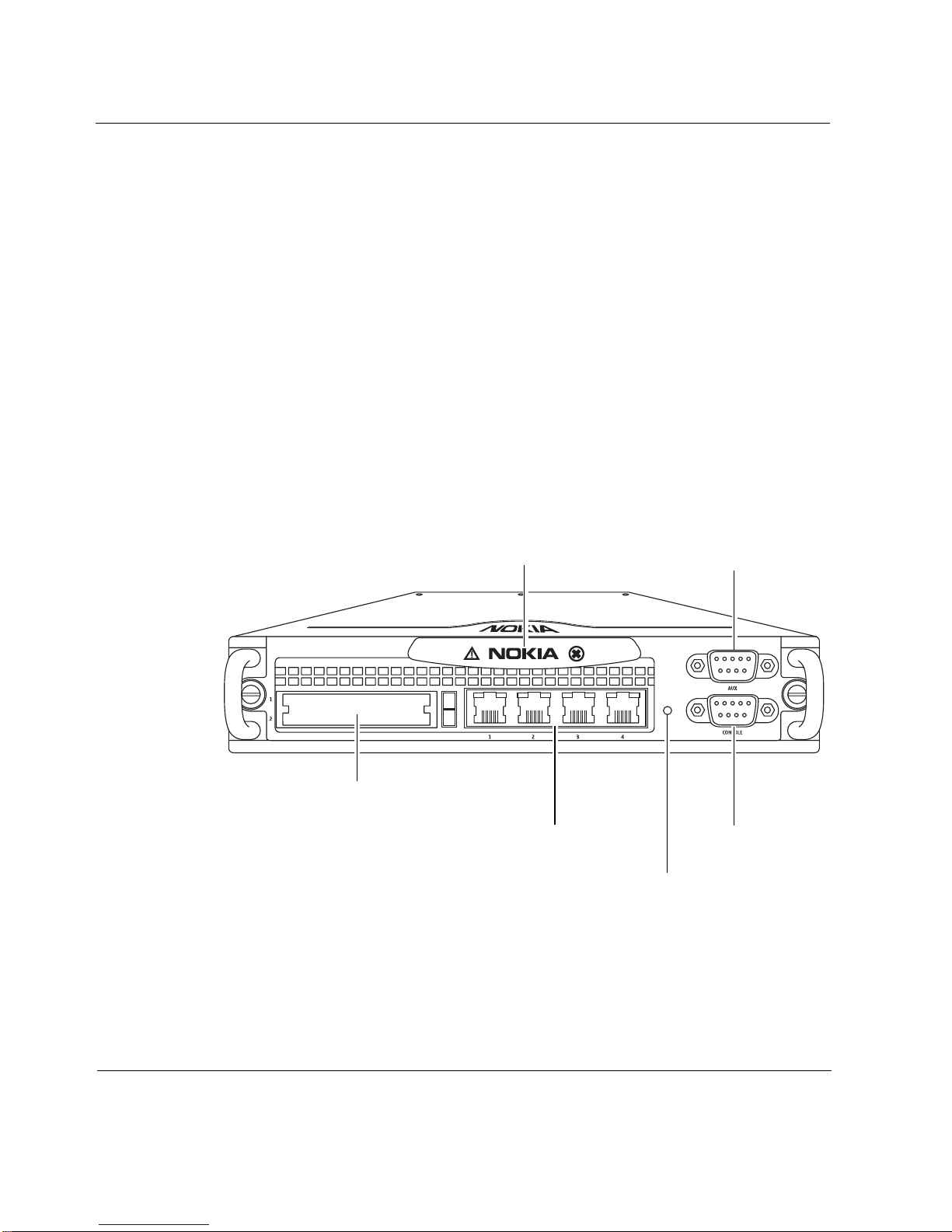
The following figures show comp onent l ocations for Nokia IP 200 appliances.
Figure 1 Component Locations Front View
IP260
PCMCIA slots
Status LEDs
Built-in Ethernet ports
(10/100 Mbps)
Auxiliary (AUX) port
00024
Console port
Reset switch
20 Nokia IP200 Series Security Platform Installation Guide
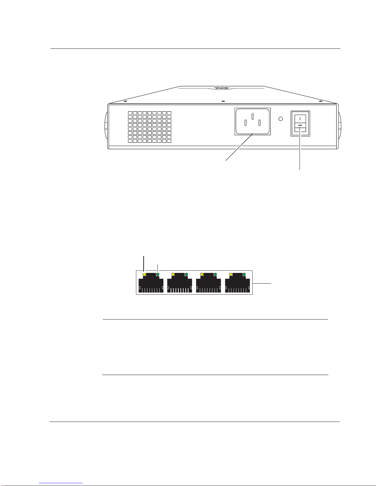
Figure 2 Component Locations Rear View
Built-in Ethernet Ports
Nokia IP200 Security Platform Appliance Overview
00321
Power plug
Power switch
Figure 3 shows the layout of the built-in Ethernet ports and LEDs.
Figure 3 Built-In Ethernet Interface Front Panel Details
Activity LED (yellow)
Link LED (green)
RJ-45 connectors
00120
Note
Nokia products support NICs purchased from Nokia Corporation or
Nokia-approved resellers only. The Nokia Global Support Services group
can provide support only for Nokia products that use Nokia-approved
accessories. For sales or reseller information, contact a Nokia service
provider listed in the “Nokia Contact Information” on page 3.
Nokia IP200 Series Security Platform Installation Guide 21
1 Overview
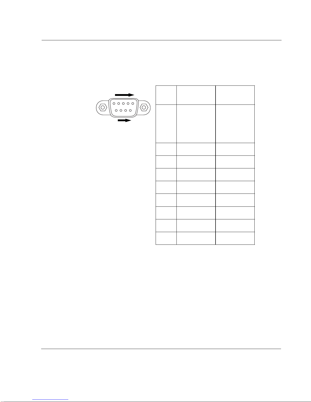
Console and Serial (AUX) Ports
Use the built-in console port to supply the information that makes the
appliance available on the network. Use the built-in serial (AUX) port for
RS232-compliant equipment you are using with your appliance; for example,
as a modem connection for managing the appliance. Figure 4 provides pin
assignment information for console and serial connections.
Caution
Nokia recommends that you use the console cable that was
delivered with your appliance for your console connection.
Otherwise, ensure that the pin assignments for your cable match
those provided in this section.
Note
Although pin assignments are the same for console and serial
connections, they are used diff erently by the appliance. Ther efore, do not
use these two connectors interchangeably.
22 Nokia IP200 Series Security Platform Installation Guide
Nokia IP200 Security Platform Appliance Overview
Figure 4 Pin Assignments for Console and AUX Connections
1
5
69
00460
Input or
Pin# Assignment
1DCD
output
Input
(AUX port
only; not used
by the console
port)
2RXD Input
3 TXD Output
4 DTR Output
5GND
6DSR Input
7 RTS Output
8CTS Input
9 not used
Nokia IP200 Series Security Platform Installation Guide 23

1 Overview
Table 3 shows how to match pins at the console or serial connector with
output pins on DB9 or DB25 cables you are using with terminal devices or
other appropriate equipment.
Table 3 Pin Assignments for DB9 and DB25 Interface Cables
Console or serial
pin and assignment
Shield (FG) Shield (FG) 1 (FG)
2 (RXD) 3 (TXD) 2 (TXD)
3 (TXD) 2 (RXD) 3 (RXD)
4 (DTR) 6 (DSR) 6 (DSR)
5 (SG) 5 (SG) 7 (SG)
6 (DSR) 4 (DTR) 20 (DTR)
7 (RTS) 8 (CTS) 5 (CTS)
8 (CTS) 7 (RTS) 4 (RTS)
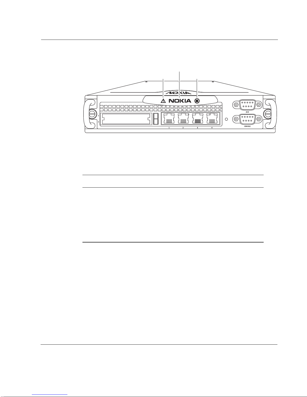
System Status LEDs
You can monitor the basic operation of Nokia IP200 appliances by checking
their status LEDs. The system status LEDs are located on the front panel of
the appliance, as Figure 5 shows.
DB9 cable output pin and
assignment
DB25 cable output pin and
assignment
24 Nokia IP200 Series Security Platform Installation Guide
Nokia IP200 Security Platform Appliance Overview
Figure 5 Appliance Status LEDs
Power or Status
Caution
IP260
Critical
Figure 4 describes the status conditions for each of the LEDs for all
indications they might display.
Table 4 Appliance Status LEDs
00024
Indicator Color Description
Caution None (off)
Yellow (steady)
Normal
Initial boot flash activity
or
Internal voltage problem
Yellow (blinking)
Temperature fault
Nokia IP200 Series Security Platform Installation Guide 25

1 Overview
Figure 4 describes the status conditions for each of the LEDs for all
indications they might display.
Table 4 Appliance Status LEDs (continued)
Indicator Color Description
Power or
Status
Critical None (off)
None (off)
Blue
Red
For information about the built-in Ethernet interface LEDs, see “Built-in
Ethernet Ports” on page 21.
Site Requirements
Before you install a Nokia IP200 appliance, ensure that your computer room
or wiring closet conforms to the environmental specifications listed in
Appendix A, “Technical Specifications.”
Power off
Power on
Normal
One or more fans are defective.
or
No recognizable boot device with
a valid kernel found.
or
Kernel panic (followed in 20
seconds by CPU reset).
Product Disposal
At the end of its useful life, your appliance and all peripherals included with
it, including power cords and cables, must be disposed of in accordance with
all applicable national, state, and local laws and regulations. These devices
contain materials and components that must be disposed of properly.
26 Nokia IP200 Series Security Platform Installation Guide
Safety Warnings and Cautions
Therefore, to help prevent damage to the environment, Nokia encourages you
to dispose of these devices in an environmentally-friendly manner.
The following resources are available to you to help with equipment-disposal
decisions:
Many Nokia products are labeled with information about the materials
used in their manufacture that can help those who will process equipment
after you have disposed of it.
The Nokia web site (http://www.nokia.com) provides information about
our environmental programs and practices, which includes details about
materials used in manufacturing and end-of-life practices. You can also
find your product’ s Eco Declaration , which provides basic information o n
the environmental attributes of the product covering material use,
packaging, disassembly, and recycling.
Contact your local waste management agencies for guidelines specific to
your area.
The crossed-out wheeled bin means that within the European Union the product
must be taken to separate collection at the product end-of-life. This applies to your
device but also to any enhancements marked with this symbol. Do not dispose of
these products as unsorted municipal waste.
Safety Warnings and Cautions
Warning
To reduce the risk of fire, electric shock, and injury when you use
telephone equipment, follow basic safety precautions. Do not use the
product near water.
Nokia IP200 Series Security Platform Installation Guide 27
1 Overview
Caution
Do not place objects over the ventilation holes on the IP200
appliance. The components might overheat and become damaged.
Caution
For IP200 appliances intended for shipment outside of the United
States, the power cord might not be included. If a power cord is not
provided, use a power cord rated at 6A, 250V, maximum 15 feet
long, made of HAR cordage and IEC fittings approved by the country
of end use.
Managing IP200 Security Platform Appliances
You can manage Nokia IP200 appliances by using one of the following
interfaces:
Nokia Network Voyager—an SSL-secured, Web-based element
management interface to Nokia IP security platforms. Network V oyager is
preinstalled on the IP200 appliance and enabled through the IPSO
operating system. With Network Voyager, you can manage, monitor, and
configure the IP200 appliance from any authorized location within the
network by using a standard Web browser.
For information about how to access Network Voyager and the related
reference materials, see “Using Nokia Network Voyager to Manage Your
Appliance” on page 46.
The Nokia IPSO command-line interface (CLI)—an SSHv2-secured
interface that
from the
enables you to configure Nokia IP security platforms
command line. Everything that you can accomplish with Nokia
Voyager—to manage and configure the IP200 appliance—you can also do
with the CLI.
28 Nokia IP200 Series Security Platform Installation Guide

Managing IP200 Security Platform Appliances
For information about how to access the CLI, see the Nokia CLI
Reference Guide for the version of IPSO you are using.
Nokia Horizon Manager—a secure GUI-based software image
management application. With Horizon Manager , you can securely install
and upgrade the Nokia proprietary IPSO operating system, plus hardware
and third-party applications such as Check Point FireWall-1. Horizon
Manager can perform installations and upgrades on up to 2,500 Nokia IP
security platforms, offering administrators the most rapid and dependable
upgrade to Check Point NG.
For information about how to obtain Horizon Manager, see “Nokia
Contact Information” on page 3.
Nokia IP200 Series Security Platform Installation Guide 29

1 Overview
30 Nokia IP200 Series Security Platform Installation Guide
 Loading...