

Nokia IP1220 - Security, IP1260 Appliance Installation Manual

Part No. N450000536 Rev 001
Published June 2008
IP1220 and IP1260 Security
Platforms Installation Guide

2 IP1220 and IP1260 Security Platforms Installation Guide
COPYRIGHT
©2008 Nokia. All rights reserved.
Rights reserved under the copyright laws of the United States.
RESTRICTED RIGHTS LEGEND
Use, duplication, or disclosure by the United States Government is subject to restrictions as set forth in subparagraph
(c)(1)(ii) of the Rights in Technical Data and Computer Software clause at DFARS 252.227-7013.
Notwithstanding any other license agreement that may pertain to, or accompany the delivery of, this computer software,
the rights of the United States Government regarding its use, reproduction, and disclosure are as set forth in the
Commercial Computer Software-Restricted Rights clause at FAR 52.227-19.
IMPORTANT NOTE TO USERS
This software and hardware is provided by Nokia Inc. as is and any express or implied warranties, including, but not
limited to, implied warranties of merchantability and fitness for a particular purpose are disclaimed. In no event shall
Nokia, or its affiliates, subsidiaries or suppliers be liable for any direct, indirect, incidental, special, exemplary, or
consequential damages (including, but not limited to, procurement of substitute goods or services; loss of use, data, or
profits; or business interruption) however caused and on any theory of liability, whether in contract, strict liability, or tort
(including negligence or otherwise) arising in any way out of the use of this software, even if advised of the possibility of
such damage.
Nokia reserves the right to make changes without further notice to any products herein.
TRADEMARKS
Nokia is a registered trademark of Nokia Corporation. Other products mentioned in this document are trademarks or
registered trademarks of their respective holders.
080101

IP1220 and IP1260 Security Platforms Installation Guide 3
Nokia Contact Information
Corporate Headquarters
Regional Contact Information
Nokia Customer Support
Web Site http://www.nokia.com
Telephone 1-888-477-4566 or
1-650-625-2000
Fax 1-650-691-2170
Mail
Address
Nokia Inc.
313 Fairchild Drive
Mountain View, California
94043-2215 USA
Americas Nokia Inc.
313 Fairchild Drive
Mountain View, CA 94043-2215
USA
Tel: 1-877-997-9199
Outside USA and Canada: +1 512-437-7089
email: info.ipnetworking_americas@nokia.com
Europe, Middle East, and
Africa
Nokia House, Summit Avenue
Southwood, Farnborough
Hampshire GU14 ONG UK
Tel: UK: +44 161 601 8908
Tel: France: +33 170 708 166
email: info.ipnetworking_emea@nokia.com
Asia-Pacific 438B Alexandra Road
#07-00 Alexandra Technopark
Singapore 119968
Tel: +65 6588 3364
email: info.ipnetworking_apac@nokia.com
Web Site: https://support.nokia.com/
Email: tac.support@nokia.com
Americas Europe
Voi ce: 1-888-361-5030 or
1-613-271-6721
Voi ce: +44 (0) 125-286-8900
Fax: 1-613-271-8782 Fax: +44 (0) 125-286-5666
Asia-Pacific
Voi ce: +65-67232999
Fax: +65-67232897
050602

4 IP1220 and IP1260 Security Platforms Installation Guide

IP1220 and IP1260 Security Platforms Installation Guide 5
Contents
About this Guide . . . . . . . . . . . . . . . . . . . . . . . . . . . . . . . . . . . . . . . . . . . . . . . . . . 13
In this Guide . . . . . . . . . . . . . . . . . . . . . . . . . . . . . . . . . . . . . . . . . . . . . . . . . . . . . . . 13
Conventions this Guide Uses . . . . . . . . . . . . . . . . . . . . . . . . . . . . . . . . . . . . . . . . . . 14
Notices . . . . . . . . . . . . . . . . . . . . . . . . . . . . . . . . . . . . . . . . . . . . . . . . . . . . . . . . . 14
Text Conventions . . . . . . . . . . . . . . . . . . . . . . . . . . . . . . . . . . . . . . . . . . . . . . . . . 14
Related Documentation . . . . . . . . . . . . . . . . . . . . . . . . . . . . . . . . . . . . . . . . . . . . . . 15
1 Overview . . . . . . . . . . . . . . . . . . . . . . . . . . . . . . . . . . . . . . . . . . . . . . . . . . . . . . . . 17
About the Nokia IP1200 Series Security Platform . . . . . . . . . . . . . . . . . . . . . . . . . . 17
About the Nokia IP1200 Series Flash-Based Security Platforms. . . . . . . . . . . . . . . 18
Managing the Nokia IP1200 Series Security Platform . . . . . . . . . . . . . . . . . . . . . . . 19
Nokia IP1200 Series Security Platform Overview . . . . . . . . . . . . . . . . . . . . . . . . . . 19
Ethernet Management Ports . . . . . . . . . . . . . . . . . . . . . . . . . . . . . . . . . . . . . . . . . 20
PMC Expansion Slots . . . . . . . . . . . . . . . . . . . . . . . . . . . . . . . . . . . . . . . . . . . . . . 21
Console Port . . . . . . . . . . . . . . . . . . . . . . . . . . . . . . . . . . . . . . . . . . . . . . . . . . . . . 21
System Status LEDs . . . . . . . . . . . . . . . . . . . . . . . . . . . . . . . . . . . . . . . . . . . . . . . 23
Hard-Disk Drives . . . . . . . . . . . . . . . . . . . . . . . . . . . . . . . . . . . . . . . . . . . . . . . . . . 24
Disk Mirroring . . . . . . . . . . . . . . . . . . . . . . . . . . . . . . . . . . . . . . . . . . . . . . . . . . . 24
Hard-Disk Drive Hot Swap Feature . . . . . . . . . . . . . . . . . . . . . . . . . . . . . . . . . . 24
Hard-Disk Drive LEDs . . . . . . . . . . . . . . . . . . . . . . . . . . . . . . . . . . . . . . . . . . . . 24
Power Supplies and Fan Unit . . . . . . . . . . . . . . . . . . . . . . . . . . . . . . . . . . . . . . . . 25
Power Supplies . . . . . . . . . . . . . . . . . . . . . . . . . . . . . . . . . . . . . . . . . . . . . . . . . 26
Fan Unit . . . . . . . . . . . . . . . . . . . . . . . . . . . . . . . . . . . . . . . . . . . . . . . . . . . . . . . 28
Site Requirements . . . . . . . . . . . . . . . . . . . . . . . . . . . . . . . . . . . . . . . . . . . . . . . . . . 28
Safety Warnings and Cautions. . . . . . . . . . . . . . . . . . . . . . . . . . . . . . . . . . . . . . . . . 28
Software Requirements . . . . . . . . . . . . . . . . . . . . . . . . . . . . . . . . . . . . . . . . . . . . . . 30
Product Disposal . . . . . . . . . . . . . . . . . . . . . . . . . . . . . . . . . . . . . . . . . . . . . . . . . . . 30
2 Installing the Nokia IP1200 Series Appliance . . . . . . . . . . . . . . . . . . . . . . . . . . . 33
Rack Mounting the Appliance. . . . . . . . . . . . . . . . . . . . . . . . . . . . . . . . . . . . . . . . . . 33
Before You Begin . . . . . . . . . . . . . . . . . . . . . . . . . . . . . . . . . . . . . . . . . . . . . . . . . . . 34

6 IP1220 and IP1260 Security Platforms Installation Guide
3 Performing the Initial Configuration . . . . . . . . . . . . . . . . . . . . . . . . . . . . . . . . . . . 39
Using a Console Connection. . . . . . . . . . . . . . . . . . . . . . . . . . . . . . . . . . . . . . . . . . 40
Connecting Power and Turning the Power On . . . . . . . . . . . . . . . . . . . . . . . . . . . . 40
Performing the Initial Configuration. . . . . . . . . . . . . . . . . . . . . . . . . . . . . . . . . . . . . 42
Connecting Network Interfaces . . . . . . . . . . . . . . . . . . . . . . . . . . . . . . . . . . . . . . . . 44
Using Nokia Network Voyager . . . . . . . . . . . . . . . . . . . . . . . . . . . . . . . . . . . . . . . . 44
Viewing Nokia IPSO Documentation by Using
Nokia Network Voyager. . . . . . . . . . . . . . . . . . . . . . . . . . . . . . . . . . . . . . . . . . . 45
Using the Command-Line Interface . . . . . . . . . . . . . . . . . . . . . . . . . . . . . . . . . . . . 46
Using Nokia Horizon Manager . . . . . . . . . . . . . . . . . . . . . . . . . . . . . . . . . . . . . . . . 46
4 Installing and Replacing Network Interface Cards and Accelerated Data Path
(ADP) Services Modules . . . . . . . . . . . . . . . . . . . . . . . . . . . . . . . . . . . . . . . . . . . . 49
Removing, Installing, and Replacing NICs or the ADP Module . . . . . . . . . . . . . . . 50
Before You Begin . . . . . . . . . . . . . . . . . . . . . . . . . . . . . . . . . . . . . . . . . . . . . . . . . 50
Configuring and Activating Interfaces . . . . . . . . . . . . . . . . . . . . . . . . . . . . . . . . . . . 56
Monitoring Network Interface Cards . . . . . . . . . . . . . . . . . . . . . . . . . . . . . . . . . . . . 56
5 About IP1200 Series Appliance Network Interface Cards . . . . . . . . . . . . . . . . . 57
Four-Port 10/100 Ethernet NICs . . . . . . . . . . . . . . . . . . . . . . . . . . . . . . . . . . . . . . . 58
10/100 Ethernet NIC Features . . . . . . . . . . . . . . . . . . . . . . . . . . . . . . . . . . . . . . . 58
Ethernet NIC Connectors and Cables . . . . . . . . . . . . . . . . . . . . . . . . . . . . . . . . . 59
Two-Port and Four-Port Copper Gigabit Ethernet NICs . . . . . . . . . . . . . . . . . . . . . 60
Copper Gigabit Ethernet NIC Features . . . . . . . . . . . . . . . . . . . . . . . . . . . . . . . . 61
Performance Considerations . . . . . . . . . . . . . . . . . . . . . . . . . . . . . . . . . . . . . . . . 62
Copper Gigabit Ethernet NIC Connectors and Cables. . . . . . . . . . . . . . . . . . . . . 62
Two-Port Fiber-Optic Gigabit Ethernet NICs. . . . . . . . . . . . . . . . . . . . . . . . . . . . . . 64
Fiber-Optic Gigabit Ethernet NIC Features . . . . . . . . . . . . . . . . . . . . . . . . . . . . . 64
Fiber-Optic Gigabit Ethernet NIC Connectors and Cables. . . . . . . . . . . . . . . . . . 65
Performance Considerations . . . . . . . . . . . . . . . . . . . . . . . . . . . . . . . . . . . . . . . . 65
6 About IP1200 Appliance ADP Services Modules . . . . . . . . . . . . . . . . . . . . . . . . 67
Installing and Replacing ADP Modules . . . . . . . . . . . . . . . . . . . . . . . . . . . . . . . . . . 68
Before You Begin . . . . . . . . . . . . . . . . . . . . . . . . . . . . . . . . . . . . . . . . . . . . . . . 68
Nokia ADP Card LED Reference Information . . . . . . . . . . . . . . . . . . . . . . . . . . . . . 71
Configuring Nokia IPSO for IP1220 and IP1260 ADP Interfaces . . . . . . . . . . . . . . 71
Effect on Interfaces . . . . . . . . . . . . . . . . . . . . . . . . . . . . . . . . . . . . . . . . . . . . . . . 71
Nokia ADP Card Interface Names for IP1220 and IP1260 Appliances . . . . . . . . 72
Configuration Example with VRRP . . . . . . . . . . . . . . . . . . . . . . . . . . . . . . . . . . . 73
Deleting VRRP Configurations . . . . . . . . . . . . . . . . . . . . . . . . . . . . . . . . . . . . . 74
Reconfiguring Interfaces . . . . . . . . . . . . . . . . . . . . . . . . . . . . . . . . . . . . . . . . . . 75
Reconfiguring VRRP . . . . . . . . . . . . . . . . . . . . . . . . . . . . . . . . . . . . . . . . . . . . . 78

IP1220 and IP1260 Security Platforms Installation Guide 7
7 Installing and Replacing Components Other than Network Interface Cards (NICs)
and Accelerated Data Path (ADP) Services Modules . . . . . . . . . . . . . . . . . . . . . 81
Replacing a Hard-Disk Drive . . . . . . . . . . . . . . . . . . . . . . . . . . . . . . . . . . . . . . . . . . 82
Disk Mirroring . . . . . . . . . . . . . . . . . . . . . . . . . . . . . . . . . . . . . . . . . . . . . . . . . . . . 82
Hard-Disk Drive Hot Swap Feature . . . . . . . . . . . . . . . . . . . . . . . . . . . . . . . . . . . . 83
Before You Begin . . . . . . . . . . . . . . . . . . . . . . . . . . . . . . . . . . . . . . . . . . . . . . . . . 83
Removing and Replacing a Hard-Disk Drive . . . . . . . . . . . . . . . . . . . . . . . . . . . 83
Installing a PC Card . . . . . . . . . . . . . . . . . . . . . . . . . . . . . . . . . . . . . . . . . . . . . . . . . 88
Storing System Logs on the Flash-Memory PC Card . . . . . . . . . . . . . . . . . . . . . . 94
Disabling Flash-Memory PC Cards . . . . . . . . . . . . . . . . . . . . . . . . . . . . . . . . . . . . 94
Transferring Files with the Flash-Memory PC Card . . . . . . . . . . . . . . . . . . . . . . . 95
Replacing the Compact Flash Memory Card . . . . . . . . . . . . . . . . . . . . . . . . . . . . . . 96
Replacing or Upgrading Memory . . . . . . . . . . . . . . . . . . . . . . . . . . . . . . . . . . . . . . . 99
Before You Begin . . . . . . . . . . . . . . . . . . . . . . . . . . . . . . . . . . . . . . . . . . . . . . . . . 99
Installing a Nokia Encryption Accelerator Card . . . . . . . . . . . . . . . . . . . . . . . . . . . 102
Before You Begin . . . . . . . . . . . . . . . . . . . . . . . . . . . . . . . . . . . . . . . . . . . . . . . . 103
Configuring Software to Use Hardware Acceleration . . . . . . . . . . . . . . . . . . . . . 106
Installing a Fan Unit . . . . . . . . . . . . . . . . . . . . . . . . . . . . . . . . . . . . . . . . . . . . . . . . 107
Before You Begin . . . . . . . . . . . . . . . . . . . . . . . . . . . . . . . . . . . . . . . . . . . . . . . . 107
Installing or Replacing a Power Supply . . . . . . . . . . . . . . . . . . . . . . . . . . . . . . . . . 108
Before You Begin . . . . . . . . . . . . . . . . . . . . . . . . . . . . . . . . . . . . . . . . . . . . . . . . 109
Monitoring the Power Supply . . . . . . . . . . . . . . . . . . . . . . . . . . . . . . . . . . . . . . . 110
Replacing Motherboard Batteries. . . . . . . . . . . . . . . . . . . . . . . . . . . . . . . . . . . . . . 110
Before You Begin . . . . . . . . . . . . . . . . . . . . . . . . . . . . . . . . . . . . . . . . . . . . . . . . 111
8 Troubleshooting . . . . . . . . . . . . . . . . . . . . . . . . . . . . . . . . . . . . . . . . . . . . . . . . . 113
General Troubleshooting Information. . . . . . . . . . . . . . . . . . . . . . . . . . . . . . . . . . . 113
A Technical Specifications . . . . . . . . . . . . . . . . . . . . . . . . . . . . . . . . . . . . . . . . . . 119
Space Requirements . . . . . . . . . . . . . . . . . . . . . . . . . . . . . . . . . . . . . . . . . . . . . . . 119
B Compliance Information . . . . . . . . . . . . . . . . . . . . . . . . . . . . . . . . . . . . . . . . . . . 121
Declaration of Conformity. . . . . . . . . . . . . . . . . . . . . . . . . . . . . . . . . . . . . . . . . . . . 121
Compliance Statements . . . . . . . . . . . . . . . . . . . . . . . . . . . . . . . . . . . . . . . . . . . . . 122
FCC Notice (US) . . . . . . . . . . . . . . . . . . . . . . . . . . . . . . . . . . . . . . . . . . . . . . . . . . 123
Index . . . . . . . . . . . . . . . . . . . . . . . . . . . . . . . . . . . . . . . . . . . . . . . . . . . . . . . . . . . 125

8 IP1220 and IP1260 Security Platforms Installation Guide

IP1220 and IP1260 Security Platforms Installation Guide 9
Figures
Figure 1 Component Locations Front View . . . . . . . . . . . . . . . . . . . . . . . . . . . . . . 20
Figure 2 Ethernet Management Ports Details . . . . . . . . . . . . . . . . . . . . . . . . . . . . 20
Figure 3 Pin Assignments for Console and AUX Connections . . . . . . . . . . . . . . . 22
Figure 4 Nokia IP1200 Series Appliance System Status LEDs . . . . . . . . . . . . . . . 23
Figure 5 Hard-Disk Drive Front Pane . . . . . . . . . . . . . . . . . . . . . . . . . . . . . . . . . . 24
Figure 6 Power Supply and Fan Unit Locations . . . . . . . . . . . . . . . . . . . . . . . . . . 26
Figure 7 AC Power Supply, Cooling Fan, and Power Switch . . . . . . . . . . . . . . . . 27
Figure 8 Power Supply and Fan Unit Locations (DC version) . . . . . . . . . . . . . . . . 27
Figure 9 Rack-Mounting Screw Locations . . . . . . . . . . . . . . . . . . . . . . . . . . . . . . . 34
Figure 10 Power Switch Location . . . . . . . . . . . . . . . . . . . . . . . . . . . . . . . . . . . . . 41
Figure 11 Nokia Network Voyager Reference Access Points . . . . . . . . . . . . . . . . 45
Figure 12 Four-Port 10/100 Ethernet NIC Front Panel Details . . . . . . . . . . . . . . . 59
Figure 13 Output Connector for the Ethernet Cable . . . . . . . . . . . . . . . . . . . . . . . 60
Figure 14 Ethernet Crossover-Cable Pin Connections . . . . . . . . . . . . . . . . . . . . . 60
Figure 15 Two-Port Copper Gigabit Ethernet NIC Front Panel Details . . . . . . . . . 61
Figure 16 Four-Port Copper Gigabit Ethernet NIC Front Panel Details . . . . . . . . 61
Figure 17 Ethernet Cable Connector Output Pin Assignments . . . . . . . . . . . . . . . 63
Figure 18 Ethernet Crossover Cable Pin Connections . . . . . . . . . . . . . . . . . . . . . 63
Figure 19 PMC Two-Port Short-Range Gigabit Ethernet NIC . . . . . . . . . . . . . . . . 64
Figure 20 PMC Two-Port Long-Range Gigabit Ethernet NIC . . . . . . . . . . . . . . . . 65
Figure 21 Location of Hard-Disk Drives . . . . . . . . . . . . . . . . . . . . . . . . . . . . . . . . 82
Figure 22 Slot 3 PC Card Location . . . . . . . . . . . . . . . . . . . . . . . . . . . . . . . . . . . . 88
Figure 23 DIMM Socket Locations . . . . . . . . . . . . . . . . . . . . . . . . . . . . . . . . . . . . 99

10 IP1220 and IP1260 Security Platforms Installation Guide

IP1220 and IP1260 Security Platforms Installation Guide 11
Tables
Table 1 Text Conventions . . . . . . . . . . . . . . . . . . . . . . . . . . . . . . . . . . . . . . . . . . . 14
Table 2 Nokia IP1200 Series Disk-Based Security Platform Specifics . . . . . . . . . 17
Table 3 Nokia IP1200 Series Flash-Based Security Platform Specifics . . . . . . . . 18
Table 4 PMC Expansion Slots . . . . . . . . . . . . . . . . . . . . . . . . . . . . . . . . . . . . . . . . 21
Table 5 Pin Assignments for DB9 and DB25 Interface Cables . . . . . . . . . . . . . . . 22
Table 6 System Status LEDs . . . . . . . . . . . . . . . . . . . . . . . . . . . . . . . . . . . . . . . . 23
Table 7 Hard-Disk Drive LEDs . . . . . . . . . . . . . . . . . . . . . . . . . . . . . . . . . . . . . . . 25
Table 8 Power Supply Status LEDs . . . . . . . . . . . . . . . . . . . . . . . . . . . . . . . . . . . 28
Table 9 Nokia IP1200 Series Disk-Based Platform Software Requirements . . . . 30
Table 10 Nokia IP1200 Series Flash-Based Platform Software Requirements . . 30
Table 11 NIC PCI Frequency . . . . . . . . . . . . . . . . . . . . . . . . . . . . . . . . . . . . . . . . 57

12 IP1220 and IP1260 Security Platforms Installation Guide

IP1220 and IP1260 Security Platforms Installation Guide 13
About this Guide
This manual provides information for the installation and use of the Nokia IP1200 Series
security platforms. Installation and maintenance should be performed by experienced
technicians or Nokia-approved service providers only.
This preface provides the following information:
In this Guide
Conventions this Guide Uses
Related Documentation
In this Guide
This guide is organized into the following chapters and appendixes:
Chapter 1, “Overview” presents a general overview of the Nokia IP1200 Series Security
Platform.
Chapter 2, “Installing the Nokia IP1200 Series Appliance” describes how to install the
Nokia IP1200 Series appliance.
Chapter 3, “Performing the Initial Configuration” describes how to physically connect it to a
network and to a power source and how to make the appliance available on the network.
Chapter 4, “Installing and Replacing Network Interface Cards and Accelerated Data Path
(ADP) Services Modules” describes how to install, monitor, and replace network interface
cards (NICs) and Accelerated Data Path (ADP) services modules.
Chapter 5, “About IP1200 Series Appliance Network Interface Cards” describes how to
connect to and use each of the supported NICs.
Chapter 6, “Installing and Replacing ADP Modules” describes how to connect to and use
each of the supported Accelerated Data Path (ADP) services modules.
Chapter 7, “Installing and Replacing Components Other than Network Interface Cards
(NICs) and Accelerated Data Path (ADP) Services Modules” describes how to install or
replace memory, hard-disk drives, and power supplies.
Chapter 8, “Troubleshooting” discusses problems you might encounter and proposes
solutions to these problems.
Appendix A, “Technical Specifications” provides technical specifications such as interface
characteristics.

14 IP1220 and IP1260 Security Platforms Installation Guide
Appendix B, “Compliance Information” provides compliance and regulatory information.
Conventions this Guide Uses
The following sections describe the conventions this guide uses, including notices, text
conventions, and command-line conventions.
Notices
Warning
Warnings advise the user that either bodily injury might occur because of a physical hazard,
or that damage to a structure, such as a room or equipment closet, might occur because of
equipment damage.
Caution
Cautions indicate potential equipment damage, equipment malfunction, loss of
performance, loss of data, or interruption of service.
Note
Notes provide information of special interest or recommendations.
Text Conventions
Table 1 describes the text conventions this guide uses.
Table 1 Text Conventions
Convention Description
monospace font
Indicates command syntax, or represents computer or screen output,
for example:
Log error 12453
bold monospace font Indicates text you enter or type, for example:
# configure nat
Key names Keys that you press simultaneously are linked by a plus sign (+):
Press Ctrl + Alt + Del.
Menu commands Menu commands are separated by a greater than sign (>):
Choose File > Open.

Related Documentation
IP1220 and IP1260 Security Platforms Installation Guide 15
Related Documentation
You can find this guide in PDF on the Nokia support Web site (https:// support.nokia.com/) and
on the Nokia IPSO operating system CD-ROM issued with your Nokia IP1200 Series security
platform.
In addition to this guide and other documents shipped with your appliance, documentation for
this product includes the following:
Nokia Network Voyager Reference Guide for the version of Nokia IPSO you are using
CLI Reference Guide for the version of Nokia IPSO you are using
Getting Started Guide and Release Notes for the version of Nokia IPSO you are using
Nokia IPSO Boot Manager Reference Guide, which describes how to use the Nokia IPSO
boot manager
Clustering Configuration Guide for the version of Nokia IPSO you are using
Nokia Network Voyager inline help
You can find the most up-to date version of the Nokia IP1200 Series Security Platform
Installation Guide in PDF on the Nokia support site (https://support.nokia.com). You can access
inline help, the Nokia Network Voyager Reference Guide, and the CLI Reference Guide from
Nokia Network Voyager.
Check Point documentation is available from the Check Point Web site at: http://
www.checkpoint.com/
060306
The words enter and type Enter indicates that you type something and then press the Return or
Enter key.
Do not press the Return or Enter key when an instruction says type.
Italics
• Emphasizes a point or denotes new terms at the place where they
are defined in the text.
• Indicates an external book title reference.
• Indicates a variable in a command:
delete interface
if_name
Table 1 Text Conventions
Convention Description

3
16 IP1220 and IP1260 Security Platforms Installation Guide

IP1220 and IP1260 Security Platforms Installation Guide 17
1 Overview
This chapter provides an overview of the Nokia IP1200 Series security platform and the
requirements for its use. The following topics are covered:
About the Nokia IP1200 Series Security Platform
About the Nokia IP1200 Series Flash-Based Security Platforms
Managing the Nokia IP1200 Series Security Platform
Nokia IP1200 Series Security Platform Overview
Site Requirements
Safety Warnings and Cautions
Software Requirements
Product Disposal
About the Nokia IP1200 Series Security Platform
The Nokia IP1200 Series security platform combines the power of the Nokia IPSO operating
system with the Nokia Secure Access System and firewall applications. The Nokia IP1260
security platform is a high-end, multi port security platform that is ideally suited for the
enterprise data center. The Nokia IP1220 security platform is a mid-range security platform that
is ideally suited for a smaller data center. Both IP1200 Series security platforms support an
encryption accelerator card to further enhance VPN performance.
Table 2 presents specifics about the Nokia IP1200 Series disk-based security platforms.
The IP1200 Series security platform is a two-rack unit appliance that incorporates a serviceable
slide-out tray into the chassis design. The front panel of the IP1200 Series security platform has
Table 2 Nokia IP1200 Series Disk-Based Security Platform Specifics
Platform
RAM (Minimum and Maximum
Supported Configurations) Compact Flash
Nokia IP1260 Minimum: 1 GB
Maximum: 2 GB
32 MB
Nokia IP1220 Minimum: 1 GB
Maximum: 2 GB
32 MB

1 Overview
18 IP1220 and IP1260 Security Platforms Installation Guide
two interface slots. A PMC carrier is provided for the interface slots. Each PMC carrier supports
two PMC network interface cards (NICs) for a total of four NICs. These network interfaces
provide exceptional data forwarding and monitoring performance when used with Nokia and
partner applications. In addition, the IP1200 Series allows you to boost performance as needed
through next-generation, high-end Nokia Accelerated Data Path (ADP) services modules and
Nokia IPSO system upgrades.
Note
PMC carriers are hot-swappable, but ADP modules are not.
The front panel of the IP1200 Series security platform also contains:
two storage device slots
two PCMCIA slots
a console port
a serial port
a four-port Ethernet management interface
The network interfaces in the external PMC slot are designated for management, monitoring,
and high-availability traffic. Partner application and operating system storage is provided on
mirrored hard-disk drives in the two storage device slots.
The IP1200 Series security platform is designed to meet other mid- to high-end availability
requirements, including port density for connections to redundant internal, external, DMZ, and
management networks. In addition, the IP1200 Series security platform provides redundant
power supplies, N + 1 cooling, and hot swapping from the storage and PMC NICs.
As a network device, the IP1200 Series security platform supports a comprehensive suite of
IP-routing functions and protocols.
The integrated router functionality eliminates the need for separate intranet and access routers in
security applications.
About the Nokia IP1200 Series Flash-Based Security
Platforms
Table 3 presents specifics about the Nokia IP1200 Series flash-based security platforms.
Table 3 Nokia IP1200 Series Flash-Based Security Platform Specifics
Platform
RAM (Minimum and Maximum
Supported Configurations) Compact Flash
Nokia IP1220 Minimum: 1 GB
Maximum: 2 GB
1 GB
Nokia IP1260 Minimum: 1 GB
Maximum: 2 GB
1 GB

Managing the Nokia IP1200 Series Security Platform
IP1220 and IP1260 Security Platforms Installation Guide 19
Note
The IP1220 and IP1260 model numbers are used for both disk-based and flash-based
security platforms.
For information on how to configure the Nokia IP1200 flash-based security platforms, see the
Nokia IP1200 Security Platform Flash-Based Configuration Guide.
Managing the Nokia IP1200 Series Security Platform
You can manage the Nokia IP1200 Series security platform by using the following interfaces:
Nokia Network Voyager—an SSL-secured, Web-based element management interface to
Nokia IP security platforms. Network Voyager is preinstalled on the IP1200 Series security
platform and enabled through the Nokia IPSO operating system. With Network Voyager,
you can manage, monitor, and configure the IP1200 Series security platform from any
authorized location within the network by using a standard Web browser. Use one of the four
Ethernet management ports to access the Network Voyager interface.
For information about how to access Network Voyager and the related reference materials,
see “Using Nokia Network Voyager” on page 44.
The Nokia IPSO command-line interface (CLI)—an SSHv2-secured interface that
enables you to easily configure Nokia IP security platforms from the command line.
Everything that you can accomplish with Network Voyager—manage, monitor, and
configure the IP1200 Series security platform —you can also do with the CLI.
For information about how to access the CLI, see the Nokia CLI Reference Guide for Nokia
IPSO v3.6 or later.
Nokia Horizon Manager—a secure GUI-based software image management application.
With Horizon Manager, you can securely install and upgrade the Nokia proprietary Nokia
IPSO operating system, plus hardware and third-party applications such as Check Point
VPN-1. Horizon Manager can perform installations and upgrades on up to 2,500 Nokia IP
security platforms, offering administrators the most rapid and dependable method to
perform Check Point application upgrades.
For information about how to obtain Horizon Manager, contact your Nokia solution provider
or see the “Nokia Contact Information” on page 3.
Nokia IP1200 Series Security Platform Overview
Figure 1 shows the component locations for the Nokia IP1200 Series security platform.
1 Overview
20 IP1220 and IP1260 Security Platforms Installation Guide
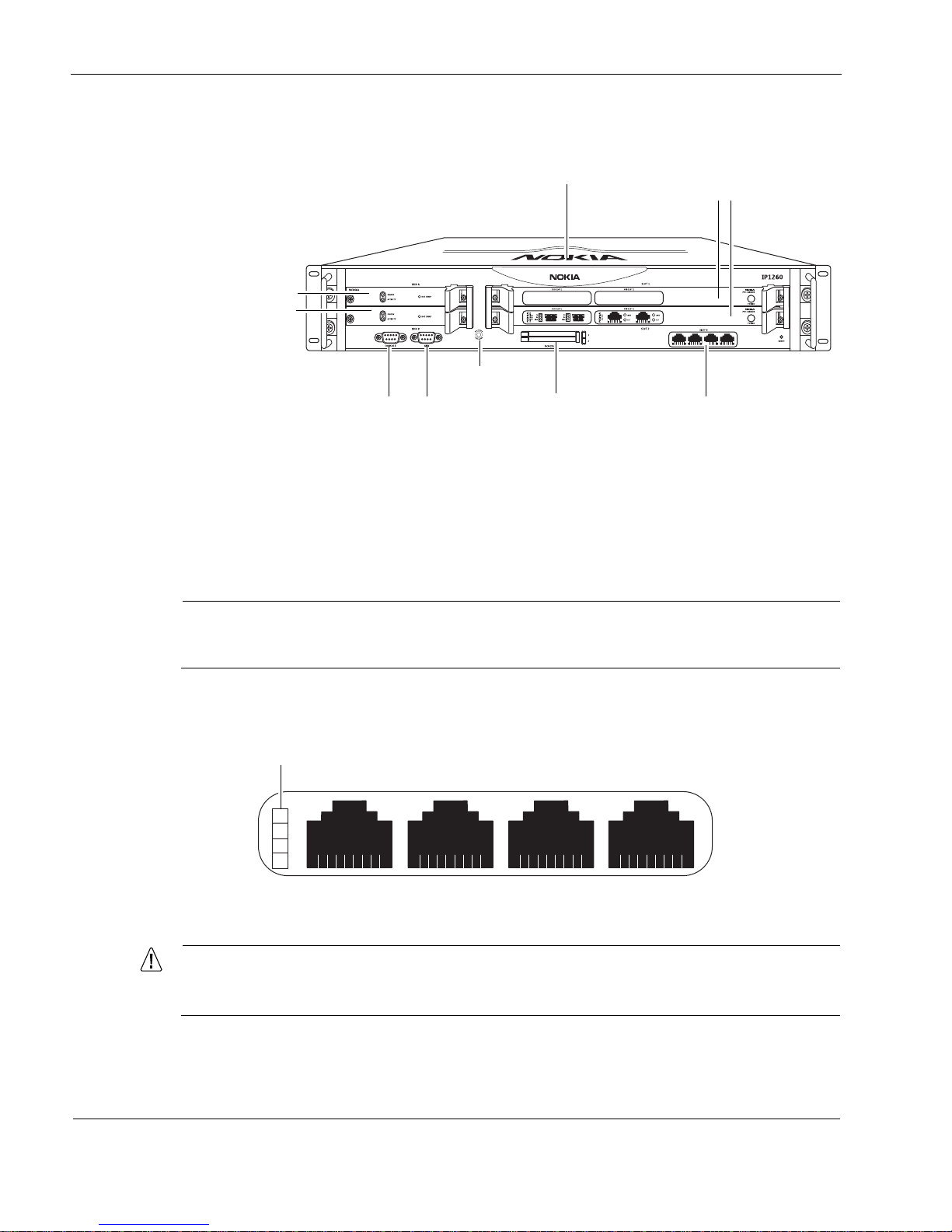
Figure 1 Component Locations Front View
Ethernet Management Ports
The Ethernet management ports are located in slot 3. Figure 2 shows the layout of the Ethernet
management ports and link LEDs. The top link LED represents the left-most port (port 1). The
remaining LEDs represent the remaining ports from top to bottom and left to right.
Note
The Ethernet management ports are intended for management purposes. These ports do
not provide the same performance as Ethernet cards in the PMC slots.
Figure 2 Ethernet Management Ports Details
Caution
Cables that connect to the Ethernet NIC must be IEEE 802.3 compliant to prevent
potential data loss.
00307a.3
Dual 6U PMC carrier or
ADP module
expansion slots 1 and 2
Console port
System status LEDs
PCMCIA slots Ethernet management
ports (slot 3)
Serial (AUX) port
hard-disk drive A
hard-disk drive B
Grounding plug
00120a
RJ-45 connectors
LInk LEDs (green)
Port 1 Port 2 Port 3 Port 4

Nokia IP1200 Series Security Platform Overview
IP1220 and IP1260 Security Platforms Installation Guide 21
PMC Expansion Slots
The IP1200 Series appliance uses two 6U dual PMC carriers in slot 1 and slot 2 to provide up to
four expansion subslots for the NICs listed in Table 4.
Alternatively, you can install a single ADP module in slots 1 and 2. For information about ADP
modules, see Chapter 6, “About IP1200 Appliance ADP Services Modules.”
Note
Nokia products only support NICs and ADP modules purchased from Nokia or Nokiaapproved resellers. The Nokia Global Support Services group can only provide support for
Nokia products that use Nokia-approved accessories. For sales or reseller information,
contact a Nokia service provider listed in the “Nokia Contact Information” on page 3.
Console Port
Use the built-in console port, shown in Figure 1, to supply information that makes the appliance
available on the network. Figure 3 provides pin assignment information for console connections.
If you need to access the devices locally, you must use the console port.
Table 4 PMC Expansion Slots
Interface For details, see...
Four-port Ethernet
(10 or 100 Mbps)
“Four-Port 10/100 Ethernet NICs” on page 58
Four-port Ethernet
(10 or 100 Mbps)
“Four-Port 10/100 Ethernet NICs” on page 58
Two-port fiber-optic Gigabit
Ethernet
“Two-Port Fiber-Optic Gigabit Ethernet NICs” on page 64
Two-port and four-port
copper Gigabit Ethernet
(10/100/1000 Mbps)
“Two-Port and Four-Port Copper Gigabit Ethernet NICs” on page 60

1 Overview
22 IP1220 and IP1260 Security Platforms Installation Guide
Figure 3 Pin Assignments for Console and AUX Connections
Table 5 shows how to match pins at the console or serial connector with output pins on DB9 or
DB25 cables you are using with terminal devices or other appropriate equipment.
Table 5 Pin Assignments for DB9 and DB25 Interface Cables
Console or serial
pin and assignment
DB9 cable output pin and
assignment
DB25 cable output pin and
assignment
Shield (FG) Shield (FG) 1 (FG)
2 (RXD) 3 (TXD) 2 (TXD)
3 (TXD) 2 (RXD) 3 (RXD)
4 (DTR) 6 (DSR) 6 (DSR)
5 (SG) 5 (SG) 7 (SG)
6 (DSR) 4 (DTR) 20 (DTR)
7 (RTS) 8 (CTS) 5 (CTS)
8 (CTS) 7 (RTS) 4 (RTS)
00460
69
5
1
Pin# Assignment
Input or
output
1DCD
(AUX port
only; not used
by the console
port)
Input
2RXD Input
3 TXD Output
4 DTR Output
5GND
6DSR Input
7 RTS Output
8CTS Input
9 not used
Nokia IP1200 Series Security Platform Overview
IP1220 and IP1260 Security Platforms Installation Guide 23
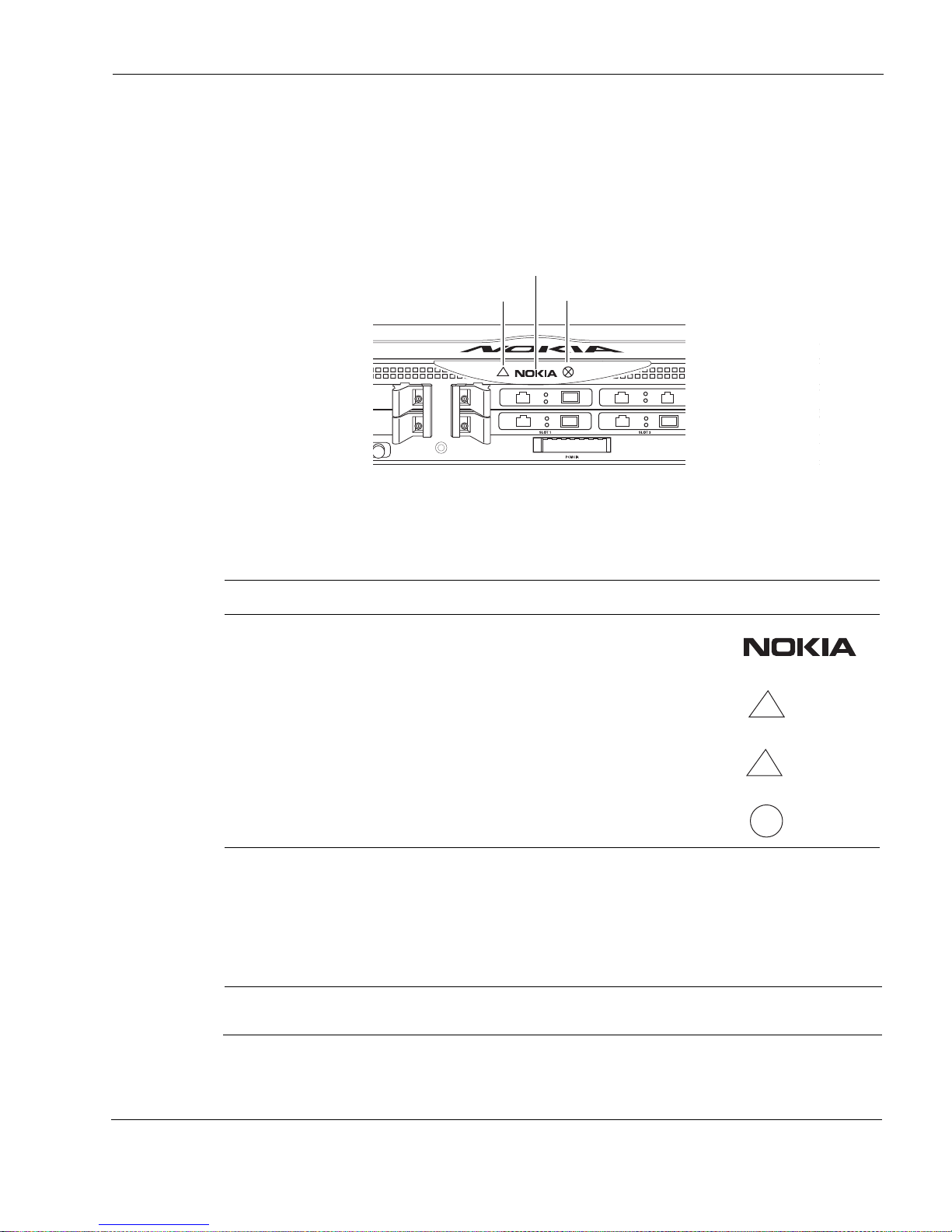
System Status LEDs
You can visually monitor the status of the Nokia IP1200 Series appliance by checking the system
status LEDs. The system status LEDs are located on the center of the front panel, as shown in
Figure 4.
Figure 4 Nokia IP1200 Series Appliance System Status LEDs
The location and meaning of the status LEDs for the installed network interface cards (NICs) is
described in Chapter 5, “About IP1200 Series Appliance Network Interface Cards.”
The location and meaning of the status LEDs for the installed Accelerated Data Path (ADP)
services modules described in Chapter 6, “About IP1200 Appliance ADP Services Modules.”
Note
The symbols in Table 3 are visibly only if there is an alarm condition, as specified.
Table 6 shows the system status LEDs and describes their meaning.
Table 6 System Status LEDs
Status Indicator Meaning Symbol
Solid blue Power on
Solid yellow Appliance is experiencing an internal voltage problem.
Blinking yellow Appliance is experiencing a temperature problem.
Solid red One or more fans are not operating properly.
00307d
E
S
D
C
O
M
M
O
N
P
O
I
N
T
G
R
O
U
N
D
Power/Status
Fault
Warning
!
!
1 Overview
24 IP1220 and IP1260 Security Platforms Installation Guide
Hard-Disk Drives
The Nokia IP1200 Series appliance supports up to two hard-disk drives. The hard-disk drives
support hot swapping, and an optional disk-mirroring feature, described in the following section.
Disk Mirroring
The Nokia disk-mirroring feature provides fault tolerance by allowing the IP1200 Series
appliance to continue working in the event of a disk failure. You can create mirror sets that
consist of a source hard-disk drive (which holds the active copy of the operating system) and
mirror hard-disk drive. The mirror hard-disk drive contains a copy of all of the files on the
source hard-disk drive, and if the source hard-disk drive fails, the mirror hard-disk drive
immediately takes over. The IP1200 Series appliance continues to operate normally, and the
switchover to the secondary mirror drive should be transparent to your data connections.
You can use Nokia Network Voyager, the command-line interface (CLI), or Lynx to create and
delete mirror sets.
Note
The IP1200 series flash-based appliances do not support disk mirroring.
For more information about disk mirroring, including configuration details, see the Nokia
Network Voyager Reference Guide and the Nokia IPSO Getting Started Guide and Release Notes
for the version of Nokia IPSO you are running.
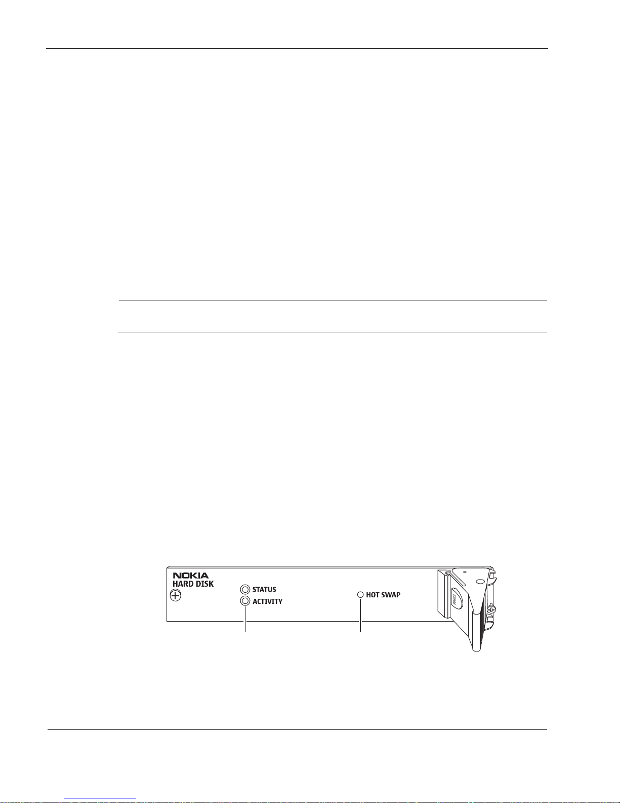
Hard-Disk Drive Hot Swap Feature
If you configure disk mirroring, you can use the hot swap button, shown in Figure 5, to remove
or replace a hard-disk drive without shutting the appliance down. For information about how to
remove and replace a hard-disk drive, see “Replacing a Hard-Disk Drive” on page 82.
Hard-Disk Drive LEDs
The hard-disk drive LEDs are located on the front panel of each hard-disk drive, as shown in
Figure 5. The LEDs provide the status of the hard-disk drives as described in Table 7.
Figure 5 Hard-Disk Drive Front Pane
l
00319
Hard-disk drive LEDs Hot swap button

Nokia IP1200 Series Security Platform Overview
IP1220 and IP1260 Security Platforms Installation Guide 25
Caution
To avoid damage to the ejector and locking lever, loosen the two retaining screws
before you remove the hard-disk drive. Once screw is located behind the ejector and
locking lever, and the other screw is on the opposite side.
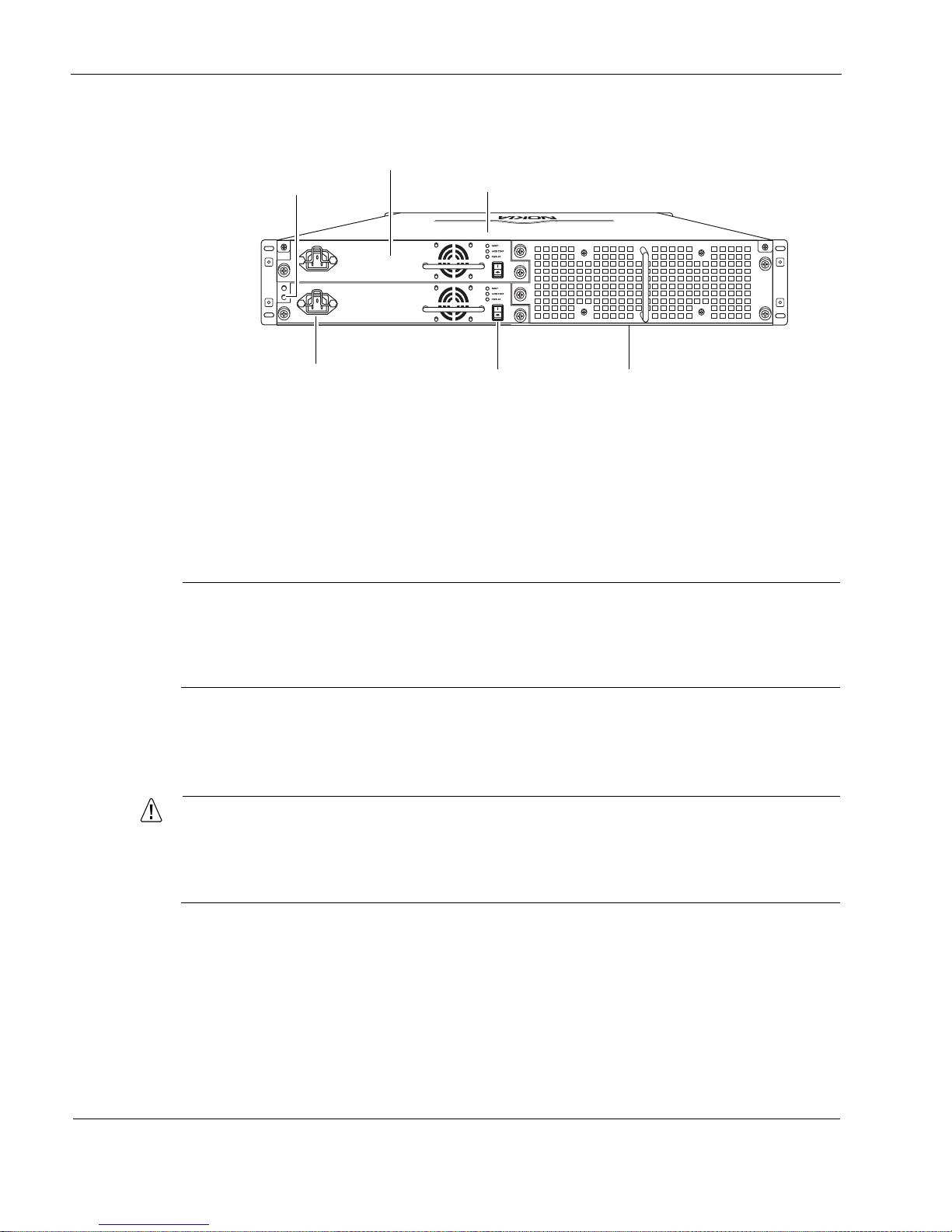
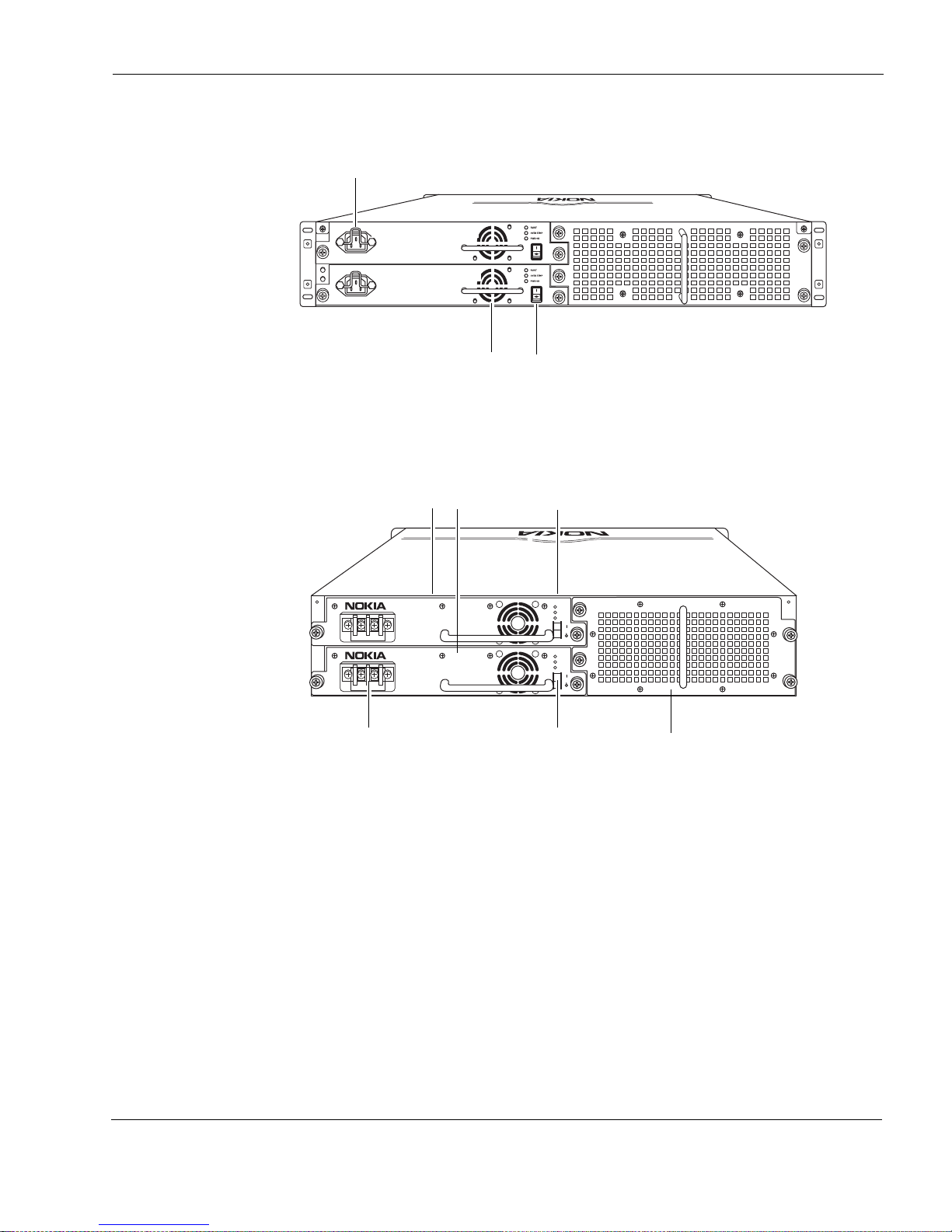
Power Supplies and Fan Unit
The power supplies and fan unit are located at the rear of the IP1200 Series appliance, as shown
in Figure 6.
Table 7 Hard-Disk Drive LEDs
LED LED State Meaning
Activity Off No current disk activity.
Blinking green Current disk activity.
Status Solid red hard-disk drive is turned on but is malfunctioning.
Solid green hard-disk drive is turned on and is functioning.
Off One of the following:
• hard-disk drive failed its test and was powered off.
• hard-disk drive is ready to be removed using the hot swap
feature.
Blinking green One of the following:
• System is booting.
• hard-disk drive is starting up.
• System is testing the hard-disk drive.
Note
Do not remove the hard-disk drive if the Status LED is
blinking green.
1 Overview
26 IP1220 and IP1260 Security Platforms Installation Guide
Figure 6 Power Supply and Fan Unit Locations
Power Supplies
The Nokia IP1200 Series appliance supports up to two power supplies for power sharing and
redundancy. The IP1260 comes with two power supplies as the standard package. The IP1220
comes with power supply; a second one is optional. The power supplies are hot swappable and
perform load sharing while two active power supplies are installed, increasing the life of the
power supplies.
Note
On an appliance with two active power supplies installed, both power supplies should be
turned on for load sharing and redundancy. If both power supplies are not turned on, the
Fault LED illuminates. For more information about the power supply status LEDs, see
“Power Supply Status LEDs” on page 28.
The power supplies are autosensing and can accept input voltages between 85 VAC and 264
VAC. The power supply output is regulated to a tolerance of ± 5 percent of the specified output
voltage.
Caution
The Nokia IP1200 Series appliance power supply might be hot to the touch when the
power supply unit is plugged in to an AC power source and the power supply is not
turned on. This is because the internal cooling fan for each power supply runs only
when the unit is turned on.
00308a
Power cord receptacle Power switch
Power supplies
Fan unit
Status LEDs
Grounding studs
Nokia IP1200 Series Security Platform Overview
IP1220 and IP1260 Security Platforms Installation Guide 27
Figure 7 AC Power Supply, Cooling Fan, and Power Switch
Figure 8 Power Supply and Fan Unit Locations (DC version)
For information about how to install or remove and replace a failed power supply, see “Installing
or Replacing a Power Supply” on page 108.
DC Power Supplies
For IP1200 Series appliances that use DC power supplies, the following specifications apply for
Nokia approved components:
Input voltage:
-48 volts DC nominal
-40 to - 60 volts DC auto-ranging (capable)
Input current:
10 amps maximum at -40 volts DC
00308a
Power supply switchCooling fan
AC power receptacle
Power supply A
Power supply B
00624
700W AC
FAULT
OVER
TEMP
PWR OK
+
—
700W AC
FAULT
OVER
TEMP
PWR OK
+
—
Power connections
Power switches
Power supplies
Fan unit
Status LEDs

1 Overview
28 IP1220 and IP1260 Security Platforms Installation Guide
Power Supply Status LEDs
The power supply status LEDs provide the status of the power supplies as described in Table 8.
Fan Unit
The IP1200 Series appliance fan unit is a single unit made up of eight individual fans to provide
the air flow required to maintain a proper operating temperature. The fan unit can provide proper
airflow for a short time even if an individual fan fails.
Caution
If an individual fan fails, replace the fan unit as soon as possible. For information about
how to replace a failed fan unit, see “Installing a Fan Unit” on page 107.
The system status LEDs on the front panel of the appliance show the status of the fan unit. For
more information about the system status LEDs, see “System Status LEDs” on page 23.
Site Requirements
Before you install an IP1200 Series appliance, ensure that your computer room or wiring closet
conforms to the environmental specifications listed in Appendix A, “Technical Specifications.”
Safety Warnings and Cautions
Warning
Hazardous radiation exposure can occur if you use controls, make performance
adjustments, or follow procedures that are not described in this document.
Table 8 Power Supply Status LEDs
LED LED status Meaning
Fault Red Power supply has a voltage problem and power was turned
off.
or
One power supply in a redundant system is not turned on.
Over Temp Yellow Power supply has an internal temperature problem. All
power to the unit is turned off. After the internal temperature
returns to normal, power will be turned back on.
PWR OK Green Power is on and the power supply is functioning properly.

Safety Warnings and Cautions
IP1220 and IP1260 Security Platforms Installation Guide 29
Warning
To reduce the risk of fire, electric shock, and injury when you use telephone equipment,
follow basic safety precautions. Do not use the product near water.
Warning
On IP1200 Series intended for shipment outside of the United States, the cord set might be
optional. If a cord set is not provided, use a power cord rated at 10A, 250V, maximum 15
feet long, made of HAR cordage and IEC fittings approved by the country of end use.
Warning
Replacement of fuses replaceable only by service personnel.
Caution
Replace the battery only with the same or equivalent type battery recommended by the
manufacturer. Dispose of used batteries according to the manufacturer's instructions.
Caution
Do not block any of the ventilation holes on the appliance. The components might
overheat and become damaged.
Note
A readily accessible disconnect device shall be incorporated in the building installation
wiring.
Note
Installation instructions indicate listed circuit breaker or branch rated fuse, rating, number of
poles, and special characteristics.

1 Overview
30 IP1220 and IP1260 Security Platforms Installation Guide
Software Requirements
Table 9 and Table 10 describe operating system and applications requirements for the Nokia
IP1200 Series appliances.
For information about updates to the software requirements or additional applications that have
become available since this guide was published, contact your Nokia service provider, as listed
in “Nokia Contact Information” on page 3.
Product Disposal
At the end of its useful life, your appliance and all peripherals included with it, including power
cords and cables, must be disposed of in accordance with all applicable national, state, and local
laws and regulations. These devices contain materials and components that must be disposed of
properly. Therefore, to help prevent damage to the environment, Nokia encourages you to
dispose of these devices in an environmentally-friendly manner.
The following resources are available to you to help with equipment-disposal decisions:
Many Nokia products are labeled with information about the materials used in their
manufacture that can help those who will process equipment after you have disposed of it.
The Nokia web site (http://www.nokia.com) provides information about our environmental
programs and practices, which includes details about materials used in manufacturing and
end-of-life practices. You can also find your product’s Eco Declaration, which provides
basic information on the environmental attributes of the product covering material use,
packaging, disassembly, and recycling.
Table 9 Nokia IP1200 Series Disk-Based Platform Software Requirements
Platform
Nokia IPSO
Versi on Software
Nokia IP1260 v3.7 or later Check Point VPN-1 versions compatible with the version of Nokia
IPSO you are using
Nokia IP1220 v3.7.1 or later Check Point VPN-1 versions compatible with the version of Nokia
IPSO you are using
Table 10 Nokia IP1200 Series Flash-Based Platform Software Requirements
Platform
Nokia IPSO
Version Software
Nokia IP1220 v3.9 or later Check Point VPN-1 versions compatible with the version of Nokia
IPSO you are using
Nokia IP1260 v3.9 or later Check Point VPN-1 versions compatible with the version of Nokia
IPSO you are using
 Loading...