

Nokia IP1200 Installation Manual
Nokia IP1200 Series
Security Platform
Installation Guide
Part No. N450897003 Rev B
Published May 2004

COPYRIGHT
©2004 Nokia. All rights reserved.
Rights reserved under the copyright laws of the United States.
RESTRICTED RIGHTS LEGEND
Use, duplication, or disclosure by the United States Government is subject to restrictions as set
forth in subparagraph (c)(1)(ii) of the Rights in Technical Data and Computer Software clause at
DFARS 252.227-7013.
Notwithstanding any other license agreement that may pertain to, or accompany the delivery of,
this computer software, the rights of the United States Government regarding its use,
reproduction, and disclosure are as set forth in the Commercial Computer Software-Restricted
Rights clause at FAR 52.227-19.
IMPORTANT NOTE TO USERS
This software and hardware is provided by Nokia Inc. as is and any express or implied
warranties, including, but not limited to, implied warranties of merchantability and fitness for a
particular purpose are disclaimed. In no event shall Nokia, or its affiliates, subsidiaries or
suppliers be liable for any direct, indirect, incidental, special, exemplary, or consequential
damages (including, but not limited to, procurement of substitute goods or services; loss of use,
data, or profits; or business interruption) however caused and on any theory of liabi lity, whether in
contract, strict liability, or tort (including negligence or otherwise) arising in any way out of the use
of this software, even if advised of the possibility of such damage.
Nokia reserves the right to make changes without further notice to any products herein.
TRADEMARKS
Nokia is a registered trademark of Nokia Corporation. Other products mentioned in this
document are trademarks or registered trademarks of their respective holders.
040113
2 Nokia IP1200 Series Security Platform Installation Guide

Nokia Contact Information
Corporate Headquarters
Web Site http://www.nokia.com
Telephone 1-888-477-4566 or
1-650-625-2000
Fax 1-650-691-2170
Mail
Address
Regional Contact Information
Americas Nokia Inc.
Europe,
Middle East,
and Africa
Asia-Pacific 438B Alexandra Road
Nokia Customer Support
Web Site: https://support.nokia.com/
Email: tac.support@nokia.com
Nokia Inc.
313 Fairchild Drive
Mountain View, California
94043-2215 USA
313 Fairchild Drive
Mountain View, CA 94043-2215
USA
Nokia House, Summit Avenue
Southwood, Farnborough
Hampshire GU14 ONG UK
#07-00 Alexandra Technopark
Singapore 119968
Tel: 1-877-997-9199
Outside USA and Canada: +1 512-437-7089
email: ipsecurity.na@nokia.com
Tel: UK: +44 161 601 8908
Tel: France: +33 170 708 166
email: ipsecurity.emea@nokia.com
Tel: +65 6588 3364
email: ipsecurity.apac@nokia.com
Americas Europe
Voice: 1-888-361-5030 or
Fax: 1-613-271-8782 Fax: +44 (0) 125-286-5666
Asia-Pacific
Voice: +65-67232999
Fax: +65-67232897
Nokia IP1200 Series Security Platform Installation Guide 3
Voice: +44 (0) 125-286-8900
1-613-271-6721
031014

4 Nokia IP1200 Series Security Platform Installation Guide

Contents
About this Guide . . . . . . . . . . . . . . . . . . . . . . . . . . . . . . . . . . . . . .15
In This Guide . . . . . . . . . . . . . . . . . . . . . . . . . . . . . . . . . . . . . . . . . 15
Conventions This Guide Uses . . . . . . . . . . . . . . . . . . . . . . . . . . . . 16
Notices . . . . . . . . . . . . . . . . . . . . . . . . . . . . . . . . . . . . . . . . . . . . 16
Text Conventions . . . . . . . . . . . . . . . . . . . . . . . . . . . . . . . . . . . . 17
Related Documentation . . . . . . . . . . . . . . . . . . . . . . . . . . . . . . . . . 18
1 Overview . . . . . . . . . . . . . . . . . . . . . . . . . . . . . . . . . . . . . . . . . . . 19
About the Nokia IP1200 Series Security Platform . . . . . . . . . . . . . 19
Managing the Nokia IP1200 Series Security Platform . . . . . . . . . . 21
Nokia IP1200 Series Security Platform Overview . . . . . . . . . . . . . 23
Ethernet Management Ports. . . . . . . . . . . . . . . . . . . . . . . . . . . . 24
PMC Expans io n S lo ts . . . . . . . . . . . . . . . . . . . . . . . . . . . . . . . . . 24
Console Port . . . . . . . . . . . . . . . . . . . . . . . . . . . . . . . . . . . . . . . . 26
Serial (AUX) Port. . . . . . . . . . . . . . . . . . . . . . . . . . . . . . . . . . . . . 27
System Sta tu s LE Ds . . . . . . . . . . . . . . . . . . . . . . . . . . . . . . . . . . 28
Hard Disk Drives . . . . . . . . . . . . . . . . . . . . . . . . . . . . . . . . . . . . . 29
Disk Mirroring . . . . . . . . . . . . . . . . . . . . . . . . . . . . . . . . . . . . . . 29
Hard-Disk Drive Hot Swap Feature . . . . . . . . . . . . . . . . . . . . . 30
Hard-Disk Drive LEDs . . . . . . . . . . . . . . . . . . . . . . . . . . . . . . . 30
Power Supplies and Fan Unit . . . . . . . . . . . . . . . . . . . . . . . . . . . 32
Power Supp lie s . . . . . . . . . . . . . . . . . . . . . . . . . . . . . . . . . . . . 33
Fan Unit . . . . . . . . . . . . . . . . . . . . . . . . . . . . . . . . . . . . . . . . . . 35
Site Requirements, Warnings, and Cautions . . . . . . . . . . . . . . . . . 36
Software Requirements . . . . . . . . . . . . . . . . . . . . . . . . . . . . . . . . . 37
Nokia IP1200 Series Security Platform Installation Guide 5

2 Performing the Initial Configuration . . . . . . . . . . . . . . . . . . . . . 39
Using a Console Connection . . . . . . . . . . . . . . . . . . . . . . . . . . . . . 40
Connecting Power and Turning the Power On. . . . . . . . . . . . . . . . 42
Performing the Initial Configuration . . . . . . . . . . . . . . . . . . . . . . . . 44
Connecting Network Interfaces . . . . . . . . . . . . . . . . . . . . . . . . . . . 46
Using Nokia Network Voyager to Manage Your Security Platform 47
Accessing Nokia Network Voyager Reference Info rmation. . . . . 48
Nokia Network Voyager Reference Guide . . . . . . . . . . . . . . . . 49
Nokia Network Voyager Inline Help . . . . . . . . . . . . . . . . . . . . . 49
Using Nokia Network Voyager to Monitor a Nokia IP1200 Series
Security Platform . . . . . . . . . . . . . . . . . . . . . . . . . . . . . . . . . . . 50
Using the Command-Line Interface to Manage Your Security
Platform . . . . . . . . . . . . . . . . . . . . . . . . . . . . . . . . . . . . . . . . . . . . . 50
Using Nokia Horizon Manager. . . . . . . . . . . . . . . . . . . . . . . . . . . . 51
3 Installing the Nokia IP1200 Seri es Security Platform . . . . . . . 53
Rack Mounting the Security Platform. . . . . . . . . . . . . . . . . . . . . . . 53
Before You Begin. . . . . . . . . . . . . . . . . . . . . . . . . . . . . . . . . . . . . . 54
4 Installing and Replacing Ne twork Interface Cards . . . . . . . . . 61
Removing, Installing, and Replacing NICs. . . . . . . . . . . . . . . . . . . 62
Before You Begin . . . . . . . . . . . . . . . . . . . . . . . . . . . . . . . . . . . . 63
Configuring and Activating Interfaces . . . . . . . . . . . . . . . . . . . . . . 70
Monitoring Ne tw o r k In terface Card s. . . . . . . . . . . . . . . . . . . . . . . . 71
5 Connecting PMC Network Interface Cards . . . . . . . . . . . . . . . . 73
Four-Port and Dual-Port 10/100 Ethernet NICs. . . . . . . . . . . . . . . 75
10/100 Ethernet NIC Features . . . . . . . . . . . . . . . . . . . . . . . . . . 75
Ethernet NIC Connectors and Cables. . . . . . . . . . . . . . . . . . . . . 77
Dual-Port Fiber-Optic Gigabit Ethernet NIC. . . . . . . . . . . . . . . . . . 78
Fiber-Optic Gigabit Ethernet NIC Features. . . . . . . . . . . . . . . . . 79
6 Nokia IP1200 Series Security Platform Installation Guide

Fiber-Optic Gigabit Ethernet NIC Connectors and Cables . . . . . 80
Dual-Port Copper Gigabit Ethernet NIC. . . . . . . . . . . . . . . . . . . . . 80
Performance Considerations . . . . . . . . . . . . . . . . . . . . . . . . . . . . . 80
Copper Gigabit Ethernet NIC Features. . . . . . . . . . . . . . . . . . . . 81
Dual-Port Copper Gigabit Ethernet NIC Connectors and Cables 82
Single-Port ISDN S/T NIC . . . . . . . . . . . . . . . . . . . . . . . . . . . . . . . 85
Single-Port ISDN S/T NIC Features . . . . . . . . . . . . . . . . . . . . . . 86
ISDN NIC Connectors and Cables . . . . . . . . . . . . . . . . . . . . . . . 86
Single-Po rt V. 3 5 or X .2 1 N IC . . . . . . . . . . . . . . . . . . . . . . . . . . . . . 87
Single-Po rt V. 3 5 or X .2 1 N IC F ea t u re s . . . . . . . . . . . . . . . . . . . . 88
V.35 and X.21 NIC Connectors and Cables . . . . . . . . . . . . . . . . 89
Single-Port T1 NIC . . . . . . . . . . . . . . . . . . . . . . . . . . . . . . . . . . . . . 91
Connectors and Cables. . . . . . . . . . . . . . . . . . . . . . . . . . . . . . . . 93
Single-Port E1 NIC. . . . . . . . . . . . . . . . . . . . . . . . . . . . . . . . . . . . . 95
Connectors and Cables. . . . . . . . . . . . . . . . . . . . . . . . . . . . . . . . 96
6 Using the Boot Manager . . . . . . . . . . . . . . . . . . . . . . . . . . . . . . . 99
Variables . . . . . . . . . . . . . . . . . . . . . . . . . . . . . . . . . . . . . . . . . . . 100
Viewing the Variables and Other System Parameters . . . . . . . 101
printenv. . . . . . . . . . . . . . . . . . . . . . . . . . . . . . . . . . . . . . . . . . 101
sysinfo . . . . . . . . . . . . . . . . . . . . . . . . . . . . . . . . . . . . . . . . . . 102
ls. . . . . . . . . . . . . . . . . . . . . . . . . . . . . . . . . . . . . . . . . . . . . . . 103
Setting the Variables. . . . . . . . . . . . . . . . . . . . . . . . . . . . . . . . . 103
setenv. . . . . . . . . . . . . . . . . . . . . . . . . . . . . . . . . . . . . . . . . . . 103
unsetenv. . . . . . . . . . . . . . . . . . . . . . . . . . . . . . . . . . . . . . . . . 104
set-defaults. . . . . . . . . . . . . . . . . . . . . . . . . . . . . . . . . . . . . . . 104
setalias . . . . . . . . . . . . . . . . . . . . . . . . . . . . . . . . . . . . . . . . . . 105
unsetalias . . . . . . . . . . . . . . . . . . . . . . . . . . . . . . . . . . . . . . . . 105
Other commands. . . . . . . . . . . . . . . . . . . . . . . . . . . . . . . . . . . . 106
halt . . . . . . . . . . . . . . . . . . . . . . . . . . . . . . . . . . . . . . . . . . . . . 106
Nokia IP1200 Series Security Platform Installation Guide 7

help. . . . . . . . . . . . . . . . . . . . . . . . . . . . . . . . . . . . . . . . . . . . . 106
Booting the System . . . . . . . . . . . . . . . . . . . . . . . . . . . . . . . . . . . 106
Using the Boot Manager to Install Nokia IPSO . . . . . . . . . . . . . . 107
Protecting the Boot Manager with a Password . . . . . . . . . . . . . . 108
Installing the Boot Manager . . . . . . . . . . . . . . . . . . . . . . . . . . . . . 109
Upgrading the Boot Manager. . . . . . . . . . . . . . . . . . . . . . . . . . . . 109
7 Troubleshooting . . . . . . . . . . . . . . . . . . . . . . . . . . . . . . . . . . . . 111
General Troubleshooting Information. . . . . . . . . . . . . . . . . . . . . . 111
8 Installing and Replacing Other Components . . . . . . . . . . . . . 119
Replacing a Hard Disk Drive . . . . . . . . . . . . . . . . . . . . . . . . . . . . 120
Disk Mirroring . . . . . . . . . . . . . . . . . . . . . . . . . . . . . . . . . . . . . . 120
Hard Disk Drive Hot Swap Feature. . . . . . . . . . . . . . . . . . . . . . 121
Before You Begin . . . . . . . . . . . . . . . . . . . . . . . . . . . . . . . . . . . 122
Removing and Replacing a Hard Disk Drive . . . . . . . . . . . . . 122
Replacing or Upgrading Memory . . . . . . . . . . . . . . . . . . . . . . . . . 128
Before You Begin . . . . . . . . . . . . . . . . . . . . . . . . . . . . . . . . . . . 130
Installing a Nokia Encrypti on Accelerator Card . . . . . . . . . . . . . . 134
Before You Begin . . . . . . . . . . . . . . . . . . . . . . . . . . . . . . . . . . . 135
Configuring Software to Use Hardware Acceleration . . . . . . . . 139
Installing a Fan Unit . . . . . . . . . . . . . . . . . . . . . . . . . . . . . . . . . . . 140
Before You Begin . . . . . . . . . . . . . . . . . . . . . . . . . . . . . . . . . . . 140
Installing or Replacing a Power Supply . . . . . . . . . . . . . . . . . . . . 141
Before You Begin . . . . . . . . . . . . . . . . . . . . . . . . . . . . . . . . . . . 143
Monitoring the Nokia IP1200 Series Security Platfor m Power
Supply . . . . . . . . . . . . . . . . . . . . . . . . . . . . . . . . . . . . . . . . . . . . . 144
A Technical Specifications . . . . . . . . . . . . . . . . . . . . . . . . . . . . . 145
Space Requirements . . . . . . . . . . . . . . . . . . . . . . . . . . . . . . . . . . 146
8 Nokia IP1200 Series Security Platform Installation Guide

B Compliance Information . . . . . . . . . . . . . . . . . . . . . . . . . . . . . . 147
Declaration of Conformity. . . . . . . . . . . . . . . . . . . . . . . . . . . . . . . 148
Compliance Statements. . . . . . . . . . . . . . . . . . . . . . . . . . . . . . . . 150
FCC Notice (US) . . . . . . . . . . . . . . . . . . . . . . . . . . . . . . . . . . . . . 151
Equipment Attachment Regulations (Canada). . . . . . . . . . . . . . . 152
Index . . . . . . . . . . . . . . . . . . . . . . . . . . . . . . . . . . . . . . . . . . . . . . 153
Nokia IP1200 Series Security Platform Installation Guide 9

10 Nokia IP1200 Series Security Platform Installation Guide

Figures
Figure 1 Component Locations Front View . . . . . . . . . . . . . . . . . 23
Figure 2 Ethernet Management Ports Details . . . . . . . . . . . . . . . 24
Figure 3 Pin Assignments for Console Connection . . . . . . . . . . . 26
Figure 4 Pin Assignments for Modem Connection . . . . . . . . . . . 27
Figure 5 Nokia IP1200 Series Security Platform System
Status LEDs . . . . . . . . . . . . . . . . . . . . . . . . . . . . . . . . 28
Figure 6 Hard-Disk Drive Front Panel . . . . . . . . . . . . . . . . . . . . . 31
Figure 7 Power Supply and Fan Unit Locations . . . . . . . . . . . . . 33
Figure 8 Power Supply, Cooling Fan, and Power Switch
Locations . . . . . . . . . . . . . . . . . . . . . . . . . . . . . . . . . . 34
Figure 9 Power Switch Location . . . . . . . . . . . . . . . . . . . . . . . . . 42
Figure 10 Nokia Network Voyager Reference Access Points
Example . . . . . . . . . . . . . . . . . . . . . . . . . . . . . . . . . . . 49
Figure 11 Rack-Mounting Screw Locations . . . . . . . . . . . . . . . . . 54
Figure 12 Four-Port 10/100 Ethernet NIC Front Panel Details . . 76
Figure 13 Dual-Port 10/100 Ethernet NIC Front Panel Details . . 76
Figure 14 Output Connector for the Ethernet Cable . . . . . . . . . . 77
Figure 15 Ethernet Crossover-Cable Pin Connections . . . . . . . . 78
Figure 16 Dual-Port Fiber-Optic Gigabit Ethernet NIC Front
Panel Details . . . . . . . . . . . . . . . . . . . . . . . . . . . . . . . 79
Figure 17 Dual-Port Copper Gigabit Ethernet NIC Front Panel
Details . . . . . . . . . . . . . . . . . . . . . . . . . . . . . . . . . . . . 82
Figure 18 Ethernet Cable Connector Output Pin Assignments . . 84
Nokia IP1200 Series Security Platform Installation Guide 11

Figure 19 Ethernet Crossover Cable Pin Connections . . . . . . . . 85
Figure 20 Single-Port ISDN S/T Interface Front Panel Details . . 86
Figure 21 Output Connector for the ISDN Cable . . . . . . . . . . . . 87
Figure 22 Single-Port V.35 or X.21 NIC Front Panel Details . . . 89
Figure 23 Output Connector for the V.35 Cable . . . . . . . . . . . . . 90
Figure 24 Output Connector for the X.21 Cable . . . . . . . . . . . . . 91
Figure 25 Single-Port T1 NIC Front Panel Details . . . . . . . . . . . 93
Figure 26 T1 Network Interface Card Receptacle and Pin
Assignments . . . . . . . . . . . . . . . . . . . . . . . . . . . . . . . . 94
Figure 27 T1 Crossover Cable Pin Connections . . . . . . . . . . . . . 95
Figure 28 Single-Port E1 NIC Front Panel Details . . . . . . . . . . . 96
Figure 29 E1 Network Interface Card Receptacle and Pin
Assignments . . . . . . . . . . . . . . . . . . . . . . . . . . . . . . . . 98
Figure 30 E1 Crossover Cable Connection Diagram . . . . . . . . . 98
Figure 31 Location of Hard Disk Drives . . . . . . . . . . . . . . . . . . 120
Figure 32 DIMM Socket Locations . . . . . . . . . . . . . . . . . . . . . . 129
12 Nokia IP1200 Series Security Platform Installation Guide

Tables
Table 1 Text Conventions . . . . . . . . . . . . . . . . . . . . . . . . . . . . . . 17
Table 2 Nokia IP1200 Series Security Platform Specifics . . . . . . 20
Table 3 PMC Expansion Slots . . . . . . . . . . . . . . . . . . . . . . . . . . . 25
Table 4 System Status LEDs . . . . . . . . . . . . . . . . . . . . . . . . . . . 28
Table 5 Hard-Disk Drive LED s . . . . . . . . . . . . . . . . . . . . . . . . . . 31
Table 6 Power Supply Status LEDs . . . . . . . . . . . . . . . . . . . . . . 34
Table 7 NIC PCI Frequency . . . . . . . . . . . . . . . . . . . . . . . . . . . . 72
Table 8 Boot Manager Variables . . . . . . . . . . . . . . . . . . . . . . . . . 98
Nokia IP1200 Series Security Platform Installation Guide 13

14 Nokia IP1200 Series Security Platform Installation Guide

About this Guide
This manual provides information for the installation and use of the Nokia
IP1200 Series Security Platforms. Installation and maintenance should be
performed by experienced technicians or Nokia-approved service providers
only.
This preface provides the following information:
In This Guide
Conventions This Guide Uses
Related Documentation
In This Guide
This guide is organized into the following chapters and appendixes:
Chapter 1, “Overview” presents a general overview of the Nokia IP1200
Series Security Platf orm.
Chapter 3, “Installing the Nokia IP1200 Series Security Platform”
describes how to rack mount the security platform.
Chapter 2, “Performing the Initial Configuration” describes how to
physically conne ct i t t o a network a nd to a po wer sourc e and how t o ma ke
the security platform available on the network.
Chapter 4, “Installing and Replacing Network Interface Cards” describes
how to install, monitor, and replace network interface cards (NICs).
Nokia IP1200 Series Security Platform Installation Guide 15

About this Guide
Chapter 5, “Connecting PMC Net w or k I nte rf ace Cards” descri bes ho w to
connect to and use each of the supported NICs.
Chapter 6, “Using the Boot Manager” describes how to use the boot
manager, which is part of the IPSO software.
Chapter 7, “Troubleshooting” discusses problems you might encounter
and proposes solutions to these problems.
Chapter 8, “Installing and Replacing Other Components” describes how
to install or replace memory, hard disk drives, and power supplies.
Appendix A, “Technical Specifications ” provi des te chni cal s pecif icat ion s
such as interface characteristics.
Appendix B, “Compliance Information” provides complian ce and
regulatory information.
Convention s This Guide Uses
Notices
The following sections describe the conventions this guide uses, including
notices, text conventions, and command-line conventions.
Warning
Warnings advise the user that either bodily injury might occur because of
a physical hazard, or that damage to a structure, such as a room or
equipment closet, might occur because of equipment damage.
Caution
Cautions indicate potential equipment damage, equipment
malfunction, loss of performance, loss of data, or interruption of
service.
16 Nokia IP1200 Series Security Platform Installation Guide

Note
Notes provide information of special interest or recommendations.
Text Conventions
Table 1 describes the text conventions this guide uses.
Table 1 Text Conventions
Convention Description
Conventi ons This Guide Uses
monospace font
Indicates command syntax, or represents computer or screen
output, for example:
Log error 12453
bold monospace font
Indicates text you enter or type, for example:
# configure nat
Key names Keys that you press simultaneously are linked by a plus sign (+):
Press Ctrl + Alt + Del.
Menu commands Menu commands are separated by a greater than sign (>):
Choose File > Open.
The words enter and type Enter indicates that you type something and then press the
Return or Enter key.
Do not press the Return or Enter key when an instruction says
type.
Italics
• Emphasizes a point or denotes new terms at the place where
they are defined in the text.
• Indicates an external book title reference.
• Indicates a variable in a command:
delete interface
if_name
Nokia IP1200 Series Security Platform Installation Guide 17

About this Guide
Related Documentation
You can find this guide in PDF on the Nokia support Web site (https://
support.nokia.com/) and on the Nokia IPSO Operating System CD-ROM
issued with your Nokia IP1200 Series Security Platform.
In addition to this guide, documentation for this product includes the
following:
Getting Started Guide and Release Notes for the version of Nokia IPSO
you are using
Nokia Network Voyager Reference Guide
Nokia Network Voyager inline help
Nokia IP Security Platform Quick Setup Guide
Clustering Configuration Guide for the version of IPSO you are using
IPSO Boot Manager Reference Guide
You can access the Network Voyager inline help and the Nokia Network
Voyager Reference Guide from the Network Voyager application.
To access inline help for a specific subject, click Help next to the subject.
To access the Nokia Network Voyager Reference Guide for tasks, examples,
and more information, click Doc.
Check Point documentation is available from the Check Point Web site at
www.checkpoint.com.
18 Nokia IP1200 Series Security Platform Installation Guide

1 Overview
This chapter provides an overview of the Nokia IP1200 Series Security
Platform and the requirements for its use. The following topics are covered:
About the Nokia IP1200 Series Security Platform
Managing the Nokia IP1200 Series Security Platform
Nokia IP1200 Series Security Platform Overview
Site Requirements, Warnings, and Cautions
Software Requirements
About the Nokia IP1200 Series Security Platform
The Nokia IP1200 Series Sec uri t y Pla tf orm combi nes the power of the Nokia
IPSO operating system with the Nokia Secure Access System and firewall
applications. The Nokia IP1260 Security Platform is a high-end, multi port
security platform that is ideally suited for the enterprise data center. The
Nokia IP1220 Security Platform is a mid-range security platform that is
ideally suited for a smaller dat a center. Both IP1200 Series Security Plat forms
support an encryption accelerator card to further enhance VPN performance.
Table 2 presents specifics about the Nokia IP1200 Series Security Platforms.
Nokia IP1200 Series Security Platform Installation Guide 19

1 Overview
Table 2 Nokia IP1200 Series Security Platform Specifics
IP Security
Platform IPSO Versio n Software
IP1260 v3.7 or later Check Point NG FP3 (hf2)
Nokia Secure Access System
v1.02 or later
IP1220 v3.8 or later Check Point NG with
Application Intelligence R55
The IP1200 Series is a two-rac k uni t appli ance tha t incor porat es a servi ceabl e
slide-out tray in to the c has sis de sign. The front panel of th e IP1200 Series has
two I/O slots that support hot-swapping operations. A PMC carrier is
provided for the I/O slots. Each PMC carrier supports two PMC network
interface cards (NICs) for a total of four NICs. These network interfaces
provide exceptional data forwarding and monitoring performance when used
with Nokia and partner appl ication s. The front pan el of the IP120 0 Series als o
contains:
two storage device slots
two PCMCIA slots
Initial Memory
Configuration
1GB 2GB
512 MB 1 GB
Upgradeable
RAM
a console port
a serial port
a four-port Ethernet manage ment inter fa ce
The network interfaces in the external PMC slot are designated for
management, monitoring, and high-availability traffic. Partner application
and operating system storage is provided on mirrored hard disks in the two
storage device slots.
The IP1200 Series is designed to meet other mid- to high-end availability
requirements, including port density for connections to redundant internal,
external, DMZ, and management networks. In addition, the IP1200 Series
20 Nokia IP1200 Series Security Platform Installation Guide

Managing the Nokia IP1200 Series Security Platform
provides redundant powe r supplies, N + 1 cooling, and hot swappi ng from the
storage and PMC NIC slots.
As a network device, the IP1200 Series supports a comprehensive suite of IProuting functions and protocols, including:
RIPv1/RIPv2
IGRP
OSPF
BGP4 for unicast traffic
DVMRP for multicast traffic
The integrated router functionality eliminates the need for separate intranet
and access routers in security applications.
Managing the Nokia IP1200 Series Secur ity
Platform
You can manage the Nokia IP1200 Series Security Platform by using the
following interfaces:
Nokia Network Voyager—an SSL-secured, Web-based element
management interfa ce to Nokia I P security platforms. Net work Voyag er is
preinstalled on th e IP1200 Serie s and enabled through the IP SO operating
system. With Network Voyager, you can manage, monitor, and configure
the IP1200 Series from any authorized location within the network by
using a standard Web browser. Use one of the four Ethernet management
ports to access the Network Voyager interface.
For information about how to access Network Voyager and the related
reference materials, see “Using Nokia Network Voyager to Manage Your
Security Platform” on page 47.
The IPSO command-line interface (CLI)—an SSHv2-secured interf ace
that enables you to easily configure Nokia IP security platforms from the
command line. Everything that you can accomplish with Network
Nokia IP1200 Series Security Platform Installation Guide 21

1 Overview
Voyager—manage, monitor, and configure the IP1200 Series—you can
also do with the CLI.
For information about how to access the CLI, see the Nokia CLI
Reference Guide for IPSO v3.6 or later.
Nokia Horizon Manager—a secure GUI-b ased software image
management applicatio n. W ith Horizon Ma nager , you can securely ins tall
and upgrade the Nokia proprietary IPSO operating s yst em, plus hardware
and third-party applications such as Check Point VPN-1/FireWall-1 for
Nokia. Horizon Manager can per for m inst al la ti ons and upgrades on up to
2,500 Nokia IP security platforms, offering administrators the most rapid
and dependable upgrade to Check Point NG.
For information about how to obtain Horizon Manager, contact your
Nokia solution provider o r see the “Nokia Contact Information” on page
3.
22 Nokia IP1200 Series Security Platform Installation Guide
Nokia IP1200 Series Security Platform Overview
Nokia IP1200 Series Security Platform Overview
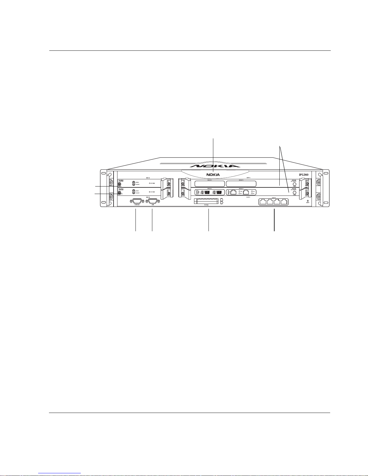
Figure 1 shows the compo nent l ocati ons for the Noki a IP 1200 Ser ies Se curity
Platform.
Figure 1 Component Locations Front View
Hard disk drive A
Hard disk drive B
Console port
System status LEDs
Serial (AUX) port
Dual 6U PMC carrier
expansion slots 1 and 2
00307a.1
PCMCIA slots Ethernet management
ports (slot 3)
Nokia IP1200 Series Security Platform Installation Guide 23
1 Overview
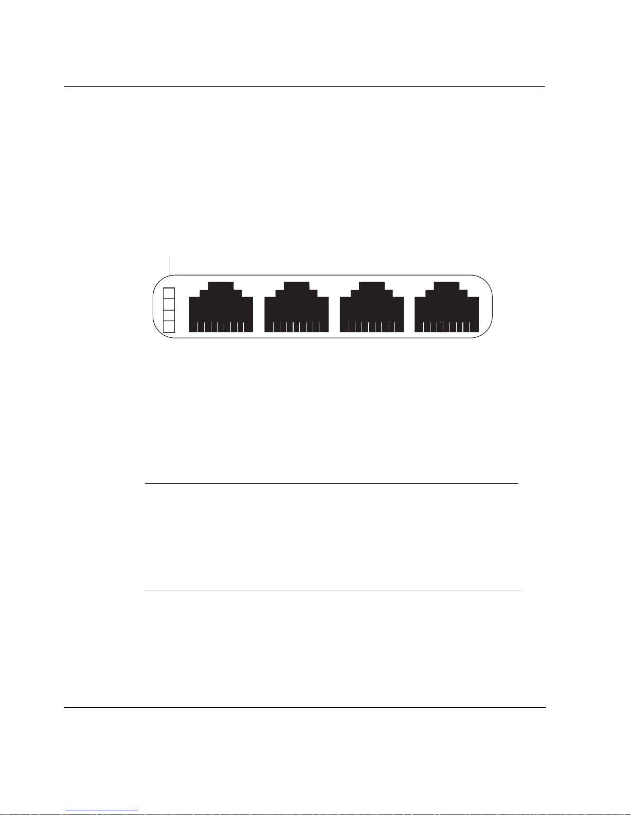
Ethernet Management Ports
The Ethernet management ports are located in slot 3. Figure 2 shows the
layout of the Ethernet management ports and link LEDs. The top link LED
represents the left-most port (port 1). The remaining LEDs represent the
remaining ports from top to bottom and left to right.
Figure 2 Ethernet Management Ports Details
LInk LEDs (green)
Port 1 Port 2 Port 3 Port 4
RJ-45 connectors
00120a
PMC Expansion Slots
The IP1200 Series uses two 6U dual PMC carriers in slot 1 and slot 2 to
provide up to four expansion subslots for the NICs listed in Table 3.
Note
The Nokia IP security platforms are LAN devices that can also use Nokia
NICs for wide area or out-of-band network connections. In the latter case
this must be done with local country approval for Nokia T1, E1, ISDN, or
other NICs. Refer to your reseller or distributor to determine if these NICs
are approved for the desired country . S pecific NICs might not be available
for use in a particular country.
24 Nokia IP1200 Series Security Platform Installation Guide

Nokia IP1200 Series Security Platform Overview
Table 3 PMC Expansion Slots
NIC Type
Interface LAN WAN For details, see...
Four-port Ethernet
(10 or 100 Mbps)
Dual-port Ethernet
(10 or 100 Mbps)
Dual-port fiber-optic
Gigabit Ethernet
Dual-port copper Gigabit
Ethernet (10/100/1000
Mbps)
Single-port ISDN S/T X “Single-Port ISDN S/T
Single-port V.35 or X.21 X “Single -Port V .35 or X.21
Single-port E1 X “Single -Port E1 NIC” on
X “Four-Port and Dual-Port
10/100 Ethernet NICs”
on page 75
X “Four-Port and Dual-Port
10/100 Ethernet NICs”
on page 75
X “Dual-Port Fiber-Optic
Gigabit Ethernet NIC” on
page 78
X “Dual-Port Copper
Gigabit Ethernet NIC” on
page 80
NIC” on page 85
NIC” on page 87
page 95
Single-port T1 X “Single-Port T1 NIC” on
Note
Nokia products only support NICs purchased from Nokia or Nokiaapproved resellers. The Nokia Global Support Services group can only
provide support for Nokia products that use Nokia-approved accessories.
Nokia IP1200 Series Security Platform Installation Guide 25
page 91
1 Overview
1
For sales or reseller information, contact a Nokia service provider listed in
the “Nokia Contact Information” on page 3.
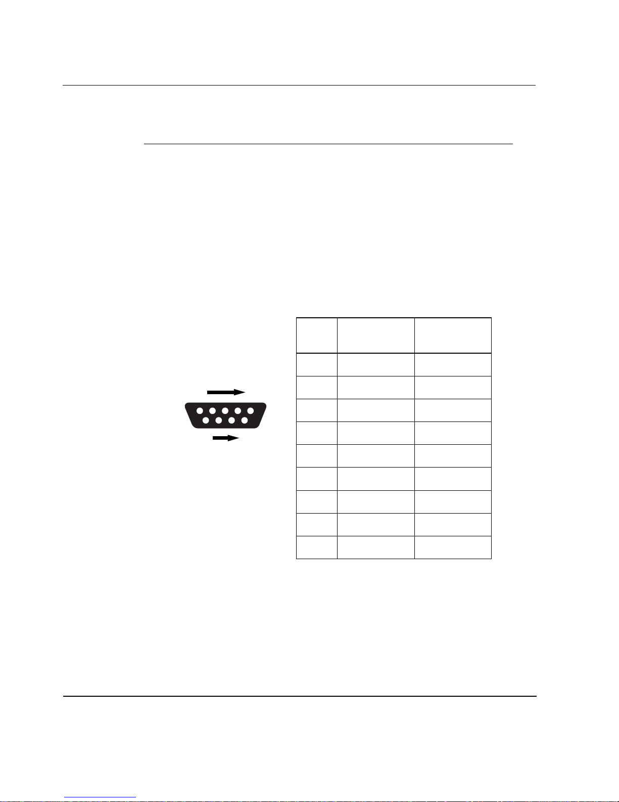
Console Port
Use the built-in console port, shown in Figure 1, to supply information that
makes the appliance available on the network. Figure 3 provides pin
assignment information for console connections. If you need to access the
devices locally, you must use the console port.
Figure 3 Pin Assignments for Console Connection
Pin Assignment Input/Output
1 DCD Input
1
69
5
70000
2RXD Input
3TXD Output
4DTR Output
5GND
6DSR Input
7RTS Output
8CTS Input
9
DTR Output
26 Nokia IP1200 Series Security Platform Installation Guide
Serial (AUX) Port
1
Use the built-in serial (AUX) port, shown in Figure 1, to establish a modem
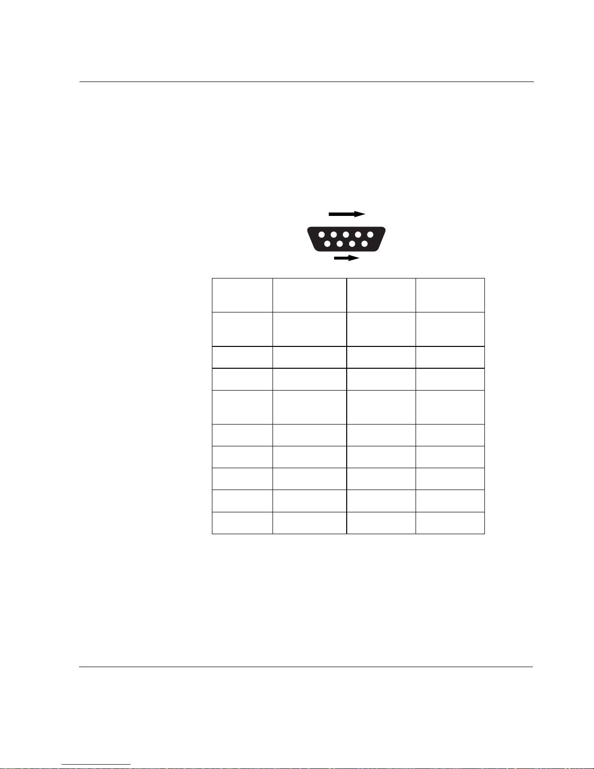
connection for managing the appliance remotely or out-of-Band. Figure 4
provides pin assignment information for modem connections.
Figure 4 Pin Assignments for Modem Connection
Nokia IP1200 Series Security Platform Overview
1
69
Pin Input/Output
1 (DCD) In put 8 (DCD) 7 (RTS)
2 (RXD) Input 2 (TXD) 3 (TXD)
3 (TXD) Output 3 (RXD) 2 (RXD
4 (DTR) Output 20 (DTR) 6 (DSR)
5 (GND) 7 (GND) 5 (GND)
6 (DSR) Input 6 (DSR) 4 (DTR)
7 (RTS) Output 4 (RTS) 1 (DCD)
5
70000
To DB25
Cable Out
To DB9
Cable Out
8 (CTS)
9 (RI)
Nokia IP1200 Series Security Platform Installation Guide 27
8 (CTS) Input 5 (CTS) 1 (DCD)
9 (RI) Output 22 (RI) 4 (DTR)
1 Overview
System Status LEDs
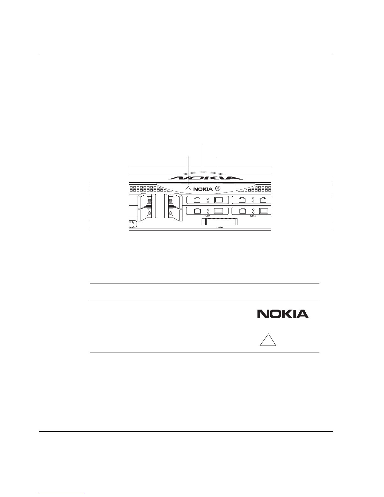
You can visually monitor the status of the Nokia IP1200 Series Security
Platform by checking the system status LEDs. The system status LEDs are
located on the center of the front panel, as shown in Figure 5.
Figure 5 Nokia IP1200 Series Security Platform System Status LEDs
Power/Status
Warning
Fault
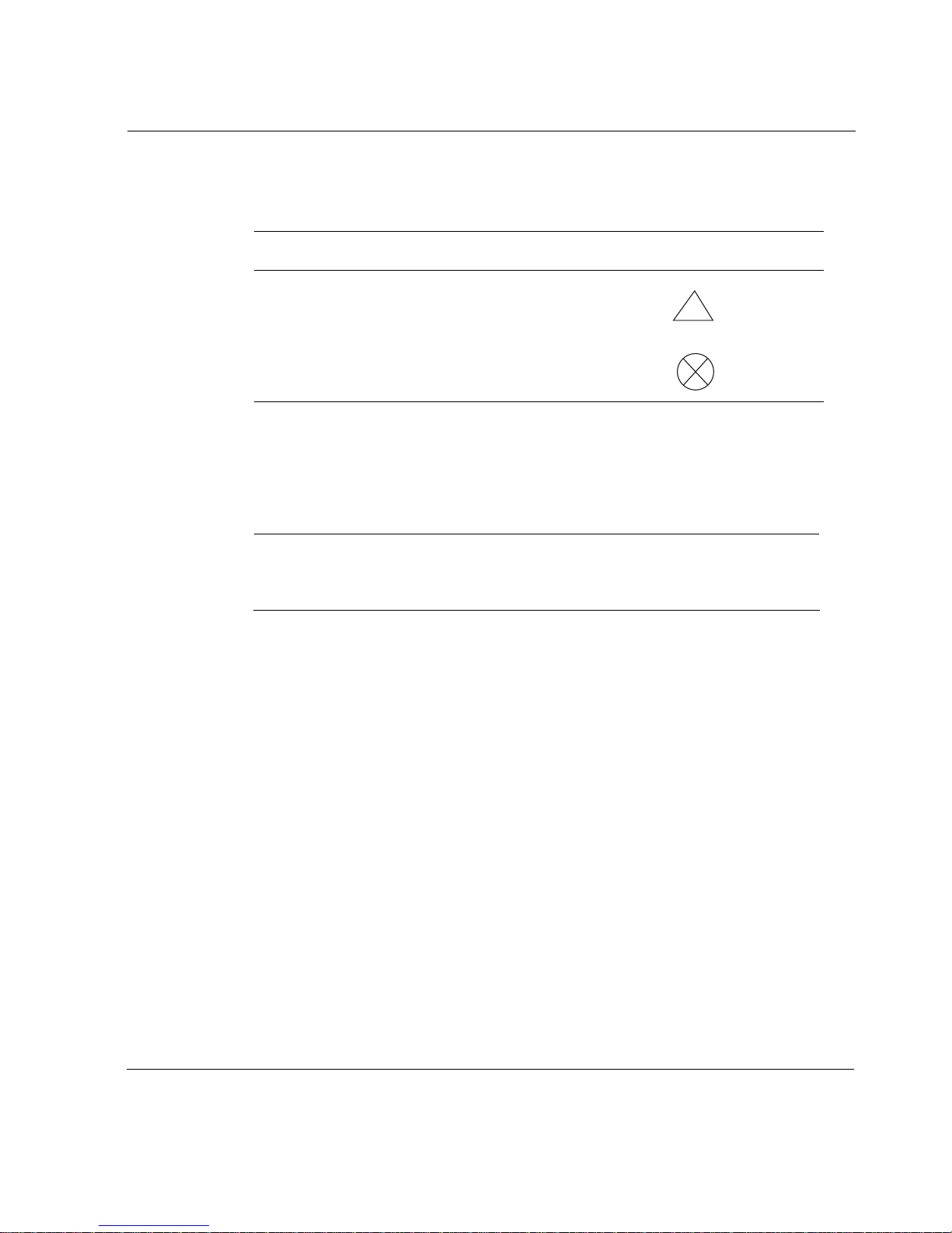
Table 4 shows the system status LEDs and describes their meaning.
Table 4 System Status LEDs
Status Indicator Meaning Symbol
Solid blue Power on
Solid yellow Appliance is experiencing an
internal voltage problem.
!
28 Nokia IP1200 Series Security Platform Installation Guide
Nokia IP1200 Series Security Platform Overview
Table 4 shows the system status LEDs and describes their meaning.
Table 4 System Status LEDs (continued)
Status Indicator Meaning Symbol
Blinking yellow Appliance is experiencing a
temperature problem.
Solid red One or more fans are not
operating properly.
!
The location and meaning of the status LEDs for the installed ne twork
interface cards (NICs) is described in Chapter 5, “Connecting PMC Network
Interface Cards.”
Note
The symbols in Table 3 are visibly only if there is an alarm condition, as
specified.
Hard Disk Drives
The Nokia IP1200 Series Security Platform supports up to two hard disk
drives. The IP1260 comes with two hard disk drives as the standard package.
The IP1220 comes with one hard disk drive; a second one is optional. The
hard disk drive s suppo rt hot s wapping, an d an op tional d isk-mirrori ng feat ure,
described in the following section.
Disk Mirroring
The Nokia disk-mirroring feature provides fault tolerance by allowing the
IP1200 Series to continue working in the event of a disk failure. You can
create mirror sets that consist of a source hard disk drive (which holds the
active copy of the operating system) and mirror hard disk drive. The mirror
Nokia IP1200 Series Security Platform Installation Guide 29

1 Overview
hard disk drive cont ains a cop y of all of the file s on the sour ce hard di sk drive,
and if the source hard disk drive fails, the mirror hard disk drive immediately
takes over. The IP1200 Series continues to operate normally, and the
switchover to the secondary mirror drive should be transparent to your data
connections.
You can use Nokia Network Voyager, the command-line interface (CLI), or
Lynx to create and delete mirror sets.
Note
If your IP1200 Series contains two hard disk drives when you receive it,
the disk-mirroring feature is already enabled.
For more information about disk mirroring, including configuration details,
see the Nokia Network Voyager Reference Guide and the IPSO Release Notes
and Getting Started Guide for the version of IPSO you are running.
Hard-Disk Drive Hot Swap Feature
If you configure disk mirroring, you can use the hot swap button, shown in
Figure 6, to remove or replace a hard disk drive without shutting the system
down. For informatio n about how t o remove an d replace a hard di sk drive, see
“Replacing a Hard Disk Drive” on page 120.
Hard-Disk Drive LEDs
The hard-disk drive LEDs are located on the front panel of each hard disk
drive, as shown in Figure 6. The LEDs provide the status of the hard disk
drives as described in Table 5.
30 Nokia IP1200 Series Security Platform Installation Guide
 Loading...