

Nokia IP100 Installation Manual

Part Number: 45-0445-001 Rev A
October 2000
Nokia
IP100 Series Installation Guide
Nokia
313 Fairchild Driv e
Mountain View, CA 94043-2215
1-650-625-2000
info@iprg.nokia.com

COPYRIGHT
© 2000 Nokia Corporation All rights reserved.
Rights reserved under the copyright laws of the United States.
RESTRICTED RIGHTS LEGEND
Use, duplication, or disclosure by the Government is subject to restrictions as set forth in subparagraph (c)(1)(ii) of the Rights in
Technical Data and Computer Software clause at DFARS 252.227-7013.
IMPORT ANT NOTE TO USERS
This software is provided by Nokia Corporati on
implied warranties of merchantability and fitness for a particular purpose are disclaimed. In no event shall Nokia Corporation be
liabl e f or any di rec t, indi r ec t, i nc id en tal , s pec ia l , exem pl ar y, or cons eq ue nt ia l dam ag es ( i nc ludi ng , b ut n ot li mi ted t o , pr ocu rement
of substitute goods or services; loss of use, data, or profits; or business interrupt ion) however caused and on any theory of liability, whether in contract, strict liability, or tort (including negligence or otherwise) arising in any way out of the use of this software,
even if advised of the possibility of such damage.
Nokia reserves the right to make changes without further notice to any products herein to improve reliability, function, or design.
TRADEMARKS
Nokia is a regis tered trad emark of Nokia Corporation.
Other product s mentione d in this document are trademarks or registered trademarks of their re spective holders.
and any express or implied warranties, including, but not limited to, the
as is
ii IP100 Series Installation Guide

COMPLIANCE STATEMENTS
This hardware complies with the standards listed in this section.
Emission Standards
FCC Part 15 Class B US and Canada
EN55022B, EN50082-1 (1977) European Community (CE)
IEC 1000-4-2 European Community (CE)
IEC 1000-4-3 European Community (CE)
IEC 1000-4-4 European Community (CE)
IEC 1000-4-5 European Community (CE)
IEC 1000-4-6 European Community (CE)
IEC 1000 - 4-11 Europ ea n C om m un ity (CE)
Safety Standards
UL1950 US
CUL/CSA 22.2 NO 950-M93 Canada
EN60950:1992, A1, A2:1993, A3:1995, A4:1997, All:1998 European Community (CE)/ TUV
EN60950 Japanese National Deviation
IP100 Series Installation Guide iii

NOKIA CONTACT INFORMATION
Corporate Headquarters
E-mail:
Web Site:
Telephone:
Fax:
Mail Address:
Americas Europe Asia-Pacific
Tel: 1-877-997-9199 Tel: 00800 5543 1816 Tel: +358 9 692 7156
Outside USA and Canada: +1 512-437-7089 or 1+49 231 754 6011
E-mail: info.ipnetworking_americas@nokia.com E-mail: info.ipnetworking_emea@nokia.com E-mail:info.ipnetworking_apac@nokia.com
Nokia Corporation Nokia NTC, UK/Heathrow
313 Fairchild Drive 2 Heathrow Blvd.
Mountain View, CA 94043-2215 284 Bath Road
USA Heathrow
info@iprg.nokia.com
www.nokia.com
1-888-477-4566 or 1-650-625-2000
1-650-691-2170
Nokia Corporation
313 Fair c hi ld D riv e
Mountain View, California 94043-2215
USA
Regional Contact Information
Middlesex UP7 ODQ
England
Nokia Customer Support
Website: http://support.nokia.com
E-mail: tac.support@nokia.com
Americas (except Canada)
: 1-888-477-98 24 or 1-650-625-2525
Voice
: 1-650-625-2903
Fax
Canada
: 1-888-361-50 30 or 1-613-271-6721
Voice
: 1-613-271-8782
Fax
Europe
: +44 (0) 208-564-8100
Voice
: +44 (0) 208-897-0674
Fax
Asia-Pacific
: +65-7232999
Voice
: +65-7232897
Fax
iv IP100 Series Installation Guide

Contents
CHAPTER 1
Figures
Tables
Preface
. . . . . . . . . . . . . . . . . . . . . . . . . . . . . . . . . . . . . . . . . ix
. . . . . . . . . . . . . . . . . . . . . . . . . . . . . . . . . . . . . . . . . . x
. . . . . . . . . . . . . . . . . . . . . . . . . . . . . . . . . . . . . . . . . xi
About the Nokia IP100 Series NAP. . . . . . . . . . . . . . . xi
IP100 Series NAP Product Documentation. . . . . . . .xii
Conventions Used in This Guide . . . . . . . . . . . . . . . . xiii
Overview
Organization of Installation Guide. . . . . . . . . . . . . . . . .2
Hardware. . . . . . . . . . . . . . . . . . . . . . . . . . . . . . . . . . . . . . . .3
Features . . . . . . . . . . . . . . . . . . . . . . . . . . . . . . . . . . . . . . . . .4
Site Requirements. . . . . . . . . . . . . . . . . . . . . . . . . . . . . . . .9
Other Documents. . . . . . . . . . . . . . . . . . . . . . . . . . . . . .xii
Voyager Help . . . . . . . . . . . . . . . . . . . . . . . . . . . . . . . . .xii
. . . . . . . . . . . . . . . . . . . . . . . . . . . . . . . . . . . . . . . 1
Rear Panel . . . . . . . . . . . . . . . . . . . . . . . . . . . . . . . . . . . . .5
Top . . . . . . . . . . . . . . . . . . . . . . . . . . . . . . . . . . . . . . . . . . .6
Bottom . . . . . . . . . . . . . . . . . . . . . . . . . . . . . . . . . . . . . . . .7
CHAPTER 2
IP100 Series Installation Guide v
Installing the Hardwar e
Placement of IP100 Series NAP . . . . . . . . . . . . . . . . . .12
By Itself on Desk or Table . . . . . . . . . . . . . . . . . . . . .12
Stacking . . . . . . . . . . . . . . . . . . . . . . . . . . . . . . . . . . . . . .12
Wall Mounting. . . . . . . . . . . . . . . . . . . . . . . . . . . . . . . .13
Connecting the IP100 Series . . . . . . . . . . . . . . . . . . . . .16
Step 1—Connecti ng the NAP to a Power Source.16
Step 2—Connecting a Console . . . . . . . . . . . . . . . . .17
Step 3—Connecti ng the NAP to a Network. . . . . .18
. . . . . . . . . . . . . . . . . . . . . . .11

Contents
Using an External Modem . . . . . . . . . . . . . . . . . . . . . . . 19
Step 1—Connecting a Modem. . . . . . . . . . . . . . . . . .19
Step 2—Configuring a Modem . . . . . . . . . . . . . . . . .20
Step 3—Setting Modem Command Strings . . . . . .22
US Robotics 33.6 fax modem . . . . . . . . . . . . . 22
Best Data 56K data fax modem. . . . . . . . . . . . 24
CHAPTER 3
APPENDIX A
APPENDIX B
Configuring the NAP
Before Y ou Begin . . . . . . . . . . . . . . . . . . . . . . . . . . . . . . .2 8
Using System Startup. . . . . . . . . . . . . . . . . . . . . . . . . . . .29
Step 1—Assigning a Hostname . . . . . . . . . . . . . . . . .29
Step 2—Assigning a Password. . . . . . . . . . . . . . . . . .30
Step 3—Selecting a Browser Type . . . . . . . . . . . . . .30
Step 4—Entering Initial Interface Information . . .31
Step 5—Confirming the Setup . . . . . . . . . . . . . . . . . .32
Using V oyager . . . . . . . . . . . . . . . . . . . . . . . . . . . . . . . . . .33
Monitoring IP100 Series Operations . . . . . . . . . . . . . .35
. . . . . . . . . . . . . . . . . . . . . . . . . 27
Technical Spec ifications
Physical . . . . . . . . . . . . . . . . . . . . . . . . . . . . . . . . . . . . . . . .37
Environmental . . . . . . . . . . . . . . . . . . . . . . . . . . . . . . . . . .3 8
Interfaces . . . . . . . . . . . . . . . . . . . . . . . . . . . . . . . . . . . . . . . 39
Declaration of Conformity . . . . . . . . . . . . . . . . . . . . . . . 40
Cables
. . . . . . . . . . . . . . . . . . . . . . . . . . . . . . . . . . . . . . . . . 41
. . . . . . . . . . . . . . . . . . . . . . 37
vi IP100 Series Installation Guide
Ethernet Crossover Cable . . . . . . . . . . . . . . . . . . . . . . . .41
Null-Modem Cable . . . . . . . . . . . . . . . . . . . . . . . . . . . . . .43

Contents
APPEND IX C
Using Boot Manager
V ariables . . . . . . . . . . . . . . . . . . . . . . . . . . . . . . . . . . . . . . .47
Viewing Variables and Other System Para meters48
printenv. . . . . . . . . . . . . . . . . . . . . . . . . . . . . . 48
showalias . . . . . . . . . . . . . . . . . . . . . . . . . . . . 49
sysinfo . . . . . . . . . . . . . . . . . . . . . . . . . . . . . . 49
ls . . . . . . . . . . . . . . . . . . . . . . . . . . . . . . . . . . 50
Setting Variables . . . . . . . . . . . . . . . . . . . . . . . . . . . . . .51
setenv . . . . . . . . . . . . . . . . . . . . . . . . . . . . . . . 51
unsetenv . . . . . . . . . . . . . . . . . . . . . . . . . . . . . 52
set-defaults . . . . . . . . . . . . . . . . . . . . . . . . . . . 52
setalias . . . . . . . . . . . . . . . . . . . . . . . . . . . . . . 52
unsetalias . . . . . . . . . . . . . . . . . . . . . . . . . . . . 53
Other Commands. . . . . . . . . . . . . . . . . . . . . . . . . . . . . .53
halt . . . . . . . . . . . . . . . . . . . . . . . . . . . . . . . . . 53
help . . . . . . . . . . . . . . . . . . . . . . . . . . . . . . . . 53
Booting the System . . . . . . . . . . . . . . . . . . . . . . . . . . . . .54
Installing IPSO Using the Boot Manager. . . . . . . . . .55
Protecti ng the Boot Manager With a Password . . . .56
Upgrading the Boot Manager . . . . . . . . . . . . . . . . . . . .57
. . . . . . . . . . . . . . . . . . . . . . . . . 45
APPEND IX D
of Software License for Nokia Software
APPEND IX E
APPEND IX F
IP100 Series Installation Guide vii
Limited Warranty and Terms and Conditions
. . . . . . . . . . . . 59
General Public Licensed Software
Troubleshooting
Access and Login Problems. . . . . . . . . . . . . . . . . . . . . .70
Unable to log in to Console port. . . . . . . . . . . . . 70
Receive login prompt, but password
. . . . . . . . . . . . . . . . . . . . . . . . . . . . . . 69
not accepted . . . . . . . . . . . . . . . . . . . . . . . . 71
. . . . . . . . . . 65

Contents
No login prompt . . . . . . . . . . . . . . . . . . . . . . . . . 72
Unable to connect to Voyager using
network port . . . . . . . . . . . . . . . . . . . . . . . . . 72
Interface Problems . . . . . . . . . . . . . . . . . . . . . . . . . . . . . .74
Local NAP ports do not appear in
Voyager . . . . . . . . . . . . . . . . . . . . . . . . . . . . 74
No link light ap pears when you
connect the port . . . . . . . . . . . . . . . . . . . . . .74
Activity light is continuously on . . . . . . . . . . . . .74
High collision rate on the hub . . . . . . . . . . . . . . . 75
Connectivity Problems. . . . . . . . . . . . . . . . . . . . . . . . . . . 76
Unable to ping through the unit . . . . . . . . . . . . . 76
Routing Problems . . . . . . . . . . . . . . . . . . . . . . . . . . . . . . . 78
Problems with OSPF. . . . . . . . . . . . . . . . . . . . . . . . . . . 79
OSPF does not operate . . . . . . . . . . . . . . . . . . . . 79
Problems with RIP. . . . . . . . . . . . . . . . . . . . . . . . . . . . .80
Problems Exchanging Routes. . . . . . . . . . . . . . . . . . . 81
Problems With Multicast . . . . . . . . . . . . . . . . . . . . . . . 82
Using tcpdump. . . . . . . . . . . . . . . . . . . . . . . . . . . . . . . . . .8 4
Viewing Packets With tcpdump. . . . . . . . . . . . . . . . .84
tcpdump
tcpdump
tcpdump
an interface . . . . . . . . . . . . . . . . . . . . . . . . 85
tcpdump
Specifying IP or UDP Port . . . . . . . . . . . . . . . 85
Filter i ng Tr af f i c w ith
Hiding Specific Types of Traffic . . . . . . . . . . 85
Viewi ng a P o rti on of th e Packet . . . . . . . . . . . 8 6
Viewi ng a Sp eci f i c IP A d d re ss . . . . . . . . . . . .86
Saving
Command Basics . . . . . . . . . . . . . . . . .84
for a spe cific inter face . . . . . . . .84
for a specific protocol on
for an Interface U sing a TCP/UDP
Application Port . . . . . . . . . . . . . . . . 85
tcpdump
tcpdump
Results to Local File . . . . . . . .8 6
. . . . . . . . . . . . . . . 85
viii IP100 Series Installation Guide
Index
. . . . . . . . . . . . . . . . . . . . . . . . . . . . . . . . . . . . . . . . . . . 89

Figures
1-1. Overall view of NAP . . . . . . . . . . . . . . . . . . . . 3
1-2. Rear panel of NAP . . . . . . . . . . . . . . . . . . . . . 5
1-3. Top view of NAP . . . . . . . . . . . . . . . . . . . . . . 6
1-4. Bottom view of NAP . . . . . . . . . . . . . . . . . . . . 7
2-1. Three NAPs stacked on top of one another
(rear view) . . . . . . . . . . . . . . . . . . . . . . . . . . 12
2-2. Wa l l mo u nt i ng of N A P . . . . . . . . . . . . . . . . . 14
2-3. NAP connected to power source . . . . . . . . . . 16
2-4. Notebook computer connected to NAP . . . . . 17
2-5. Rear panel of NAP, with network interfaces
at left . . . . . . . . . . . . . . . . . . . . . . . . . . . . . . . 18
2-6. External mode m connected to NAP . . . . . . . 20
3-1. Screen that appe ars when first booting
the NAP . . . . . . . . . . . . . . . . . . . . . . . . . . . . 29
3-2. System startup browser screen . . . . . . . . . . . . 30
3-3. System sta rtup interface screen for
IP110 NAP . . . . . . . . . . . . . . . . . . . . . . . . . . 31
B-1. Ethernet crossover cable pin connections . . . 41
B-2. 9-pin to 25-pin null-modem cable . . . . . . . . 43
B-3. 9-pin to 9-pin null-modem cable . . . . . . . . . 44
IP100 Series Installation Guide ix

Tables
2-1. US Robotics AT Commands . . . . . . . . . . . . . 23
2-2. US R ob o t ics DIP Sw i tches . . . . . . . . . . . . . . 2 3
2-3. Best Data AT Commands . . . . . . . . . . . . . . . 2 5
A-1. Physical Dime nsions of IP100 Series NAP . 37
A-2. Environmental Characteristics of IP 100 S eries
NAP . . . . . . . . . . . . . . . . . . . . . . . . . . . . . . 38
A-3. Interface Characteristics of IP100 Series
NAP . . . . . . . . . . . . . . . . . . . . . . . . . . . . . . 39
C-1. Boot Manager Boot Flags . . . . . . . . . . . . . . . 48
C-2. Boot Manager Argument Defaults . . . . . . . . 54
IP100 Series Installation Guide x

Pr eface
About the Nokia IP100 Series NAP
The IP100 Series NAP of f ers the performance and flexibili ty of Nokia IP
products in a small package. The small size of the network applications
platform (NAP) makes it ideal for inst alla tion where space is limi ted. The
NAP can be placed on a desk or table. It can also be wall mounted.
This approach provides many benefits:
• One-step ordering.
in a single, inte grat ed uni t
• Quick start- up.
• Dependability.
• Compatibility
devices in the Nokia IP family.
The Nokia IP100 Series NAP is managed using Voyager, the Nokia webbased management application. With Voyager, you can manage, monitor,
and configure the device from any location within the network.
IP100 Series Installation Guide xi
. The IP100 Series maintains compatibility with other
All interfaces and peripherals are pre-installed
All software is pre-installed.
Nokia supports the entire unit.

IP100 Series NAP Product Documentation
Other Documents
In addition to this installation guide, the documentation set for this
product includes
Voyager, which is displayed within each Voyager page. The
documentation set also includes the online
Voyager Help
When using Voyager, to enable inline help :
Release Notes
for IPSO software and
Voyager Reference Guide
Inline Help
for
.
•
Press the
The
H
ELP ON
H
ELP OFF
button located at the top of the Voyager displ ay.
button appears when the help text is active.
To disable inline help:
•
Click the
ELP OFF
H
button.
To obtain more information about a task or about options, access the
inline
•
Voyager Reference Guide
Press the
D
OC
button.
:
xii IP100 Series Installation Guide

Conventions Used in This Guide
This table shows the meaning of different typefaces used in this
installation guide.
Typeface Meaning Examples
Conventions Used in This Guide
Italic An important word or
phrase such as a link, a
place to enter data, the
name of a menu or
option, a web page or a
section within a web
page.
Also a place where
different users will
insert different text in a
command line.
Bold Italic
The name of a
document or a section
wit hin a do cum ent.
MALL CAPS
S
Button to click with
your pointing device to
perform a specific
operation.
Turn Internal Clock off.
Select the File menu.
To delete a file, type
ONFIG
C
Overview
.
This is the
Click
rm
chapter.
filename.
Courier
A file or directory
name.
Text that the computer
presents, rather tha n
text you enter yourself.
Courier Bold
Literal text that you
enter yourself, on the
screen
IP100 Series Installation Guide xiii
c:/etc/test/stuff.txt
Hostname?
Type
fwconfig
to configure the firewall.

WARNING:
Shows critical information which, if
ignored, could cause injuries to you or to other
people.
NOTE :
A Note c alls s pecial atte nt ion to impo rt ant information.
xiv IP100 Series Installation Guide

CHAPTER 1
Overview
The Nokia IP100 Series of low cost IP network applications platforms
(NAPs) provides secure network access for small-size to medium-siz e
organizations. IP100 Series NAPs are compact and also easy to install,
configure, and use.
The Nokia operating system (IPSO) is built into the IP100 Series. The
series also comes with Voyager, a web-based NAP-management
application.
IP100 Series Installation Guide 1

Organization of Installation Guide
The three chapters of this guide have the following organization:
•
This chapter describes the features of IP100 Series NAPs.
•
Chapter 2 explains how to connect an IP100 NAP to your network.
•
Chapter 3 shows how to configure the NAP.
Appendices provide the following additional technical information:
•
Appendix A: Technical Specifications
•
Appendix B: Cables
•
Appendix C: Using Boot Manager
•
Appendix D: Warranty and License for Noki a Soft ware
•
Appendix E: General Public Licensed Software
•
Appendix F: Troubleshooting
WARNING:
replaceable or user-serviceable parts. Only
authorized service personnel should open the unit.
The IP100 Series NAP has no user-
2 IP100 Series Installation Guide

Hardware
Hardware
Figure 1-1 shows an overall view of an IP100 Series NAP. Later figures
provide more details about each orientation (top, rear, and so forth).
Figure 1-1. Overal l vi ew of N A P
IP100 Series Installation Guide 3

Features
NAPs in the IP100 Series have the following features:
•
Three 10/100 base-T ethernet interfaces (the IP110)
•
Two EIA-232 serial ports
•
A RESET button that generates a system reset.
•
A 5-volt DC (11 0/220 volt AC) power supply (part number
NCZ3023FRU)
•
The NAPs can be placed on a table or mounted on the wall
•
Up to three NAPs can be stacked on top of one another.
For more detailed technical information, see
Specifications
CHAPTER 2, Installing the Hardware
IP100 Series NAPs come with the following:
•
A null-modem cable with DB-9 connectors, for connecting a console
to the unit . In Chapter 2, se e
•
A power cord appropriate for the country in which the unit was
purchased. In Chapter 2, see
Power Source
•
Two number 10 cross-head screws, with anchor s and standoffs, for
mounting the unit on a wall.
. For information about stacking a nd wall mounting, see
Step 2—Connecting a Console
Step 1—Co nn ect i ng th e N AP to a
.
APPENDIX A,Technical
.
.
4 IP100 Series Installation Guide

Rear Panel
Figure 1-2 shows the rear panel of an IP100 Series NAP.
Features
Figure 1-2. Rear panel of NAP
The rear panel has:
•
RJ-45 shielded connectors for each network interface. Connector
labels indicate the types of interfaces.
•
Two ports with DB-9 connectors. One (AUX) is for connecting an
external modem or anot her NAP to the un it. The other (CONSOLE) is
for c o n nect i ng a te r minal to t he uni t.
•
A connector for the power supply. The connector is labeled POWER
and has a universal power symbol.
•
A reset button.
IP100 Series Installation Guide 5
Top
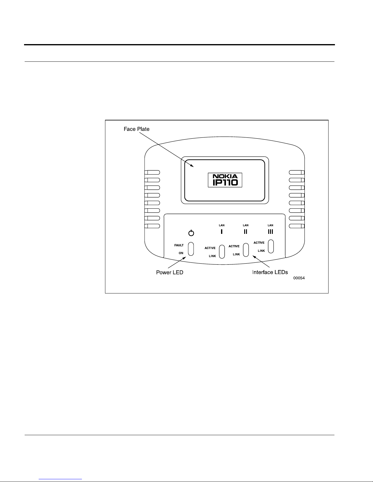
Figure 1-3 shows the top of an IP100 Series NAP.
Figure 1-3. Top vi ew of NAP
The three pairs of LEDs at the right of the unit correspond to the three
network connectors on the rear panel. They are labeled accordingly. The
top LED (ACTIVE) is ye llow and flashes on and off to indicate network
activity. The bottom LED (LINK) is green when there is a network
connection. Whe n there i s no networ k connect ion, the LED does not glow
at all.
6 IP100 Series Installation Guide

The LEDs on the left are labeled FAULT and POWER, with a universal
power symbol above the LEDs. The POWER LED is green when the unit
is receiving power. The FAULT LED is red when there is a system failure
or abnormal condition.
Bottom
Figure 1-4 shows the bottom of the NAP.
Features
Figure 1-4. Bottom view of NAP
IP100 Series Installation Guide 7

As Figure 1-4 indicates, the bottom of the unit has:
•
Four sets of ventilation slots
•
A rubber cushion at each corner, for placing the unit on a desk or
table or stacking NAPs on top of one another
•
Two keyhole slots for mounting the unit on a wall
8 IP100 Series Installation Guide

Site Requirements
Before installing the unit, ensure that the location where you intend to
place the unit conforms to the environmental specifications listed in
APPENDIX A,Technical Specifications
Site Requirements
.
WARNING:
North America, the cord set may be optional. If a
cord set is not provided, use a power cord rated at
6A, 250V, maximum 3 meters long, made of HAR
cordage and IEC fittings approved by the
country of end use.
WARNING:
battery i s incorr ectly pl aced. R eplace o nly with th e
same or equivalent type recommended by the
manufacturer. Dispose of used batteries according
to the manufacturer’s instructions.
For NAPs intended for shipment outside
There is danger of explosion if the
IP100 Series Installation Guide 9

10 IP100 Series Installation Guide

CHAPTER 2
Installing the Har dwar e
This chapter describes how to install an IP100 Series NAP and how to
connect it to a network. It also explains how to connect an external
modem to the NAP, as an alternative way of accessing the NAP from a
remote location.
IP100 Series Installation Guide 11

Placement of IP100 Series NAP
By Itself on Desk or Table
You can place an IP100 Series NAP on a desk, table, or other flat surface.
Stacking
You can stack up to three NAPs on top of one another (Figure 2-1).
Figure 2-1. Three NAPs stacked on top of one another (rear vie w)
12 IP100 Series Installation Guide
Place ment of IP10 0 Series NA P
Use the following procedures when stacking IP100 Series NAPs:
•
Do not remove the rubber feet on the bottom of an NAP. They keep
the NAPs from sliding against each other and ensure proper
ventilation and stability.
•
Provide suffi c ient clearance under the NAPs to allow air to move
through the components.
Wall Mounting
You can mount an IP100 Series NAP on a wall by using the two keyholes
slots on the back of the NAP. Whe n mounting the NAP on a wall, the
front panel should be at the top and the rear pan el at the bottom, with
connecting cables projecting downward from the rear panel.
Figure 2-2 shows how to mount the NAP on a wall.
WARNING:
Do not block any ventilation sl ot s on the
NAP. Internal components may overheat and be
damaged.
IP100 Series Installation Guide 13

Figure 2-2. Wall mounting of NAP
To mount the NAP on a wall follow these procedures:
Make sure you have the packet of mounting screws, anchor s, and
1.
stan doffs that come with the NAP.
Decide where to mount the NAP. For easy access mount the NAP at
2.
eye level and in a position where it is visible , isolated from other wall
mountings, and level.
Place marks where the two mounting screws should go. The distance
3.
from the center of one keyhole slot to the cente r of the other is 7.5
inches (19.05 cm).
Drill a quarter inch (0. 635 cm) hole at each mark, to accommodate
4.
the number 10 cr oss-he ad screws th at come with t he NAP (a long with
two anchors and two standoffs).
14 IP100 Series Installation Guide

Place ment of IP10 0 Series NA P
5.
Insert an anchor into each hole. Then place a standoff on the end of
each screw. Tur n the screw so that the screw protrudes one quarter
inch from the wall.
6.
Hold the NAP so that the screws are in the center of the keyholes.
Push down on the NAP so each screw is lodged firmly into the top of
each keyhole slot.
You can re-orient the face plate so it reads from left to right when facing
the wall-mounted NAP (rather than being upside down). To do this, use
the following procedures:
1.
Pull the face plate off the unit. The face place is attached with
adhesive.
2.
Rotate the face plate 180 degree s
3.
Place the face plate back on the unit. Press firmly so it sticks to the
unit.
NOTE :
permanent bond between the face plate and the unit approximately
four months from the date on which the face plate is initially
attached to the unit. After this point it will be impossible to re-orient
the face plat e.
The adhesive on the back of the face plate will form a
IP100 Series Installation Guide 15
Connecting the IP100 Series
To use an IP100 Series NAP you must:
Step 1—Connect the NAP to a power source
Step 2—Connect a console to the NAP
Step 3—Connect the NAP to a network
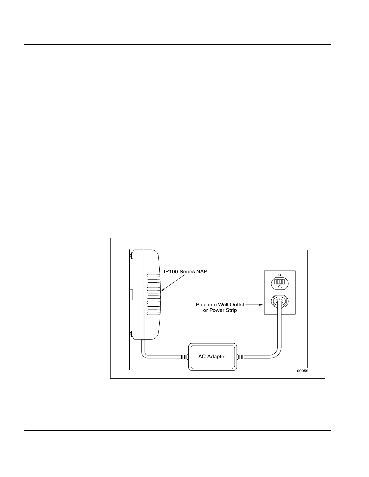
Step 1—Connecting the NAP to a Power Source
Plug the power cord that comes with the NAP into the 5-volt DC adapter.
Plug the other end into a
adapter into the POWER socket on the rear panel. The POWER LED on
the front panel should display green. Figure 2-3 shows the NAP
connected t o a powe r sou rc e.
3-wire, grounded
power source. Then plug the
Figure 2-3. NAP conne cted to power source
16 IP100 Series Installation Guide
 Loading...