

Page 1

© 2004 by Nokia
Nokia
ESB26 GigabitEthernet Switch
User Guide
Page 2

Document History
ISSUE DATE
ISSUED
COMMENTS
MN700004 Rev 01 15 Jan 2004 First draft.
Page 3

Table of Contents
PREFACE.................................................................................................................................................. A
1. INTRODUCTION..............................................................................................................................1
OVERVIEW........................................................................................................................................1
SPECIFICATIONS..............................................................................................................................3
2. GETTING STARTED .......................................................................................................................6
OVERVIEW........................................................................................................................................6
UNPACKING...................................................................................................................................... 6
FRONT PANEL .................................................................................................................................. 6
USING THE CLI TO CONFIGURE THE SWITCH.......................................................................... 7
PLANNING THE CONFIGURATION .............................................................................................. 9
BASIC CLI OPERATING CONVENTIONS ..................................................................................... 9
SPECIAL KEYS.................................................................................................................................. 9
CLI MODES...................................................................................................................................... 10
MESSAGES ......................................................................................................................................11
GETTING SYSTEM HELP ..............................................................................................................12
USING THE LIST COMMAND.......................................................................................................12
COMMAND HISTORY.................................................................................................................... 12
USING TELNET............................................................................................................................... 12
CONFIGURING THE DEVICE'S IP PARAMETERS..................................................................... 13
GENERAL COMMANDS ................................................................................................................14
VIEW MODE AND PRIVILEGED MODE .....................................................................................14
CONFIGURE MODE........................................................................................................................ 18
3. CONFIGURING A TELNET CONNECTION ............................................................................. 20
INTRODUCTION ............................................................................................................................. 20
CONFIGURING A TELNET SESSION...........................................................................................20
SWITCHING BETWEEN SESSIONS..............................................................................................24
4. USER PRIVILEGE LEVELS .........................................................................................................25
INTRODUCTION ............................................................................................................................. 25
SUPPORTED STANDARDS, MIBS AND RFCS............................................................................27
DEFAULT USER PRIVILEGE LEVELS CONFIGURATION....................................................... 27
CONFIGURING AND DISPLAYING USER PRIVILEGES...........................................................27
5. ETHERNET INTERFACE CONFIGURATION..........................................................................30
INTRODUCTION ............................................................................................................................. 30
SUPPORTED STANDARDS, MIBS AND RFCS............................................................................31
DEFAULT FAST AND GIGA ETHERNET PORTS CONFIGURATION ..................................... 31
CONFIGURING AND DISPLAYING FAST AND GIGA ETHERNET PORTS ........................... 32
RELATED COMMANDS.................................................................................................................44
6. PORT SECURITY ........................................................................................................................... 45
INTRODUCTION ............................................................................................................................. 45
CONFIGURING AND DISPLAYING PORT SECURITY SETTINGS.......................................... 45
7. LINK AGGREGATION GROUPS (LAGS).................................................................................. 49
INTRODUCTION ............................................................................................................................. 49
FEATURE OVERVIEW ................................................................................................................... 50
SUPPORTED STANDARDS, MIBS AND RFCS............................................................................52
PREREQUISITES ............................................................................................................................. 53
Page 4

DEFAULT LINK AGGREGATION CONFIGURATION ............................................................... 53
CONFIGURING AND DISPLAYING LAGS.................................................................................. 54
CONFIGURATION EXAMPLES.....................................................................................................58
8. TRAFFIC MONITORING..............................................................................................................66
INTRODUCTION ............................................................................................................................. 66
FEATURE OVERVIEW ................................................................................................................... 66
SUPPORTED STANDARDS, MIBS AND RFCS............................................................................69
PREREQUISITES ............................................................................................................................. 69
DEFAULT TRAFFIC MONITORING CONFIGURATION............................................................69
CONFIGURING AND DISPLAYING MONITOR SESSION......................................................... 70
CONFIGURATION EXAMPLES.....................................................................................................71
9. RESILIENT LINK...........................................................................................................................73
INTRODUCTION ............................................................................................................................. 73
CONFIGURING AND DISPLAYING A RESILIENT LINK.......................................................... 73
10. SNMP SERVER CONFIGURATION............................................................................................81
INTRODUCTION ............................................................................................................................. 81
CONFIGURING AND DISPLAYING THE SNMP SERVER SETTINGS..................................... 81
11. FORWARDING DATABASE (FDB)........................................................................................... 104
INTRODUCTION ........................................................................................................................... 104
MAC-TABLE ENTRY TYPES.......................................................................................................104
HOW ENTRIES ARE ADDED TO THE FDB............................................................................... 105
CONFIGURING AND DISPLAYING FDB SETTINGS...............................................................105
DESCRIPTION OF COMMANDS................................................................................................. 105
12. SPANNING TREE PROTOCOL (STP)......................................................................................110
INTRODUCTION ........................................................................................................................... 110
CONFIGURING AND DEBUGGING STP.................................................................................... 110
DISPLAYING PORT SPANNING-TREE TOPOLOGY SETTINGS............................................ 117
13. RAPID SPANNING TREE PROTOCOL (RSTP)...................................................................... 121
INTRODUCTION ........................................................................................................................... 121
SELECTION OF THE ROOT BRIDGE AND ROOT PORT......................................................... 122
SELECTION OF THE DESIGNATED BRIDGE AND DESIGNATED PORT............................ 122
CHANGING PORT STATES ......................................................................................................... 123
CONFIGURING AND DEBUGGING RSTP ................................................................................. 124
DISPLAYING PORT RAPID-SPANNING-TREE TOPOLOGY SETTINGS...............................134
14. MULTIPLE SPANNING TREE PROTOCOL (MSTP).............................................................139
INTRODUCTION ........................................................................................................................... 139
FEATURE OVERVIEW ................................................................................................................. 140
SUPPORTED STANDARDS, MIBS AND RFCS..........................................................................147
PREREQUISITES ........................................................................................................................... 148
DEFAULT MSTP CONFIGURATION.......................................................................................... 148
CONFIGURING AND DISPLAYING MSTP ................................................................................ 149
CONFIGURATION EXAMPLES...................................................................................................173
15. GARP MULTICAST REGISTRATION PROTOCOL (GMRP).............................................. 186
INTRODUCTION ........................................................................................................................... 186
FEATURE OVERVIEW ................................................................................................................. 186
SUPPORTED STANDARDS, MIBS AND RFCS..........................................................................187
PREREQUISITES ........................................................................................................................... 187
DEFAULT GMRP CONFIGURATION ......................................................................................... 187
CONFIGURING AND DISPLAYING GMRP............................................................................... 188
RELATED COMMANDS............................................................................................................... 189
16. GARP VLAN REGISTRATION PROTOCOL (GVRP)............................................................ 190
Page 5

INTRODUCTION ........................................................................................................................... 190
CONFIGURING AND DISPLAYING GVRP SETTINGS............................................................ 190
17. VIRTUAL LANS (VLANS)........................................................................................................... 194
INTRODUCTION ........................................................................................................................... 194
BENEFITS OF USING VLANS..................................................................................................... 194
VLAN TYPES................................................................................................................................. 194
USES OF TAGGED VLANS.......................................................................................................... 195
ASSIGNING A VLAN TAG........................................................................................................... 196
DESCRIPTION OF COMMANDS................................................................................................. 197
18. QUALITY OF SERVICE..............................................................................................................209
INTRODUCTION ........................................................................................................................... 209
FEATURE OVERVIEW ................................................................................................................. 209
SUPPORTED STANDARDS, MIBS AND RFCS..........................................................................216
DEFAULT QOS CONFIGURATION ............................................................................................216
CONFIGURING QUALITY OF SERVICE FEATURES ..............................................................218
RELATED COMMANDS............................................................................................................... 233
19. DHCP CLIENT ..............................................................................................................................234
DHCP OVERVIEW ........................................................................................................................ 234
THE ESB26 STARTUP PROCESS ................................................................................................ 235
THE DHCP NEGOTIATION PROCESS........................................................................................236
CONFIGURING THE DHCP CLIENT .......................................................................................... 239
CONFIGURATION EXAMPLE.....................................................................................................242
20. IGMP SNOOPING......................................................................................................................... 243
INTRODUCTION ........................................................................................................................... 243
JOINING A MULTICAST GROUP ...............................................................................................243
LEAVING A MULTICAST GROUP .............................................................................................243
IMMEDIATE-LEAVE PROCESSING........................................................................................... 244
IGMP SNOOPING COMMANDS.................................................................................................. 244
21. MULTICAST VLAN REGISTRATION (MVR) ........................................................................ 255
INTRODUCTION ........................................................................................................................... 255
DESCRIPTION OF COMMANDS................................................................................................. 256
22. TRANSPARENT LAN SERVICES (TLS)...................................................................................265
INTRODUCTION ........................................................................................................................... 265
FEATURE OVERVIEW ................................................................................................................. 265
SUPPORTED STANDARDS, MIBS AND RFCS..........................................................................266
PREREQUISITES ........................................................................................................................... 267
DEFAULT TLS CONFIGURATION ............................................................................................. 267
CONFIGURING AND DISPLAYING TLS ...................................................................................267
23. SOFTWARE UPGRADE AND REBOOT OPTIONS................................................................ 272
OVERVIEW....................................................................................................................................272
DESCRIPTION OF COMMANDS................................................................................................. 272
24. FILE SYSTEM FOR CONFIGURATION SCRIPT FILES...................................................... 282
INTRODUCTION ........................................................................................................................... 282
SCRIPT-FILE COMMANDS..........................................................................................................282
25. STATUS MONITORING, STATISTICS AND GENERAL COMMANDS ............................. 289
OVERVIEW....................................................................................................................................289
DESCRIPTION OF COMMANDS................................................................................................. 290
26. REMOTE MONITORING............................................................................................................ 304
INTRODUCTION ........................................................................................................................... 304
FEATURE OVERVIEW ................................................................................................................. 304
Page 6

SUPPORTED STANDARDS, MIBS AND RFCS..........................................................................305
STATISTICS MONITORING ........................................................................................................306
RMON ALARMS............................................................................................................................ 307
27. PERIODIC MONITORING .........................................................................................................312
INTRODUCTION ........................................................................................................................... 312
FEATURE OVERVIEW ................................................................................................................. 312
SUPPORTED STANDARDS, MIBS AND RFCS..........................................................................314
DEFAULT PERIODIC MONITORING CONFIGURATION........................................................315
CONFIGURING AND DISPLAYING PERIODIC MONITORING .............................................316
CONFIGURATION EXAMPLES...................................................................................................326
RELATED COMMANDS............................................................................................................... 328
28. LOGGING SYSTEM TRAP MESSAGES TO THE NVRAM ..................................................329
INTRODUCTION ........................................................................................................................... 329
CONFIGURING THE TRAP LEVEL FOR STORED SYSTEM MESSAGES.............................329
CONFIGURING THE MESSAGE FORMAT................................................................................ 329
NVRAM SYSTEM-TRAP LOGGING COMMANDS...................................................................330
29. NVRAM CONFIGURATION HISTORY....................................................................................333
INTRODUCTION ........................................................................................................................... 333
HISTORY LOG FORMAT AND GENERATION ......................................................................... 333
CONFIGURING HISTORY SETTINGS........................................................................................ 333
DISPLAYING THE CONFIGURATION HISTORY..................................................................... 334
30. CONFIGURING THE WATCHDOG FEATURES....................................................................337
OVERVIEW....................................................................................................................................337
ACCESSING WATCHDOG MODE .............................................................................................. 337
CONFIGURING THE RESET-LOOP DETECTION FEATURE .................................................. 338
CONFIGURING THE SNMP REQUEST FAILURE DETECTION FEATURE...........................339
CONFIGURING THE APPLICATION SUSPENSION DETECTION FEATURE....................... 340
DISPLAYING THE WATCHDOG CONFIGURATION............................................................... 341
31. NTP CLIENT DESCRIPTION..................................................................................................... 342
INTRODUCTION ........................................................................................................................... 342
THE NTP TIMESERVER COMMANDS.......................................................................................342
WHY USE NTP PROTOCOL ?...................................................................................................... 343
CONFIGURING AND DISPLAYING NTP SERVER SETTINGS............................................... 343
MD5 AUTHENTICATION.............................................................................................................345
RUNNING THE NTP SERVER ..................................................................................................... 346
EXAMPLES .................................................................................................................................... 347
CONFIGURATION EXAMPLE.....................................................................................................347
CONFIGURING DAYLIGHT SAVING TIME (DST) ..................................................................348
32. REMOTE AUTHENTICATION DIAL-IN USER SERVICE (RADIUS) ................................ 351
INTRODUCTION ........................................................................................................................... 351
BINOS RADIUS FEATURES ........................................................................................................ 351
DESCRIPTION OF COMMANDS................................................................................................. 352
USING RADIUS TO CONFIGURE LOGIN AUTHENTICATION.............................................. 354
A RADIUS CONFIGURATION EXAMPLE ................................................................................. 355
33. SECURE SHELL (SSH) ................................................................................................................ 357
INTRODUCTION ........................................................................................................................... 357
SOME SECURITY CONSIDERATIONS ...................................................................................... 357
COMMANDS FOR MANAGING THE SSH SERVER.................................................................358
SUPPORTED CLIENTS................................................................................................................. 359
SUPPORTED STANDARDS..........................................................................................................359
34. 802.1X PORT-BASED AUTHENTICATION ............................................................................. 360
INTRODUCTION ........................................................................................................................... 360
Page 7

FEATURE OVERVIEW ................................................................................................................. 360
SUPPORTED STANDARDS, MIBS AND RFCS..........................................................................363
DEFAULT 802.1X CONFIGURATION.........................................................................................364
CONFIGURING AND DISPLAYING 802.1X...............................................................................365
CONFIGURATION EXAMPLE.....................................................................................................376
RELATED COMMANDS............................................................................................................... 376
35. BUILT-IN SELF TEST (BIST)..................................................................................................... 378
OVERVIEW....................................................................................................................................378
STARTUP EXECUTION OF BIST ................................................................................................ 378
BIST COMMANDS ........................................................................................................................ 379
36. DIAGNOSTIC TESTS................................................................................................................... 382
ESB26 DIAGNOSTICS-RELATED COMMANDS.......................................................................382
THE DIAGNOSTICS-RELATED COMMANDS .......................................................................... 382
37. DNS RESOLVER........................................................................................................................... 390
INTRODUCTION ........................................................................................................................... 390
FEATURE OVERVIEW ................................................................................................................. 390
SUPPORTED STANDARDS, MIBS AND RFCS..........................................................................391
DEFAULT DNS RESOLVER CONFIGURATION....................................................................... 392
CONFIGURING AND DISPLAYING DNS RESOLVER............................................................. 392
CONFIGURATION EXAMPLE.....................................................................................................393
RELATED COMMANDS............................................................................................................... 393
APPENDIX: LOADER, SYSLOADER AND DUAL BOOT ................................................................. I
OVERVIEW.........................................................................................................................................I
LOADER..............................................................................................................................................I
SYSLOADER AND DUAL BOOT ..................................................................................................IX
Page 8

MN700004 Rev 01 a
Preface
This guide provides the required information to setup and configure the ESB26 switch,
firmware version 3.3.0. It is intended for network administrators who are responsible for
installing and setting up network equipment. It assumes a basic working knowledge of the
following:
•
Local area networks (LANs)
•
Ethernet concepts
•
Ethernet switching and bridging concepts
•
Routing concepts
•
Internet Protocol (IP) concepts
If the information in the Release Notes that are shipped with your unit differs from the
information in this guide, follow the Release Notes.
Conventions Used in This Guide
The syntax of CLI command lines, explained in "Basic CLI Operating Conventions" and the
further topics and discussed throughout this guide, is represented by the following general
format:
device-name>keyword(s) [parameter(s)] ... [keyword(s)] [parameter(s)]
OR
device-name[ (config ...)]#keyword(s) [parameter(s)]
... [keyword(s)] [parameter(s)]
where:
•
The angle bracket (>) is the CLI prompt symbol in View mode.
•
The pound symbol (#) is the CLI prompt symbol in all other modes.
•
The left part, up to and including the prompt symbol represents the command prompt
displayed by the computer. In this part:
device-name stands for the name of the switch (e.g. ESB26).
The optional expression “(config)” or “(cfg ...)” – including the parentheses –
appears on the screen exactly as in the manual.
The part following the prompt symbol represents the users command. In this
Page 9

Preface
MN700004 Rev 01
b
part:
> keyword(s), in boldface characters, stands for one or more standard CLI
command keywords. The first keyword may optionally be preceded by no
to indicate a negation of the command.
> parameter(s) may be one or more optional or requisite values, depending
on the requirements of the specific command. They are represented by
slanted characters.
> In this guide, keywords and parameters may be separated by vertical OR
bars (|). The OR bars indicate an exclusive-or choice among a group of
selectable entities separated by these symbols.
> Parentheses and braces may be used in this guide to enclose selectable
entities – for the purpose of clarification.
Acronyms Used in This Guide
L3 OSI Layer 3 requirements
DHCP Dynamic host configuration protocol
Downlink The Ethernet links connecting to equipment that perform host data processing.
GARP Generic Attribute Registration Protocol
GMRP Group Multicast Registration Protocol
GVRP GARP VLAN Registration Protocol
MAC Media Access Control
MIB Management information base
pps Packets per second
SNMP Simple network management protocol
STP Spanning Tree Protocol
RSTP Rapid Spanning Tree Protocol
Uplink The Ethernet links connecting to another switch or router.
UTP Unshielded twisted pair
VLAN Virtual Local Area Network
10Base-T 10Mbit/s Ethernet link that works over standard UTP copper cabling.
Page 10

Preface
MN700004 Rev 01
c
100Base-TX
1000Base-T
1000Base-SX
100Mbit/s Ethernet link that works over standard UTP copper cabling.
1000Mbit/s Ethernet link that works over standard UTP copper cabling.
1000Mbit/s Ethernet link that works over optical, 850nm multimode cabling.
Summary of Version 3.3.0 Features
The Version 3.3.0 includes the following features:
●
VLANs (Virtual local area networks) including support for IEEE 802.1Q and IEEE
802.1p
●
VLAN aggregation
●
STP (Spanning Tree Protocol) (IEEE 802.1D)
●
RSTP (Rapid Spanning Tree Protocol) (IEEE 802.1w)
●
MSTP (Multiple Spanning Tree Protocol) (IEEE 802.1s)
●
QoS (Quality of Service)
●
IGMP snooping to control IP multicast traffic.
●
GMRP (GARP Multicast Registration Protocol)
●
GVRP (GARP VLAN Registration Protocol)
●
MVR (Multicast VLAN Registration)
●
Console CLI (Command-line Interface) connection
●
Telnet CLI connection
●
SNMP (Simple Network Management Protocol) v1, v2c and v3 support
●
RMON (Remote Monitoring)
●
Traffic mirroring for all ports
●
DHCP Client
●
Backpressure and flow control support
●
802.3x flow control for full-duplex links
●
Link Aggregation (LAG) for increased bandwidth without requiring expensive
hardware upgrade
●
Link Aggregation Control Protocol (LACP) providing dynamic LAGs
●
Console timeout value
●
Remote logging
●
Remote time synchronization protocol (rfc867, rfc868).
●
SSH
Page 11

Preface
MN700004 Rev 01
d
●
RADIUS
●
CLI user privilege levels
●
Resilient link for port redundancy
●
Script file system
●
Up to 1.7 MB size of the configuration file
●
More accurate CPU utilization measurement
●
Inform requests for SNMPv2c
●
MAC address per port in BPDU for xSTP
●
Enhanced DHCP boot process:
●
Startup configuration integrity check
●
Option to save downloaded file to the internal Flash memory
●
Image file upload
●
Enhanced password security (passwords are saved in the internal Flash memory and
not in the running config, startup or script files.)
● Cable crossover support
Page 12

MN700004 Rev 01 1
1. Introduction
Overview
ESB26 is an integrated Ethernet switch based on DX200 hardware platform. The ESB26
features a total of 26 Ethernet ports of types and placements as follows:
Port Placement Connector Traffic
20 full duplex 10/100Base
T/TX Ethernet ports
back panel AMP 2mm Z-pack
connectors compatible
downlink
2 full duplex 10/100Base
T/TX Ethernet ports
front panel RJ45 downlink/uplink
2 1000Base-T ports front panel RJ45 downlink/uplink
2 1000Base-SX ports front panel LC uplink
ESB26 contains also one RS-232 interface (RJ45) on the front panel for management
purposes.
The two 1000Base-T ports support all the 10/100/1000 Mbit/s link speeds. Speed mixing is
supported, too, e.g. it is possible to use one of the 1000Base-T ports in gigabit mode while the
other runs in 100Mbit mode.
The intended use of the ESB26 is to collect the Ethernet links of different computer units and
preprocessor units of DX200-based network elements, and allow access to them from the
upper levels. The ESB26 can be used in all M98F DX200 based network elements. The
ESB26 can be assembled into a place of ESB20/ESB20-A by using the existing cabling.
NOTE
The ESB26 is designed to operate in forced cooling M98F only.
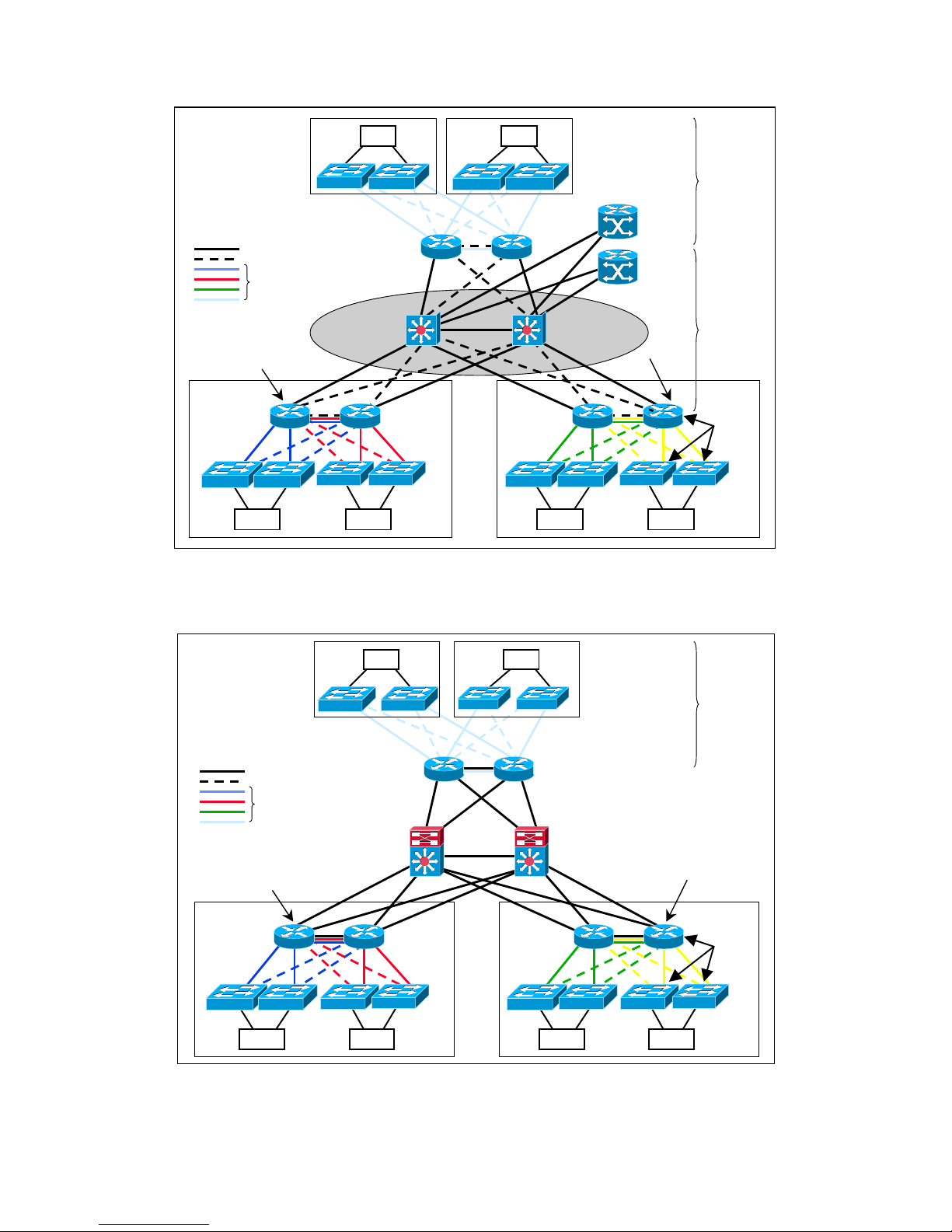
The two graphics below represent two examples of operational environments for the ESB26.
As presented, the ESB26s are used to collect traffic from/to different computer units and
preprocessor units and forward it towards 3rd party L3 switches. It is important to note that
VLAN-technology is used in order to divide the different units into several broadcast
domains. It must also be noted that redundant paths do exists and Rapid STP (as according to
IEEE 802.1w) is used in order to avoid loops.
Page 13
1. Introduction
MN700004 Rev 01
2
OSR
OSR
IPET
IPET
IPET
IPET
TGSU
TGSU
IPET-
cabinet
IPET-
cabinet
Legend:
Forwarding
Blocked
VLANs
Rapid-
STP
Rapid-
STP
3550
3550
3550
3550
Rapid-
STP
OSRs used as L2-
devices
ESB26
ESB26
ESB26 ESB26
ESB26
ESB26
ESB26 ESB26
ESB26
ESB26
ESB26
ESB26
3550
3550
GSR
GSR
Cisco 3550s
or
ESB26s
Cisco 3550s
or ESB26s
Cisco 3550s
or ESB26s
Figure 1-1 Example of Operational Environment for the ESB26 with L2 OSRs
OSR
OSR
IPET
IPET
IPET
IPET
TGSU
TGSU
IPET-cabinet
IPET-cabine
t
Legend
Forwarding
Blocked
VLANs
Rapid-
STP
3550
3550
3550
3550
3550
3550
ESB26
ESB26 ESB26 ESB26 ESB26 ESB26 ESB26 ESB26
ESB26
ESB26
ESB26
ESB26
Rapid-
STP
OSRs used as L3-
Cisco 3550s or
ESB26s (possible
with L3 software)
Cisco 3550s or
ESB26s (possible
with L3 software)
Cisco 3550s or
ESB26s (possible
with L3 software)
Figure 1-2 Example of Operational Environment for the ESB26 with L3 OSRs.
Page 14

1. Introduction
MN700004 Rev 01
3
The switch is managed via BiNOS Command Language Interface (CLI) commands typed in
by the user by either of the following means:
•
By direct connection, through a VT-100 compatible terminal connected to the
console port on the unit’s front panel;
•
Remotely, using telnet over a TCP/IP communication network.
Specifications
Compliance
• IEEE802.3
• IEEE802.1d
• IEEE802.3X
• IEEE802.1q
• IEEE802.1w
• IEEE802.1s
• IEEE802.3ad
Switching Characteristics
Bridging
Address table:
Forwarding Rate:
Internal Bandwidth (max):
Buffers Memory:
Priority Queuing:
Virtual LAN:
Per IEEE 802.1d / 802.1w /802.1s spanning tree.
16 K MAC address per switch.
148,800 packets-per-second maximum for 100Base ports.
1,488,000 packets-per-second maximum for 1000Base ports.
5.3 Gbps (Full Duplex).
32 Mbytes
8 Queues per port, provides CoS per 802.1p
Port Based VLAN per 802.1q.
Up to 4094 VLAN groups can be defined.
GVRP protocol support.
Port Aggregation: Up to 7 static or dynamic LAGs can be defined.
In-Band: SNMP, TELNET,
Supported MIBs: MIB-II, BRIDGE MIB (RFC-1493), PRIVATE MIB, RMON MIB (Group
I,2,3,9)
Page 15

1. Introduction
MN700004 Rev 01
4
Local:
For initial configuration, EIA-232 protocol, RJ-45 console connector
on the front panel, VT100 compatible
Management
Software download: Via TFTP (Server application)
Monitoring: Port mirroring for sniffer connection.
Max. configuration file size: 1.7 MB
Indicators
General: Operation Indicator. A single two-color LED (Green/Red)
• Green: the unit is operational.
• Red: during power up and in faulty condition.
• Blinking orange: when no image software is loaded.
• Off: power is off.
Physical Characteristics
Dimensions: 233.4x220mm with PCB thickness of 1.6mm and spacing of 20.34mm (4T)
Supported chassis
models:
CC3C-ACC4C-ACM2C-ALASWC-AIPETC-A
Environmental Characteristics
Operating Temperature: According to Nokia Environmental Specification (Commercial Range
0-70°C)
Humidity: Complying to Nokia Environmental Specification
Power Characteristics
Voltage:
Power Consumption:
+3.3Vand +5V (±5% voltage tolerances)
Less than 25 W
Ex-Factory Default Settings
IP Address: 192.168.0.5
Page 16

1. Introduction
MN700004 Rev 01
5
Subnet mask: 255.255.255.128
Default gateway: 192.168.0.10
Password: nokia
Telnet: enabled
SNMP: disabled
RMON: enabled
802.1p priority recognition: enabled
802.1q tagging: disabled on the default VLAN
Forwarding database aging
period:
300 seconds (5 minutes)
GVRP: disabled
GMRP: disabled
SSH: disabled
LACP: disabled
LAN ports status: enabled
Port auto negotiation: enabled
Port mirroring: disabled
VLANs: disabled
Rapid STP: disabled
DHCP: enabled
Hot-Swap
The card can be inserted and removed while power is applied to the IPA2800 chassis. Before
removing the card, press the Reset button twice within two seconds. This will disconnect
power from the card for 20 seconds. The LED will turn off, indicating that the card can be
safely removed.
Page 17
MN700004 Rev 01 6
2. Getting Started
Overview
ESB26 installation consists of inserting the card into the appropriate slot in the system,
turning the unit power on, and setting the IP Address in order to enable remote management.
All other management procedures may be performed remotely via Terminal Interface
management applications that are integrated into the unit.
This chapter describes how to install the unit, perform initial setup, use Terminal Interface
management applications, and how to perform basic switch operations.
Unpacking
After unpacking:
•
Verify that the ESB26 unit has not been damaged during shipment.
•
It is recommended that you keep the shipping package until the unit has been
installed and verified as being fully operational. As all electronic devices with
static sensitive components, ESB26 should be handled with care.
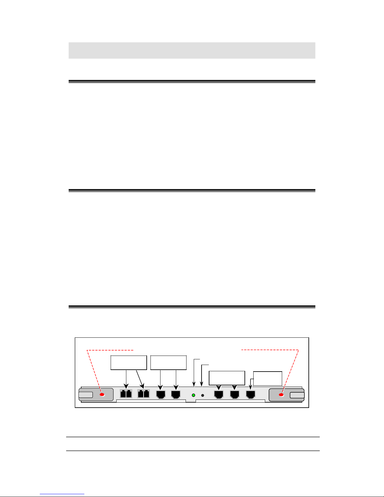
Front Panel
SER1
OPR
RST
ETH2
ETH1
Operation indicator
Reset button
Serial
connector
1000Base T
ports
Open tabs outwards to insert or extract card
ETH4
ETH3
B
A
ETH6
ETH5
1000Base SX
ports
10/100Base
T/TX ports
Figure 2-1 ESB26 Front Panel
Table 2-1 ESB26 Front Panel Components
ETH1, ETH2 Two 1000Base SX ports interface connectors
Page 18

2. Getting Started
MN700004 Rev 01
7
ETH3, ETH4 Two 1000Base T ports interface connectors
ETH5, ETH6 Two 10/100Base T/TX ports interface connectors
OPR
Operation Indicator. A single two-color LED (Green/Red)
• Green: the unit is operational
• Red: during power up and in faulty condition.
• Blinking orange: when no image software is loaded.
• Off: power is off.
RST Local Reset and Hotswap button.
To perform Hotswap, press twice within two seconds before removing the card.
Power will be turned off for 20 seconds during which the card may be removed
safely.
SER1 RJ45 console connector used for initial configuration.
TX – Pin 2 (Going out of the switch)
RX – Pin 5 (Going into the switch)
GND – Pin 3
GND – Pin 4
Using the CLI to Configure the Switch
The configuration program uses a CLI (Command Line Interface) that enables you to start
using the switch quickly and without extensive background knowledge. It does this by
prompting you for the information required to perform basic configuration procedures.
Using the CLI, you will be able to do the following:
•
Establish host names and interfaces
•
Enable transparent Ethernet bridging
•
Configure Layer 2 switch protocols (GVRP, GMRP, Spanning Tree, etc.)
•
Configure VLANs
System parameters are stored in a non-volatile memory. They have to be set up only once
during initial setup.
Getting Started with the CLI
Configuration of the switch is done by connecting a VT-100 (or compatible terminal) to the
card RJ-45 (Console) connector.
The CLI operates automatically when you power on the switch. Before you start using the
CLI, you must do the following:
Page 19

2. Getting Started
MN700004 Rev 01
8
Step 1.
Insert the device into its chassis slot.
Step 2.
Attach an RS-232 ASCII terminal to the RJ-45 (SER1) connector (See Figure 2-1).
Step 3.
Configure the terminal to operate at:
•
Emulation mode: VT-100 mode (default mode)
•
9600 bps
•
8 data bits
•
1 stop bit
•
No parity
•
No flow control
25 lines and 80 columns window size
Step 4.
Establish a session with the unit and power on the unit. After a few seconds, the
following is displayed on the terminal screen:
Press any key to stop auto-boot...
0
Verifying validity of primary application.....OK
Start primary application...
BUILT-IN SELF TEST
-----------------CPU Core Test : Passed
CPU Notify RAM Test : Passed
CPU Interface Test : Passed
Testing Switch Core : Passed
On-board Power Test : Passed
////////////////////////////////////////////////////////////////////////
// //
// N O K I A //
// //
// //
// Switch model : NOKIA ESB26 //
// SW version : 3.2.89 ER created Dec 17 2003 - 11:32:40 //
// //
////////////////////////////////////////////////////////////////////////
User Access Verification
Password:
Step 5.
Enter your password, which is nokia
by default. The device-name> prompt is
displayed, allowing you to begin the configuration process.
Page 20

2. Getting Started
MN700004 Rev 01
9
If the password has been lost or cannot be configured, please contact Nokia support.
Planning the Configuration
Before starting the configuration process, determine the following:
•
The protocols you plan to use and their specific parameters
•
The types of interfaces installed: Ethernet or Serial
•
Whether or not you plan to use bridging
Basic CLI Operating Conventions
Entering commands at the CLI prompt and then pressing the Return key initiates CLI
commands. Based on user input, the CLI returns various data in response.
You type all commands on one line and then press <Enter>. The CLI response is displayed on
your screen.
You can use abbreviated commands provided they are unique. For example, enter the letters
sho
for the show command.
Certain commands display multiple screens with this prompt at the bottom of the screen:
--More--
Press on the space bar to continue.
Special Keys
Table 2-2 summarizes special keys available at the CLI prompt.
Table 2-2 CLI Entry Keys
Key Action
Backspace Erase characters
Ctrl-U Delete line
Ctrl-W Erase the last word
Exit Escape current mode and go to previous mode
Page 21

2. Getting Started
MN700004 Rev 01
10
Key Action
Ctrl-F Move forward one character
Ctrl-B Move backward one character
Esc and then B Move bacward one word
Esc and then F Move forward one word
Ctrl-A Move to the beginning of the line
Ctrl-E Move to the end of the line
Ctrl-H Delete the character before point
Ctrl-D Delete the character after point
Esc and then D Forward kill word
Ctrl-K Kill to the end of the line
Ctrl-C Interrupt current input and moves to the next line
Ctrl-N Move down to next line in the history buffer
Ctrl-P Move up to previous line in the history buffer
Tab Use command line completion by pressing the Tab key.
?
Typing
?
at the beginning of the line, generates a list of available commands.
Typing ?
at any point within the line will show possible completions.
CLI Modes
There are several CLI modes and associated prompt levels. The prompt is the string that
appears after the host name (
ESB26
by
default). The following are the main CLI modes:
View Mode (user-level)
The View mode allows viewing capabilities only. Its prompt is an angle bracket (>):
device-name>
View mode is password protected. The password is nokia by default. You can change this
password by using the password command in global Configuration mode.
Privileged Mode
The Privileged mode allows advanced viewing unit capabilities and limited configuration
capabilities. Its prompt is a pound symbol (#):
Page 22

2. Getting Started
MN700004 Rev 01
11
device-name#
By default, Privileged mode is not password protected. However, you can configure password
protection by using the password command from the Configure prompt.
To access Privileged mode from View mode, use the enable command. (That is why this
mode is also referred as "Enable" mode.)
Configure Mode
The Configure mode allows full configuration capabilities. Its prompt is displayed as follows:
device-name(config)#
Additional information can be displayed inside the parentheses, before the pound symbol, to
indicate the present configuration mode.
For example:
device-name(cfg protocol)#
indicates that you are in the Configure Protocol mode.
To access Configure mode from Privileged mode, use the configure terminal command.
Startup Modes
There are also two separate special startup modes, called "Loader" and "Sysloader". They are
designed mainly for techical support purposes and are not user-configurable. Both of them are
covered in detail in the Appendix.
Messages
Several messages may be issued in response to incorrect entries (e.g., wrong syntax, or
incomplete commands). The following are some of these messages:
% unknown command
displayed when you enter a string that is not a command.
% command incomplete
indicates that you entered a valid command but failed to enter all its required parameters.
Press the <Tab> key to display the possible options.
Other messages include:
Page 23

2. Getting Started
MN700004 Rev 01
12
% ambiguous command.
% port 9 invalid, valid val: 1..8
Getting System Help
For system help, enter ? or the letter l (for "list") to display a list of commands that are
available at either the user-level or the privileged-level CLI prompt.
To get more information about certain commands, type ? after the command. For more
information, see the lists of commands that are displayed after entering ?
Using the List Command
The
list
command displays a complete list of the commands relevant to the prompt displayed.
If the list is larger than can be displayed on your screen, the following is displayed.
--more--
Command History
A memory buffer in the ESB26 retains the last 20 commands you entered.
Using Telnet
Any workstation with a telnet facility should be able to communicate with the ESB26 over a
TCP/IP network. Up to five active telnet sessions can access the ESB26 concurrently. The
telnet session will be disconnected after a specified time of inactivity.
Before you can start a telnet session, you must set up the IP parameters described in the
Configuring the Device's IP Parameters section. Telnet is enabled by default.
To open the telnet session, you must specify the IP address of the device that you want to
manage. Check the user manual supplied with the telnet facility if you are unsure of how to do
this.
Once the connection is established, you will be prompted to log in. VT100 emulation and
VT100 keys must be used.
Page 24

2. Getting Started
MN700004 Rev 01
13
Configuring the Device's IP Parameters
To manage the ESB26 by a telnet connection or by using an SNMP Network Manager, you
must first configure the IP parameters of the ESB26 switch and the default gateway.
Step 1.
Change to Global Configuration mode by typing
configure terminal
at the Privileged
mode prompt.
The DHCP client is enabled by default; therefore, to configure a static IP address, you
should first disable the DHCP client.
Step 2.
To disable the DHCP client, use the following command in Global
Configuration mode:
Command Syntax
device-name(config)#no ip address dhcp
Step 3.
To set the IP address, use the following command in Global Configuration mode:
Command Syntax
device-name(config)#ip address A1.B1.C1.D1 [/M|A2.B2.C2.D2] [dhcp
A3.B3.C3.D3]
Argument Description
A1.B1.C1.D1 IP address of the configured IP interface.
/M Subnet mask of the configured IP interface (in the range 1-30).
A2.B2.C2.D2 Subnet mask of the configured IP interface.
dhcp Use dhcp client
A3.B3.C3.D3
Request IP address A.B.C.D
Example
device-name(config)#ip address 100.1.2.3/16
device-name(config)#ip address dhcp 9.0.0.1
The IP address of the ESB26 becomes 100.1.2.3 in network 100.1.0.0
Step 4.
Set the default gateway IP address as
follows:
Command Syntax
device-name(config)#ip route {destination-address
netmask|destination-prefix} A.B.C.D [<distance>]
device-name(config)#no ip route {destination-address
netmask|destination-prefix} A.B.C.D [<distance>]
Page 25

2. Getting Started
MN700004 Rev 01
14
Argument Description
destination-address
Route’s IP destination address, in
A.B.C.D
format, used in conjunction with
netmask to define a network address.
netmask
Destination network mask, in
A.B.C.D format, used in conjunction with
destination-address.
destination-prefix
Route’s destination prefix, in
A.B.C.D/M format.
A.B.C.D
IP gateway address in
A.B.C.D
format.
distance (Optional). Distance assigned for this route, in the range <1-255>.
Example
device-name(config)#ip route 0.0.0.0/0 100.1.1.1
The default gateway IP address is 100.1.1.1 in network 100.1.0.0
General Commands
Table 2-3 shows the commands you can use at all times, regardless of the type of prompt
displayed.
Table 2-3 General Commands
exit Escape current mode and go to previous mode
help Display help information
no Negate a command or set its defaults
quit Escape current mode and go to previous mode
View Mode and Privileged Mode
Table 2-4 summarizes the Privileged mode commands. The enable command is available
only in View mode and is used to access Privileged mode. All other commands listed in the
table are available in Privileged mode. The show command and the terminal command are
available both in View and in Privileged mode.
Page 26

2. Getting Started
MN700004 Rev 01
15
Table 2-4 Privileged Mode Command Summary
clear Clears a specified entry or entries from one of the tables (the command is available only
in Privileged mode).
configure Configuration from VTY interface (the command is available only in Privileged mode).
copy Transfers file to the target base (the command is available only in Privileged mode).
debug Enables the debugging options
disable Exits from Privileged mode (the command is available only in Privileged mode).
enable Enters Privileged mode (the command is available only in View mode).
reload Halts and performs a cold restart (the command is available only in Privileged mode).
self-test Shows built-in test results (the command is available only in Privileged mode).
session Telnet session commands (the command is available only in Privileged mode).
show Shows running system information.
telnet Start telnet client (the command is available only in Privileged mode).
terminal Terminal configuration setup.
ping Sends ICMP echo messages (the command is available only in Privileged mode).
traceroute Trace routing path (the command is available only in Privileged mode).
who Displays who is on VTY.
write
scp-image
swap
Writes configuration to memory, network or terminal (the command is available only in
Privileged mode).
Secure copy.
Swaps the primaryand the secondary applications.
Accessing Privileged Mode
enable
The enable command, in View mode, allows accessing the Privileged mode. After entering
this command, the prompt symbol changes from an angle bracket to a pound symbol (#).
Command Syntax
device-name>enable
Example
device-name>enable
device-name#
Page 27

2. Getting Started
MN700004 Rev 01
16
Description of View and Privileged Mode Commands
configure terminal
The configure terminal command, in Privileged (Enable) mode, allows accessing the Global
Configure mode, for configuration of VLANs, interfaces, resilient link, etc.
Command Syntax
device-name#configure terminal
Example
device-name#configure terminal
device-name(config)#
terminal length
The terminal length command, in View or Privileged (Enable) mode, specifies the number of
lines the CLI displays, in response to a command, before displaying the
--More--
string.
Command Syntax
device-name#terminal length
show ip
The show ip command, in View or Privileged (Enable) mode, displays the IP address of the
ESB26 and its subnet mask.
Command Syntax
device-name#show ip
Example
device-name#show ip
IP-ADDR : 212.29.220.136 NET-MASK : 255.255.255.192
device-name#
show ip arp
The show ip arp command, in View or Privileged (Enable) mode, displays Address
Resolution Protocol information.
Command Syntax
device-name#show ip arp
Example
device-name#show ip arp
show ip arp
======+==================+=================+========+========+
# | IP Address | MAC |Age(min)| if |
Page 28

2. Getting Started
MN700004 Rev 01
17
------+------------------+-----------------+--------+--------+
0 | 192.168.0.4 |00:40:95:30:12:2e| 2 | sw0 |
1 | 192.168.0.22 |00:40:95:32:76:04| 1 | sw0 |
2 | 192.168.0.44 |00:40:95:30:5e:e1| 1 | sw0 |
device-name#
traceroute
The traceroute command, in Privileged (Enable) mode, displays the routing path from the
ESB26 to the targeted IP address. This command can help determine how routing is done in
the network. The execution of the command can be stopped by pressing the ESC key.
Command Syntax
device-name#traceroute A.B.C.D [TTL] [TIMEOUT]
Argument Description
A.B.C.D The IP address to be traced.
TTL
Defines the numbers of routers that allow the traceroute command to pass when it looks
for the specified IP address.
TIMEOUT
Defines the length of time (in seconds) that an answer to a traceroute request can be
received (default is 2 seconds).
ping
The ping command, in Privileged (Enable) mode, allows to ping a unit.
Command Syntax
device-name#ping A.B.C.D [NUMBER] [TIMEOUT] [DELAY] [LENGTH]
Argument Description
A.B.C.D The destination IP address.
NUMBER Number of echo packets to send (default 5).
TIMEOUT Wait for response in seconds (default 2 seconds).
DELAY Delay between packets in seconds (default immediately).
LENGTH Size of the ICMP echo packet (default 100).
Example
To send 5 pings of 80 bytes with a 30-second wait for reply and a 20-second delay between
pings, enter the following command:
device-name#ping 212.29.220.136 5 30 20 80
sending 5, 80-byte icmp echos to 212.29.220.136, timeout is 1 seconds: !!!
The exclamation points are displayed at the end of each successful packet. The CLI prompt is
displayed on your screen when the entire ping sequence has been completed. The execution of
the command can be stopped by pressing the ESC key.
Page 29

2. Getting Started
MN700004 Rev 01
18
Configure Mode
The Configure mode allows full configuration capabilities. Its prompt is as follows:
device-name(config)#
Additional information can be displayed inside the parentheses, before the pound symbol, to
indicate the present Configuration Mode.
For example:
device-name(cfg protocol)#
indicates that you are in the Configure Protocol mode.
Accessing Global Configuration Mode
To access Global Configuration mode:
Step 1.
Type the enable command at the EXEC prompt:
device-name>enable
The prompt indicates entry into Privileged mode:
device-name#
Step 2.
Type configure terminal
at the Privileged-level prompt. The prompt following this
command indicates entry into the global Configuration mode.
device-name(config)#
Configuration Command Types
Configuration commands are categorized as follows:
Global configuration
commands
Defines system-wide parameters.
Interface configuration
commands
Defines the characteristics of an interface (for example, a Serial or
Ethernet interface). To access these commands, use the interface
command in global Configuration mode.
Line subcommands Defines the characteristics of a serial line. These commands must be
preceded by a line command.
Observe the following guidelines when you execute configuration commands:
•
You can enter configuration subcommands in uppercase letters, lowercase
letters, or both. You can also abbreviate all commands and other keywords to
the least number of characters that uniquely identify the command.
•
To add a comment, begin the line with an exclamation point (!). Comments
do not affect command processing.
Page 30

2. Getting Started
MN700004 Rev 01
19
Configuration Mode Sub-Modes
Configuration mode has several sub-modes, each used to configure various entities in the
ESB26. Each mode has its own unique prompt and list of commands. The following are the
Configuration mode sub-modes.
Table 2-5 Configure Mode Sub-Modes Summary
Mode Description Prompt (following device-name)
Line VTY Configuration Configures the VTY sub-mode, to allow
accessing the ESB26 via telnet.
(config-VTY)#
Interface Configuration Configures interface ports or port
groups.
(config-if 1/1/1)#
or
(config-if-group)#
VLAN Configuration Configures Virtual LANs (VLANs).
(config vlan)#
Protocol Configuration Configures protocols.
(cfg protocol)#
Resilient Link Configuration Configures resilient links.
(config-resil-link N)#
File system Configuration For script file system management.
(config script-file-system)#
Monitor Configuration Configures monitoring parameters.
(config monitor NAME)#
Page 31

MN700004 Rev 01 20
3. Configuring a Telnet Connection
Introduction
The telnet protocol is designed to provide a general, bi-directional, eight-bit byte-oriented
communications facility. Its primary goal is to allow a standard method of interfacing
between terminal devices and terminal-oriented processes. It is envisioned that the protocol
may also be used for terminal-terminal communication ("linking") and process-process
communication (distributed computation).
A telnet connection is a Transmission Control Protocol (TCP) connection used to transmit
data with interspersed telnet control information.
Any workstation with a telnet facility should be able to communicate with the switch over a
TCP/IP network. Up to five active telnet sessions can access the switch concurrently. If
timeout is enabled, the telnet session will expire after 10 minutes of inactivity. In addition,
you can use telnet from the switch to access other devices in the network.
To open the telnet session, you must specify the IP address of the device that you want to
manage (For more information, see Configuring the Device's IP Parameters).
Once the connection is established, you will be prompted to log in. VT100 emulation and
VT100 keys must be used. Any workstation with a telnet facility should be able to
communicate with the switch over a TCP/IP network.
Configuring a Telnet Session
Table 3-1 shows the telnet configuration and related commands.
Table 3-1 Telnet Configuration and Related Commands
Command Description
telnet Initiates a telnet client’s connection to a specified remote host.
session Displays the session indexes of all the open sessions.
session kill Closes the specified telnet connection to the remote host.
who Displays the currently open telnet sessions on the switch.
telnet Disables or enables telnet connections to the switch.
line vty Accesses VTY configuration mode.
exec-timeout Sets the VTY connection-timeout value.
Page 32

3. Configuring a Telnet Connection
MN700004 Rev 01
21
Description of Commands
telnet
The telnet command, in Privileged (Enable) mode, initiates a telnet client’s connection to the
specified remote host.
If the TCP port number is not specified, the telnet session default port number is 23.
To see the open telnet connections, use the session command in Privileged (Enable) mode.
Use the log telnet-console command, in Global Configuration mode, to direct log output
(messages issued by the system) to the telnet console.
Command Syntax
device-name#telnet A.B.C.D [PORT]
Argument Description
A.B.C.D The IP address of the remote host.
PORT (Optional) The port at which the remote service is running, in range <1-65535>. The
default value for telnet service is 23.
session
The session command, in Privileged (Enable) mode, displays the session indexes of all the
open sessions.
The session number can be used for terminating the session.
Command Syntax
device-name#session
Example
device-name#session
your current session is: 2
available sessions for operating with are: 2
session kill
The session kill command, in Privileged (Enable) mode, closes the appropriate session to the
remote host.
After executing the command, the BiNOS checks if the user is not trying to terminate the
master session (the VTY from which other sessions originate). If the result is negative, the
command closes the specified session to the remote host.
Page 33

3. Configuring a Telnet Connection
MN700004 Rev 01
22
If the session is terminated, the user with the telnet connection is notified that the session has
been terminated.
To view the open sessions, use the session command without arguments in Privileged
(Enable) mode.
Command Syntax
device-name#session kill <session-number>
Argument Description
session-number The session number in range <1-101>.
who
The who command, in View or Privileged (Enable) mode, displays the currently open
connections to the switch.
The following session types will be displayed:
•
Console
•
Telnet
•
SSH
•
RADIUS
Command Syntax
device-name#who
Example
device-name#who
Codes: > - current session, * - configuring
vty on console connected on console.
>vty on telnet [1] connected from 10.2.71.137.
telnet
The telnet command, in Global Configuration mode, disables or enables telnet connections to
the switch.
The stop parameter disables all telnet connections to the switch. Any telnet connections that
are open when this command is executed will be terminated immediately.
To re-enable telnet to the switch, use the start parameter.
By default, telnet services are enabled on the switch.
Command Syntax
device-name(config)#telnet {start|stop}
Page 34

3. Configuring a Telnet Connection
MN700004 Rev 01
23
Argument Description
start Enables telnet connection to the switch.
stop Disables telnet connection to the switch.
line vty
The line vty command, in Global Configuration mode, accesses VTY (Virtual Telnet Type)
configuration mode.
The VTY mode enables you to control the VTY connection to the switch.
The prompt-line
device-name(config-vty
)# that follows the command indicates that VTY
configuration mode has been entered.
Command Syntax
device-name(config)#line vty
device-name(config-vty)#
exec-timeout
The exec-timeout command, in VTY Configuration mode, sets the VTY connection-timeout
value. The switch logs out when the connection-timeout time expires.
The default timeout value is 10 minutes. A timeout value of zero disables timeoutdisconnection (equivalent to unlimited).
The no form of this command restores the default 10 minutes timeout value.
If the command is configured without parameters it will display the current timeout value.
Command Syntax
device-name(config-vty)#exec-timeout [<minutes> [<seconds>]| unlimited]
device-name(config-vty)#no exec-timeout
Argument Description
minutes The timeout value in the range of <0-35791> minutes.
seconds Addition of seconds to the timeout value that was defined in minutes in range of <0-
2147483> seconds.
unlimited Sets timeout value to be unlimited.
Example
device-name(config-vty)#exec-timeout 3
device-name(config-vty)#exec-timeout
exec-timeout 3 min 0 sec
Page 35

3. Configuring a Telnet Connection
MN700004 Rev 01
24
Switching Between Sessions
The user can switch between sessions initiated from the same VTY by pressing
<Ctrl+Shift+SESSION-NUMBER>
or
<Ctrl+]>.
Example
device-name#telnet 192.0.103.13
connecting to 192.0.103.13...
current session is 6.
red hat linux release 7.1 (seawolf)
kernel 2.4.2-2 on an i686
login: xxxx
password:
last login: thu mar 7 11:20:42 from 192.0.103.1
[xxxx@io xxxx]$
...
...
device-name(config)#<ctrl+shift+4>
choose session to switch to:
the current session is 4
your sessions are 4 >
Page 36

MN700004 Rev 01 25
4. User Privilege Levels
Introduction
The ESB26 Command Line Interface (CLI) supports privilege levels for allowing access to
particular commands. You can use this feature to protect the system from unauthorized
access.
There are 16 privilege levels - from level 15, which is the most restricted level (lowest
privilege), to level 0, which is unrestricted (highest privilege).
A privilege is associated to each user and each command. Users can only execute commands
with privilege levels that are equal to or less than (higher in nominal value) the privilege
levels that are assigned to them.
Most of the commands have a privilege level 1. The common commands exit, quit, yes, no,
etc. have privilege level 15, allowing all users to access them.
For example, users with privilege level 8 have access to all CLI commands with privilege
levels from 8 to 15.
NOTE
User privilege levels are not numbered consequently (i.e. 1-5) to ensure compatibility with
the future versions of the device. Numbering shows the levels' priority only and is not used
in the CLI.
The default privilege level assigned to users is level 0 (highest privilege).
NOTE
Users' names, passwords and privileges are stored in the internal flash memory so they
protected from interruptions in switch's power supply. For safety reasons, the passwords
cannot be retrieved in any human-readable form.
Table 4-1 shows the CLI privilege levels.
Table 4-1 Command Privilege Levels
Privilege Description
administrator (0): Full read/write privilege without restriction. The access to the security settings
(user/password management commands; debug commands; license management
commands, software upgrade, reload and script FS) is allowed.
net-admin (4): Read/write privilege without access to the security, debug and other
administrative settings (user/password management commands; debug
commands; license management commands, software upgrade, reload and script
FS)
technician
user
(8): Read/write privilege for Layer2, Read-only privilege for Layer3
(12): Read-only privilege that allows access to all show commands; general
commands: exit, quit, yes, no; show commands; enable, disable commands, ping
and traceroute commands
Page 37

4. User Privilege Levels
MN700004 Rev 01
26
Privilege Description
guest (15): Read-only privilege in non-privileged mode (cannot execute the enable
command)
RADIUS Authentication and Privilege Groups
In addition to the RADIUS server configuration, the authentication and privilege groups
require the following steps:
1. Copy an additional file, for example with name dictionary.nokia, to the same folder in
which the RADIUS configuration files are installed.
2. For all user, assign a privilege in the users file (refer to the example in dictionary.nokia
file).
3. Add the dictionary.nokia file to the dictionary file that is part of the RADIUS
configuration files.
Dot1x users with assigned Administrator privilege have two user names and passwords - one
required from the for dot1x configuration and one for authentication.
The following example describes how to assign privilege to users through RADIUS
authentication. The example refers only to freeRADIUS server authentication. The format
may be different for other distributions of RADIUS server.
In general privilege levels are vendor specific attributes and are between 0 and 15. Users
without privilege or wrong privilege are assigned privilege “Guest”.
1. To describe Nokia vendor specific extensions, add a file with the name dictionary.nokia
to RADIUS dictionaries. The file dictionary.nokia contains the following text:
VENDOR NOKIA 738
ATTRIBUTE NOKIA-privilege-group 1 integer NOKIA
VALUE NOKIA-privilege-group Administrators 0
VALUE NOKIA-privilege-group Network-admins 4
VALUE NOKIA-privilege-group Technicians 8
VALUE NOKIA-privilege-group Users 12
VALUE NOKIA-privilege-group Guests 15
2. Include the file dictionary.nokia in the main dictionary file:
INCLUDE /usr/local/etc/raddb/dictionary.nokia
3. Configure the users by typing in the file users the following:
test Auth-Type := Local, User-Password == "test"
Reply-Message = "Hello, %u",
Nokia-privilege-group = Network-admins
Nokia-privilege-group is the vendor-specific extension that carries the privilege information.
Page 38

4. User Privilege Levels
MN700004 Rev 01
27
Supported Standards, MIBs and RFCs
Standards
No Standards are supported by this feature.
MIBs
No MIBs are supported by this feature.
RFCs
No RFCs are supported by this feature.
Default User Privilege Levels Configuration
Table 4-2 shows the default user privilege levels configuration.
Table 4-2 User Privilege Level Default Configuration
Parameter Default
Value
User privilege level for local users
Administrator (0)
User privilege level for RADIUS users
Guest (15)
Configuring and Displaying User Privileges
Table 4-3 lists the user privilege configuration and display commands.
Table 4-3 User Privilege Commands
Command Description
username
Establishes a username-based authentication system.
show privilege
Displays the privilege level that is assigned to the current user.
Page 39

4. User Privilege Levels
MN700004 Rev 01
28
Creating a New User with a Privilege Level
The username command, in Global Configuration mode, establishes a username-based
authentication system.
The command creates a new user, assigns a password to this user, and specifies the access
privilege level for this user.
If a password confirmation is required, the second password must be identical to the first.
By default, the local user is assigned privilege level 0 and RADIUS users are assigned
privilege level 15.
Command Syntax
device-name(config)#username USER-NAME password PASSWORD [CONFIRMPASSWORD] [group {administrators|net-admins|technicians|users|guests}]
Argument Description
USER-NAME Specifies the name of the user. A character string consisting of any characters
except for blank spaces and question marks.
password
PASSWORD
CONFIRMPASSWORD
The password assigned to the user. A character string without blank spaces.
Type the password again for confirmation.
Type the password again for confirmation.
group Sets the privilege group for the user. If the group option is not used, the user
will be assigned Administrators privilege.
administrators Assigns the user group Administrators privilege, with full read/write privilege
without restrictions.
net-admins
technicians
Assigns the user group Net-admins privilege, with read/write privilege without
access to security settings, software upgrade, debug settings, reload and script
File System.
Assigns the user group Technicians privilege, with read/write privilege for Layer
2 and read-only privilege for Layer 3.
users Assigns the user group Users privilege, with read-only permission.
guests Assigns the user group Guests privilege, with read-only privilege in non-
privileged mode
Example
The following example shows how to create a user and assign a privilege level to this user:
device-name(config)#username ME password YES group users
Displaying the User’s Privilege Level
The show privilege command, in Privileged (Enable) mode, displays the assigned user
privilege level.
Command Syntax
device-name#show privilege
Page 40

4. User Privilege Levels
MN700004 Rev 01
29
Example
device-name#show privilege
Current user privilege is ADMIN
Displaying Users
The show users command, in either View or Privileged (Enable) mode, lists the users
configured on the device that have lower or same user privileges as the current user. This
means that only users with Administrator privilege can see all other users.
Command Syntax
device-name#show users
Example
device-name#show users
how users
Local users:
------------
Username: JohnSmith Privilege: Administrator
Username: AnnKay Privilege: Guest
Username: JoeBlack Privilege: Network-Admin
Total users: 3
device-name #
Page 41

MN700004 Rev 01 30
5. Ethernet Interface Configuration
Introduction
The ESB26 switch supports simultaneous, parallel conversations between Ethernet segments.
Switched connections between Ethernet segments last only for the duration of the packet.
New connections can be made between different segments for the next packet.
The ESB26 solves congestion problems caused by high-bandwidth devices and a large
number of users by assigning each device to its own 100 or 1000 Mbps segment.
Because the major bottleneck in Ethernet networks is usually due to collisions, an effective
solution is full-duplex communication, an option for each port on the switches (note that
Gigabit Ethernet ports also support half duplex). Normally, Ethernet operates in half-duplex
mode, which means that stations can either receive or transmit. In full-duplex mode, two
stations can transmit and receive at the same time. When packets can flow in both directions
simultaneously, the effective Ethernet bandwidth is 200 Mbps for Fast Ethernet ports and
2 Gbps for Gigabit Ethernet ports.
Switching Frames between Segments
Each Ethernet port on the switch can connect to a single workstation or server, or to a hub
through which workstations or servers connect to the network.
When stations on different ports need to communicate, the switch forwards frames from one
port to the other at wire-speed to ensure that each session receives the full available
bandwidth.
To switch frames between ports efficiently, the switch maintains an address table. When a
frame enters the switch, it associates the Media Access Control (MAC) address of the sending
station with the port on which it was received.
Building the Address Table
The switch builds the address table by using the source address of the frames received. When
the switch receives a frame for a destination address not yet listed in its address table, it floods
the frame to all ports of the same virtual LAN (VLAN) except for the port that received the
frame. When the destination station replies, the switch adds its relevant source address and
port ID to the address table. The switch then forwards subsequent frames to a single port
without flooding them to all ports.
The address table can store up to 16K address entries without flooding any entries. The switch
uses an aging mechanism, defined by a configurable aging timer, so that if an address remains
inactive for a specified number of seconds, it is removed from the address table.
Page 42

5. Ethernet Interface Configuration
MN700004 Rev 01
31
Supported Standards, MIBs and RFCs
Standards
IEEE 802.3 Ethernet
IEEE 802.3u Fast Ethernet
IEEE 802.3x Flow Control
IEEE 802.3z Gigabit Ethernet
MIBs
RFC 1213, Management Information Base for Network Management of TCP/IP-based
internets:MIB-II (interface table)
RMON MIB
Private MIB, batm_switch.mib
RFCs
RFC 1213, Management Information Base for Network Management of TCP/IP-based
internets:MIB-II
Default Fast and Giga Ethernet Ports Configuration
Table 5-1 shows the default Fast Ethernet and Giga Ethernet Ports configuration.
Table 5-1 Fast Ethernet and Giga Ethernet Ports Default Configuration
Parameter Default Value
Interface state Enabled
Port name None
Backpressure mode Disabled
Duplex speed For Giga Ethernet Fiber: Auto-negotiation
For Fast Ethernet and Giga Ethernet Copper: Auto-negotiation
Flow Control mode Disabled
Page 43

5. Ethernet Interface Configuration
MN700004 Rev 01
32
Port's PVID 1
Remote fault detect Disabled
Crossover detection Automatic
Port management Enable
Configuring and Displaying Fast and Giga Ethernet
Ports
Interface Configuration Commands
Table 5-2 lists the Fast and Giga Ethernet Ports configuration commands.
Table 5-2 Fast and Giga Ethernet Configuration Commands
Command Description
interface
Enables configuration of a specific physical interface.
shutdown
Disables the interface (to receive, forward and learn).
name
Assigns a name to the Fast Ethernet or Giga Ethernet port to facilitate
switch administration.
duplex-speed
Specifies the port speed.
backpressure
Changes the backpressure mode.
flow control
Changes the flow control mode.
default vlan
Changes the default VLAN (PVID) of the configured interface.
remote-fault-detect
Enables remote fault detection on the configured interface that is
connected to a 100Base Fiber pair. (Not relevant for ESB26.)
crossover
Enables crossover detection which allows the switch port to
automatically detect transmit and receive of the Ethernet cable (i.e.,
the type of the cable is irrelevant).
Accessing the Interface Configuration Mode
The interface command, in Global Configuration mode or Interface Configuration mode,
enables configuration of a specific physical interface.
Page 44

5. Ethernet Interface Configuration
MN700004 Rev 01
33
The command changes the switch’s configuration mode into Interface Configuration mode.
Following execution of the command, the prompt line displays the interface unit, slot and port
numbers. If you apply this command when the switch is in Interface Configuration mode, the
mode is changed to the specified Interface Configuration mode (for example, you can use this
command to change the mode from Interface 1/1/1 Configuration mode to Interface 1/1/2
Configuration mode).
When the switch enters interface-configuration mode, this is indicated by changing the
command prompt - it displays the interface unit and the slot and port numbers.
Command Syntax
device-name(config)#interface UU/SS/PP|range|agXX
device-name(config-if UU/SS/PP)#
device-name(config-if UU1/SS1/PP1)#interface UU2/SS2/PP2|range|agXX
device-name(config-if UU2/SS2/PP2)#
Argument Description
UU/SS/PP Represent the unit, slot and port numbers of the configured interface.
range Configures a group of interfaces at a time. Individual interfaces are
separated by commas, range is indicated with hyphen, e.g. 1/1/1, 1/1/21/1/6. Entering Interface Group Configuration mode is indicated by the
command prompt changing to
(config-if-group)#
.
agXX Link aggregation interface's name (e.g. ag01).
Example 1
Accessing Interface Configuration mode for interface 1/1/2
device-name(config)#interface 1/1/2
device-name(config-if 1/1/2)#
device-name(config)#
Example 2
Specifying a range of interfaces and changing the Spanning Tree path cost for them:
device-name(config)#interface range 1/1/4-1/1/6
device-name(config-if-group)#spanning-tree path-cost 200
device-name(config-if-group)#
Disabling an Interface
The shutdown command, in Interface Configuration mode, disables the interface (to receive,
forward and learn). The no form of this command enables the interface.
The shutdown command disables all functions on the specified interface. This command also
marks the interface as unavailable. To check whether an interface is disabled, use the show
interface command in Privileged (Enable) mode. An interface that has been shut down is
shown as administratively down in the display issued by the show interface command.
By default, the interface is enabled (active).
Command Syntax
device-name(config-if UU/SS/PP)#shutdown
device-name(config-if UU/SS/PP)#no shutdown
Page 45

5. Ethernet Interface Configuration
MN700004 Rev 01
34
Setting a Name to the Fast Ethernet or Giga Ethernet Port
The name command, in Interface Configuration mode, assigns a name to the Fast Ethernet or
Giga Ethernet port to facilitate switch administration. The no form of the command removes
the port name.
By default, the port has no name.
Command Syntax
device-name(config-if UU/SS/PP)#name NAME
device-name(config-if UU/SS/PP)#no name
Argument Description
NAME String of up to 16 characters which represents the port name. Spaces are not allowed.
Setting Duplex Speed
The duplex-speed command, in Interface Configuration mode, specifies the port speed. You
can set the port duplex mode to full or half duplex for Fast Ethernet and Ethernet ports.
The Giga copper ports have crossover detection. The crossover detection allows the switch
port to automatically detect transmit and receive polarity of the Ethernet cable (e.g. the type
of the cable is irrelevant).
By default, the switch is configured to use auto-negotiation to determine the port speed and
duplex setting for each port, except for the Fast Ethernet Fiber ports that are set to Full-100.
You can manually configure the duplex setting and the speed of 10/100/1000 Mbps ports.
Command Syntax
device-name(config-if UU/SS/PP)#duplex-speed VALUE
Argument Description
VALUE The interface’s duplex speed type, restricted to the set of literal values listed in Table 5-3.
Table 5-3 Duplex Speed Argument Values
Value Description
autonegotiate
When this option is selected, the port automatically finds the highest speed
that can be supported on the link.
half-10
Half duplex at 10Mbps
full-10
Full duplex at 10Mbps
half-100
Half duplex at 100Mbps
full-100
Full duplex at 100Mbps
half-1000
Half duplex at 1Gbps
full-1000
Full duplex at 1Gbps
Page 46

5. Ethernet Interface Configuration
MN700004 Rev 01
35
Setting the Backpressure Mode
The backpressure command, in Interface Configuration mode, changes the backpressure
mode. Backpressure is a technique for ensuring that a transmitting port does not send too
much data to a receiving port at a given time. When the buffer capacity of a receiving port is
exceeded, it sends a Jam message to the transmitting port to halt transmission.
Backpressure is available only if the port transmits or receives at Half Duplex speed.
By default, backpressure is disabled.
NOTE
Backpressure is available only if the port transmits or receives at Half Duplex speed.
Command Syntax
device-name(config-if UU/SS/PP)#backpressure {enable | disable}
Argument Description
enable Enables backpressure on the configured interface.
disable Disables backpressure on the configured interface
Setting the
Flow Control
Mode
The flow control command, in Interface Configuration mode, changes the flow control mode.
Flow control is a technique for ensuring that a transmitting port does not send too much data
to a receiving port at a given time.
If a buffer on a port runs out of space, the port transmits a special packet that requests remote
ports to delay sending packets for a period of time. The flow control command is available
only if the port transmits or receives in Full Duplex.
By default the flow control is disabled.
NOTE
The flow control command is available only if the port transmits or receives in Full Duplex.
Command Syntax
device-name(config-if UU/SS/PP)#flow control {enable | disable}
Argument Description
enable Enables flow control on the configured interface.
disable Disables flow control on the configured interface.
Setting the Port PVID
The default vlan command, in Interface Configuration mode, changes the default VLAN
(PVID) of the configured interface. The no form of this command changes the default VLAN
of the interface to VLAN 1.
Page 47

5. Ethernet Interface Configuration
MN700004 Rev 01
36
To view the default VLAN configuration, use the show interface command or show
interface UU/SS/PP command in Privileged (Enable) or Interface Configuration mode.
The PVID of the interface can also be set by the add ports default command in Specific
VLAN Configuration mode. For more information regarding the VLAN commands see
“Commands to Configure VLAN Settings”.
By default, the PVID is VLAN 1.
NOTE
You can also change the default VLAN of an interface by using the add ports default
command in Specific VLAN Configuration mode.
Command Syntax
device-name(config-if UU/SS/PP)#default vlan <vlan-id>
device-name(config-if UU/SS/PP)#no default vlan
Argument Description
vlan-id The default VLAN (PVID) for the specified interface. The range is <1-4094>. By
default, the default VLAN (PVID) for all the interfaces is 1.
Setting Remote Fault Detection
The remote-fault-detect command, in Interface Configuration mode, enables remote fault
detection on the configured interface that is connected to a 100Base Fiber pair. The no form
of this command disables the remote fault detection.
When remote fault detection is enabled on such an interface, the switch indicates link down
on the port if the remote peer detects link down.
NOTE
The remote-fault-detect command is available only on 100Base Fiber ports. (Not
relevant for ESB26.)
Command Syntax
device-name(config-if UU/SS/PP)#remote-fault-detect
device-name(config-if UU/SS/PP)#no remote-fault-detect
Setting Crossover Detection
The crossover command, in Interface Configuration mode, enables crossover detection which
allows the switch port to automatically detect transmit and receive of the Ethernet cable (i.e.,
the type of the cable is irrelevant). The no form of this command sets the crossover detection
to automatic mode.
To view the crossover detection status, use the show interface command in Privileged
(Enable) mode.
MDI/MDIX is a type of Ethernet port connection according to the IEEE 802.3 standard using
twisted pair cabling. Network adapter cards on computers and workstations generally connect
to the network via RJ-45 interface ports that use pins 1 and 2 for transmit and 3 and 6 for
receive. Uplink ports on hubs and switches use the same pin assignments. Such ports are
called Medium Dependent Interface (MDI) ports. Normal ports on hubs and switches use the
opposite pin assignment, i.e. – pins 1 and 2 are used for receive and pins 3 and 6 are used for
transmit. Such ports are called MDIX (MDI-crossed) ports.
Page 48

5. Ethernet Interface Configuration
MN700004 Rev 01
37
In order to feed the transmitted data from one end of the connection to the receive pins on the
other end:
MDI (computers and uplink) ports are connected to MDIX (hub or switch) ports via straightthrough twisted pairs.
MDIX (normal) ports on switches or hubs are connected to each other via a crossover cable.
Figure 5-1 Crossover and Straight-Through Connections
When automatic crossover detection is defined, you can interconnect any combination of
MDI/MDIX ports using either type of cable (crossover or straight-through) without
distinction.
By default, crossover detection is automatic.
Command Syntax
device-name(config-if UU/SS/PP)#crossover {auto | mdi | mdix}
device-name(config-if UU/SS/PP)#no crossover
Argument Description
auto Sets automatic crossover detection on the port.
mdi Sets the manually port to MDI (Medium Dependent Interface).
mdix Sets the manually port to MDIX (MDI crossover).
Displaying the Interface Settings and Statistics
Table 5-4 lists the Fast Ethernet and Giga Ethernet Ports displaying commands.
Table 5-4 Fast Ethernet and Giga Ethernet Displaying Commands
Command Description
show interface
Displays the settings of the physical interfaces.
show interface statistics
Displays the interface statistics and packet counters.
Displaying the Interface Configuration Settings
The show interface command, in Privileged (Enable) or Interface Configuration mode,
displays the settings of the physical interfaces. If the interface argument is specified, the
command will display the configuration of the specified interface.
Page 49

5. Ethernet Interface Configuration
MN700004 Rev 01
38
Command Syntax
device-name#show interface [UU/SS/PP]
Argument Description
UU/SS/PP (Optional). Represent the Unit, Slot and Port numbers respectively, each in one or two
decimal digits.
Example 1
The following example displays the settings of all the switch's interfaces:
device-name#show interface
====================================================================
|port |name |type |state|link|duplspeed |flow |backpres|default vlan
+-----+-----+-----+------+--------------+-----+--------+-----------1/1/1 eth enable down unknown disable disable 0003
1/1/2 eth enable down unknown disable disable 0001
1/1/3 eth enable down unknown disable disable 0001
1/1/4 eth enable down unknown disable disable 0001
1/1/5 eth enable down unknown disable disable 0001
1/1/6 eth enable down unknown disable disable 0001
1/1/7 eth enable down unknown disable disable 0001
1/1/8 eth enable down unknown disable disable 0001
Example 2
The following example displays the settings of a specific interface:
device-name#show interface 1/1/8
Name =
Type = 100BaseTX (L3)
EnableState = enable
Link = up
Duplex speed mode = autonegotiate
Duplex speed status = full-100
Flow control mode = disable
Flow control status = disable
Backpressure = disable
Broadcast limit = unlimited
Default VLAN = 1
Port Crossover = AUTO MDI/MDIX
Displaying the Interface Statistics
The show interface statistics command, in Privileged (Enable) mode, displays the interface
statistics and packet counters. Table 5-5 describes the counters displayed by the show
interface statistics command and Table 5-6 describes the counters displayed by the show
interface statistics extended command.
NOTE
The MaxFrameSize refers to the maximum supported packet size depending on the
configuration (1518 bytes or 6 Kbytes).
Command Syntax
device-name#show interface [UU/SS/PP] statistics [extended]
Page 50

5. Ethernet Interface Configuration
MN700004 Rev 01
39
Argument Description
UU/SS/PP (Optional) Interface unit, slot and port number.
extended (Optional). Displays additional packet counters.
Example 1
The following example uses the show interface statistics command for a specified interface
to display various packet counters:
device-name#show interface 1/1/1 statistics
Octets 0 In/OutPkts 64 0
Collisions 0 In/OutPkts 65-127 0
Broadcast 0 In/OutPkts 128-255 0
Multicast 0 In/OutPkts 256-511 0
CRCAlignErrors 0 In/OutPkts 512-1023 0
Undersize 0 In/OutPkts 1024-MaxFrameSize 0
Oversize 0 TotalInPkts 0
Fragments 0 TotalIn/OutPkts 0
Jabbers 0 Last5secInPkts 0
DropEvents 0 Last1minInPkts 0
Down count 0 Last5minInPkts 0
Table 5-5 Counters Displayed by the Show Interface Statistics Command
Counter Description
Octets
This counter is incremented once for every data octet of all received
packets. This includes data octets of rejected and local packets that are not
forwarded to the switching core for transmission. This counter should reflect
all the data octets received on the line.
For oversized packets, when they exceed the allocated buffer-size, only
buffer-size bytes are counted and all the rest of the bytes are not.
Collisions
This counter is incremented once for every received packet when a
Collision Event has been detected.
Broadcast
This counter is incremented once for every good Broadcast packet received.
Multicast
This counter is incremented once for every good Multicast packet received.
CRCalignErrors
This counter is incremented once for every received packet that meets all
the following conditions:
Packet data length is between 64 and MaxFrameSize bytes inclusive.
Packet has invalid CRC (non-A also counted packets with an odd number of
nibbles).
Collision Event has not been detected.
Late Collision Event has not been detected.
Undersize
This counter is incremented once for every received packet that meets all
the following conditions:
Packet data length is less than 64 bytes.
Collision Event has not been detected.
Late Collision Event has not been detected.
Packet has valid CRC.
Page 51

5. Ethernet Interface Configuration
MN700004 Rev 01
40
Counter Description
Oversize
This counter is incremented once for every received packet that meets all
the following conditions:
Packet data length is greater than MaxFrameSize.
Packet has valid CRC.
Fragments
This counter is incremented once for every received packet that meets all
the following conditions:
The packet’s data length is less than 64 bytes, or the packet is without SFD
(Start Frame Delimiter) and is less than 64 bytes in length.
Collision Event has not been detected.
Late Collision Event has not been detected.
Packet has invalid CRC.
DropEvents
Not supported.
Jabbers
This counter is incremented once for every received packet that meets all
the following conditions:
Packet data length is greater than MAXFRAME-SIZE.
Packet has invalid CRC.
TotalInPkts
This counter is incremented once for every received packet. This includes
rejected and local packets that are not forwarded to the switching core for
transmission. This counter should reflect all packets received on the line.
In/OutPkts 64
This counter is incremented once for every received and transmitted packet
that is 64 bytes in size. This counter includes rejected, received, and
transmitted packets.
In/OutPkts 65127
This counter is incremented once for every received and transmitted packet
that is 65 to 127 bytes in size. This counter includes rejected, received, and
transmitted packets.
In/OutPkts 128255
This counter is incremented once for every received and transmitted packet
that is 128 to 255 bytes in size. This counter includes rejected, received,
and transmitted packets.
In/OutPkts 256511
This counter is incremented once for every received and transmitted packet
that is 256 to 511 bytes in size. This counter includes rejected, received,
and transmitted packets.
In/OutPkts 5121023
This counter is incremented once for every received and transmitted packet
that is 512 to 1023 bytes in size. This counter includes rejected, received,
and transmitted packets.
In/OutPkts
1024-1518
This counter is incremented once for every received and transmitted packet
that is 1024 to MaxFrameSize bytes (1518) in size. This counter includes
rejected, received, and transmitted packets.
TotalIn/OutPkts
This counter is incremented once for every received and transmitted packet
that is 64 to MaxFrameSize bytes in size. This counter includes rejected,
received, and transmitted packets.
Page 52

5. Ethernet Interface Configuration
MN700004 Rev 01
41
Counter Description
Down Count
This counter is incremented once for every disconnection of the port. The
counter is initialized in any of the following cases:
When the switch starts running (provided that the link to the port is
connected), the counter is initialized to zero.
When the module is inserted at run-time (hot-swapped), the counter is
initialized to one.
If the link to the port is connected for the first time during run-time, the
counter is initialized to one.
Example 2
The following example uses the extended keyword to display additional packet counters:
device-name#show interface 1/1/1 statistics extended
InOctets 41061272 OutOctets 7948538
InUcastPkts 73572 OutUcastPkts 73825
InNUcastPkts 3873 OutNUcastPkts 28439
InDiscards 0 OutDiscards N/A
InErrors 1 OutErrors N/A
InUnknownProtos N/A
Table 5-6 Counters Displayed by the Show Interface Statistics Extended Command
Counter Description
InOctets This counter is incremented once for every data octet of all received
packets. This includes data octets of rejected and local packets that are not
forwarded to the switching core for transmission. This counter should reflect
all the data octets received on the line.
For oversized packets, the exceeded allocated buffer-size, only buffer-size
bytes are counted and all the rest of the bytes are not.
InUcastPkts This counter is incremented once for every good unicast packet (not
including Multicast and Broadcast packets) received.
InNUcastPkts This counter is incremented once for every good Broadcast and Multicast
packet received.
InDiscards This counter is incremented once for every incoming packet dropped due to
lack of receive buffers or overload on the address recognition machine.
InErrors This counter is incremented once for every bad received packet. This
includes rejected and local packets that are not forwarded to the switching
core for transmission. It counts the difference between the total received
packets and the total received good packets (Unicast, Multicast and
Broadcast).
InUnknownProtos Not supported.
OutOctets This counter is incremented once for every data octet of a transmitted good
packet.
OutUcastPkts This counter is incremented once for every transmitted good Unicast packet
(not include Multicast and Broadcast packets).
OutNUcastPkts This counter is incremented once for every transmitted good Broadcast and
Multicast packet.
Page 53

5. Ethernet Interface Configuration
MN700004 Rev 01
42
Counter Description
OutDiscards Not supported.
OutErrors Not supported.
Clearing the Interface Statistics
Table 5-7 lists the Fast Ethernet and Giga Ethernet interfaces commands for clearing the
interfaces statistics.
Table 5-7 Interface Clearing Statistics Commands
Command Description
reset
Clears the statistics of the configured port.
clear interface statistics
Clears the statistics of all the ports.
Clearing the Port Statistics
The reset command, in Interface Configuration mode, clears the statistics of the configured
port. If you specify the keyword all, the command clears the statistics of all the ports.
Command Syntax
device-name(config-if UU/SS/PP)#reset [all]
Argument Description
all (Optional). Clears the statistics of all the ports.
Clearing All Ports Statistics
The clear interface statistics command, in Privileged (Enable) mode, clears the statistics of
all the ports.
Command Syntax
device-name#clear interface statistics
Configuring and Displaying Management Ports
Table 5-8 lists the commands for configuring and displaying switch-management on ports.
Table 5-8 VLAN Switch-Management Commands
Command Description
port management
Controls access to switch management on specified ports.
Page 54

5. Ethernet Interface Configuration
MN700004 Rev 01
43
show port management
Displays which ports provide management access.
Setting Management Ports
The port management command, in Global Configuration mode, controls access to/from
switch management on specified ports. The no form of this command blocks access to the
switch’s management on specified ports for both outgoing and incoming management
packets.
Use the port management command to restrict switch management access to a list of ports
that you specify.
Before applying the port management command, verify that the following condition is met:
You must be able to move your network management station to a switch port assigned to the
same port as the management port.
If port management is disabled, the following will be disallowed:
• Telnet to the switch
• SSH to the switch
• SNMP management
• SNMP traps and informs
• Ping to the switch
• TFTP download or upload
• Outgoing Syslog messages
By default, management of the switch is accessible through all ports. Also, all outgoing
management packets are with highest priority (7) when port is tagged.
NOTE
You can also disable management on a VLAN by the management command in VLAN
Configuration mode. Management traffic on a VLAN is allowed on a port that is a member
of that VLAN only if management is enabled both on the port and on the VLAN.
Command Syntax
device-name(config)#port management PORT-LIST
device-name(config)#no port management PORT-LIST
Argument Description
PORT-LIST List of ports, specified by the following options:
UU/SS/PP – (unit, slot and port number, e.g. – 1/1/8) specifying a single port;
UU – (1 or 2-digit unit number) specifying all ports on unit;
UU/SS – (unit and slot number) specifying all ports on slot;
A hyphenated range of ports, e.g. - 1/1/9-1/1/16 or 1/2-1/3;
Several port numbers and/or ranges, separated by commas, e.g. – 1/1, 1/2/3-1/2/6,
1/2/8.
Page 55

5. Ethernet Interface Configuration
MN700004 Rev 01
44
Displaying the Management Ports
The show port management command, in Privileged (Enable) mode, displays which ports
provide management access.
Command Syntax
device-name#show port management
Example
device-name#show port management
Management ports: 1/1/2,1/1/5
Related Commands
Table 5-9 shows the commands related to Fast and Giga Ethernet port configuration.
Table 5-9 Fast and Giga Ethernet Port Configuration Related Commands
Command Description Described in
add ports
default
Sets PVID of specified port(s). Commands to Configure VLAN
Settings,
add ports default
management
Controls access to switch
management on specified VLANs.
Commands to Configure VLAN
Settings,
management
Page 56

MN700004 Rev 01 45
6. Port Security
Introduction
You can use port security to block input to a port when the MAC address of the station
attempting to access the port does not match any of the MAC addresses specified for that port.
Alternatively, you can use port security to filter traffic destined to or received from a specific
host based on the host MAC address.
After establishing the maximum number of MAC addresses on a port, the secure MAC
addresses can be configured manually or learned dynamically. You can manually configure
all the secure MAC address or only some of them.
When a secure port receives a packet, the source MAC address of the packet is compared to
the list of secure source addresses that were manually configured or dynamically learned on
the port. If a MAC address of a device attached to the port differs from the list of secure
addresses, the port either shuts down permanently or drops incoming packets from the
insecure host and sends trap message to the Simple Network Management Protocol (SNMP)
manager. The port's behavior depends on the configuration that determines its response to a
security violation.
Configuring and Displaying Port Security Settings
Table 6-1 Port Security Commands
Command Description
port security Enables port security on the configured interface.
show port security Displays the port security configuration.
Description of Commands
port security
The port security command, in Interface Configuration mode, enables port security on a port
and restricts the use of the port to a user-defined group of stations. The no form of this
command returns the port to its default value.
If the port security option is activated on a port, only SECURED MAC addresses that are
configured to this port are permitted to connect to this port. A station with a MAC address
that has not been configured appropriately in the MAC address table will produce an address
violation event. See How Entries are added to the FDB.
If no action is defined, the default action is trap. If no maximum number is defined for secure
addresses support, all the addresses will be learned as secured.
Page 57

6. Port Security
MN700004 Rev 01
46
Command Syntax
device-name(config-if UU/SS/PP)#port security [action {shutdown| trap}|max-
mac-count <number-of-addresses>]
device-name(config-if UU/SS/PP)#no port security [action {shutdown| trap}]
Argument Description
action shutdown Disable the port when a security violation occurs.
action trap Generate an SNMP trap when a security violation occurs. The MAC
address that will pass the maximum allowed will be learned as filtered.
max-mac-count
<number-of-addresses>
The maximum numbers of secure addresses that this port can support.
The range is <1 – 256>.
NOTES
1. In each port security command, the arguments are optional and mutually exclusive.
However, you can specify an action (shutdown or trap) in one port security command
and specify the maximum number of secure addresses (max-mac-count) in a second
port security command for the same port. Both settings will be effective.
2. By default, port security is disabled. When port security is enabled, the default action is
to generate an SNMP trap.
show port security
The show port security command, in Privileged (Enable) mode, displays the security status
of the specified port, as configured by the port security command described below. If the
argument is not specified, the security status of all ports configured with the command is
displayed.
A port can be either secured, meaning that only secured MAC-addresses can be attached to it,
or not secured.
Command Syntax
device-name#show port security [UU/SS/PP]
Argument Description
UU/SS/PP Unit, Slot and Port numbers respectively of the secured port, each in one or two
decimal digits.
Examples
1. The following example configures various port security settings for ports 1/1/2, 1/1/3,
1/1/4 and 1/1/8:
device-name(config)#interface 1/1/2
device-name(config-if 1/1/2)#port security
device-name(config-if 1/1/2)#interface 1/1/3
device-name(config-if 1/1/3)#port security action shutdown
device-name(config-if 1/1/3)#interface 1/1/4
device-name(config-if 1/1/4)#port security max-mac-count 6
Page 58

6. Port Security
MN700004 Rev 01
47
device-name(config-if 1/1/4)#interface 1/1/4
device-name(config-if 1/1/8)#port security action shutdown
device-name(config-if 1/1/8)#port security max-mac-count 10
The configured settings are displayed by the show command in Privileged mode as follows:
device-name#show port security
|port num |action |max-mac-count |current mac-count|
|------------+------------+----------------+-----------------|
|1/1/2 |trap |not-limited |0 |
|1/1/3 |shutdown |not-limited |0 |
|1/1/4 |trap |6 |0 |
|1/1/8 |shutdown |10 |0 |
2. The following example sets the maximum number of addresses to 3. The system is
allowed to learn up to 3 MAC addresses and to send SNMP traps on in the event of overlearning.
•
First, configure the SNMP trap host to receive traps (See the SNMP
Server Configuration chapter).
device-name(config)#snmp-server group Gr v1 read none write none notify
viewAll_XXX
device-name(config)#snmp-server user public group Gr v1
device-name(config)#snmp-server notify NOTIFY-NAME tag1
device-name(config)# snmp-server target-param MyParam public v1
device-name(config)#snmp-server target-addr MyHost 9.0.0.0 162 MyParam tag1
NOTE
The snmp-server notify command is repeated for each trap type (Refer to the Configuring
and Displaying the SNMP Server Settings section for details.). The trap type is represented
by the NOTIFY-NAME character string and a tag (that has the same name as the notify
name).
•
Next, configure the port to learn a maximum of 3 MAC addresses.
device-name(config)#interface 1/1/2
device-name(config-if 1/1/2)#port security max-mac-count 3
•
Now, return to Config mode and define 3 MAC addresses to be learned:
device-name(config)#mac-address-table secure 00:02:4b:82:60:e2 interface 1/1/2 vlan 2
device-name(config)#mac-address-table secure 00:02:55:58:0d:8c interface 1/1/2 vlan 2
device-name(config)#mac-address-table secure 00:02:55:98:52:f4 interface 1/1/2 vlan 2
•
In Privileged mode, check that the MAC addresses were learned.
device-name#show mac-address-table
The screen should display the settings for interface 1/1/2 as follows:
+==========+====================+=========+===========+==========
| vid | mac | port | status | priority
+-----------+-------------------+---------+-----------+---------| 0000 | 00:a0:12:07:13:29| 0/0/0 | self | 0
| 0001 | 00:a0:12:07:13:29| 0/0/0 | self | 0
| 0002 | 00:02:4b:82:60:e2| 1/1/2 | secure | 0
| 0002 | 00:02:55:58:0d:8c| 1/1/2 | secure | 0
Page 59

6. Port Security
MN700004 Rev 01
48
| 0002 | 00:02:55:98:52:f4| 1/1/2 | secure | 0
| 0002 | 00:40:95:30:0b:f8| 1/1/3 | dynamic | 0
•
Finally, check the port security definitions:
device-name#show port security 1/1/2
Depending on previous settings, the screen should display results as follows:
The port is : secured
Action on security violation :send a trap
Max secured addresses : 3
Current secured addresses : 3
Page 60

MN700004 Rev 01 49
7. Link Aggregation Groups
(LAGs)
Introduction
Link Aggregation Groups (LAGs), also known as trunks, provide increased bandwidth and
high reliability while saving the cost of upgrading the hardware. By combining several
interfaces into one logical link, LAGs offer network channels tailored to need, filling the gaps
between 10 Mbps, 100 Mbps and 1 Gbps with intermediate bandwidth values. LAGs also
enable bandwidths beyond the 100 Mb limit by aggregating multiple Mega ports (see the
example in Figure 7-1).
Figure 7-1: Four Ports Combined into a Link Aggregation Group
The Link Aggregation Control Protocol (LACP) ensures smooth and steady traffic flow by
automating the configuration, re-configuration and maintenance of aggregated links. The
LACP feature dynamically adapts aggregated links to changes in traffic conditions. Load
sharing is maintained and automatically readjusted if a failure or recovery from failure occurs
in any of the links that participate in a dynamic LAG.
BiNOS supports both static and dynamic LAGs. Static and dynamic LAGs can exist
simultaneously on the same switch.
Page 61

7. Link Aggregation Groups (LAGs)
MN700004 Rev 01
50
Feature Overview
Static Link Aggregation Groups (LAGs)
Static LAGs provide the ability to treat multiple switch ports as one switch port. These port
groups act as a single logical port for high-bandwidth connections between two network
devices. A static LAG balances the traffic load across the links in the channel. If a physical
link within the static LAG fails, traffic previously carried over the failed link is moved to the
remaining links. Most protocols operate over either single ports or aggregated switch ports
and do not recognize the physical ports within the port group.
A static LAG consists of individual Fast Ethernet links bundled into a single logical link as
shown in Figure 7-1: "Four Ports Combined into a Link Aggregation Group".
Benefits
Static LAGs provide the following benefits:
•
Increased bandwidth
The capacity of multiple interfaces is combined into one logical link. Besides
increasing bandwidth, link aggregation also provides intermediate data rate
levels between the standard data rates of 10 Mbps, 100 Mbps, and 1000 Mbps,
as well as rates beyond 1000 Mbps if required.
•
Increased availability
If a link within a LAG fails or is replaced, the traffic is not disrupted and
communication is maintained (even though the available capacity is reduced).
•
Load sharing
Traffic is distributed across multiple links, minimizing the probability that a
single link be overwhelmed.
•
Use of existing hardware
Software replaces the need to upgrade the hardware to higher bandwidth
capacity.
The Link Aggregation Control Protocol (LACP)
LACP, specified in the IEEE standard 802.3ad, provides a standardized means for
dynamically exchanging information between two switches in order to configure and maintain
link aggregation groups automatically. LACP can automatically detect the presence of other
aggregation-capable network devices in the system. It enables you to determine which links in
a system can be aggregated. For each aggregatable link, the switches exchange LACP frames
in order to allocate the link to a Link Aggregation Group.
LACP Modes
The LACP interface supports two modes of operation, as follows:
Page 62

7. Link Aggregation Groups (LAGs)
MN700004 Rev 01
51
Passive: The switch does not initiate the LAG, but understands the LACP packet. The switch
will reply to the received LACP packet to eventually form the LAG if the other end (in active
state) requests it to do so.
Active: The switch is willing to form an aggregate link, and initiate the negotiation. The link
aggregate will be formed if the other end is running in LACP active or passive mode.
LACP Parameters
The following parameters are used in configuring LACP:
•
System priority - Each switch running LACP must have a system priority.
The system priority can be specified automatically or through the link-
aggregation lacp system-priority command in Protocol Configuration mode.
The switch uses the MAC address and the system priority to form the system
ID that is also used during negotiation with other systems.
•
Port priority - Each port in the switch must have a port priority. The port
priority can be specified automatically or through the link-aggregation lacp
command in Interface configuration mode. The port priority and the port
number form the port identifier. The switch uses the port priority to decide
which ports to put in standby mode when a hardware limitation prevents all
compatible ports from aggregating.
When enabled, LACP always tries to configure the maximum number of compatible ports in a
LAG, up to the maximum allowed by the hardware. If LACP is unable to aggregate all the
ports that are compatible (for example, the remote system might have more restrictive
hardware limitations), then all the ports that cannot be actively included in the LAG are put in
hot standby state and are used only if one of the channeled ports fails.
Benefits
The goals and objectives of link aggregation are specified in the IEEE standard 802.3ad.
Among these, LACP provides:
•
Rapid automatic configuration and reconfiguration
If physical connections are changed or fail, LACP automatically reconfigures
the connection, typically within a second or less.
•
Deterministic behavior
The resulting aggregation can be determined by the capabilities of the individual
links and their physical connectivity, regardless of the order in which events
occur.
•
Low risk of duplication or misorder
There is a high probability that the order of frames is maintained and that frames
are not duplicated, both in regular operation and during link reconfiguration.
LAG ID Numbers
LAG ID numbers are used to identify specific LAGs in configuration commands. LAG ID
numbers uniquely identify the group of ports that participate in the LAG.
You can define up to
7 LAGs. The valid LAG ID numbers are 1÷7.
Page 63

7. Link Aggregation Groups (LAGs)
MN700004 Rev 01
52
MAC Addresses Learned on LAG Ports
You can see in the MAC address table the physical ports and the LAGs on which the MAC
addresses were learned.
Each MAC address is shown with the number of the port on which it was physically learned
and the name of the LAG group to which the port belongs.
For example, the LAG with the name AG07 comprises ports 1/1/1-1/1/5:
device-name#show mac-address-table
===+======+====================+==============+==========+==========+
# | VID | Mac | PORT | STATUS | PRIORITY |
---+------+--------------------+--------------+----------+----------+
1 | 0001 | 00:00:00:01:12:03 | 1/1/3 AG07 | dynamic | 0 |
2 | 0001 | 00:00:00:01:12:04 | 1/1/4 AG07 | dynamic | 0 |
3 | 0001 | 00:00:00:01:12:05 | 1/1/5 AG07 | dynamic | 0 |
4 | 0001 | 00:00:00:01:12:06 | 1/1/1 AG07 | dynamic | 0 |
5 | 0001 | 00:00:00:01:12:07 | 1/1/2 AG07 | dynamic | 0 |
6 | 0001 | 00:00:00:01:12:08 | 1/1/3 AG07 | dynamic | 0 |
7 | 0001 | 00:00:00:01:12:09 | 1/1/4 AG07 | dynamic | 0 |
8 | 0001 | 00:00:00:01:12:0a | 1/1/5 AG07 | dynamic | 0 |
9 | 0001 | 00:00:00:01:12:0b | 1/1/1 AG07 | dynamic | 0 |
10 | 0001 | 00:00:00:01:12:0d | 1/1/1 AG07 | dynamic | 0 |
11 | 0001 | 00:00:00:01:12:28 | 1/1/2 AG07 | dynamic | 0 |
12 | 0001 | 00:00:00:01:12:29 | 1/1/3 AG07 | dynamic | 0 |
13 | 0001 | 00:00:00:01:12:2a | 1/1/2 AG07 | dynamic | 0 |
14 | 0001 | 00:00:01:00:08:03 | 1/1/2 AG07 | dynamic | 0 |
15 | 0001 | 00:00:01:00:12:03 | 1/1/12 | dynamic | 0 |
16 | 0001 | 00:a0:12:11:29:82 | | self | |
Supported Standards, MIBs and RFCs
Standards
IEEE 802.3ad
MIBs
Private MIB, nokia_Ports_Aggregation.mib
RFCs
No RFCs are supported by this feature.
Page 64

7. Link Aggregation Groups (LAGs)
MN700004 Rev 01
53
Prerequisites
The following guidelines apply to LAG configuration:
•
You do not need to do any changes to existing higher-layer protocols or
applications in order to use Link Aggregation.
•
Links that cannot take part in Link Aggregation - due to their inherent
capabilities or the capabilities of the devices to which they attach, or due to
management configuration -operate as normal, individual links.
•
LACP supports only point-to-point full-duplex links. Aggregations among more
than two devices (multipoint aggregations) and half-duplex operation are not
supported.
•
All links in a Link Aggregation Group operate at the same data rate (e.g., 10
Mbps, 100 Mbps, or 1000 Mbps).
•
The ports that participate in a LAG must all be of the same bandwidth. 10/100
BaseTx copper ports must belong to the same slot or device, but need not be
contiguous (e.g. – you may include ports 1/1/3 and 1/1/5 in a LAG without
including port 1/1/2).
•
When the switch is connected to a LAN and Spanning Tree protocol is not
active, physically connect the aggregated ports ONLY after LAG configuration
is completed.
Default Link Aggregation Configuration
Table 7-1 shows the default Link Aggregation configuration.
Table 7-1 Link Aggregation Default Configuration
Parameter Default
Value
Static Link Aggregation Disabled
Global Link Aggregation Control Protocol (LACP) Disabled
Per port Link Aggregation Control Protocol (LACP) Disabled
LACP system priority 32768
Page 65

7. Link Aggregation Groups (LAGs)
MN700004 Rev 01
54
Parameter Default
Value
LACP port mode Active
LACP port priority 32768
Configuring and Displaying LAGs
Configuring Static LAGs
To set the static LAG, set the ports participating in the static LAG. See Adding a Port to a
Static Link Aggregation Group.
Table 7-2 lists the static LAG configuration commands.
Table 7-2 Static LAG Configuration Commands
Command Description
link-aggregation static id Sets a user-defined name for a specified static aggregate
specified by the LAG id number.
Adding a Port to a Static Link Aggregation Group
The link-aggregation static id command, in Interface Configuration mode, adds the
configured interface to the specified static link aggregation group. The no form of the
command removes the configured interface from the static LAG to which it belongs.
By default, static LAG is disabled.
NOTE
The link-aggregation static command replaces the trunk command.
Command Syntax
device-name(config-if UU/SS/PP)#link-aggregation static id <id-number>
device-name(config-if UU/SS/PP)#no link-aggregation
Configuring LACP
To set the LACP, proceed as follows:
1. Enable LACP on the switch. See Enabling/Disabling LACP Globally.
Page 66

7. Link Aggregation Groups (LAGs)
MN700004 Rev 01
55
2. You can change the LACP system priority. See Setting a Name for a Static LAG.
3. You can change the LACP port definitions (port mode and priority). See Enabling and
Configuring an Interface for LACP Aggregation.
Table 7-3 lists the LACP configuration commands, used for configuring dynamic links.
Table 7-3 LACP Configuration Commands
Command Description
link-aggregation lacp
enable/disable
Enables/disables LACP on the switch.
link-aggregation lacp systempriority
Sets the LACP system priority to the specified value.
link-aggregation lacp Enables the configured interface to be added to a LAG or to be
removed from a LAG dynamically by LACP.
Enabling/Disabling LACP Globally
The link-aggregation lacp enable command, in Protocol Configuration mode, globally
enables LACP on the switch and allows configuration of global and per interface LACP
parameters.
The link-aggregation lacp disable command, in Protocol Configuration mode, globally
disables LACP on the switch and blocks configuration of global and per interface LACP
parameters.
By default, LACP is disabled.
Command Syntax
device-name(cfg protocol)#link-aggregation lacp {enable | disable}
Argument Description
enable Enables LACP.
disable Disables LACP.
Specifying the System Priority
The link-aggregation lacp system-priority command, in Protocol Configuration mode, sets
the LACP system priority to the specified value. The no form of this command sets the LACP
system priority to the default value.
If a value is not specified, the command causes the current LACP system priority value to be
displayed.
By default, the LACP system priority is 32768.
Command Syntax
device-name(cfg protocol)#link-aggregation lacp system-priority [<priority>]
device-name(cfg protocol)#no link-aggregation lacp system-priority
Page 67

7. Link Aggregation Groups (LAGs)
MN700004 Rev 01
56
Argument Description
priority Priority value, in the range 1 (highest priority) to 65535 (lowest priority).
Example
The following command sets the LACP system priority to 1 (the highest priority).
device-name(cfg protocol)#link-aggregation lacp system-priority 1
device-name(cfg protocol)#link-aggregation lacp system-priority
System priority = 1
Enabling and Configuring an Interface for LACP Aggregation
The link-aggregation lacp
command, in Interface Configuration mode, enables the
configured interface to be added to or removed from a LAG dynamically by the LACP. It also
sets LACP parameters. The no form of the command disables LACP on the configured
interface. The no link-aggregation lacp port-priority command resets the LACP priority of
the configured interface to the default value.
If port priority is specified without a value, the command shows the current value.
If no optional arguments are entered and the configured interface is not LACP-enabled, the
interface is configured with default argument values. If the interface is LACP-enabled, only
explicitly entered optional arguments take effect.
When an interface is set to LACP passive mode, it will not start to exchange LACP frames
until it receives such frames from the remote switch.
When an interface is set to LACP active mode, it will send LACP frames periodically (every
30 seconds). The exchange of LACP frames starts when the remote side answers.
By default, the LACP port is active with priority is 32768.
Command Syntax
device-name(config-if UU/SS/PP)# link-aggregation lacp [active | passive]
[port-priority [<priority>]]
device-name(config-if UU/SS/PP)#no link-aggregation lacp port-priority
device-name(config-if UU/SS/PP)#no link-aggregation
Argument Description
active Enable LACP in active mode (default).
passive Enable LACP in passive mode.
port-priority <priority> The port priority value, in the range <1-65535>.
Specifying the STP/RSTP/MSTP Port Priority
STP/RSTP/MSTP port priority can be specified for aggregate ports in the same way as for
normal ports. For details, refer to the respective (STP/RSTP/MSTP) chapter.
Page 68

7. Link Aggregation Groups (LAGs)
MN700004 Rev 01
57
Specifying the STP/RSTP/MSTP Path Cost
STP/RSTP/MSTP path cost can be specified for aggregate ports in the same way as for
normal ports. For details, refer to the respective (STP/RSTP/MSTP) chapter.
Displaying Link Aggregation Groups
Table 7-4 lists the commands to display the static LAG and LACP configuration.
Table 7-4 Commands to Display the Static LAG and LACP Configuration
Command Description
show interface linkaggregation
Displays the Link Aggregation Groups configuration.
show link-aggregation lacp Displays a list of all LACP-enabled interfaces in the system with
the configured LACP parameters.
Displaying the Link Aggregation Groups
The show interface link-aggregation command, in Privileged (Enable) mode, displays the
link aggregation groups in the system, as specified by the command arguments. If no
argument is specified, the list includes all static and dynamic link aggregation groups.
NOTE
The show link aggregation command replaces the show trunk command. The show trunk
command is also supported.
Command Syntax
device-name#show interface link-aggregation [static | dynamic | id <num>]
Argument Description
static Displays only the statically defined link aggregation groups.
dynamic Displays only the dynamic link aggregation groups, created by LACP.
id <num> Displays the link aggregation group that is specified by the ID number (Not used in this
version of the switch).
Example
device-name#show interface link-aggregation
==========+========+=================+=====================
Aggregate |Type | Management Name | Ports |
----------+--------+-----------------+--------------------+
AG01 | static | TRUNK1 | 1/1/3,1/1/5 |
AG03 | LACP | LACP3 | 1/1/14-1/1/16 |
==========+========+=================+=====================
Page 69

7. Link Aggregation Groups (LAGs)
MN700004 Rev 01
58
Displaying the LACP Interfaces
The show link-aggregation lacp command, in Privileged (Enable) mode, displays a list of all
LACP enabled interfaces on the switch with the configured LACP parameters.
Command Syntax
device-name#show link-aggregation lacp
Example
device-name#show link-aggregation lacp
System ID = 00 a0 12 02 02 02
System priority = 32768
========+========+=======+=========
Port | Mode | Key | Prty |
--------+--------+-------+--------+
1/1/1 | active | 3 | 32768 |
1/1/2 | active | 3 | 32768 |
1/1/3 | active | 3 | 32768 |
========+========+=======+=========
Configuration Examples
Simple LACP Configuration
The following example establishes dynamic link aggregation between two switches, as shown
Figure 7-2.
Figure 7-2: Example of LAG Containing Two Ports
Page 70

7. Link Aggregation Groups (LAGs)
MN700004 Rev 01
59
On each of the two switches, LACP is enabled in active mode on interfaces 1/1/17 and 1/1/20
as an aggregated link. The configuration of Switch2 is identical to that of Switch1.
1. Display the LACP status:
device-name#show link-aggregation lacp
LACP disabled on the system
2. Enter into Protocol Configuration mode and enable the LACP on switch 1:
device-name#configure terminal
device-name(config)#protocol
device-name(cfg protocol)#link-aggregation lacp enable
device-name(cfg protocol)#end
3. Display the LACP configuration:
device-name#show link-aggregation lacp
System ID = 00 00 02 03 04 05
System priority = 32768
No LAC ports configured
4. Enable LACP on interface 1/1/17:
device-name#configure terminal
device-name(config)#interface 1/1/17
device-name(config-if 1/1/17)#link-aggregation lacp
5. Enable LACP on interface 1/1/20:
device-name(config-if 1/1/17)#interface 1/1/20
device-name(config-if 1/1/20)#link-aggregation lacp
device-name(config-if 1/1/20)#end
6. Display the LACP configuration
device-name#show link-aggregation lacp
System ID = 00 00 02 03 04 05
System priority = 32768
========+========+=======+=========
Port | Mode | Key | Prty |
--------+--------+-------+--------+
1/1/17 | active | 9 | 32768 |
1/1/20 | active | 8 | 32768 |
========+========+=======+=========
7. If there is a link between the switches, the following results on each switch will be
displayed:
device-name#show interface link-aggregation
==========+========+=================+=====================
Aggregate |Type | Management Name | Ports |
----------+--------+-----------------+--------------------+
AG09 | LACP | LACP9 | 1/1/17,1/1/20 |
==========+========+=================+=====================
Page 71

7. Link Aggregation Groups (LAGs)
MN700004 Rev 01
60
Complex LACP Configuration
The following example establishes two dynamic link aggregation groups between three
switches, as shown in Figure 7-3.
Figure 7-3: Example of Two LAGs Configured on the Same Switch
Configuring Switch 1:
On Switch 1, LACP is enabled in active mode on the following interfaces:
•
1/1/1, 1/1/2, 1/1/3 and 1/1/4, as an aggregated link to Switch 2;
•
1/1/5 and 1/1/6, as an aggregated link to Switch 3.
1. Enter into Protocol Configuration mode and enable the LACP on switch 1:
Switch1#configure terminal
Switch1(config)#protocol
Switch1(cfg protocol)#link-aggregation lacp enable
Switch1(cfg protocol)#end
2. Display the LACP configuration:
Switch1#show link-aggregation lacp
System ID = 00 00 02 03 04 05
System priority = 32768
No LAC ports configured
3. Enable LACP on interfaces 1/1/1, 1/1/2, 1/1/3, 1/1/4, 1/1/5 and 1/1/6:
Switch1(config)#interface 1/1/1
Switch1(config-if 1/1/1)#link-aggregation lacp
Switch1(config-if 1/1/1)#interface 1/1/2
Switch1(config-if 1/1/2)#link-aggregation lacp
Switch1(config-if 1/1/2)#interface 1/1/3
Switch1(config-if 1/1/3)#link-aggregation lacp
Switch1(config-if 1/1/3)#interface 1/1/4
Switch1(config-if 1/1/4)#link-aggregation lacp
Switch1(config-if 1/1/4)#interface 1/1/5
Switch1(config-if 1/1/5)#link-aggregation lacp
Switch1(config-if 1/1/5)#interface 1/1/6
Switch1(config-if 1/1/6)#link-aggregation lacp
Switch1(config-if 1/1/6)#end
Page 72

7. Link Aggregation Groups (LAGs)
MN700004 Rev 01
61
4. Display the LACP configuration:
Switch1#show link-aggregation lacp
System ID = 00 00 02 03 04 05
System priority = 32768
========+========+=======+=========
Port | Mode | Key | Prty |
--------+--------+-------+--------+
1/1/1 | active | 1 | 32768 |
1/1/2 | active | 1 | 32768 |
1/1/3 | active | 1 | 32768 |
1/1/4 | active | 1 | 32768 |
1/1/5 | active | 9 | 32768 |
1/1/6 | active | 9 | 32768 |
========+========+=======+=========
Configuring Switch 2:
On Switch 2, LACP is enabled in active mode on interfaces 1/1/1, 1/1/2, 1/1/3 and 1/1/4, as
an aggregated link to Switch 1.
1. Enter into Protocol Configuration mode and enable the LACP on switch 2:
Switch2#configure terminal
Switch2(config)#protocol
Switch2(cfg protocol)#link-aggregation lacp enable
Switch2(cfg protocol)#end
2. Display the LACP configuration:
Switch2#show link-aggregation lacp
System ID = 00 a0 12 05 3a 80
System priority = 32768
No LAC ports configured
3. Enable LACP on interfaces 1/1/1, 1/1/2, 1/1/3 and 1/1/4:
Switch2#configure terminal
Switch2(config)#interface 1/1/1
Switch2(config-if 1/1/1)#link-aggregation lacp
Switch2(config-if 1/1/1)#interface 1/1/2
Switch2(config-if 1/1/2)#link-aggregation lacp
Switch2(config-if 1/1/2)#interface 1/1/3
Switch2(config-if 1/1/3)#link-aggregation lacp
Switch2(config-if 1/1/3)#interface 1/1/4
Switch2(config-if 1/1/4)#link-aggregation lacp
Switch2(config-if 1/1/4)#end
4. Display the LACP configuration:
Switch2#show link-aggregation lacp
System ID = 00 a0 12 05 3a 80
System priority = 32768
========+========+=======+=========
Port | Mode | Key | Prty |
--------+--------+-------+--------+
1/1/1 | active | 1 | 32768 |
1/1/2 | active | 1 | 32768 |
1/1/3 | active | 1 | 32768 |
1/1/4 | active | 1 | 32768 |
========+========+=======+=========
Page 73

7. Link Aggregation Groups (LAGs)
MN700004 Rev 01
62
Configuring Switch 3:
On Switch 3, LACP is enabled in active mode on interfaces 1/1/3 and 1/1/4, as an aggregated
link to Switch 1.
1. Enter into Protocol Configuration mode and enable the LACP on switch 3:
Switch3#configure terminal
Switch3(config)#protocol
Switch3(cfg protocol)#link-aggregation lacp enable
Switch3(cfg protocol)#end
2. Display the LACP configuration:
Switch3#show link-aggregation lacp
System ID = 00 a0 12 10 94 c0
System priority = 32768
No LAC ports configured
3. Enable LACP on interfaces 1/1/3 and 1/1/4:
Switch3#configure terminal
Switch3(config)#interface 1/1/3
Switch3(config-if 1/1/3)#link-aggregation lacp
Switch3(config-if 1/1/3)#interface 1/1/4
Switch3(config-if 1/1/4)#link-aggregation lacp
Switch3(config-if 1/1/4)#end
4. Display the LACP configuration:
Switch3#show link-aggregation lacp
System ID = 00 a0 12 10 94 c0
System priority = 32768
=========+========+=======+=========
Port | Mode | Key | Prty |
---------+--------+-------+--------+
1/1/3 | active | 5 | 32768 |
1/1/4 | active | 5 | 32768 |
=========+========+=======+=========
After the LACP operation the following results on each switch will be displayed.
Switch 1:
Switch3#show interface link-aggregation
==========+========+=================+=====================
Aggregate |Type | Management Name | Ports |
----------+--------+-----------------+--------------------+
AG01 | LACP | LACP1 | 1/1/1-1/1/4 |
AG09 | LACP | LACP9 | 1/1/5,1/1/6 |
==========+========+=================+=====================
Sswitch 2:
Switch2#show interface link-aggregation
==========+========+=================+=====================
Aggregate |Type | Management Name | Ports |
Page 74

7. Link Aggregation Groups (LAGs)
MN700004 Rev 01
63
----------+--------+-----------------+--------------------+
AG01 | LACP | LACP1 | 1/1/1-1/1/4 |
==========+========+=================+=====================
Switch 3:
Switch3#show interface link-aggregation
==========+========+=================+=====================
Aggregate |Type | Management Name | Ports |
----------+--------+-----------------+--------------------+
AG05 | LACP | LACP5 | 1/1/3-1/1/4 |
==========+========+=================+=====================
Example of Static Link Aggregation with RSTP
The following example shows how to establish two static link aggregation groups between
two switches with fast Ethernet interfaces, as shown in Figure 7-4. This setup requires a
mechanism such as the Rapid Spanning Tree algorithm to prevent the two LAGs from
forming a loop. For more information on the Rapid Spanning Tree algorithm, see "RSTP
(Rapid Spanning Tree Protocol)".
The configuration of Switch2 is identical to that of Switch1. However, there are differences in
the display of the RSTP configuration parameters, since RSTP automatically selects one
switch (Switch 1 in our case) as the root bridge, and the other switch (Switch 2 in our case) as
the designated bridge. This difference is reflected in the results of the show rapid-spanning-
tree command, when applied to both switches.
Figure 7-4: Example of Two Static LAGs with RSTP
Configuring Switch 1:
1. Enabling RSTP:
Switch1#configure terminal
Page 75

7. Link Aggregation Groups (LAGs)
MN700004 Rev 01
64
Switch1(config)#protocol
Switch1(cfg protocol)#rapid-spanning-tree enable
Switch1(cfg protocol)#end
2. Enabling Static LAG on interfaces 1/1/1 and 1/1/4
Switch1#configure terminal
Switch1(config)#interface 1/1/1
Switch1(config-if 1/1/1)#link-aggregation static id 1
Switch1(config-if 1/1/1)#interface 1/1/4
Switch1(config-if 1/1/4)#link-aggregation static id 1
3. Enabling Static LAG on interfaces 1/1/17 and 1/1/20
Switch1(config-if 1/1/4)#interface 1/1/17
Switch1(config-if 1/1/17)#link-aggregation static id 3
Switch1(config-if 1/1/17)#interface 1/1/20
Switch1(config-if 1/1/20)#link-aggregation static id 3
Switch1(config-if 1/1/20)#end
Displaying the Configuration on Switch 1:
1. Displaying the static LAG configuration:
Switch1#show interface link-aggregation static
=========+======+=======================+=======================
Aggregate| Type | Management Name | Ports
---------+------+-----------------------+---------------------- AG01 |static|TRUNK1 |1/1/1,1/1/4
AG03 |static|TRUNK3 |1/1/17,1/1/20
2. Displaying the RSTP parameter settings and Rapid-Spanning-Tree topology:
Switch1#show rapid-spanning-tree
Rapid spanning tree = enabled
ProtocolSpecification = ieee8021w
Priority = 32768
TimeSinceTopologyChange = 41 (Sec)
TopChanges = 2
DesignatedRoot = This bridge is the root
MaxAge = 20 (Sec)
HelloTime = 2 (Sec)
ForwardDelay = 15 (Sec)
BridgeMaxAge = 20 (Sec)
BridgeHelloTime = 2 (Sec)
BridgeForwardDelay = 15 (Sec)
TxHoldCount = 3
MigrationTimer = 3 (Sec)
DetectLineCRCReconfig = disabled
============================================================================
Port |Pri|Prt role|State|PCost |DCost |Designated bridge|DPrt|FwrdT
--------+---+--------+-----+---------+---------+-----------------+----+----AG01 128 Designat frwrd 10 0 32768.00A0121102A3 128.88 1
AG03 128 Designat frwrd 10 0 32768.00A0121102A3 128.90 1
Page 76

7. Link Aggregation Groups (LAGs)
MN700004 Rev 01
65
Displaying the Configuration on Switch 2 (After Configuring as Described for
Switch 1):
1. Display the static LAG configuration:
Switch2#show interface link-aggregation static
=========+======+=======================+=======================
Aggregate| Type | Management Name | Ports
---------+------+-----------------------+---------------------- AG01 |static|TRUNK1 |1/1/1,1/1/4
AG03 |static|TRUNK3 |1/1/17,1/1/20
2. Display the RSTP parameter settings and Rapid-Spanning-Tree topology:
Switch2#show rapid-spanning-tree
Rapid spanning tree = enabled
ProtocolSpecification = ieee8021w
Priority = 32768
TimeSinceTopologyChange = 4 (Sec)
TopChanges = 1
DesignatedRoot = 32768.00:A0:12:11:02:A3
RootPort = AG01
RootCost = 10
MaxAge = 20 (Sec)
HelloTime = 2 (Sec)
ForwardDelay = 15 (Sec)
BridgeMaxAge = 20 (Sec)
BridgeHelloTime = 2 (Sec)
BridgeForwardDelay = 15 (Sec)
TxHoldCount = 3
MigrationTimer = 3 (Sec)
DetectLineCRCReconfig = disabled
============================================================================
Port |Pri|Prt role|State|PCost |DCost |Designated bridge |DPrt |FwrdT
------+---+--------+-----+---------+---------+------------------+-----+----AG01 128 Root frwrd 10 0 32768.00A0121102A3 128.88 1
AG03 128 Altern discr 10 0 32768.00A0121102A3 128.90 1
Page 77

MN700004 Rev 01 66
8. Traffic Monitoring
Introduction
Traffic monitoring extends the monitoring capabilities of existing network analyzers in a
switched Ethernet environment. Traffic can be monitored on switch's ports and VLANs by
configuring another port to "mirror" the traffic on the ports or VLANs you want to monitor.
By attaching an analyzer to the mirror port, the system administrator can observe the traffic
on the monitored ports and analyze the traffic on the network.
Feature Overview
A local monitor session is an association of a destination port with source ports and source
VLANs. You configure monitor sessions by using parameters that specify the source of
network traffic to the monitor.
For example, in Figure 8-1, all traffic on ports 1/1/1, 1/1/2, 1/1/3, 1/1/4, 1/1/10 and 1/1/12 is
monitored by the port 1/1/13. A network analyzer on port 1/1/13 receives all network traffic
from these ports without being physically attached to port 1/1/13.
Figure 8-2 shows an example of a monitor session. All traffic on VLAN 100 and VLAN 101
(the source VLANs) is monitored by the port 1/1/4 (the destination port). A network analyzer
on port 1/1/4 receives the outgoing network traffic on the VLANs.
Page 78

8. Traffic Monitoring
MN700004 Rev 01
67
Figure 8-1 Example of Monitor Session Configuration on Interface
Figure 8-2 Example of Monitor Session Configuration on VLANs
Page 79

8. Traffic Monitoring
MN700004 Rev 01
68
Traffic Types
A monitor session includes the following traffic types:
• Receive (Rx) - The goal of receive (or ingress) monitoring is to monitor the packets
received by the source interface or VLAN before any modification or processing is
performed by the switch. A copy of each packet received by the source is sent to the
destination port that monitors the session. At the destination port, if the packet is
tagged, it will appear with the 802.1Q header.
• Transmit (Tx) - The goal of transmit (or egress) monitor session is to monitor as
much as possible all the packets sent by the source interface after all modification and
processing is performed by the switch. A copy of each packet sent by the source is
sent to the destination port for that monitor session. The copy is provided after the
packet is modified.
Source Port
A source port (also called a monitored port) is a switched or routed port that you monitor for
network traffic analysis. In a single local monitor session, you can monitor source port traffic
such as received (Rx), transmitted (Tx), or bidirectional.
On the Rx the switch supports any number of source ports up to the maximum number of
available ports on the switch, and any number of source VLANs up to the maximum number
of VLANs supported.
On the Tx the switch supports up to eight source ports.
A source port has the following characteristics:
• It can be any port type (for example, Fast Ethernet, Gigabit Ethernet, link aggregation
group and so forth).
• It cannot be a destination port.
• Each source port can be configured with a direction (Rx, Tx, or both) to monitor.
• Source ports can be in the same or different VLANs.
For VLAN monitor sources, all active ports in the source VLAN are included as source ports.
Destination Port
Each local monitor session must have a destination port (also called a monitoring port) that
receives a copy of traffic from the source ports and VLANs.
The destination port has the following characteristics:
• It must reside on the same switch as the source port.
• It can be any Ethernet physical port.
• It cannot be a source port.
NOTE
The destination port is limited to its capacity. All traffic that exceeds the port's capacity will
be dropped.
Page 80

8. Traffic Monitoring
MN700004 Rev 01
69
Supported Standards, MIBs and RFCs
Standards
No standards are supported by this feature.
MIBs
No MIBs are supported by this feature.
RFCs
No RFCs are supported by this feature.
Prerequisites
You cannot define different monitoring directions (transmit, receive) for both a VLAN list
and an interface list concurrently (such as the transmit source defined to be a VLAN list and
the receive source defined to be an interface list in the same monitoring session).
Up to of eight ports can be monitored on the transmitted traffic. If a VLAN list is monitored,
only the first eight ports will be monitored.
The monitored VLANs must be defined before adding them to the monitor session.
The monitor session will start to function only when the analyzer port (destination) is set by
the monitor session destination command in Global Configuration mode.
When activating a monitor session on a port list, the analyzer port (destination) is
automatically removed from all the VLANs in which it was a member and automatically
added as an untagged member to all the VLANs in which the monitored ports are members.
When activating monitor session on VLAN list, the analyzer port (destination) is
automatically removed from all the VLANs it was member in, and automatically as untagged
member added to all the monitored VLANs.
When the monitor session is disabled, the destination port is automatically removed from all
the VLANs and added as an untagged member to the default VLAN (VLAN ID 1).
Do not add the analyzer port to VLANs. It can affect the monitor session operation.
Default Traffic Monitoring Configuration
Table 8-1 shows the default traffic monitoring configuration.
Page 81

8. Traffic Monitoring
MN700004 Rev 01
70
Table 8-1 Default Traffic Monitoring Configuration
Parameter Default
Value
Monitor
Session
Disabled
Configuring and Displaying Monitor Session
Table 8-2 lists the monitor session commands.
Table 8-2 Monitor Session Commands
Command Description
monitor session Enables a port monitor session.
show monitor
session
Displays the monitor session configuration.
Setting Monitor Session
The monitor session command, in Global Configuration mode, starts a new traffic
monitoring session. Use the no form of this command to remove the monitor session or to
remove the source VLANs.
To add or delete VLANs to or from an existing traffic monitoring session you need to disable
the monitor session definitions and to create new monitor session.
Command Syntax
device-name(config)#monitor session {rx|tx} destination interface UU/SS/PP
device-name(config)#monitor session {rx|tx} source {vlan VLAN-LIST|interface PORT-LIST}
device-name(config)#no monitor session {rx|tx}
Argument Description
rx Sets the session to monitor ingress traffic.
tx Sets the session to monitor egress traffic.
interface
UU/SS/PP
The destination interface for a monitor session.
vlan VLAN-LIST List of source VLAN IDs. Use commas as separators and hyphens to indicate
sub-ranges (e.g. 5-10,100). The VLAN IDs are in the range <1-4094>.
interface PORTLIST
List of source interfaces. Use commas as separators and hyphens to indicate
sub-ranges (e.g. 1/1/1-1/1/5, 1/1/20).
Page 82

8. Traffic Monitoring
MN700004 Rev 01
71
Example
The following example shows how to configure a monitor session to monitor ingress traffic
on multiple source VLANs.
device-name(config)#monitor session rx source vlan 5-10,100
device-name(config)#monitor session rx destination 1/1/3
Displaying Monitor Session Configuration
The show monitor session command, in Privileged (Enable) mode, displays the monitor
session configuration.
Command Syntax
device-name#show monitor session
Example
device-name(config)#monitor session rx destination interface 1/1/8
device-name(config)#monitor session rx source interface 1/1/10-1/1/20
device-name(config)#end
device-name#show monitor session
=================================================
Monitor | Analyzer | Source | Monitored Source
---------+----------+---------+-----------------Transmit | | |
Receive | 1/1/8 | ports | 1/1/10-1/1/20
Configuration Examples
Configuration Example for Monitor Session on Ports
The following example, based in Figure 8-1, shows how to configure the monitor session on
ports. Interface 1/1/13 mirrors the traffic on interfaces 1/1/1, 1/1/2, 1/1/3, 1/1/4, 1/1/10 and
1/1/12. The traffic is monitored both for Rx and Tx:
device-name(config)#monitor session rx destination interface 1/1/13
device-name(config)#monitor session tx destination interface 1/1/13
device-name(config)#monitor session rx source interface 1/1/1-1/1/4,
1/1/10,1/1/12
device-name(config)#monitor session tx source interface 1/1/11/1/3,1/1/10,1/1/12
device-name(config)#end
device-name#show monitor session
=================================================
Monitor | Analyzer | Source | Monitored Source
---------+----------+---------+----------------- Transmit| 1/1/13 | ports | 1/1/1-1/1/4,1/1/10,1/1/12
Receive | 1/1/13 | ports | 1/1/1-1/1/4,1/1/10,1/1/12
Page 83

8. Traffic Monitoring
MN700004 Rev 01
72
Configuration Example for Monitor Session on VLAN
The following example is based in Figure 8-2 and shows how to configure the monitor
session on VLAN, interface 1/1/4 is mirroring the traffic on VLANs 100 and 101. The traffic
is monitored both for Rx and Tx.
device-name(config)#monitor session rx destination interface 1/1/4
device-name(config)#monitor session tx destination interface 1/1/4
device-name(config)#monitor session rx source vlan 100-101
device-name(config)#monitor session tx source vlan 100-101
device-name(config)#end
device-name#show monitor session
=================================================
Monitor | Analyzer | Source | Monitored Source
---------+----------+---------+----------------- Transmit| 1/1/4 | vlans | 100,101
Receive | 1/1/4 | vlans | 100,101
Page 84

MN700004 Rev 01 73
9. Resilient Link
Introduction
A resilient link provides a secondary backup link to protect a network against failure of an
individual link or device. The backup link becomes active only if a failure on the main link
occurs. A resilient link comprises a resilient link pair that contains a main link and a standby
link. If the main link fails, the standby link immediately takes over the task of the main link.
Under normal network conditions, the main link carries network traffic. If a signal loss is
detected, the device immediately enables the standby link for carrying the data. The standby
port assumes the profile and carries the network traffic of the main port.
A port is said to be preferred if it is always the main port as long as it has the link. Traffic will
be switched back to the main port as soon as its connection is recovered. The preferred port
can be established in several ways:
•
The port with the higher bandwidth gets the preference.
•
One port is configured as preferred by the prefer port command (described
below).
Active port refers to the current active port. You can determine the active port manually, using
the active port command (described below) only if the preferred port has not been
established. By default (if you have not configured a preferred or active port, and the two
ports have the same bandwidth capacity), the active port is the first port you configure by the
ports command (described below).
Switchover time to the backup link is less than 1 second, ensuring that no session timeouts
take place and avoiding system timeouts.
NOTES
• Resilient links are incompatible with a spanning tree or trunk port.
• When adding a new port to an existing trunk, the VLAN of the trunk ports is
synchronized.
• Both links of the resilient link must be included in the same VLANs, if there are
any.
• Both resilient link ports must have the same default VLAN.
Configuring and Displaying a Resilient Link
Resilient link Configuration and Viewing Commands
Command Description
resilient-link Enters a specific resilient link configuration mode.
ports Adds a port pair as a resilient link.
Page 85

9. Resilient Link
MN700004 Rev 01
74
prefer port Designates the preferred port of the resilient link.
active port Designates the active port of the resilient link.
show Displays a table of the configured resilient links.
show counter Produces a table showing how many swaps each resilient link has
undergone in the current session.
show resilient-links Displays a table of the configured resilient links.
show resilient-links
counter
Produces a table showing how many swaps each resilient link has
undergone in the current session.
shutdown Disables the interface (receiving, forwarding and learning). For a detailed
description of this command, refer to "Ethernet Interface Configuration"
Description of Commands
resilient-link
The resilient-link command, in Global Configuration mode, opens a specified Resilient-link
Configuration mode for settings of the specified resilient link.
When applied in a specified Resilient-link Configuration mode, the resilient-link command
changes the editing focus from the current resilient link to the newly specified resilient link.
The no form of the resilient-link command removes the specified resilient link from the list
of defined resilient links. The no form is also applied in Configuration mode.
The resilient-link command is disabled if Spanning Tree is enabled.
Command Syntax
device-name(config)#resilient-link <N>
OR
device-name(config-resil-link N1)#resilient-link <N2>
Removing a resilient link:
device-name(config)#no resilient-link <N>
Argument Description
N, N1, N2 Any number in the range <1-32>
Examples
1. Opening a specified Resilient-link Configuration mode:
device-name(config)#resilient-link 1
device-name(config-resil-link 1)#
2. Changing the mode to another resilient link:
device-name(config-resil-link 1)#resilient-link 2
device-name(config-resil-link 2)#
Page 86

9. Resilient Link
MN700004 Rev 01
75
3. Removing a specified resilient link from the list of defined resilient links:
device-name(config)#no resilient-link 1
ports
The ports command, in Resilient-link Configuration mode, adds a port pair as a resilient link.
This adds a new resilient link to a list of already defined resilient links. Ports are defined in
unit/slot/port notation.
The operation is allowed if the current resilient link hasn’t been configured yet. Otherwise, if
you want to replace ports of an existing resilient link, proceed as follows:
Step 1.
Return to global Configuration mode.
Step 2.
Use the no resilient-link command, specifying the number of the resilient link to be
reconfigured.
Step 3. Use the resilient-link command, again specifying the number of the resilient link to
be reconfigured.
Step 4. Use the ports command to define the resilient link with the new pair of ports.
If one of the added ports belongs to a VLAN(s), the other port will be included in the same
VLAN(s) with the same tagging.
If any of the ports belonging to a resilient link will be included into any VLAN in the future,
the other port of the resilient link will automatically be included in the VLAN.
The ports command is rejected if any of the following conditions is true:
NOTES
• Any of the added ports belongs to a trunk.
• Any attempt to include a port of a resilient link into a trunk will be rejected.
• The resilient link ports do not have the same default VLAN.
Command Syntax
device-name(config-resil-link N)#ports UU1/SS1/PP1 UU2/SS2/PP2
Argument Description
UU1/SS1/PP1 The first resilient link port number
UU2/SS2/PP2 The second resilient link port number
Example
Adding the ports pair 1/1/4 and 1/1/5 to the list of resilient links, as resilient link #3:
device-name(config)#resilient-link 3
device-name(config-resil-link 3)#ports 1/1/4 1/1/5
Page 87

9. Resilient Link
MN700004 Rev 01
76
prefer port
The prefer port command, in Resilient-link Configuration mode, sets one of the ports of the
resilient link as preferred.
A port is said to be preferred if it is always the main port as long as it has the link. Traffic will
be switched back to the main port as soon as its connection is recovered. The preferred port
can be established in several ways:
•
The port with the higher bandwidth gets the preference.
•
One port is configured as preferred by the prefer port command.
Use the no prefer port command to cancel the preference (unless the ports has a higher
bandwidth capacity).
Command Syntax
device-name(config-resil-link N)#prefer port UU/SS/PP
device-name(config-resil-link N)#no prefer port
Argument Description
UU/SS/PP The preferred port number.
Example
After having configured ports 1/1/4 and 1/1/5 as resilient link #3, preferring port 1/1/4:
device-name(config-resil-link 3)#prefer port 1/1/4
active port
The active port command, in Resilient-link Configuration mode, switches the active port of
the currently edited resilient link.
Active port refers to the current active port. You can determine the active port manually, using
the active port command only if the preferred port has not been established. By default (if
you have not configured a preferred or active port, and the two ports have the same bandwidth
capacity), the active port is the first port you configure by the ports command (described
above).
Command Syntax
device-name(config-resil-link N)#active port UU/SS/PP
Argument Description
UU/SS/PP The active port number.
Example
Switching the active port of resilient link 3 to port 1/1/4:
device-name(config-resil-link 3)#active port 1/1/4
Page 88

9. Resilient Link
MN700004 Rev 01
77
show
The show command, in Resilient-Link Configuration mode, displays a table of the configured
resilient links. The table specifies the resilient-link ID numbers, the resilient link ports, which
port is preferred (if any), and which port is currently active.
You can specify by ID number or by a range of ID numbers which configured resilient links
to display. If no ID number is specified, all configured resilient links are displayed.
This command is identical in effect to the show resilient-links command in View mode or
Privileged (Enable) mode, as described below.
Command Syntax
device-name(config-resil-link N)#show [N1|N1 N2]
Argument Description
N1 (Optional) ID number of resilient link to be displayed
N1 N2 (Optional) Range of ID numbers of resilient link to be displayed
Examples
1. Displaying information on all currently configured resilient links:
device-name(config-resil-link 1)#show
===========================================
| RLink | Port1 | Port2 | Prefer | Active |
+-------+-------+-------+--------+--------+
| 1 | 1/1/1 | 1/1/2 | Port 1 | Port 2 |
| 2 | 1/1/5 | 1/1/6 | | Port 1 |
===========================================
2. Displaying information on resilient link #3:
device-name(config-resil-link 1)#show 3
===========================================
| RLink | Port1 | Port2 | Prefer | Active |
+-------+-------+-------+--------+--------+
| 3 | 1/1/3 | 1/1/4 | | |
===========================================
3. Displaying information on the configured resilient links in the range #1 to #4:
device-name(config-resil-link 1)#show 1 4
===========================================
| RLink | Port1 | Port2 | Prefer | Active |
+-------+-------+-------+--------+--------+
| 1 | 1/1/1 | 1/1/2 | | |
| 3 | 1/1/3 | 1/1/4 | | |
===========================================
show counter
The show counter command, in Resilient-link Configuration mode, produces a table showing
how many swaps each resilient link has undergone in the current session.
You can specify by ID number or by a range of ID numbers which configured resilient links
to display. If no ID number is specified, all configured resilient links are displayed.
Page 89

9. Resilient Link
MN700004 Rev 01
78
This command is identical in effect to the show resilient-links counter command Privileged
(Enable) mode, as described below.
Command Syntax
device-name(config-resil-link N)#show counter [N1|N1 N2]
Argument Description
N1 (Optional) ID number of resilient link to be displayed.
N1 N2 (Optional) Range of ID numbers of resilient link to be displayed.
Examples
1. Displaying the swap count on all currently configured resilient links:
device-name(config-resil-link 1)#show counter
======================
| RLink | Swap count |
+-------+------------+
| 1 | 7 |
| 3 | 0 |
| 5 | 3 |
======================
2. Displaying the swap count on all resilient link #5:
device-name(config-resil-link 1)#show counter 5
======================
| RLink | Swap count |
+-------+------------+
| 5 | 3 |
======================
3. Displaying the swap count on the configured resilient links in the range #1 to #4:
device-name(config-resil-link 1)#show counter 1 4
======================
| RLink | Swap count |
+-------+------------+
| 1 | 7 |
| 3 | 0 |
======================
show resilient-links
The show resilient-links command, in Privileged (Enable) mode, displays a table of the
configured resilient links. The table specifies the resilient-link ID numbers, the resilient link
ports, which port is preferred (if any), and which port is currently active.
You can specify by ID number or by a range of ID numbers which configured resilient links
to display. If no ID number is specified, all configured resilient links are displayed.
This command is identical in effect to the show command in Resilient-link Configuration
mode, as described above.
Page 90

9. Resilient Link
MN700004 Rev 01
79
Command Syntax
device-name#show resilient-links [N1 | N1 N2]
Argument Description
N1 (Optional) ID number of resilient link to be displayed
N1 N2 (Optional) Range of ID numbers of resilient link to be displayed
Examples
1. Displaying information on all currently configured resilient links:
device-name#show resilient-links
===========================================
| RLink | Port1 | Port2 | Prefer | Active |
+-------+-------+-------+--------+--------+
| 1 | 1/1/1 | 1/1/2 | Port 1 | Port 2 |
| 2 | 1/1/5 | 1/1/6 | | Port 1 |
===========================================
2. Displaying information on resilient link #3:
device-name#show resilient-links 3
===========================================
| RLink | Port1 | Port2 | Prefer | Active |
+-------+-------+-------+--------+--------+
| 3 | 1/1/3 | 1/1/4 | | |
===========================================
3. Displaying information on the configured resilient links in the range #1 to #4:
device-name#show resilient-links 1 4
===========================================
| RLink | Port1 | Port2 | Prefer | Active |
+-------+-------+-------+--------+--------+
| 1 | 1/1/1 | 1/1/2 | | |
| 3 | 1/1/3 | 1/1/4 | | |
===========================================
show resilient-links counter
The show resilient-links counter command, in Privileged (Enable) mode, produces a table
showing how many swaps each resilient link has undergone in the current session.
You can specify by ID number or by a range of ID numbers which configured resilient links
to display. If no ID number is specified, all configured resilient links are displayed.
This command is identical in effect to the show counter command in Resilient-link
Configuration mode, as described above.
Command Syntax
device-name#show resilient-links counter [N1 | N1 N2]
Argument Description
N1 (Optional) ID number of resilient link to be displayed
Page 91

9. Resilient Link
MN700004 Rev 01
80
N1 N2 (Optional) Range of ID numbers of resilient link to be displayed
Examples
1. Displaying the swap count on all currently configured resilient links:
device-name#show resilient-links counter
======================
| RLink | Swap count |
+-------+------------+
| 1 | 7 |
| 3 | 0 |
| 5 | 3 |
======================
2. Displaying the swap count on all resilient link #5:
device-name#show resilient-links counter 5
======================
| RLink | Swap count |
+-------+------------+
| 5 | 3 |
======================
3. Displaying the swap count on the configured resilient links in the range #1 to #4:
device-name#show resilient-links counter 1 4
======================
| RLink | Swap count |
+-------+------------+
| 1 | 7 |
| 3 | 0 |
======================
Page 92

MN700004 Rev 01 81
10. SNMP Server Configuration
Introduction
SNMP (Simple Network Management Protocol) is the Network management protocol that is
used almost exclusively in TCP/IP networks. The Nokia ESB26 switch is fully manageable
via SNMP.
Configuring and Displaying the SNMP Server Settings
SNMP Configuration Commands
In order to activate the SNMP agent and make a communication inside the SNMP entity
(from the manager to the agent), proceed according to the following guidelines:
1. Change the SNMP engine-ID if the scheme for the engine-ID used in the network
requires it. See Configuring the Agent Engine ID.
2. Enable the SNMP agent. See Enabling the SNMP Server.
3. Create views. See Defining SNMP Views.
4. Create groups. See Defining SNMP Groups.
5. Create the users. See Defining an SNMP User.
6. If you need to limit the managed communication for users according to access list
criteria, see Displaying the Named Access Lists
7. The show access-lists command, in Privileged (Enable) mode, displays the defined
named access lists.
Command Syntax
device-name#show access-lists
Example
The following example displays the defined rule for any routing protocol. The access list,
named jiji, permits access from any source. The access list, named phone, permits all
addresses from the range 34.34.34.6/16 that meet an exact match.
device-name(config)#access-list jiji permit any
device-name(config)#access-list phone permit 34.34.34.6/16
device-name#show access-lists
access-list jiji permit any
ccess-list phone permit 34.34.34.6/16
8.
Assigning an
Access List to a User.
Page 93

10. SNMP Server Configuration
MN700004 Rev 01
82
NOTE
You must configure your management system with the same parameters that are assigned
to the users in the agent.
Table 10-1 lists the configuration commands for the SNMPv3 Agent.
Table 10-1 SNMPv3 Agent Configuration Commands
Command Description
snmp-server engineID Changes the agent’s SNMP engine ID.
snmp-server enable Enables the SNMP Server.
snmp-server view Creates a view.
snmp-server group Creates an SNMPv3 group and associates views to
this group.
snmp-server user
snmp-server log-notify
clear snmp-server log-notify
Creates an SNMP v1, v2c or v3 user and associates
it to a group.
Enables the SNMP notification log.
Clears the SNMP notification log.
Configuring the Agent Engine ID
The snmp-server engineID command, in Global Configuration mode, changes the engine ID.
The no form of this command is returning the ID to its default value.
The engine ID is a string that contains an even number of characters, between 10 and 64
characters, that represent a hexadecimal number. Internally, this string is represented by a
sequence of 5 to 32 whole bytes, each byte representing two hexadecimal digits. The user
should enter an odd number of hexadecimal digits, otherwise the parser would pad the last
byte with zeros in the byte’s four most-significant bits. As a result, an extra zero will be
inserted before the last digit. For example, if you enter the string 11223344556 (an odd
number of characters), the agent’s parser will interpret it as 0x112233445506.
You can set the SNMP Engine ID following a vendor-recommended scheme or your own
rules. If you wish to change the engine ID it is recommended to set it before adding any users,
and not to perform changes of the Engine ID once users are configured.
NOTE
It is prohibited to have two SNMP entities in the management domain with the same Engine
ID.
Changing of the Engine ID while there are users that use SNMPv3 authentication or using
privacy and authentication will invalidate the keys and will require recalculation.
NOTE
It is recommended to set the Engine ID first.
If you use third party MIB SNMP Managers, you should check the Engine ID configuration.
Page 94

10. SNMP Server Configuration
MN700004 Rev 01
83
By default, the engine ID is 00 00 02 DB 03 [MAC-ADDR] 00 00, where [MAC-ADDR]
represents the switch’s MAC address.
Command Syntax
device-name(config)#snmp-server engineID ENGINE-ID
device-name(config)#no snmp-server engineID
Argument Description
ENGINE-ID
A string of 10 to 64 characters (represented internally by 5 to 32 bytes) that
represents the agent’s Engine ID as a hexadecimal number. Use an even number of
characters in the range <0 – 9> and <a – f> (case-insensitive).
Example
The following example shows how to set the agent local engineID to 1234567890ABCD:
device-name(config)#snmp-server engineID 1234567890ABCD
Enabling the SNMP Server
The snmp-server enable command, in Global Configuration mode, enables the SNMP
server. If the UDP port number is specified in the command, the agent will listen for incoming
SNMP messages on this port. Otherwise, it will use the standard SNMP port 161. The no
form of this command disables the SNMP server.
By default, the SNMP server is disabled.
NOTE
If the SNMP server is disabled it can still be configured from the Command Line Interface,
but it cannot respond to SNMP PDUs and cannot send traps.
Command Syntax
device-name(config)#snmp-server enable [<udp-port>]
device-name(config)#no snmp-server enable
Argument Description
udp-port The number of the UDP port on which the SNMP server listens for messages. If the UDP
port is not specified, the SNMP server listens for incoming messages on its default UDP
port – 161. The range is <1-65535>.
Example
The following example shows how to enable the SNMP server on port 1021:
device-name(config)#snmp-server enable 1021
Defining SNMP Views
The snmp-server view command, in Global Configuration mode, defines the subset of all
MIB objects accessible to the given view. This command includes or excludes a branch of the
MIB tree in a view. The no form of the command removes the defined view.
Page 95

10. SNMP Server Configuration
MN700004 Rev 01
84
The MIB definition represents a tree where each node in the tree is identified by a number. To
identify a branch in the tree, the usual convention is to use a series of numbers separated by
dots, where each number represents a node in the tree.
The view name is created if it does not exist. If the view definition exists, the defined subtree
is added to the list of view families. If the Object ID already exists, it is replaced by the new
data (type of rule and mask). The mask is optional and defines wildcard characters for
matching multiple Object IDs. The mask is entered as a hexadecimal value, and is interpreted
as a binary value. A binary ‘1’ in the mask states that the Object ID at the corresponding
position should match, a binary ‘0’ states that the Object ID at the corresponding position is
irrelevant – no match is required.
Command Syntax
device-name(config)#snmp-server view VIEW-NAME OID-TREE {included |
excluded} [MASK]
device-name(config)#no snmp-server view VIEW-NAME [OID-TREE]
Argument Description
VIEWNAME The name of the View. The view name is limited to 32 characters.
OID-TREE Starting point inside the MIB tree given in dot-notation.
included The Object-ID is included in the view.
excluded The Object-ID is excluded from the view.
MASK Bit-mask defining OID wildcard.
Example 1
The following commands create the view MyView and add two rules to it.
•
The first rule enables access to all Object IDs under the MIB-2 tree (all object
identifiers that start with 1.3.6.1.2.1).
•
The second rule disables access to the sysUpTime Object ID.
Grant or denial of access is determined by the most specific rule (with the longest match)
that matches the object ID. When the agent decides whether to grant access to the Object
ID 1.3.6.1.2.1.1.3 – both entered rules of MyView match the object. The second rule has a
longer match to the view family and the result is that access is denied (by the excluded
keyword).
device-name(config)#snmp-server view MyView 1.3.6.1.2.1 included
device-name(config)#snmp-server view MyView 1.3.6.1.2.1.1.3 excluded
Example 2
ipCidrRouteEntry destination mask TOS next hop
1 3 6 1 2 1 4 24 4 1 0 0 0 0 0 0 0 0 0 192 168 5 1
OID
F F C 0 1 E
1 1 1 1 1 1 1 1 1 1 0 0 0 0 0 0 0 0 0 1 1 1 1 0
Bit-
Page 96

10. SNMP Server Configuration
MN700004 Rev 01
85
The following command grants access to all conceptual rows in ipCidrRouteTable that have
next-hop 192.168.5.1. The destination, mask and the TOS entered in the OID have no match
(the bits of the mask are ‘0’ at these OIDs).
If an Object ID does not match any rule in a view, its access is denied.
device-name(config)#snmp-server view v1
1.3.6.1.2.1.4.24.4.0.0.0.0.0.0.0.0.0.192.168.5.1 include FFC01E
Example 3
The following command removes the specified view data. If the optional Object ID is not
supplied, all the data of the view VIEWNAME will be deleted. If the user enters an Object ID
(by name or dot-notation), then only the rule with the view family that matches the Object ID
will be deleted.
device-name(config)#no snmp-server view VIEWNAME OID
Example 4
The following example shows how to delete the rule for the sysUpTime (1.3.6.1.2.1.1.3) view
family (all other data of MyView is preserved):
device-name(config)#no snmp-server view MyView 1.3.6.1.2.1.1.3
Example 5
The following example shows how to delete all data for the view with name MyView:
device-name(config)#no snmp view MyView
Defining SNMP Groups
The snmp-server group command, in Global Configuration mode, creates an SNMP group
with a specified security model (v1, v2c or v3), and defines the access-right for this group by
associating views to this group. If the security model is v3, you can specify the security level
– noAuth, Auth or AuthPriv. The no form of the command deletes the SNMP group data. If
you specify only the group name, all groups with that name will be removed, regardless of
their security model and security level. If the security model and security level (if the model is
v3) are specified, only the group matching all conditions is removed.
The Groups define the views that enable access for reading, writing, and notification. In
SNMPv3, a user can participate in more than one group, provided that each group has a
different security model. When a SNMPv3 PDU is received, it carries information about the
user and the security model. The local configured group in which the user participates and the
security model are defined by the information in the PDU.
Command Syntax
device-name(config)#snmp-server group NAME {v1 | v2c} read READ-VIEW write
WRITE-VIEW notify NOTIFY-VIEW
device-name(config)#no snmp-server group NAME [v1 | v2c]
device-name(config)#snmp-server group NAME v3 {auth | noauth | priv} read
READ-VIEW write WRITE-VIEW notify NOTIFY-VIEW
device-name(config)#no snmp-server group NAME [v3 {auth | noauth | priv}]
Page 97

10. SNMP Server Configuration
MN700004 Rev 01
86
Argument Description
NAME Configures a new SNMP group on the device. The name of the group is limited
to 32 characters.
v1
Version 1 of the SNMP protocol.
v2c Version 2 of the SNMP protocol.
v3 Version 3 of the SNMP protocol. Requires you to select an authentication level
(auth, noauth or priv).
auth Enables the Message Digest 5 (HMAC-MD5) or the Secure Hash Algorithm
(HMAC-SHA) packet authentication.
noauth Security level, which implies no authentication and no encryption of the PDUs.
This is the default if no keyword is specified.
priv Enables Data Encryption Standard (DES) packet encryption. Authentication is
based on HMAC-MD5 or HMAC-SHA and CBC-DES encryption.
read READ-VIEW A string (not to exceed 32 characters) that is the name of the view in which
you can only view the contents of the agent.
write WRITE-VIEW A string (not to exceed 32 characters) that is the name of the view in which
you enter data and configure the contents of the agent.
notify NOTIFYVIEW
A string (not to exceed 32 characters) that is the name of the view, which
specifies what portion of the MIB database is accessible for notifications.
Example 1
device-name(config)#snmp-server group GR1 v3 auth read v3_read write
v3_write notify v3_read
Example 2
The following example shows how to delete the group named MyGroup:
device-name(config)#no snmp-server group MyGroup
Example 3
The following example shows how to delete a group that is named MyGroup2, and has
security model v3 and security level AuthPriv. Note that if there are v1 and v2 groups named
MyGroup2, they will not be removed.
device-name(config)#no snmp-server group MyGroup2 v3 priv
Defining an SNMP User
The snmp-server user command, in Global Configuration mode, creates an SNMP local or
remote user and associates it to a group. If the security model is v3, enter the security level for
the user. The no form of the command removes the defined user and removes the user from
its associated group.
For SNMPv3 users, if no security level is specified, noAuthNoPriv security level is assumed.
If authentication is specified, select the hashing protocol to be used: HMAC authentication
MD5 (by selecting md5 in the command) or SHA (by selecting sha in the command), as well
as the key-generating password.
NOTE
The generation of the key is considerably slow. During the generation of the key the CLI will
Page 98

10. SNMP Server Configuration
MN700004 Rev 01
87
stop responding for several seconds (depending on the switch model).
Users with security level AuthNoPriv and AuthPriv are stored in NVRAM when the write
command is executed. The configured users will not be seen in the configuration file.
For a remote user, the ID of the remote SNMP engine must be specified.
Command Syntax
device-name(config)#snmp-server user USER-NAME group GROUP-NAME {v1 | v2c}
device-name(config)#snmp-server user USER-NAME group GROUP-NAME v3 [priv
ENCRYPTION] [auth {md5 | sha} PASSWORD] [remote ENGINE-ID]
device-name(config)#no snmp-server user USER-NAME [group GROUP-NAME {v1 |
v2c}]
device-name(config)#no snmp-server user USER-NAME group GROUP-NAME v3 [priv
ENCRYPTION] [auth {md5 | sha} PASSWORD] [remote ENGINE-ID]
Argument Description
USER-NAME The name of the user on the host that connects to the agent. The user name
is limited to 32 characters.
GROUP-NAME The name of the group to which the user is associated.
v1, v2c, v3
Enter the SNMP version number (v1, v2c, or v3). If you enter v3, you have
additional options.
priv ENCRYPTION (Optional) Specifies that the PDUs sent from this user should be encrypted,
with the key generated from the password.
auth (Optional) An authentication level setting session. Specifying this argument
requires either md5 or sha to be specified, as well as a password string.
md5 HMAC-MD5 authentication
sha HMAC-SHA authentication
PASSWORD The authentication password string (not to exceed 32 characters).
remote ENGINE-ID (Optional) Creates a remote user by its engine-ID.
Example 1
The following example shows how to create a user named TOM that uses SNMP v1:
device-name(config)#snmp-server user TOM group g_all_v1 v1
Example 2
The following example shows how to create a user named TOM that uses SNMP v3 with
authentication and privacy. The privacy password is privPass and the authentication password
is authPass:
device-name(config)# user TOM group g_all_v3 v3 priv privPass auth md5
authPass
Page 99

10. SNMP Server Configuration
MN700004 Rev 01
88
Example 3
The following example shows how to remove a defined user named IVAN from an associated
group ACC:
device-name(config)#no snmp-server user IVAN group ACC v3
Configuring the SNMP Notification Log
The snmp-server log-notify command in Privileged (Enable) mode, enables the SNMP
notification log. When used without arguments, the command enables logging of all
notifications to the internal Flash memory. The no form of this command disables the SNMP
notification log and clears its content.
Command Syntax
device-name#
snmp-server log-notify [<Tag>]
device-name#no
snmp-server log-notify [<Tag>]
Argument Description
Tag Name of the tag associated with the notifications to be logged. If the parameter is not
supplied, logging of all notifications is enabled/disabled.
NOTE
If logging of particular notifications has been disabled with a specific (with an
argument) no snmp-server log-notify Tag1 command, using the general (without
the argument) snmp-server log-notify command will not enable them. In this case,
you have to explicitly enable these notifications. E.g. if you have set
device-name#no snmp-server log-notify Tag1
then using
device-name#snmp-server log-notify
will enable all notifications except those associated with Tag1. To enable them, use
device-name#snmp-server log-notify Tag1
Clearing the SNMP Notification Log
The clear snmp-server log-notify command in Privileged (Enable) mode erases the content
the SNMP notification log.
Command Syntax
device-name#
clear snmp-server log-notify
Controlling the Access to the Switch
Table 10-2 lists the commands used for controlling the following access functions:
Page 100

10. SNMP Server Configuration
MN700004 Rev 01
89
• Telnet access to the switch. For the use of named access list by telnet see
"Configuring a Telnet Connection".
• Access of the SNMP users. For the use of named access list by SNMP see "SNMP
Server Configuration".
Table 10-2 Access List Commands
Command Description
access-list
Creates an access list that controls inbound and/or outbound
data traffic according to specified criteria.
show access-lists
Displays the access lists of the routing protocols.
Default Access List Configuration
Table 10-3 shows the default parameters for the access list.
Table 10-3 Access List Default Configuration
Parameter Default Value
Named access list Not created
Exact match Disabled
Creating a Named Access List
The access-list command, in Global Configuration mode, configures an access list that
controls the inbound and/or outbound data traffic according to criteria specified in the
command arguments. The no form of this command removes the specified access list.
The access list defaults to an implicit deny statement for any condition that has not been
permitted.
Command Syntax
device-name(config)#access-list NAME {permit | deny} {A.B.C.D/M [exact-match]
| any}
device-name(config)#no access-list NAME [{permit | deny} {A.B.C.D/M }
Argument Description
NAME The access list name (spaces are not allowed and the first character must be a
letter).
permit Permits access for matching conditions.
deny Denies access to matching conditions.
A.B.C.D/M Source IP address and mask.
any Any IP address.
 Loading...