

Page 1
Model Number:
EM7500
Product Name:
IP390, 105i & 105s
(Preliminary)
Published April 2006
Page 2

COPYRIGHT
©2006 Nokia. All rights reserved.
Rights reserved under the copyright laws of the United States.
RESTRICTED RIGHTS LEGEND
Use, duplication, or disclosure by the United States Government is subject to restrictions as set
forth in subparagraph (c)(1)(ii) of the Rights in Technical Data and Computer Software clause at
DFARS 252.227-7013.
Notwithstanding any other license agreement that may pertain to, or accompany the delivery of,
this computer software, the rights of the United States Government regarding its use,
reproduction, and disclosure are as set forth in the Commercial Computer Software-Restricted
Rights clause at FAR52.227-19.
IMPORTANT NOTE TO USERS
This software and hardware is provided by Nokia Inc. as is and any express or implied
warranties, including, but not limited to, implied warranties of merchantability and fitness for a
particular purpose are disclaimed. In no event shall Nokia, or its affiliates, subsidiaries or
suppliers be liable for any direct, indirect, incidental, special, exemplary, or consequential
damages (including, but not limited to, procurement of substitute goods or services; loss of use,
data, or profits; or business interruption) however caused and on any theory of liability, whether in
contract, strict liability, or tort (including negligence or otherwise) arising in any way out of the use
of this software, even if advised of the possibility of such damage.
Nokia reserves the right to make changes without further notice to any products herein.
TRADEMARKS
Nokia is a registered trademark of Nokia Corporation. Other products mentioned in this document
are trademarks or registered trademarks of their respective holders.
060101
2 IP390, 105i & 105s Security Platform Installation Guide
Page 3

Nokia Contact Information
Corporate Headquarters
Web Site http://www.nokia.com
Telephone 1-888-477-4566 or
1-650-625-2000
Fax 1-650-691-2170
Mail
Address
Regional Contact Information
Nokia Inc.
313 Fairchild Drive
Mountain View, California
94043-2215 USA
Americas Nokia Inc.
313 Fairchild Drive
Mountain View, CA 94043-2215
USA
Europe,
Middle East,
and Africa
Asia-Pacific 438B Alexandra Road
Nokia Customer Support
Web Site: https://support.nokia.com/
Email: tac.support@nokia.com
Americas Europe
Voice: 1-888-361-5030 or
Fax: 1-613-271-8782 Fax: +44 (0) 125-286-5666
Asia-Pacific
Voice: +65-67232999
Fax: +65-67232897
Nokia House, Summit Avenue
Southwood, Farnborough
Hampshire GU14 ONG UK
#07-00 Alexandra Technopark
Singapore 119968
1-613-271-6721
Tel: 1-877-997-9199
Outside USA and Canada: +1 512-437-7089
email: info.ipnetworking_americas@nokia.com
Tel: UK: +44 161 601 8908
Tel: France: +33 170 708 166
email: info.ipnetworking_emea@nokia.com
Tel: +65 6588 3364
email: info.ipnetworking_apac@nokia.com
Voice: +44 (0) 125-286-8900
050602
IP390, 105i & 105s Security Platform Installation Guide 3
Page 4

4 IP390, 105i & 105s Security Platform Installation Guide
Page 5

Contents
About this Guide . . . . . . . . . . . . . . . . . . . . . . . . . . . . . . . . . . . . . .13
In this Guide. . . . . . . . . . . . . . . . . . . . . . . . . . . . . . . . . . . . . . . . . . 13
Conventions this Guide Uses. . . . . . . . . . . . . . . . . . . . . . . . . . . . . 14
Notices . . . . . . . . . . . . . . . . . . . . . . . . . . . . . . . . . . . . . . . . . . . . 14
Command-Line Conventions. . . . . . . . . . . . . . . . . . . . . . . . . . . . 15
Text Conventions . . . . . . . . . . . . . . . . . . . . . . . . . . . . . . . . . . . . 17
Related Documentation . . . . . . . . . . . . . . . . . . . . . . . . . . . . . . . . . 18
1 Overview . . . . . . . . . . . . . . . . . . . . . . . . . . . . . . . . . . . . . . . . . . . 19
t the Nokia Appliance. . . . . . . . . . . . . . . . . . . . . . . . . . 20
Abou
Built-In Gigabit Ethernet Ports. . . . . . . . . . . . . . . . . . . . . . . . . . . 21
PMC Expansion Slots . . . . . . . . . . . . . . . . . . . . . . . . . . . . . . . . . 22
System Status LEDs . . . . . . . . . . . . . . . . . . . . . . . . . . . . . . . . . . 23
Managing the
Logging Options. . . . . . . . . . . . . . . . . . . . . . . . . . . . . . . . . . . . . . . 25
Using Hard-Disk Drives for Logging . . . . . . . . . . . . . . . . . . . . . . 25
Using a Flash-Memory PC Card for Logging . . . . . . . . . . . . . . . 25
Site Requirements, Warnings, and Cautions . . . . . . . . . . . . . . . . . 26
Software Requirements . . . . . . . . . . . . . . . . . . . . . . . . . . . . . . . . . 27
Product Disposal . . . . . . . . . . . . . . . . . . . . . . . . . . . . . . . . . . . . . . 27
Appliance . . . . . . . . . . . . . . . . . . . . . . . . . . . 24
2 Installing the Nokia IP390 Appliance . . . . . . . . . . . . . . . . . . . . . 29
Before You Begin. . . . . . . . . . . . . . . . . . . . . . . . . . . . . . . . . . . . . . 29
Rack Mounting the Appliance. . . . . . . . . . . . . . . . . . . . . . . . . . . . . 30
Connecting Power . . . . . . . . . . . . . . . . . . . . . . . . . . . . . . . . . . . . . 31
Connecting to the Console or Auxiliary Port. . . . . . . . . . . . . . . . . . 32
IP390, 105i & 105s Security Platform Installation Guide 5
Page 6

Console Port . . . . . . . . . . . . . . . . . . . . . . . . . . . . . . . . . . . . . . . . 36
Auxiliary Port. . . . . . . . . . . . . . . . . . . . . . . . . . . . . . . . . . . . . . . . 37
Connecting to Network Interfaces . . . . . . . . . . . . . . . . . . . . . . . . . 38
3 Performing the Initial Configuration . . . . . . . . . . . . . . . . . . . . . 41
Using a Console Connection . . . . . . . . . . . . . . . . . . . . . . . . . . . . . 42
Using Nokia Network Voyager. . . . . . . . . . . . . . . . . . . . . . . . . . . . 45
Viewing Nokia IPSO Documentation by Using Nokia Network
Voyager . . . . . . . . . . . . . . . . . . . . . . . . . . . . . . . . . . . . . . . . . . 46
Using the Command-Line Interface . . . . . . . . . . . . . . . . . . . . . . . . 47
Using Nokia Horizon Manager. . . . . . . . . . . . . . . . . . . . . . . . . . . . 49
4 Installing and Replacing Network Interface Cards . . . . . . . . . 51
Deactivating Configured Interfaces . . . . . . . . . . . . . . . . . . . . . . . . 52
Removing, Installing, and Replacing NICs. . . . . . . . . . . . . . . . . . . 52
Before You Start . . . . . . . . . . . . . . . . . . . . . . . . . . . . . . . . . . . . . 53
Configuring and Activating Interfaces . . . . . . . . . . . . . . . . . . . . . . 59
Monitoring Network Interface Cards. . . . . . . . . . . . . . . . . . . . . . . . 59
5 Connecting PMC Network Interface Cards . . . . . . . . . . . . . . . . 61
Four-Port 10/100 Mbps Ethernet NICs. . . . . . . . . . . . . . . . . . . . . . 61
Ethernet NIC Features . . . . . . . . . . . . . . . . . . . . . . . . . . . . . . . . 62
Ethernet NIC Connectors and Cables. . . . . . . . . . . . . . . . . . . . . 63
Two-Port Copper Gigabit Ethernet Network Interface Card. . . . . . 65
Copper Gigabit Ethernet NIC Features. . . . . . . . . . . . . . . . . . . . 65
Copper Gigabit Ethernet Connectors and Cables. . . . . . . . . . . . 66
Two-Port Fiber-Optic Gigabit Ethernet Network Interface Card. . . 68
Fiber-Optic Gigabit Ethernet NIC Features. . . . . . . . . . . . . . . . . 68
Fiber-Optic Gigabit Ethernet Connectors and Cables. . . . . . . . . 69
6 Installing and Replacing Other Components . . . . . . . . . . . . . . 71
Replacing the Compact Flash Memory Card. . . . . . . . . . . . . . . . . 72
Installing a Flash-Memory PC Card. . . . . . . . . . . . . . . . . . . . . . . . 76
6 IP390, 105i & 105s Security Platform Installation Guide
Page 7

Before You Begin . . . . . . . . . . . . . . . . . . . . . . . . . . . . . . . . . . . . 76
Transferring Files with the Flash-Memory PC Card . . . . . . . . . . 77
Installing or Replacing a Hard-Disk Drive. . . . . . . . . . . . . . . . . . . . 78
Before You Start . . . . . . . . . . . . . . . . . . . . . . . . . . . . . . . . . . . . . 79
Configuring a PC Card or Hard-Disk Drive for Logging . . . . . . . . . 84
Replacing or Upgrading Memory . . . . . . . . . . . . . . . . . . . . . . . . . . 86
Before You Start . . . . . . . . . . . . . . . . . . . . . . . . . . . . . . . . . . . . . 87
7 Troubleshooting . . . . . . . . . . . . . . . . . . . . . . . . . . . . . . . . . . . . . 93
General Troubleshooting Information. . . . . . . . . . . . . . . . . . . . . . . 93
Troubleshooting Routing Problems . . . . . . . . . . . . . . . . . . . . . . . 103
A Technical Specifications . . . . . . . . . . . . . . . . . . . . . . . . . . . . . 109
Physical Dimensions . . . . . . . . . . . . . . . . . . . . . . . . . . . . . . . . . . 109
Space Requirements . . . . . . . . . . . . . . . . . . . . . . . . . . . . . . . . . . 109
Operating Temperature . . . . . . . . . . . . . . . . . . . . . . . . . . . . . . . . 110
NIC Interfaces . . . . . . . . . . . . . . . . . . . . . . . . . . . . . . . . . . . . . . . 110
B Compliance Information . . . . . . . . . . . . . . . . . . . . . . . . . . . . . . 111
Declaration of Conformity. . . . . . . . . . . . . . . . . . . . . . . . . . . . . . . 111
Compliance Statements. . . . . . . . . . . . . . . . . . . . . . . . . . . . . . . . 113
FCC Notice (US) . . . . . . . . . . . . . . . . . . . . . . . . . . . . . . . . . . . . . 114
Index . . . . . . . . . . . . . . . . . . . . . . . . . . . . . . . . . . . . . . . . . . . . . . 115
IP390, 105i & 105s Security Platform Installation Guide 7
Page 8

8 IP390, 105i & 105s Security Platform Installation Guide
Page 9

Tables
Table 1 Command-Line Conventions . . . . . . . . . . . . . . . . . . . . . 15
Table 2 Text Conventions . . . . . . . . . . . . . . . . . . . . . . . . . . . . . . 17
Table 3 Specifications for the IP390 Platform . . . . . . . . . . . . . . . 20
Table 4 PMC Network Interface Card Slots . . . . . . . . . . . . . . . . 22
Table 5 System Status LEDs . . . . . . . . . . . . . . . . . . . . . . . . . . . 23
Table 6 Pin Assignments for Console Connector and Cable . . . 36
Table 7 Pin Assignments for AUX Connector and Modem Cable 37
IP390, 105i & 105s Security Platform Installation Guide 9
Page 10

10 IP390, 105i & 105s Security Platform Installation Guide
Page 11

Figures
Figure 1 Component Locations Front View . . . . . . . . . . . . . . . . . 20
Figure 2 Component Locations Rear View . . . . . . . . . . . . . . . . . 21
Figure 3 Built-In Gigabit Ethernet Ports Details . . . . . . . . . . . . . . 21
Figure 4 Appliance Status LEDs . . . . . . . . . . . . . . . . . . . . . . . . . 23
Figure 5 Location of the PCMCIA Card Slot . . . . . . . . . . . . . . . . 25
Figure 6 Mounting Screws Location . . . . . . . . . . . . . . . . . . . . . . 30
Figure 7 Adjustable Mounting Brackets . . . . . . . . . . . . . . . . . . . . 31
Figure 8 Back Panel Power Switch and Socket . . . . . . . . . . . . . 32
Figure 9 Nokia Network Voyager Reference Access Points . . . . 47
Figure 10 Four-Port Ethernet NIC Front Panel Details . . . . . . . . 62
Figure 11 Output Connector for the Ethernet Cable . . . . . . . . . . 64
Figure 12 Ethernet Crossover-Cable Pin Connections . . . . . . . . 64
Figure 13 Gigabit Ethernet Crossover Cable Pin Connections . . 65
Figure 14 Two-Port Copper Gigabit Ethernet NIC . . . . . . . . . . . . 66
Figure 15 Copper Gigabit Ethernet Cable Connector Output Pin
Assignments . . . . . . . . . . . . . . . . . . . . . . . . . . . . . . . . 67
Figure 16 Gigabit Ethernet Crossover Cable Pin Connections . . 67
Figure 17 Two-Port Fiber-Optic Gigabit Ethernet NIC . . . . . . . . . 69
Figure 18 Compact Flash Memory Card Slot . . . . . . . . . . . . . . . 73
Figure 19 Hard-Disk Drive Location . . . . . . . . . . . . . . . . . . . . . . 79
Figure 20 DIMM Socket Locations . . . . . . . . . . . . . . . . . . . . . . . 87
IP390, 105i & 105s Security Platform Installation Guide 11
Page 12

12 IP390, 105i & 105s Security Platform Installation Guide
Page 13

About this Guide
This guide describes how to install and use Nokia security appliances.
Installation and maintenance should be performed by experienced technicians
or Nokia-approved service providers only.
This preface provides the following information:
In this Guide
Conventions this Guide Uses
Related Documentation
In this Guide
This guide is organized into the following chapters and appendixes:
Chapter 1, “Overview” presents a general overview of the
appliance.
Chapter 2, “Installing the Nokia IP390 Appliance” describes how to
rack-mount the appliance and how to physically connect it to a network
and power.
Chapter 3, “Performing the Initial Configuration” describes how to make
the appliance available on the network.
Chapter 4, “Installing and Replacing Network Interface Cards” describes
how to install, monitor, and replace network interface cards (NICs).
IP390, 105i & 105s Security Platform Installation Guide 13
Page 14
Chapter 5, “Connecting PMC Network Interface Cards” describes how to
connect to and use each of the supported NICs.
Chapter 6, “Installing and Replacing Other Components” describes how
to install or replace compact flash memory cards, flash-memory PC cards,
RAM memory, and a hard-disk drive.
Chapter 7, “Troubleshooting” describes problems you might encounter
and proposes solutions to these problems.
Appendix A, “T echnical Sp ecifications” provides technical specifications
such as interface characteristics.
Appendix B, “Compliance Information” provides compliance and
regulatory information.
Conventions this Guide Uses
The following sections describe the conventions this guide uses, including
notices, text conventions, and command-line conventions.
Notices
Warning
Warnings advise the user that bodily injury might occur because of a
physical hazard.
Caution
Cautions indicate potential equipment damage, equipment
malfunction, loss of performance, loss of data, or interruption of
service.
14 IP390, 105i & 105s Security Platform Installation Guide
Page 15

Note
Notes provide information of special interest or recommendations.
Command-Line Conventions
You might encounter one or more of the following elements on a commandline path.
Table 1 Command-Line Conventions
Convention Description
command This required element is usually the product name or other
short word that invokes the product or calls the compiler or
preprocessor script for a compiled Nokia product. It might
appear alone or precede one or more options. You must
spell a command exactly as shown and use lowercase
letters.
Conventions this Guide Uses
Italics Indicates a variable in a command that you must supply. For
example:
delete interface if_name
Supply an interface name in place of the variable. For
example:
delete interface nic1
angle brackets < > Indicates arguments for which you must supply a value:
retry-limit <1–100>
Supply a value. For example:
retry-limit 60
IP390, 105i & 105s Security Platform Installation Guide 15
Page 16

Table 1 Command-Line Conventions
Convention Description
Square brackets [ ] Indicates optional arguments.
delete [slot slot_num]
For example:
delete slot 3
-flag A flag is usually an abbreviation for a function, menu, or
option name, or for a compiler or preprocessor argument.
You must enter a flag exactly as shown, including the
preceding hyphen.
.ext A filename extension, such as .ext, might follow a variable
that represents a filename. Type this extension exactly as
shown, immediately after the name of the file. The extension
might be optional in certain products.
( . , ; + * - / ) Punctuation and mathematical notations are literal symbols
that you must enter exactly as shown.
' ' Single quotation marks are literal symbols that you must
enter as shown.
16 IP390, 105i & 105s Security Platform Installation Guide
Page 17

Text Conventions
Table 2 describes the text conventions this guide uses.
Table 2 Text Conventions
Convention Description
Conventions this Guide Uses
monospace font
Indicates command syntax, or represents computer or
screen output, for example:
Log error 12453
bold monospace font Indicates text you enter or type, for example:
# configure nat
Key names Keys that you press simultaneously are linked by a
plus sign (+):
Press Ctrl + Alt + Del.
Menu commands Menu commands are separated by a greater than
sign (>):
Choose File > Open.
The words enter and type Enter indicates you type something and then press
the Return or Enter key.
Do not press the Return or Enter key when an
instruction says type.
Italics
• Emphasizes a point or denotes new terms at the
place where they are defined in the text.
• Indicates an external book title reference.
• Indicates a variable in a command:
delete interface
if_name
IP390, 105i & 105s Security Platform Installation Guide 17
Page 18

Related Documentation
You can find this guide in PDF on the Nokia support Web site (https://
support.nokia.com/) and on the Nokia IPSO operating system CD-ROM
issued with your Nokia IP390 security platform.
In addition to this guide and other documents shipped with your appliance,
documentation for this product includes the following:
Nokia Network Voyager Reference Guide for the version of Nokia IPSO
you are using
CLI Reference Guide for the version of Nokia IPSO you are using
Getting Started Guide and Release Notes for the version of Nokia IPSO
you are using
Nokia IPSO Boot Manager Reference Guide, which describes how to use
the Nokia IPSO boot manager
Clustering Configuration Guide for the version of Nokia IPSO you are
using
Nokia Network Voyager inline help
You can find the most up-to date version of the Nokia IP390 Security
Platform Installation Guide in PDF on the Nokia support site (https://
support.nokia.com). You can access inline help, the Nokia Network Voyager
Reference Guide, and the CLI Reference Guide from Nokia Network Voyager.
Check Point documentation is available from the Check Point Web site at:
http://www.checkpoint.com/
060306
18 IP390, 105i & 105s Security Platform Installation Guide
Page 19

1 Overview
The Nokia IP390 appliance combines the power of Nokia IPSO software with
your choice of firewall and VPN applications. These appliances are ideally
suited for growing companies and satellite of fices that want high-performance
IP routing combined with the industry-leading Check Point VPN-1 enterprise
applications. The small size of the IP390 appliance makes it ideal for
installations that need to conserve space.
As network devices, these appliances support a comprehensive suite of
IP-routing functions and protocols, including RIPv1/RIPv2, IGRP, OSPF and
BGP4 for unicast traffic, and DVMRP for multicast traffic.
This chapter provides an overview of the IP390 appliance and the
requirements for using it. The following topics are covered:
About the Nokia Appliance
Managing the Appliance
Logging Options
Site Requirements, Warnings, and Cautions
Software Requirements
Product Disposal
IP390, 105i & 105s Security Platform Installation Guide 19
Page 20
1 Overview
About the Nokia IP390 Appliance
The IP390 is a one rack-unit appliance that incorporates a serviceable
slide-out tray into the chassis design and support for various network interface
cards (NICs).
The Nokia IPSO system is stored in solid-state IDE compact flash memory.
Table 3 shows the specific
Table 3 Specifications for the
Feature Nokia IP390
Maximum memory size 2 GB
Network interface cards
(NICs) support
ations for the appliance
Platform
• Two or fewer four-port 10/100 Ethernet NICs
• Two or fewer two-port copper Gigabit Ethernet NICs
• Two or fewer two-port fiber-optic Gigabit Ethernet
NICs
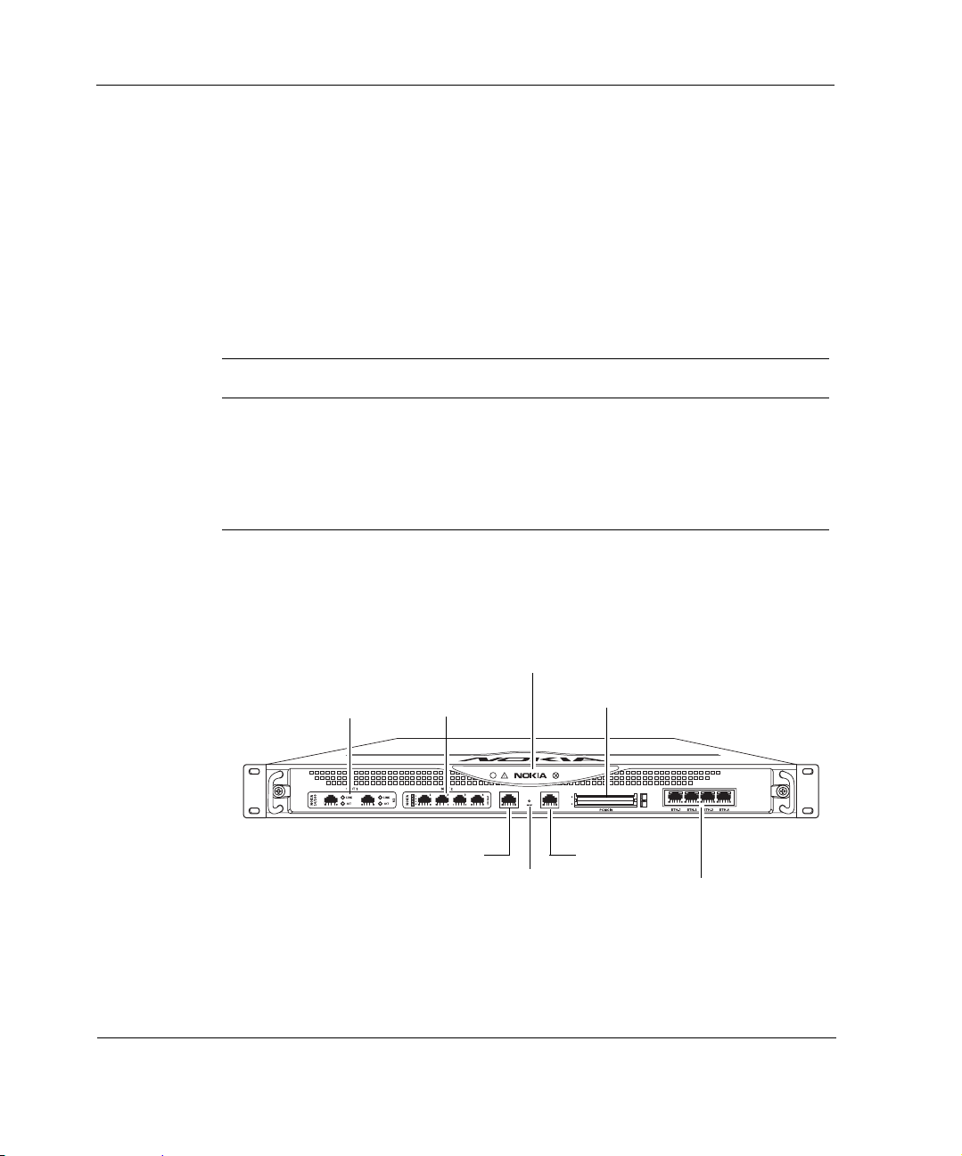
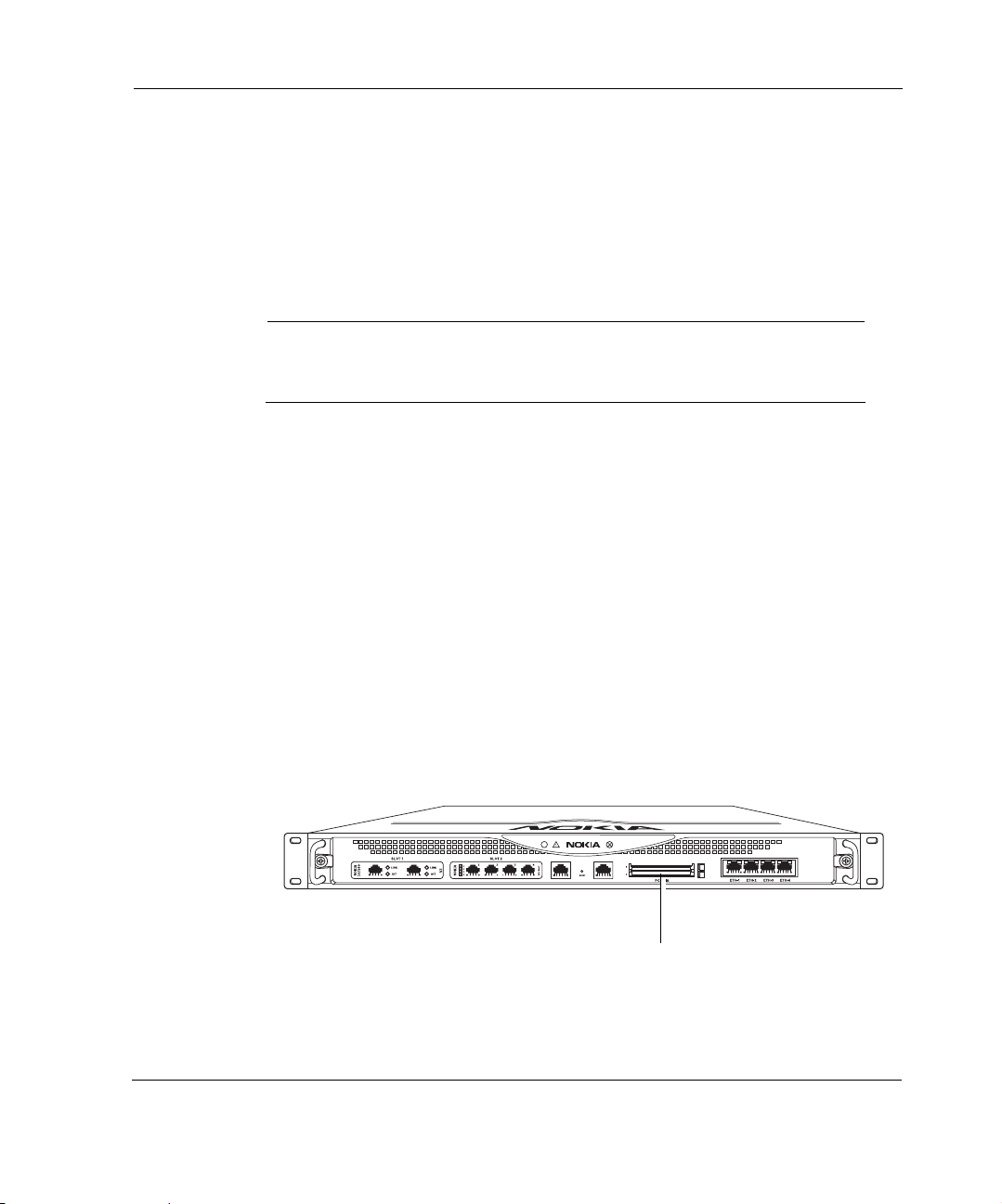
The following figures show component locations for the Nokia
appliance.
Figure 1 Component Locations Front View
System status LEDs
PMC NIC slots (slots 1 and 2)
unpopulated in base bundle
PC-card slots
IP390
00525
Console port
Reset button
20 IP390, 105i & 105s Security Platform Installation Guide
AUX port
Four-port Gigabit Ethernet
Page 21
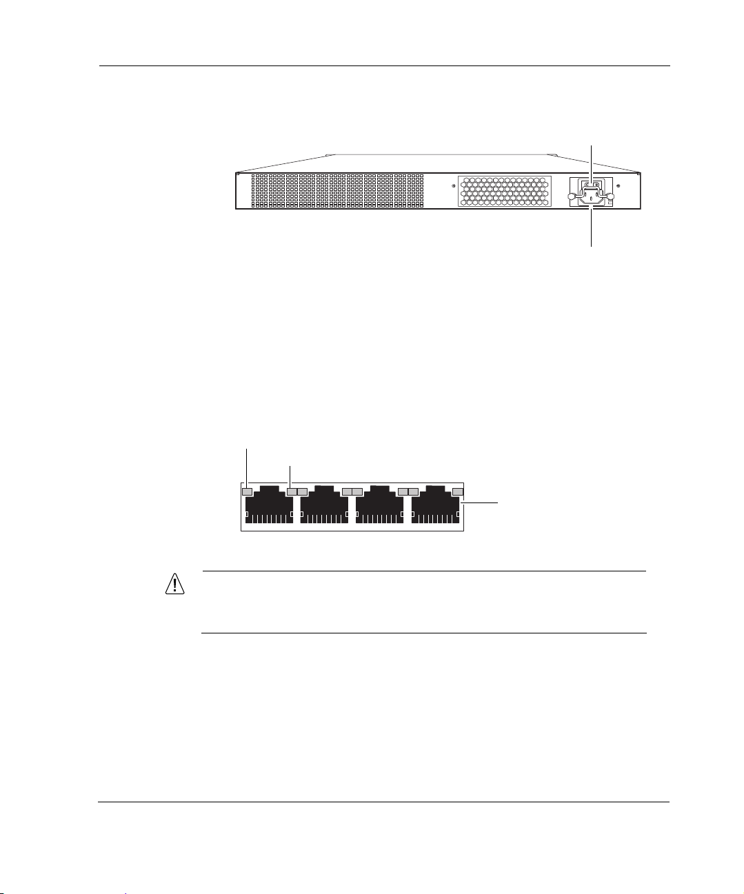
Figure 2 Component Locations Rear View
Built-In Gigabit Ethernet Ports
The four built-in Gigabit Ethernet ports are located on the front of the
appliance. Figure 3 shows the layout of the built-in Gigabit Ethernet ports and
status LEDs.
Figure 3 Built-In Gigabit Ethernet Ports Details
Activity LED (blinking yellow)
Link LED (solid yellow for 10/100 Mbps, solid green for 1000 Mbps)
About the Nokia IP390 Appliance
Power switch
00527
Power socket
RJ-45 connectors
00547
Caution
Cables that connect to the Gigabit Ethernet ports must be IEEE
802.3 compliant to prevent potential data loss.
IP390, 105i & 105s Security Platform Installation Guide 21
Page 22

1 Overview
Note
Nokia recommends the use of shielded twisted-pair cables and
connectors for best Electromagnetic Interference and Immunity
performance.
PMC Expansion Slots
The IP390 appliance provides two additional PMC network interface card
(NIC) slots, as described in Table 4.
Table 4 PMC Network Interface Card Slots
Interface For details, see...
Four-port copper 10/100
Ethernet
Two-port copper Gigabit
Ethernet (10/100/1000 Mbps)
Two-port fiber- optic Gigabit
Ethernet
“Four-Port 10/100 Mbps Ethernet NICs” on
page 61
“Two-Port Copper Gigabit Ethernet Network
Interface Card” on page 65
“Two-Port Fiber-Optic Gigabit Ethernet Network
Interface Card” on page 68
Note
Nokia products only support NICs purchased from Nokia or
Nokia-approved resellers. The Nokia Global Support Services group can
provide support only for Nokia products that use Nokia-approved
accessories. For sales or reseller information, contact a Nokia service
provider listed in the “Nokia Contact Information” on page 3.
22 IP390, 105i & 105s Security Platform Installation Guide
Page 23
System Status LEDs
You can monitor the basic operation of the appliance and NICs by
checking their status LEDs. The system status LEDs are located on the front
panel of the appliance, as Figure 4 shows.
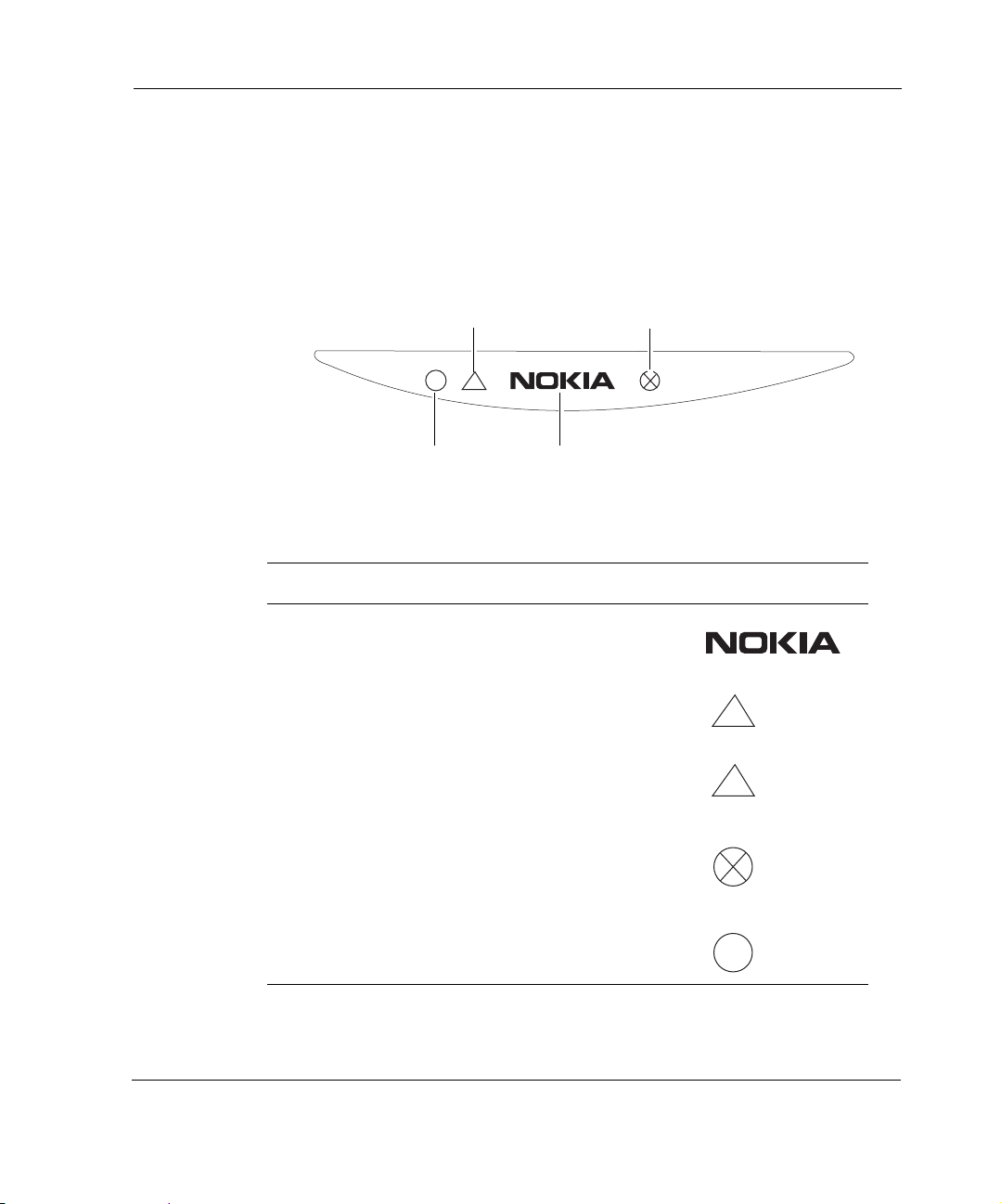
Figure 4 Appliance Status LEDs
About the Nokia IP390 Appliance
System OK (green)
Warning (yellow)
!
Power indicator (blue)
Fault (red)
Table 5 shows the system status LEDs and describes their meaning.
Table 5 System Status LEDs
Status Indicator Meaning Symbol
Solid blue Power on
Solid yellow Appliance is experiencing an
internal voltage problem.
Blinking yellow Appliance is experiencing a
temperature problem.
Solid red One or more fans are not
operating properly.
Power supply over temperature
fault.
!
!
00526
Blinking green System activity indicator
IP390, 105i & 105s Security Platform Installation Guide 23
Page 24

1 Overview
The location and meaning of the status LEDs for NICs are described in
Chapter 5, “Connecting PMC Network Interface Cards.”
For information on the built-in Gigabit Ethernet interface LEDs, see
“Built-In Gigabit Ethernet Ports” on page 21.
For information on the four-port Ethernet NIC LEDs, see “Four-Port 10/
100 Mbps Ethernet NICs” on page 61.
Managing the IP390 Appliance
You can manage the appliance by using one of the following interfaces:
Nokia Network Vo yager—an SSL-secured, Web-based element
management interface to Nokia IP appliances. Network Voyager is
preinstalled on the
operating system. With Network Voyager, you can manage, monitor, and
configure the IP390 appliance from any authorized location within the
network by using a standard Web browser.
For information about how to access Network Voyager and the related
reference materials, see “Using Nokia Network Voyager” on page 45.
appliance and enabled through the IPSO
The IPSO command-line interface (CLI)—an SSHv2-secured interface
that enables you to easily configure Nokia IP appliances from the
command line. Everything that you can accomplish with Network
Voyager—manage, monitor, and con figure the IP390 appliance—you can
also accomplish with the CLI.
For information about how to access the CLI, see the CLI Reference
Guide for the version of Nokia IPSO you are using.
Nokia Horizon Manager—a secure GUI-based software image
management application. With Horizon Manager , you can securely install
and upgrade the Nokia IPSO operating system, plus hardware and thirdparty applications such as Check Point VPN-1. Horizon Manager can
perform installations and upgrades on up to 2,500 Nokia IP appliances,
offering administrators the most rapid and dependable method to perform
Check Point application upgrades.
24 IP390, 105i & 105s Security Platform Installation Guide
Page 25
Logging Options
The IP390 supports two options for storing local system log files, as described
in the following topics:
Using Hard-Disk Drives for Logging
Using a Flash-Memory PC Card for Logging
Note
You can use only one device for logging (whether it’s a hard-disk drive or
flash-memory PC card) at a time.
Using Hard-Disk Drives for Logging
The appliance supports a single hard-disk drive, which provides 40 GB
of disk storage. You can use the hard-disk drive for storing log files.
Logging Options
Using a Flash-Memory PC Card for Logging
The appliance has two PC-card slots, both of which support 1-GB flash memory
PC cards. The slots are labeled PCMCIA and are located on the front of the
appliance, as Figure 5 shows. The
flash-memory PC card at a time.
Figure 5 Location of the PCMCIA Card Slot
IP390, 105i & 105s Security Platform Installation Guide 25
appliance supports using only one
IP390
00525
PCMCIA card slots
Page 26
1 Overview
You can use the flash-memory PC card to store local system logs.
Nokia supports only flash-memory PC cards purchased from Nokia or
Nokia-approved resellers. For more information, contact the appropriate
Nokia customer support site listed in “Nokia Contact Information” on page 3.
Site Requirements, Warnings, and Cautions
Before you install a Nokia appliance, ensure that your computer room
or wiring closet conforms to the environmental specifications listed in
Chapter A, “Technical Specifications.”
Warning
Excessive electromagnetic interference (EMI) can occur if you use
controls, make performance adjustments, or follow procedures that are
not described in this document.
Warning
To reduce the risk of fire, electric shock, and injury when you use
telephone equipment, follow basic safety precautions. Do not use the
product near water.
Caution
Replace the battery only with the same or equivalent type battery
recommended by the manufacturer. Dispose of used batteries
according to the manufacturer's instructions.
Caution
Do not block any of the ventilation holes on the appliance. The
components might overheat and become damaged.
26 IP390, 105i & 105s Security Platform Installation Guide
Page 27
Warning
Hazardous radiation exposure can occur if you use controls, make
performance adjustments, or follow procedures that are not described in
this document.
Caution
For IP390 appliances intended for shipment outside of the United
States, the cord might be optional. If a cord is not provided, use a
power cord rated at 6A, 250V, maximum 15 feet long, made of HAR
cordage and IEC fittings approved by the country of end use.
Software Requirements
The Nokia appliance supports the following operating system and
applications:
Nokia operating system software requirements—IPSO v4.1 or later
Check Point VPN-1 versions compatible with the version of Nokia IPSO
you are using
Software Requirements
For information about updates to the software requirements or additional
applications that have become available since this guide was published,
contact your Nokia service provider, as listed in “Nokia Contact Information”
on page 3.
Product Disposal
At the end of its useful life, your appliance and all peripherals included with
it, including power cords and cables, must be disposed of in accordance with
all applicable national, state, and local laws and regulations. These devices
contain materials and components that must be disposed of properly.
IP390, 105i & 105s Security Platform Installation Guide 27
Page 28
1 Overview
Therefore, to help prevent damage to the environment, Nokia encourages you
to dispose of these devices in an environmentally-friendly manner.
The following resources are available to you to help with equipment-disposal
decisions:
Many Nokia products are labeled with information about the materials
used in their manufacture that can help those who will process equipment
after you have disposed of it.
The Nokia web site (http://www.nokia.com) provides information about
our environmental programs and practices, which includes details about
materials used in manufacturing and end-of-life practices. You can also
find your product’ s Eco Declaration, which provi des basic information on
the environmental attributes of the product covering material use,
packaging, disassembly, and recycling.
Contact your local waste management agencies for guidelines specific to
your area.
The crossed-out wheeled bin means that within the European Union the product
must be taken to separate collection at the product end-of-life. This applies to your
device but also to any enhancements marked with this symbol. Do not dispose of
these products as unsorted municipal waste.
28 IP390, 105i & 105s Security Platform Installation Guide
Page 29

2 Installing the Nokia IP390, 105i &
105s Appliance
This chapter describes how to install the Nokia appliance. The
following topics are covered:
Before You Begin
Rack Mounting the Appliance
Connecting Power
Connecting to the Console or Auxiliary Port
Connecting to Network Interfaces
Before You Begin
To rack-mount the appliance, you need:
Phillips-head screwdriver
Grounding wrist strap
Suitable, grounded work surface on which to place the chassis tray
assembly
IP390, 105i & 105s Security Platform Installation Guide 29
Page 30
2 Installing the Nokia IP390 Appliance
Caution
To help guard against electrostatic discharge damage, make sure
you are properly grounded by using a grounding wrist strap and
following the instructions provided with the wrist strap before you
handle the components or open the appliance.
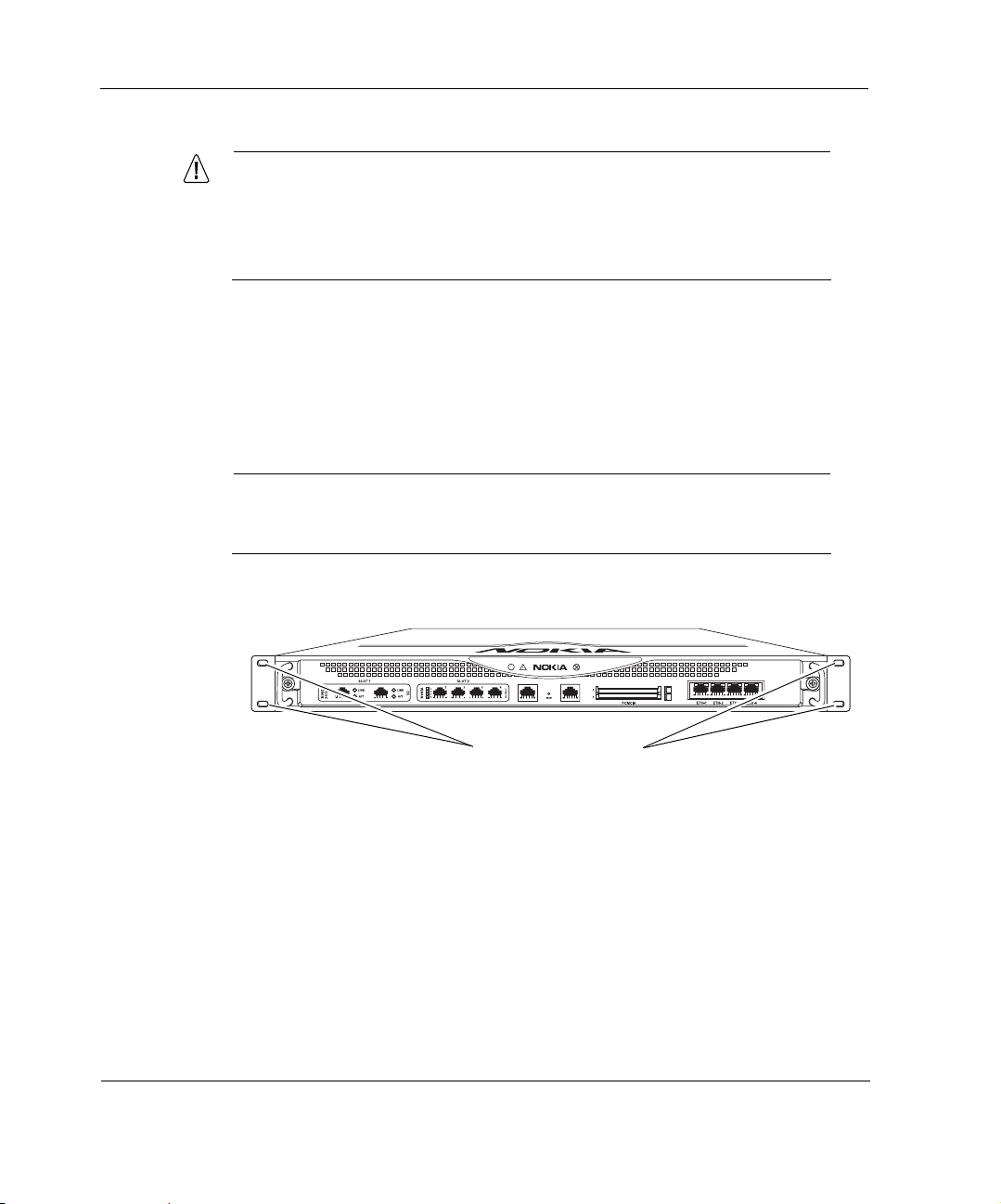
Rack Mounting the Appliance
The appliance mounts in a standard 19-inch rack with four mounting
screws as Figure 6 shows.
Note
To avoid damaging your equipment, Nokia recommends that you use all
four rack-mounting screws when you install your appliance on the rack.
Figure 6 Mounting Screws Location
IP390
00525
Mounting screw slots
30 IP390, 105i & 105s Security Platform Installation Guide
Page 31

Connecting Power
Two mounting positions are available allowing you to mount the unit either
flush with the rack, or two inches forward of the rack.
Figure 7 Adjustable Mounting Brackets
Brackets located for
flush with rack
installation
Brackets located for
forward of rack
installation
Caution
Blocking ventilation openings during installation may result in
damage to the appliance.
Connecting Power
The power plug and power switch for the appiance is located on the
back of the appliance, as Figure 8 shows.
IP390
IP390
00539
IP390, 105i & 105s Security Platform Installation Guide 31
Page 32

2 Installing the Nokia IP390 Appliance
Note
The IP390 appliance power supply automatically detects the input voltage
(1 15VAC/60Hz [90 to 132] or 220VAC/50Hz [180 to 264]) and configures
itself appropriately.
Figure 8 Back Panel Power Switch and Socket
To connect to the power supply
1. Connect the power cord securely into the power socket on the back of the
appliance.
2. Plug the other end of the cord into a three-wire grounded power strip or
wall outlet.
00527
Power socket
Connecting to the Console or Auxiliary Port
If you do not use DHCP to perform the initial configuration of your Nokia
IP390 appliance, you must use a serial console connection (RJ-45
null-modem cable included). For information about using DHCP for initial
configurations, see Chapter 3, “Performing the Initial Configuration.”
After you perform the initial configuration, you no longer need the console
connection.
You can use any standard VT100-compatible terminal with an RS-232 data
terminal equipment (DTE) interface or terminal-emulation program
If you connect the console port to a data communications equipment (DCE)
device, use a straight-through cable.
Use the following configuration settings for the console:
32 IP390, 105i & 105s Security Platform Installation Guide
Page 33

Connecting to the Console or Auxiliary Port
9600 bps
8 data bits
No parity
1 stop bit
To connect to the console with a null-modem cable
1. Connect the supplied null-modem console cable to the console port on the
front panel of the
appliance.
Use only the RJ-45 port labeled Console on the front panel; the serial
(AUX) port is an auxiliary modem port.
One RJ-45 termination has a retractable shroud that releases or secures
the RJ-45 tab. Use this end of the cable when connecting to the console
port of the IP390.
IP390
00525
Console port
For cable pin assignments for the console connection, see “Console Port”
on page 36.
2. Connect the other end of the cable to the VT100 console or to a system
running a terminal-emulation program.
The cable that Nokia provide
s with appliances includes a latching
mechanism used to secure the cable to the console port or auxiliary port of
your appliance.
IP390, 105i & 105s Security Platform Installation Guide 33
Page 34

2 Installing the Nokia IP390 Appliance
Note
To use the cable for modem connections from the auxiliary port, you need
to order a modem cable kit. For information about contacting Nokia to
order the kit, see “Nokia Contact Information” on page 3.
Note
The cable described in this section is a rollover cable, which is required
for IP390 console and auxiliary port connections. You cannot use
standard Ethernet cables for console and auxiliary connections.
To connect the cable, push the connector into the receptacle, as you would
with other similar cables. To disconnect the cable, push the cable toward the
34 IP390, 105i & 105s Security Platform Installation Guide
Page 35

Connecting to the Console or Auxiliary Port
appliance, pull back on the boot to release the latch, and pull the connector out
of the receptacle.
To connect the cable
1 + 2 =
2
Pull boot
1
Push cable
To disconnect the cable
00548a
You can connect the other end of the cable to a DB-9 console connection
(using the appliance console port and the DB-9 female adaptor) or to a DB-25
modem connection (using the appliance auxiliary port and the DB-25 male
IP390, 105i & 105s Security Platform Installation Guide 35
Page 36

2 Installing the Nokia Appliance
adaptor). The DB-9 adapter is provided with the cable. The DB-25 adaptor is
provided with Nokia modem cable kits for the
appliance.
00552
Console Port
Use the built-in console port, shown in Figure 6, to supply information that
makes the appliance available on the network at speeds up to 9600 bps. The
default configuration of the serial ports are: 9600 baud, 8 bits, no parity, and 1
stop. Table 6 provides pin assignment information for console connections. If
you need to access the devices locally , you must use the console port.
Table 6 Pin Assignments for Console Connector and Cable
Console Port
(DTE)
Signal RJ-45 Pin RJ-45 Pin DB-9 Pin Signal
RTS 1 8 8 CTS
DTR 2 7 6 DSR
TxD 3 6 2 RxD
DB-9 female adapter
RJ-45 to RJ-45 Rollover
Cable
DB-25 male adapter
RJ-45 to DB-9
Terminal
Adapter Console Device
GND 4 5 5 GND
36 IP390, 105i & 105s Security Platform Installation Guide
Page 37

Connecting to the Console or Auxiliary Port
RJ-45 to DB-9
Console Port
(DTE)
GND 5 4 5 GND
RxD 6 3 3 TxD
DSR 7 2 4 DTR
CTS 8 1 7 RTS
RJ-45 to RJ-45 Rollover
Cable
Terminal
Adapter Console Device
The console cable provided with the IP390 is comprised of two parts:
6-foot rollover cable with RJ-45 terminations
RJ-45 to DB-9 adapter
On the opposite end of the console cable, connect the RJ-45 to the DB-9
adapter, which you can then connect to the host terminal.
Auxiliary Port
Use the built-in serial (AUX) port, shown in Figure 1, to establish a modem
connection for managing the appliance remotely or out-of-band. The default
configuration of the serial ports are: 9600 baud, 8 bits, no parity, and 1 stop.
bit. Table 7 provides pin assignment information for modem connections.
Table 7 Pin Assignments for AUX Connector and Modem Cable
Auxiliary Port
(DTE)
Signal RJ-45 Pin RJ-45 Pin DB-25 Pin Signal
RTS 1 8 4 RTS
DTR 2 7 20 DTR
IP390, 105i & 105s Security Platform Installation Guide 37
RJ-45 to RJ-45 Rollover
Cable
RJ-45 to DB-25
Modem Adapter Modem
Page 38

2 Installing the Nokia IP390 Appliance
Auxiliary Port
(DTE)
TxD 3 6 3 TxD
GND 4 5 7 GND
GND 5 4 7 GND
RxD 6 3 2 RxD
DSR 7 2 8 DCD
CTS 8 1 5 CTS
RJ-45 to RJ-45 Rollover
Cable
RJ-45 to DB-25
Modem Adapter Modem
Connecting to Network Interfaces
Connect at least one network interface to use as the Network Voyager system
management interface. This interface is configured during the system startup
procedure, as described in Chapter 3, “Performing the Initial Configuration.”
You can also connect the remaining LAN interface cables at this point,
although you are not required to do so.
To connect Ethernet devices
Use a straight-through RJ-45 cable to connect to a 10-Mbps or 100-Mbps
hub.
Use a crossover RJ-45 cable to connect directly to a host.
For details, see “Ethernet NIC Connectors and Cables” on page 63.
To connect copper Gigabit Ethernet devices
Use a straight-through or crossover RJ-45 cable to connect to a 10-Mbps,
100-Mbps, or 1000-Mbps hub or directly to a host.
38 IP390, 105i & 105s Security Platform Installation Guide
Page 39

Connecting to Network Interfaces
Note
All Nokia copper Gigabit Ethernet NICs support cable auto-sensing.
You can use a straight-through or crossover cable to connect the NIC
to a Gigabit Ethernet hub or switch, or to connect directly to a host.
For details, see “Copper Gigabit Ethernet Connectors and Cables” on page 66.
To connect fiber-optic Gigabit Ethernet devices
Use a multimode, fiber-optic cable with an LC connector to connect to a
10-Mbps, 100-Mbps, or 1000-Mbps hub or directly to a host. The
destination end of the cable can be either LC or SC, depending on the type
of connector required for the destination Gigabit Ethernet device. You can
also use a half-duplex LC-to-LC cable to loop back the transmit port of an
interface to the receiver port.
For details, see “Fiber-Optic Gigabit Ethernet Connectors and Cables” on
page 69.
After you connect the network interfaces, continue with Chapter 3,
“Performing the Initial Configuration.”
IP390, 105i & 105s Security Platform Installation Guide 39
Page 40

2 Installing the Nokia IP390 Appliance
40 IP390, 105i & 105s Security Platform Installation Guide
Page 41

3 Performing the Initial
Configuration
The first time you turn power on to a Nokia appliance, the initial
configuration process begins. This process enables you to configure the
network settings and provides access to the admin account.
You can perform the initial configuration in two ways.
You can configure a DHCP server to provide the initial configuration
information the first time the appliance is started.
You can perform the initial configuration manually by using a console
connection.
This chapter describes how to perform the initial configuration manually by
using a console connection. It includes the following sections:
Using a Console Connection
Using Nokia Network Voyager
Using the Command-Line Interface
Using Nokia Horizon Manager
For information about how to use the DHCP client for initial configuration,
see the Read Me First document.
IP390, 105i & 105s Security Platform Installation Guide 41
Page 42

3 Performing the Initial Configuration
Using a Console Connection
If you have not already done so, you need to connect to the console port to
complete the initial configuration. For information about console connections,
see “Connecting to the Console or Auxiliary Port” on page 32.
Before you perform the initial configuration, you might gather the following
information, which can be useful during the configuration process:
What is the hostname?
What is the admin password?
Will you use Nokia Network Voyager for subsequent configuration?
Which interface will you use?
What is the assigned IP address and masklength?
What is the default router?
What is the interface speed?
Note
The default interface speed for the appliance is 1000 Mb ps.
You can make VLAN, SNMP community string, and remote logging
configuration choices at this time, although you can change them later.
To perform the initial configuration
1. Press the power switch to the “on” position to turn on power to the
appliance.
Power switchCooling fans
00527
42 IP390, 105i & 105s Security Platform Installation Guide
Page 43

Using a Console Connection
The fans on the back of the appliance turn on when you press the power
switch. Verify that the fans are running after you press the switch.
Check the power LED on the front panel of the appliance (the Nokia logo)
to ensure that the power supply is operating correctly. The power LED
should be illuminated. For more information about the system status
LEDs, see “System Status LEDs” on page 23.
If the power supply fans are not running, or if the power LED is not
illuminated:
Check the power supply cord to make sure it is properly connected.
Make sure the power switch is on.
Make sure the chassis tray assembly is pushed all the way in from the
front of the appliance and that the front panel retaining screws are
tightened.
Make sure that power is turned on to the power strip or wall receptacle
you plugged the appliance in to.
If the fans are still not running, or if the power LED does not illuminate,
contact your Nokia service provider as listed in “Nokia Contact
Information” on page 3 for technical support.
2. At the console a series of startup messages appears, then the console
prompt appears.
The prompt remains on the screen for about five seconds. If you type any
character during this time, the appliance activates the Nokia IPSO boot
manager.
BOOTMGR[0]>
Note
For information about using the boot manager, see the Nokia IPSO
Boot Manager Reference Guide.
After some miscellaneous output, the following prompt appears:
Hostname?
IP390, 105i & 105s Security Platform Installation Guide 43
Page 44

3 Performing the Initial Configuration
If the Hostname? prompt does not appear on the console, check the
console port and console display connections to ensure that the serial
cable is completely plugged in at both ends. If you verify the console
connections and still do not see either the BOOTMGR> or Hostname?
prompts, verify that the terminal or terminal emulator program settings
are correct. If the settings are correct, contact your Nokia service provider
as listed in “Nokia Contact Information” on page 3.
3. Respond to the Hostname? prompt within 30 seconds to prevent the
DHCP client from starting.
If the DHCP client starts, it might configure the appliance with an
incorrect host name and IP address (this could happen if a DHCP server
on your network is configured to respond to any request). To reset the
incorrect host name and IP address:
a. Establish a console connection to the appliance.
b. Enter the following:
rm /config/active
or
mv /config/active /config/active.old
c. Reboot the appliance.
d. Respond to the Hostname? prompt within 30 seconds to prevent the
DHCP client from restarting.
4. At each subsequent prompt, type the requested configuration information
and then press Enter.
For more information about how to respond to the prompts during the
initial configuration process, see the Getting Started Guide and Release
Notes for the version of Nokia IPSO you are using.
5. After you complete the initial configuration, you can use Network
Voyager to configure the remaining network ports.
44 IP390, 105i & 105s Security Platform Installation Guide
Page 45

Using Nokia Network Voyager
Use Nokia Network Voyager to configure and monitor your appliance. For
additional information about how to use Network Voyager, see “Viewing
Nokia IPSO Documentation by Using Nokia Network Voyager” later in this
section.
To open Nokia Network Voyager
1. Open a Web browser on the host you plan to use to configure or monitor
your appliance.
2. In the Location or Address field, enter the IP address of the initial
interface you configured for the appliance.
You are prompted to enter the admin username and the password you
entered when you performed the initial configuration.
Note
If the username login screen does not open, you might not have a
physical network connection between the host and yo ur appliance, o r
you might have a network routing problem. Confirm the information
you entered during the initial configuration and check that all cables
are firmly connected. For more information, see the troubleshooting
section in the installation guide for your appliance.
Using Nokia Network Voyager
IP390, 105i & 105s Security Platform Installation Guide 45
Page 46

3 Performing the Initial Configuration
Viewing Nokia IPSO Documentation by Using Nokia Network Voyager
Note
If you do not see the documentation as shown in Figure 9, you might
need to enable the document package. You do this be navigating to
Configuration > System Configuration > Packages > Manage Packages
and turning the package on.
The following documentation is available in Nokia Network Voyager and is
accessible from the Network Voyager interface, as shown in Figure 9:
Nokia Network Vo yager Reference Guide—This guide is the
comprehensive reference source for Nokia Network Voyager. To access
this source, look at the list in the navigation tree on the left side of the
window (as shown in Figure 9).You can also access the Nokia Network
Voyager Reference Guide and other Nokia IPSO documentation at the
Nokia support site (https://support.nokia.com) or on the software CD that
was delivered with your appliance.
Nokia Network Voyager Inline Help—You can access inline help when
you use Nokia
information source for
window you are viewing, click Help. A Close button is available at the
bottom of each inline help window you view.
Network Voyager. Inline help is the context-sensitive
Network Voyager. To access inline help for the
46 IP390, 105i & 105s Security Platform Installation Guide
Page 47

Using the Command-Line Interface
Figure 9 Nokia Network Voyager Reference Access Points
Link to complete user
documentation
Link to inline help (context sensitive help)
Using the Command-Line Interface
You can also use the Nokia IPSO command-line interface (CLI) to manage
and configure Nokia IP appliances from the command line. Everything that
you can accomplish with Network Voyager you can also do with the CLI.
IP390, 105i & 105s Security Platform Installation Guide 47
Page 48

3 Performing the Initial Configuration
To access the command-line interface
1. Log on to the appliance by using a command-line connection (SSH,
console, or Telnet) over a TCP/IP network as an admin, cadmin, or
monitor user:
If you log in as a cadmin (cluster administrator) user, you can change
and view configuration settings on all the cluster nodes. For
information about how to administer a cluster, see the traffic
management commands section in the CLI Reference Guide for the
version of Nokia IPSO you are using.
2. If you log in as a monitor user, you can execute only the show form of
commands. That is, you can view configuration settings, but you cannot
change them.
You can now execute CLI commands from the CLI shell and the Nokia IPSO
shell. The Nokia IPSO shell is what you see when you initially log on to the
appliance.
Execute from To Implement Purpose
Nokia IPSO
command line
Nokia IPSO
command line
Command files From inside the CLI shell, enter
48 IP390, 105i & 105s Security Platform Installation Guide
Enter the following command
to invoke the CLI shell:
clish
The prompt changes, and you
can then enter CLI commands.
Enter
clish -c
“cli-command”
load commands
filename
Enter any CLI commands in an
interactive mode with help text
and other helpful CLI features.
Execute a single CLI
command. You must place
double-quotation marks
around the CLI command.
Load commands from a text
file that contains commands.
The argument must be the
name of a regular file.
Page 49

For more information about how to access and use the CLI, see the Nokia CLI
Reference Guide for the version of Nokia IPSO you are using.
Using Nokia Horizon Manager
Nokia Horizon Manager is an extension of the Network Voyager management
functionality.
While Network Voyager provides the device administrator access to network
configuration tasks (such as interface configuration and routing configuration)
and security configuration tasks (such as user configuration and access
configuration), Horizon Manager concentrates on secure software image,
inventory, and management of Nokia IP appliances.
Using Horizon Manager, an administrator can obtain configuration
information, upgrade (or downgrade) the operating system, perform
application installations, and distribute necessary licensing to multiple
appliances simultaneously, thereby reducing potential human error and
improving productivity.
Using Horizon Manager, a network security professional can manage multiple
devices simultaneously, perform parallel software upgrades, device
verifications, device configuration, file backups, and more.
Using Nokia Horizon Manager
Horizon Manager is designed to manage and configure a large number of
Nokia security appliances that reside on a corporate enterprise, managed
service provider (MSP), or hosted applications service provider network
(ASP).
For information about how to obtain Horizon Manager or to learn more about
the Horizon Manager, see “Nokia Contact Information” on page 3.
060228
IP390, 105i & 105s Security Platform Installation Guide 49
Page 50

3 Performing the Initial Configuration
50 IP390, 105i & 105s Security Platform Installation Guide
Page 51

4 Installing and Replacing
Network Interface Cards
Your appliance comes with any network interface cards (NICs) you
ordered already installed. This chapter describes how to remove, add, or
replace NICs later if it becomes necessary.
The following topics are covered:
Deactivating Configured Interfaces
Removing, Installing, and Replacing NICs
Configuring and Activating Interfaces
Monitoring Network Interface Cards
For detailed information on specific NICs, see Chapter 5, “Connecting PMC
Network Interface Cards.”
Caution
You should have a working knowledge of networking equipment
before attempting to service an IP390 appliance. Limit service of the
unit to the procedures described in this chapter.
IP390, 105i & 105s Security Platform Installation Guide 51
Page 52

4 Installing and Replacing Network Interface Cards
Caution
Protect your
electrostatic discharge (ESD) by making sure you are pr operly
grounded before touching any electronic components.
appliance and other electronic equipment from
Deactivating Configured Interfaces
If you are removing or replacing an installed NIC, use Network Voyager to
deactivate any configured ports on the NIC before removing it.
Deactivate all of the logical interfaces on the NIC.
Deactivate all of the physical interfaces on the NIC.
If you do not deactivate the interfaces before removing the NIC, you may
have to reinstall the NIC to deactivate its logical and physical interfaces in
Network Voyager.
For information about how to access Network Voyager, see “Using Nokia
Network Voyager” on page 45.
Removing, Installing, and Replacing NICs
Note
Before removing a configured NIC with these instructions, you must
deactivate the NIC in Network Voyager. For additional information, see
“Deactivating Configured Interfaces” on page 52.
Use these instructions to remove, install, or replace a NIC in the IP390
appliance. Some steps are not applicable to all procedures. The instructions
point out steps appropriate to each procedure.
52 IP390, 105i & 105s Security Platform Installation Guide
Page 53

Before You Start
To remove, install, or replace a Nokia NIC, you need the following:
A Phillips-head screwdriver
Physical access to the appliance
Access to the appliance by using Nokia Network Voyager or the CLI
Suitable, grounded work surface
Network interface card kit
To remove, install, or replace a NIC
Note
Because power to the appliance is automatically disconnected
when the chassis tray assembly is opened, you do not need to
manually disconnect the power for this procedure. Any servicing of
the unit, however, should be completed with the chassis tray
assembly fully removed from the appliance. Power is still active in the
chassis body and care should be taken when working on the power
supply or power supply wiring without disconnecting the power cord.
Removing, Installing, and Replacing NICs
1. Use Network Voyager or the CLI to halt the appliance.
To use Network Voyager to shut the appliance down, select
System > Configuration > Reboot or Shutdown > Halt.
To use the CLI to shut the appliance down, enter halt at the prompt.
IP390, 105i & 105s Security Platform Installation Guide 53
Page 54

4 Installing and Replacing Network Interface Cards
2. Use your fingers or a screwdriver to loosen the retaining screws that hold
the chassis tray assembly.
Chassis tray assembly retaining screws
3. Gently pull the chassis tray assembly forward to expose the NIC
connectors. Remove the tray completely to avoid damaging components.
IP390
00525
IP390
00537
54 IP390, 105i & 105s Security Platform Installation Guide
Page 55

Removing, Installing, and Replacing NICs
4. From underneath the chassis tray assembly, remove the bezel retaining
screws.
00529
If you are installing a NIC in an unoccupied slot, remove the blank bezel
that occupies the space in the appliance front panel, retain it for future
use, and proceed to step 7.
5. From above the chassis tray assembly, remove the NIC retaining screws
from the back of the NIC.
00530
IP390, 105i & 105s Security Platform Installation Guide 55
Page 56

4 Installing and Replacing Network Interface Cards
6. Remove the NIC by lifting the back of the NIC away from the chassis tray
assembly and pulling the NIC gently away from the front panel.
7. Insert the new NIC or blank bezel.
If you are removing a NIC without installing another NIC:
a. Insert a blank bezel into the front panel slot formerly occupied by the
NIC and push it gently into place.
00533
Make sure that the bezel is completely seated into the front panel and
that the screw holes on the bottom of the bezel align with those in the
front panel.
Note
To reduce electromagnetic interference (EMI), a blank bezel needs to
be installed in the place of any NIC you have removed.
b. Proceed to step 9.
56 IP390, 105i & 105s Security Platform Installation Guide
Page 57

Removing, Installing, and Replacing NICs
If you are installing or replacing a NIC, insert the NIC.
a. Insert the NIC bezel into the front panel.
00532
b. Gently push the back of the NIC down toward the chassis tray
assembly.
Make sure that the NIC edge is completely seated into the connectors
on the chassis tray assembly.
8. From the top of the chassis tray assembly, screw the NIC retaining screws
into the standoffs on the back of the NIC.
00531
IP390, 105i & 105s Security Platform Installation Guide 57
Page 58

4 Installing and Replacing Network Interface Cards
9. From beneath the chassis tray assembly, screw in the bezel retaining
screws.
10. Slide the chassis tray assembly back into the appliance until it clicks into
place.
00528
IP390
00538
The appliance automatically restarts when the chassis tray assembly
clicks into place.
58 IP390, 105i & 105s Security Platform Installation Guide
Page 59

Configuring and Activating Interfaces
11. Tighten the retaining screws that hold the chassis tray assembly.
Chassis tray assembly retaining screws
Configuring and Activating Interfaces
The appliance automatically detects any new NIC when the appliance
is restarted. Use Network Voyager to configure and activate the logical and
physical interfaces on the NIC.
For information about how to access Network Voyager and the related
reference materials, see “Using Nokia Network Voyager” on page 45.
IP390
00525
Monitoring Network Interface Cards
You can asses the general operating condition of the NICs in your appliance
by looking at the LED status indicators on the NICs. The status indicators for
each NIC are explained in the NIC reference chapter.
For status indicator information for the built-in Gigabit Ethernet ports, see
“Built-In Gigabit Ethernet Ports” on page 21.
For status indicator information for the four-port Ethernet NIC, see “Four-
Port 10/100 Mbps Ethernet NICs” on page 61.
For status indicator information for the two-port copper Gigabit Ethernet NIC,
see “Two-Port Copper Gigabit Ethernet Network Interface Card” on page 65.
IP390, 105i & 105s Security Platform Installation Guide 59
Page 60

4 Installing and Replacing Network Interface Cards
For status indicator information for the two-port fiber-optic Gigabit Ethernet
NIC, see “Two-Port Fiber -Optic Gigabit Ethernet Network Interface Card” on
page 68.
Use Network Voyager to access detailed port information. For information
about accessing Network Voyager, see “Using Nokia Network Voyager” on
page 45. Y ou can also use the Nokia IPSO tcpdump command to examine the
track on a specific port.
60 IP390, 105i & 105s Security Platform Installation Guide
Page 61

5 Connecting PMC Network
Interface Cards
This chapter describes the PMC network interface cards (NICs) available for
the IP390 appliance and describes how to connect those NICs to your
network. The following NICs are covered:
Four-Port 10/100 Mbps Ethernet NICs
Two-Port Copper Gigabit Ethernet Network Interface Card
Two-Port Fiber-Optic Gigabit Ethernet Network Interface Card
For instructions on adding or replacing interface cards, see Chapter 4,
“Installing and Replacing Network Interface Cards.”
Caution
Protect your
electrostatic discharge (ESD) damage by making sure you are
properly grounded before you touch any electronic component.
appliance and other electronic equipment from
Four-Port 10/100 Mbps Ethernet NICs
The IP390 appliance supports Nokia-approved, four-port UTP5 dual-mode
10-Mbps and 100-Mbps Ethernet NICs.
IP390, 105i & 105s Security Platform Installation Guide 61
Page 62

5 Connecting PMC Network Interface Cards
When you purchase an Ethernet NIC with your appliance, the NIC is
installed before the appliance is delivered to you. For information on how to
add or replace a NIC later, see Chapter 4, “Installing and Replacing Network
Interface Cards.”
Ethernet NIC Features
The Ethernet PMC NIC supports the following features:
Supports traffic at 10 and 100 Mbps
Packet tracing for analysis through tcpdump
Compliance with IEEE 802.3 Ethernet specification
You can configure and monitor Ethernet interfaces with Network Voyager.
Specifically, you set the port speed and full-duplex or half-duplex mode by
using Network Voyager.
Figure 10 Four-Port Ethernet NIC Front Panel Details
Ports
1
2
3
4
Link LEDs (solid green)
Activity LEDs (blinking green)
321
4
10/100 BaseT
00026.2
After the power is turned on, the Ethernet link LEDs on the appliance and on
the remote equipment illuminate to indicate the connection. As data is
transmitted, the activity LEDs on the appliance light up.
62 IP390, 105i & 105s Security Platform Installation Guide
Page 63

Four-Port 10/100 Mbps Ethernet NICs
Ethernet NIC Connectors and Cables
The connectors on the Ethernet NIC are RJ-45 connectors:
To connect to a 10-Mbps or 100-Mbps hub, use a straight-through RJ-45
cable.
To connect directly to a host, use an RJ-45 crossover cable.
Use IEEE 802.3 10BASE-T, 100BASE-TX unshielded twisted-pair,
full-duplex or half-duplex cable.
Caution
Cables that connect to the Ethernet card must be IEEE 802.3
compliant to prevent potential data loss.
You can order appropriate adapter cables separately. You can order additional
cables from a cable vendor of your choice.
Figure 11 shows the pin assignments for the cable. The RJ-45 cable output
connector is numbered from right to left, with the copper tabs facing up and
toward you.
IP390, 105i & 105s Security Platform Installation Guide 63
Page 64

5 Connecting PMC Network Interface Cards
Figure 11 Outpu t Connector for the Ethernet Cable
81
Pin# Assignment
1TX
2TX
00270
3RX
4
5
6RX
7
8
Figure 12 shows the pin assignments for the RJ-45 cross-over cable.
Figure 12 Ethernet Crossover-Cable Pin Connections
1
2
3
4
5
6
7
8
1
2
3
4
5
6
7
8
00017.1
You can also use cables intended for Gigabit Ethernet NIC connections for
your Ethernet NIC connections, as shown in Figure 13.
64 IP390, 105i & 105s Security Platform Installation Guide
Page 65

Two-Port Copper Gigabit Ethernet Network Interface Card
Figure 13 Gigabit Ethernet Crossover Cable Pin Connections
1
2
3
4
5
6
7
8
1
2
3
4
5
6
7
8
00020
Two-Port Copper Gigabit Ethernet Network
Interface Card
All NICs installed in an appliance are installed into slots on the appliance.
Ethernet NICs can occupy any of the slots or subslots in an appliance that
other I/O cards do not occupy.
Note
Copper Gigabit Ethernet NICs you use in appliance s need to be the
Version 2 type, as indicated on the right end of the NIC faceplate. These
NICs are sold by Nokia under the order code NIF4425.
Copper Gigabit Ethernet NIC Features
The copper Gigabit Ethernet NIC supports the following features:
Supports traffic at 10, 100, and 1000 Mbps
High bandwidth
Half-duplex mode operation up to 100 Mbps
IP390, 105i & 105s Security Platform Installation Guide 65
Page 66

5 Connecting PMC Network Interface Cards
Packet tracing for analysis through tcpdump
Compliance with IEEE 802.3ab Gigabit Ethernet specification
Figure 14 shows the front panel details for the two-port copper Gigabit
Ethernet NIC you use in the Nokia IP390 appliance.
Figure 14 Two-Port Copper Gigabit Ethernet NIC
Link LED (solid yellow for 10/100 Mbps, solid green for 1000 Mbps)
Activity LEDs (blinking yellow)
1000BaseT
LINK
ACT
RJ-45 connectors
LINK
ACT
V2
00386.5
Copper Gigabit Ethernet Connectors and Cables
The copper Gigabit Ethernet NIC receptacles use RJ-45 connectors.
To connect to a 1 Gbps hub, switch, or router, use a straight-through RJ-45
cable (Cat 5 type cable, or as required by your network configuration).
Note
All Nokia copper Gigabit Ethernet NICs support cable auto-sensing. You
can use a straight-through or crossover cable to connect the NIC to a
Gigabit Ethernet hub or switch, or to connect directly to a host.
In Figure 15, the RJ-45 cable output connector is numbered from ri ght to left,
with the copper pins facing up and toward you.
66 IP390, 105i & 105s Security Platform Installation Guide
Page 67

Two-Port Copper Gigabit Ethernet Network Interface Card
Figure 15 Copper Gigabit Ethernet Cable Connector Output Pin
Assignments
81
Gigabit
Pin#
Ethernet
Assignment
10/100 Mbps
Assignment
00270
1BI_DA+ TX
2BI_DA- TX
3BI_DB+ RX
4
5
6BI_DB- RX
7 BI_DD+
8 BI_DD-
BI_DC+
BI_DC-
T o connect directly to a host, use an RJ-45 crossover cable wired as Figure 16
shows.
Figure 16 Gigabit Ethernet Crossover Cable Pin Connections
1
2
3
4
5
6
7
8
1
2
3
4
5
6
7
8
00020
IP390, 105i & 105s Security Platform Installation Guide 67
Page 68

5 Connecting PMC Network Interface Cards
To connect the appliance to other network components, you can order
appropriate adapter cables separately from a cable vendor of your choice.
Two-Port Fiber-Optic Gigabit Ethernet Network Interface Card
All NICs installed in an appliance is installed into slots on the appliance.
Ethernet NICs can occupy any of the slots or subslots in an appliance that
other I/O cards do not occupy.
Fiber-Optic Gigabit Ethernet NIC Features
The two-port fiber-optic Gigabit Ethernet NIC provides the following
features:
Supports traffic at 1000 Mbps
High bandwidth
Full-duplex mode operation up to 1 Gbps (no half-duplex support)
Link speed auto advertising
Packet tracing for analysis through tcpdump
Compliance with IEEE 802.3z Gigabit Ethernet specification
You can configure and monitor Ethernet interfaces with Nokia Network
Voyager, the Web-based element management interface to Nokia IP
appliances. Specifically, you set the port speed and full-duplex mode with
Network Voyager.
Figure 17 shows the front panel details for the two-port fiber-optic Gigabit
Ethernet NIC you use in the appliance.
68 IP390, 105i & 105s Security Platform Installation Guide
Page 69

Two-Port Fiber-Optic Gigabit Ethernet Network Interface Card
Figure 17 Two-Port Fiber-Optic Gigabit Ethernet NIC
Link LEDs (solid green)
Activity LEDs (blinking yellow)
GIGE
00206
Ports
Fiber-Optic Gigabit Ethernet Connectors and Cables
To connect the two-port Gigabit Ethernet NIC to other network components,
use a multimode, fiber-optic cable with an LC connector for each NIC
interface. The destination end of the cable can be either LC or SC, depending
on the type of connector required for the destination Gigabit Ethernet device.
You can also use a half-duplex LC-to-LC cable to loop back the transmit port
of an interface to the receiver port.
Two LC-to-SC cables are included with two-port fiber-optic Gigabit Ethernet
NICs. You can order additional cables from a cable vendor of your choice.
IP390, 105i & 105s Security Platform Installation Guide 69
Page 70

5 Connecting PMC Network Interface Cards
70 IP390, 105i & 105s Security Platform Installation Guide
Page 71

6 Installing and Replacing Other
Components
This chapter provides information on how to add or replace user serviceable
items other than network interface cards (NICs) in your
following topics are covered:
Replacing the Compact Flash Memory Card
Installing a Flash-Memory PC Card
Installing or Replacing a Hard-Disk Drive
Configuring a PC Card or Hard-Disk Drive for Logging
Replacing or Upgrading Memory
For instructions on adding or replacing interface cards, see Chapter 4,
“Installing and Replacing Network Interface Cards”.
appliance. The
Caution
You should have a working knowledge of networking equipment
before attempting to service an IP390 appliance. Limit service of the
appliance to the procedures described in this chapter.
IP390, 105i & 105s Security Platform Installation Guide 71
Page 72

6 Installing and Replacing Other Components
Caution
Protect your
electrostatic discharge (ESD) damage by making sure you are
properly grounded before you touch any component.
appliance and other electronic equipment from
Replacing the Compact Flash Memory Card
The compact flash memory card stores the Nokia IPSO operating system and
the boot manager program. Use the internal compact flash memory to boot the
system and install the Nokia IPSO operating system on the compact flash
memory card. The compact flash memory card is located on the motherboard
in a slot behind the hard-disk drive (or hard-disk drive connector if no drive is
installed).
Figure 18 shows the location of the compact flash memory card.
72 IP390, 105i & 105s Security Platform Installation Guide
Page 73

Replacing the Compact Flash Memory Card
Figure 18 Compact Flash Memory Card Slot
IP390
00550
Caution
To protect the appliance and the compact flash memory from
electrostatic discharge damage, make sure you are properly
grounded before you touch these components. Use a grounding
wrist strap and follow the instructions provided with the wrist strap
before you handle the components or open the appliance. If you do
not have a grounding wrist strap, make sure you are properly
grounded before you touch any electronic component.
You must perform an orderly shutdown of the appliance and turn the power
off whenever you remove the chassis tray assembly to service internal
components.
IP390, 105i & 105s Security Platform Installation Guide 73
Page 74

6 Installing and Replacing Other Components
Note
Because power to an appliance is automatically disconnected
when the chassis tray assembly is opened, you do not need to manually
disconnect the power for this procedure. Any servicing of the unit,
however, should be completed with the chassis tray assembly fully
removed from the appliance. Power is still active in the chassis body and
care should be taken when working on the power supply or power supply
wiring without disconnecting the power cord.
Caution
Y ou ri sk damage to the appliance or loss of dat a if you do not use th e
following procedure when you replace the compact flash memory.
1. Use Network Voyager or the CLI to halt the appliance.
To use Network Voyager to shut the appliance down, select
System > Configuration > Reboot or Shutdown > Halt.
To use the CLI to shut the appliance down, enter halt at the prompt.
2. Turn off the power to the IP390 appliance.
Note
Make sure you turn off the power supply.
3. Loosen the two front panel retaining screws.
IP390
00525
Chassis tray assembly retaining screws
74 IP390, 105i & 105s Security Platform Installation Guide
Page 75

Replacing the Compact Flash Memory Card
4. Slide the chassis tray assembly forward and completely remove the
chassis to expose the motherboard components.
IP390
00537
5. Place the chassis tray assembly on a table top.
6. Locate and remove the existing compact flash memory card from the slot
by gently sliding it out of the slot.
7. Gently insert the new compact flash memory card into the slot.
8. Slide the chassis tray assembly back into the appliance until it clicks into
place.
IP390
00538
The appliance automatically restarts when the chassis tray assembly
clicks into place.
9. Resecure the two chassis tray assembly retaining screws.
IP390, 105i & 105s Security Platform Installation Guide 75
Page 76

6 Installing and Replacing Other Components
10. Turn on the power supply at the back of the appliance.
Installing a Flash-Memory PC Card
You can use the flash-memory PC card to store local system logs, Nokia IPSO
images, and configuration files.The appliance has two PCMCIA slots
that can support a flash-memory PC card having a capacity of 1 GB or higher.
Before You Begin
To install a flash-memory PC card, you need:
Physical access to the appliance
Access to the appliance by using Nokia Network Voyager or the
command-line interface (CLI)
Compact flash memory PC card and accompanying documentation
Caution
To avoid potential equipment malfunction, Nokia recommends that
you obtain flash-memory PC cards only from Nokia or authorized
resellers. For further information, contact the appropriate Nokia
customer support site listed in Nokia Contact Information on page 3.
Caution
Y ou ri sk damage to the appliance or loss of dat a if you do not use th e
following procedure when you replace the flash-memory PC card.
Note
The flash-memory PC card comes formatted from the factory.
76 IP390, 105i & 105s Security Platform Installation Guide
Page 77

Installing a Flash-Memory PC Card
To install the flash-memory PC card
1. Insert the flash-memory PC card into PC-card slot 1 or slot 2.
2. Press gently on the card until it is firmly seated in the slot.
The eject button to the left of the slot should be flush with the card.
The card is automatically detected by your appliance, and you are notified
through your console connection.
Transferring Files with the Flash-Memory PC Card
You can copy configuration files between the internal compact flash memory
and the flash-memory PC card. If you do not use Nokia Network Voyager to
configure the flash-memory PC card as an optional disk, you must mount the
flash-memory PC card when you insert it in the PC-card slot, and you must
unmount the flash-memory PC card before you remove it. You do not need to
reboot or shut down the system if you manually mount and unmount the
flash-memory PC card.
To transfer Nokia IPSO images or configuration files to the
flash-memory PC card:
1. Insert the flash-memory PC card into the appliance.
2. Connect to the
appliance by using a console or terminal
connection.
3. Mount the flash-memory PC card by using the following command if you
do not have a hard-disk drive installed in your appliance:
mount /dev/wd1 /cdrom
Or, if you do have a hard-disk drive installed in your appliance:
mount /dev/wd2 /cdrom
The /cdrom directory is a default directory in IPSO for mounting media.
4. Use the cp command to transfer IPSO images or configuration files to and
from the flash-memory PC card.
IP390, 105i & 105s Security Platform Installation Guide 77
Page 78

6 Installing and Replacing Other Components
For example, to copy the current IPSO image from the compact flash
memory to the flash-memory PC card, use the following command:
cp /image/current/ipso.tgz /cdrom/
5. Use the following command to unmount the flash-memory PC card
before you eject it:
umount /cdrom
6. To remove the card, slowly push the eject button located to the left of the
card.
Hold the flash-memory PC card while you push the eject button to prevent the
card from ejecting too quickly.
Installing or Replacing a Hard-Disk Drive
You can add a single hard-disk drive to your appliance. The following
figure shows the location of the hard-disk drive on the moth erboard.
Note
Back up your files to a remote system on a regular basis. For back up and
restore procedures, see the Getting Started Guide and Release Notes for
the version of Nokia IPSO you are using.
78 IP390, 105i & 105s Security Platform Installation Guide
Page 79

Figure 19 Hard-Disk Drive Location
Hard-disk drive
Installing or Replacing a Hard-Disk Drive
IP390
00542
Before You Start
To install the hard-disk drive in your appliance, you need the following:
Physical access to the appliance
A Nokia-approved hard-disk drive
Access to the appliance through Network Voyager
A Phillips-head screwdriver
A torque screwdriver capable of a 69.4ozf*in (5kgf*cm) setting
IP390, 105i & 105s Security Platform Installation Guide 79
Page 80

6 Installing and Replacing Other Components
To install or replace a hard-disk drive
1. Use Network Voyager to shut the appliance down.
For information about how to access Network Voyager, see “Using Nokia
Network Voyager” on page 45.
2. Loosen the retaining screws that hold the chassis tray assembly.
Chassis tray assembly retaining screws
3. Gently slide the chassis tray assembly forward to remove the tray from
the appliance so you can access the hard-disk drive retaining screws from
the bottom of the tray.
IP390
00525
IP390
00537
Note
Because power to an IP390 appliance is automatically disconnected
when the chassis tray assembly is opened, you do not need to
manually disconnect the power for this procedure. Any servicing of
the unit, however, should be completed with the chassis tray
assembly fully removed from the appliance. Power is still active in the
80 IP390, 105i & 105s Security Platform Installation Guide
Page 81

Installing or Replacing a Hard-Disk Drive
chassis body and care should be taken when working on the power
supply or power supply wiring without disconnecting the power cord.
4. If a you are replacing a hard-disk drive, remove the retaining screws that
hold the hard-disk drive unit from the bottom of the chassis tray assembly.
00534
Gently remove the hard-disk drive from the motherboard, taking care not
to damage the connector.
IP390, 105i & 105s Security Platform Installation Guide 81
Page 82

6 Installing and Replacing Other Components
5. Insert the hard-disk drive unit.
00536
Note
Push the hard-disk drive gently into place. Take care to align the
connectors correctly as the connectors ar e no t keyed.
82 IP390, 105i & 105s Security Platform Installation Guide
Page 83

Installing or Replacing a Hard-Disk Drive
6. Tighten the retaining screws that holds the hard-disk drive into place.
00535
7. Slide the chassis tray assembly back into the appliance until it clicks into
place.
IP390
00538
The appliance automatically restarts when the chassis tray assembly
clicks into place.
IP390, 105i & 105s Security Platform Installation Guide 83
Page 84

6 Installing and Replacing Other Components
8. Tighten the retaining screws that hold the chassis tray assembly.
IP390
Chassis tray assembly retaining screws
Configuring a PC Card or Hard-Disk Drive for Logging
On the appliance, you can save log files locally by installing and configuring an
optional disk (an external flash-memory PC card or hard-disk drive). The
Nokia Network Voyager Reference Guide and the CLI Reference Guide for
Nokia IPSO contain instructions for configuring a Nokia appliance to store
Nokia IPSO log messages on the disk. This section explains how to configure
an optional disk and configure it to store Check Point log messages on an
IP390.
00525
Note
Nokia recommends that you do not save Check Point log files on a
flash-memory PC card. If possible, use a hard-disk drive for this purpose.
If you perform all the procedures explained in this document, you must reboot
your appliance several times.
84 IP390, 105i & 105s Security Platform Installation Guide
Page 85

Configuring a PC Card or Hard-Disk Drive for Logging
To install and configure an optional disk in an appliance:
1. If necessary, install the optional disk in the appliance as described in
“Installing a Flash-Memory PC Card” on page 76 and “Installing or
Replacing a Hard-Disk Drive” on page 78.
2. Restart the appliance if appropriate.
3. Start Nokia Network Voyager.
4. Navigate to the Optional Disk configuration page.
Network Voyager displays information about the device you installed. If
you inserted a PC card and do not see this information, verify that the card
has at least one gigabyte of storage and is fully inserted into the slot.
5. Select the device in the Choose column.
6. Click Apply.
7. Wait until you see a message indicating that you should reboot the
appliance.
There is a short delay (possibly a few minutes) before the message
appears. The delay is longer with devices of larger capacity.
8. When the message appears, click Reboot, Shutdown System.
9. Reboot the appliance.
10. When the appliance has rebooted, log into it and start Nokia Network
Voyager.
11. Navigate to the System Logging configuration page.
12. Select the option Logging to Optional Disk.
The other options on this page do not apply to Check Point logging.
13. Click Apply.
14. Click Save.
The appliance can use only one local logging device at a time. If you add a
second optional disk, you have the option to choose between the two optional
disks.
IP390, 105i & 105s Security Platform Installation Guide 85
Page 86

6 Installing and Replacing Other Components
For more information about storing Nokia IPSO system logs, see the Nokia
Network Voyager Reference Guide or the CLI Reference Guide for the version
of Nokia IPSO you are using.
For more information about storing Check Point log messages, see Important
Information: Storing Check Point Log Messages on Flash-Based Platforms.
Replacing or Upgrading Memory
The IP390 appliances have two dual inline memory-mo dule (DIMM) sockets.
This section explains how to upgrade or replace the memory for either
appliance by using a Nokia-approved memory upgrade kit.
The IP390 comes with different memory configurations. Contact Nokia
customer support for more information on the supported memory
configurations.
Note
Nokia recommends that you obtain memory kits only from Nokia or
authorized resellers. For further information, contact the appropriate
Nokia customer support site listed “Nokia Contact Information” on page 3.
The DIMM sockets are located at the right of the motherboard, as you look at
the appliance from the front, as Figure 20 shows.
86 IP390, 105i & 105s Security Platform Installation Guide
Page 87

Figure 20 DIMM Socket Locations
Replacing or Upgrading Memory
Before You Start
To upgrade or replace the memory in your appliance, you need the following:
Physical access to the appliance
Nokia memory upgrade kit and accompanying documentation
Network or console access to the appliance
Caution
To protect the
electrostatic discharge (ESD), make sure you are properly gr ounded
before you touch these components.
IP390
00546
appliance and the memory modules from
DIMMs and
DIMM sockets
IP390, 105i & 105s Security Platform Installation Guide 87
Page 88

6 Installing and Replacing Other Components
To add or replace DIMMs
1. Use Network Voyager or the CLI to halt the appliance.
To use Network Voyager to shut the appliance down, select
System > Configuration > Reboot or Shutdown > Halt.
To use the CLI to do this, enter halt at the prompt.
2. Loosen the two front panel retaining screws.
3. Slide the chassis tray assembly forward to expose the DIMM sockets.
Remove the tray completely to avoid damaging components.
Chassis tray assembly retaining screws
IP390
00525
Note
Because power to an appliance is automatically disconnected
when the chassis tray assembly is opened, you do not need to manually
disconnect the power for this procedure. Any servicing of the unit,
however, should be completed with the chassis tray assembly fully
removed from the appliance. Power is still active in the chassis body and
care should be taken when working on the power supply or power supply
wiring without disconnecting the power cord.
88 IP390, 105i & 105s Security Platform Installation Guide
Page 89

Replacing or Upgrading Memory
4. Remove any memory module necessary by pressing the two retaining
clips outward and carefully pulling each DIMM upward as the following
figure shows.
IP390
00545
You might need to pull opposite ends of the DIMM alternately to
gradually free it from the contact pins.
5. The memory DIMMs are keyed to prevent improper insertion. Press the
new DIMM into the socket until it clicks into place.
IP390, 105i & 105s Security Platform Installation Guide 89
Page 90

6 Installing and Replacing Other Components
The top of the DIMM is smooth. The bottom edge has three different
length sets of contacts, which mate with the slots on the socket. Be sure
the contacts and slots are properly aligned before you insert the DIMM.
IP390
00544
The retaining clips move into the lock position as you press the DIMM
into place.
90 IP390, 105i & 105s Security Platform Installation Guide
Page 91

Replacing or Upgrading Memory
6. Slide the chassis tray assembly back into the appliance until it clicks into
place.
IP390
00538
The appliance automatically restarts when the chassis tray assembly
clicks into place.
7. Resecure the two retaining screws.
IP390
00525
Chassis tray assembly retaining screws
The appliance automatically recognizes the new memory configuration. You
can verify this from the Network Voyager, the CLI, or the IPSO shell.
To verify the memory from the CLI, enter:
show asset hardware
To verify the memory from the IPSO shell, enter:
dmesg | grep ‘real memory’
IP390, 105i & 105s Security Platform Installation Guide 91
Page 92

6 Installing and Replacing Other Components
92 IP390, 105i & 105s Security Platform Installation Guide
Page 93

7 Troubleshooting
This chapter provides troubleshooting tips, problems, and solutions related to
IP390 appliance installations.
General Troubleshooting Information
The information in this section relates to non-routing problems. For
information about how to troubleshoot routing problems, see
“Troubleshooting Routing Problems” on page 103.
Unable to Log in to the Console Port—No Error Message
Two laptop computers (using terminal emulation programs) or terminals
should be able to communicate back to back in the same way that the terminal
communicates with the
laptop computer or terminal, the problem is with the terminal or cable and not
the appliance.
appliance. If this is not possible using your
Problem You do not have a console connection to the
Solution For information about how to create a console connection,
see “Using a Console Connection” on page 42.
IP390, 105i & 105s Security Platform Installation Guide 93
appliance.
Page 94

7 Troubleshooting
Problem Not connected with a null-modem cable.
Solution Verify that you are using a null-modem cable. For pinout
information, see “Using a Console Connection” on page 42.
Problem Wrong terminal settings.
Solution Verify terminal settings: 8 data, 1 stop, no parity, 9600 bps.
Problem Terminal set for flow control.
Solution The
should be set for no flow control.
Problem Defective the appliance or file system.
Solution Contact the Nokia customer support site listed in “Nokia Contact
Information” on page 3.
Problem Database is corrupt.
Solution Return to default settings according to the instructions included in
the instructions for resetting the default password, or contact the Nokia
customer support site listed in “Nokia Contact Information” on page 3.
appliance does not use flow control. The terminal
Login Prompt Appears, But Password Not Accepted
Problem Entered wrong password.
Solution Obtain a valid password or set the password to a default value.
94 IP390, 105i & 105s Security Platform Installation Guide
Page 95

General Troubleshooting Information
To reset the admin password to a default value
Note
You must have local serial access to your appliance console to perform
this procedure. With a keyboard and monitor directly connected to the
boot:
appliance, the
this procedure.
prompt does not appear, and you cannot perform
1. Boot up the appliance in single-user mode by restarting or power cycling
the appliance.
When the
boot:
prompt appears, enter -s before the appliance goes into
multiuser mode; you have about 10 seconds to do this.
2. After the appliance boots up, the following text appears:
Enter pathname of shell or RETURN for sh:
Press Enter.
3. Type
/etc/overpw
at the # prompt.
When the response asks if you want to continue, type
y
.
4. The admin password defaults to no password for admin.
Continue to boot to multiuser mode.
5. Reconfigure the password as you normally would.
Note
Blank passwords are not accepted in Network Voyager. In such cases,
enter the following command to reset the password from the command
line using a blank password:
dbpasswd admin newpassword ""
The two double quotation marks at the end of the command properly
indicate a blank password.
After you execute this command, the system reports that the password
was not successfully changed. However, the p assword is change d a nd is
now newpassword.
IP390, 105i & 105s Security Platform Installation Guide 95
Page 96

7 Troubleshooting
Finally , return the entire database to its default settings and bring up the new
system-startup procedure. The new system-startup procedure is described in
Chapter 3, “Performing the Initial Configuration”.
To reset the default database settings
1. Log in to the
appliance as admin by using Network Voyager.
For information about how to access Network Voyager and the related
reference materials, see “Using Nokia Network Voyager” on page 45.
2. Under Configuration Database Management (Config > System
Configuration > Manage Configuration Sets), choose the option to create
a new factory default configuration.
3. Create the new default configuration.
Do Not Get a Login Prompt—Error Messages Appear
Problem The appliance is defective, or the file system on the
appliance is defective.
Solution Contact the Nokia customer support site listed in “Nokia Contact
Information” on page 3.
Note
Use the full installation procedure to install a new system. The new
system completely replaces the contents of the drive and might be
needed to restore or reload an IP390 appliance. This procedure erases
any configuration database on the appliance. For information about how
to complete the full installation procedure, see the current release notes.
The release notes are located on the Nokia customer support Web site as
listed in the “Nokia Contact Information” on page 3.
96 IP390, 105i & 105s Security Platform Installation Guide
Page 97

General Troubleshooting Information
Unable to Connect to Network Voyager Using the Ethernet
Port, But Console Access Works
Problem Using the wrong Ethernet cable.
Solution Use a crossover Ethernet cable if you are connecting directly to
the computer. Use a straight-through cable if you are connecting to a hub. For
cabling information, see “Four-Port 10/100 Mbps Ethernet NICs” on page 61.
Problem Port is not configured as active.
Solution Use the CLI over the console connection to verify the interface
configuration and fix it if necessary.
Problem Host port configuration is incorrect.
Solution Use the CLI over the console connection to verify the interface
configuration and fix it if necessary.
Problem Wrong link speed.
Solution Use the CLI over the console connection to verify the interface
configuration and fix it if necessary.
Do Not See Interfaces that Should be Present
Problem Local appliance ports do not appear.
Solution Your NIC might be defective. Contact the appropriate Nokia
customer support site as listed in “Nokia Contact Information” on page 3.
Note
The problem could be with the slot on the PMC card carrier. Try installing
the NIC in another slot.
IP390, 105i & 105s Security Platform Installation Guide 97
Page 98

7 Troubleshooting
Common Ethernet Problems—Connectivity with Attached
Device
Problem No link light.
Solution You might have used the wrong cable. Use a crossover cable
between an IP390 appliance and a host, and a straight-through cable between
an appliance and a hub.
Problem Solid data and activity LED.
Solution You might have set the wrong speed. Verify that the speeds match
on each end of the Ethernet connection (10 Mbps or 100Mbps).
Problem Port not enabled.
Solution Verify from the Interface page in Network Voyager that the
interface port is configured as active.
Problem High collision rate on the hub.
Solution Disconnect connections one at a time until the problem is
localized to one computer and troubleshoot further.
Unable to Ping Through Appliance—No Connectivity
Between Ports
This section covers connectivity issues that are isolated within an IP390
appliance or network.
Localize the problem by issuing pings to various network interfaces. Use
tcpdump to help isolate the problem. Use tcpdump to verify that a packet is
leaving or entering a port.
Problem Interfaces not up.
Solution Ensure that all interfaces are up and active, as described in
Chapter 3, “Performing the Initial Configuration.”
98 IP390, 105i & 105s Security Platform Installation Guide
Page 99

General Troubleshooting Information
Problem No route to network.
Solution Check the routing table to see if a route exists to the network
where the interface is located. If no route exists, see “Troubleshooting
Routing Problems” on page 103.
Problem Attached device does not have proper default route or routing
information.
Solution If a local computer is unable to ping through an attached
appliance, the computer might contain either an invalid default route or
invalid routing information.
If you are using default routes from a computer, ensure that the local interface
is the default route for that computer.
Problem The ARP table has old information.
Solution If the ARP table has an old or invalid entry for the device
associated with the IP address you are attempting to ping, use Network
Voyager to delete the invalid entry.
For information about how to access Network Voyager and the related
reference materials, see “Using Nokia Network Voyager” on page 45.
To delete the invalid entry
1. Click Config.
2. Click ARP in the Interfaces section.
3. Click Display or Remove Dynamic ARP Entries.
4. Click Delete for the entry you want to delete.
5. Click Apply.
Problems with Multicast
Use tcpdump to view packets. To display packets for a specific interface, use
the following command: tcpdump
IP390, 105i & 105s Security Platform Installation Guide 99
-i interface proto igmp
. For more
Page 100

7 Troubleshooting
information about how to use the tcpdump command, see the Nokia Network
Voyager Reference Guide.
Under Routing Options in the Routing Configuration section in Network
Voyager, you can also enable several types of trace options for DVMRP.
These traces are logged into
For information about how to access Network Voyager and the related
reference materials, see “Using Nokia Network Voyager” on page 45.
Problem No IP connectivity .
Solution Verify that you have IP connectivity; ping various hosts on each
network.
Problem DVMRP is not enabled on the interfaces.
Solution Verify that DVMRP is enabled on the interfaces in use.
Problem Exceeding TTL on clients.
Solution Verify that the client is set up for the proper TTL number. Many
clients are set to receive local traffic only one hop away.
/var/tmp/ipsrd.log
.
Problems Interfacing to 1483 Devices
Problem Remote and local devices are not configured for the same VC and
VP value.
Solution Set remote and local devices to the same VC and VP values.
Consult your 1483 device documentation.
Problem Remote and local devices are not in the supported VC range of
the NIC.
Solution Use
command:
ipsctl ifphys:logical interface:max_rxlabel
100 IP390, 105i & 105s Security Platform Installation Guide
ipsctl
to determine the VC range. Enter the following
 Loading...