

Page 1

Nokia Customer Care
7 — RF Troubleshooting and
Manual Tuning Guide
Issue 1 COMPANY CONFIDENTIAL Page 7 –1
Copyright © 2006 Nokia. All rights reserved.
Page 2

RM-88
Nokia Customer Care RF Troubleshooting and Manual Tuning Guide
(This page left intentionally blank.)
Page 7 –2 COMPANY CONFIDENTIAL Issue 1
Copyright © 2006 Nokia. All rights reserved.
Page 3

RM-88
RF Troubleshooting and Manual Tuning Guide Nokia Customer Care
Table of Contents
Introduction to RF troubleshooting.....................................................................................................................7–5
RF key component placement...............................................................................................................................7–5
Receiver troubleshooting......................................................................................................................................7–9
Introduction to Rx troubleshooting................................................................................................................7–9
General instructions for RX troubleshooting..................................................................................................7–9
GSM Rx chain activation for manual measurements / GSM RSSI measurement........................................7–10
Transmitter troubleshooting..............................................................................................................................7–11
General instructions for TX troubleshooting................................................................................................7–11
TX 850/900 troubleshooting..........................................................................................................................7–14
TX 1800/1900 troubleshooting......................................................................................................................7–15
Checking antenna functionality.....................................................................................................................7–15
RF tunings.............................................................................................................................................................7–17
Introduction to RF tunings.............................................................................................................................7–17
RF autotuning..................................................................................................................................................7–17
System mode independent manual tunings.....................................................................................................7–20
Rf channel filter calibration............................................................................................................................7–20
PA (power amplifier) detection.....................................................................................................................7–21
GSM receiver tunings............................................................................................................................................7–21
Rx calibration (GSM)........................................................................................................................................7–21
Rx band filter response compensation (GSM)...............................................................................................7–25
GSM transmitter tunings......................................................................................................................................7–30
Tx IQ tuning (GSM)...........................................................................................................................................7–30
Tx power level tuning (GSM)..........................................................................................................................7–32
List of Tables
Table 12 Rf channel filter calibration tuning limits..........................................................................................7–20
Table 13 RF tuning limits in Rx calibration........................................................................................................7–24
List of Figures
Figure 42 RM-88 RF components..........................................................................................................................7–6
Figure 43 RM-88 BT component placement.........................................................................................................7–7
Figure 44 RM-88 component placement (top).....................................................................................................7–8
Figure 45 RM-88 component placement (bottom).............................................................................................7–8
Figure 46 RF Controls window............................................................................................................................7–10
Figure 47 RSSI Reading window.........................................................................................................................7–11
Figure 48 RF Controls window............................................................................................................................7–13
Figure 49 Main antenna.......................................................................................................................................7–16
Figure 50 Feed and GND spots of the main antenna........................................................................................7–16
Figure 51 Rf channel filter calibration typical values.......................................................................................7–20
Issue 1 COMPANY CONFIDENTIAL Page 7 –3
Copyright © 2006 Nokia. All rights reserved.
Page 4

RM-88
Nokia Customer Care RF Troubleshooting and Manual Tuning Guide
(This page left intentionally blank.)
Page 7 –4 COMPANY CONFIDENTIAL Issue 1
Copyright © 2006 Nokia. All rights reserved.
Page 5
RM-88
RF Troubleshooting and Manual Tuning Guide Nokia Customer Care
Introduction to RF troubleshooting
All measurements should be done using:
• spectrum analyser with a high-frequency high-impedance passive probe (LO-/reference frequencies and
RF power levels)
• oscilloscope with a 10:1 probe (DC-voltages and low frequency signals)
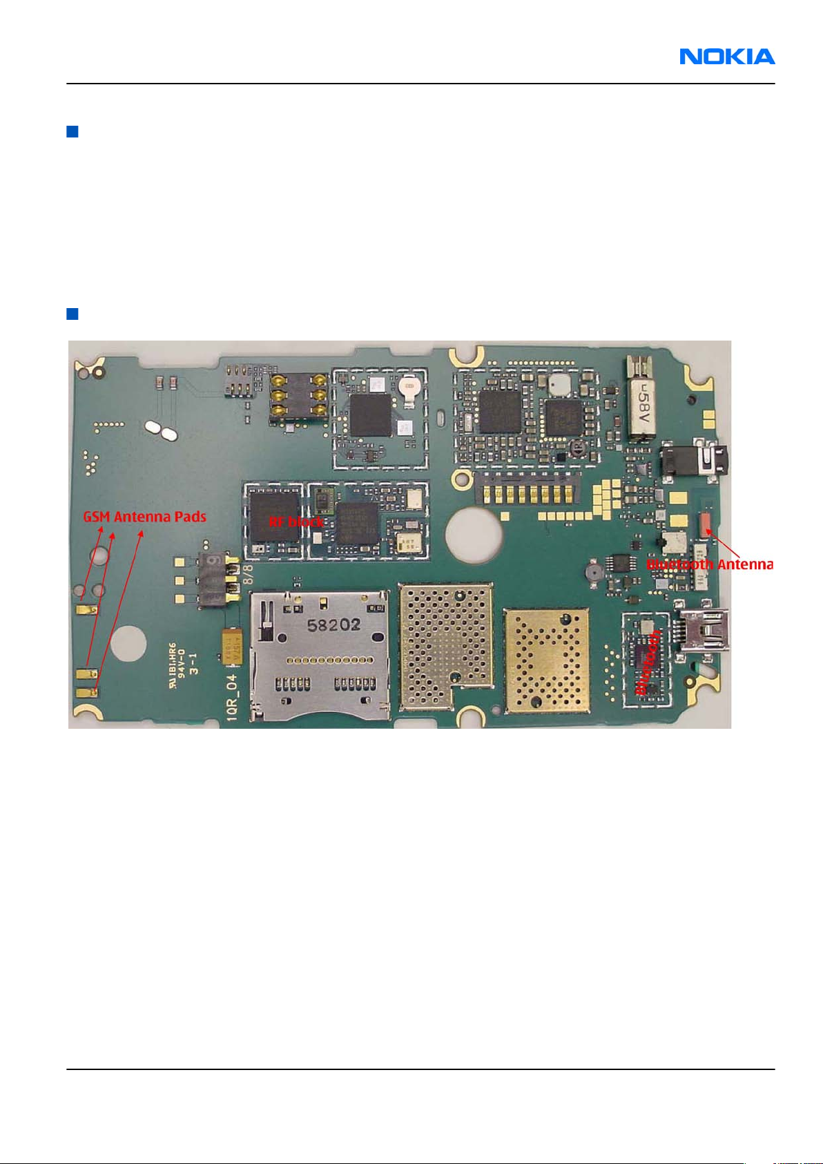
The RF section of the phone is around RF ASIC N7505, TX FEM N7520, and all of this RF section is built inside
of non-removable shields A7506, A7507. Therefore, the engine will be replaced after carefully checked power
and receiver tuning at antenna port.
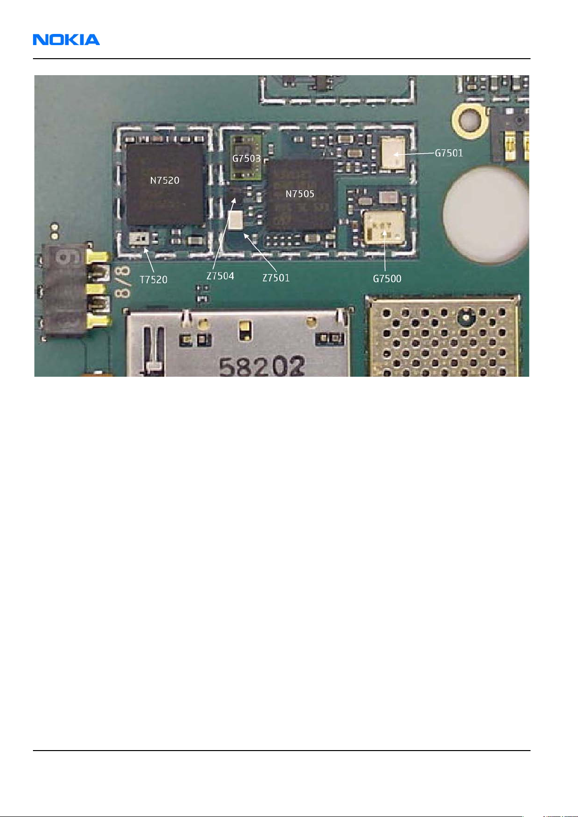
RF key component placement
Issue 1 COMPANY CONFIDENTIAL Page 7 –5
Copyright © 2006 Nokia. All rights reserved.
Page 6
RM-88
Nokia Customer Care RF Troubleshooting and Manual Tuning Guide
Figure 42 RM-88 RF components
Page 7 –6 COMPANY CONFIDENTIAL Issue 1
Copyright © 2006 Nokia. All rights reserved.
Page 7
RM-88
RF Troubleshooting and Manual Tuning Guide Nokia Customer Care
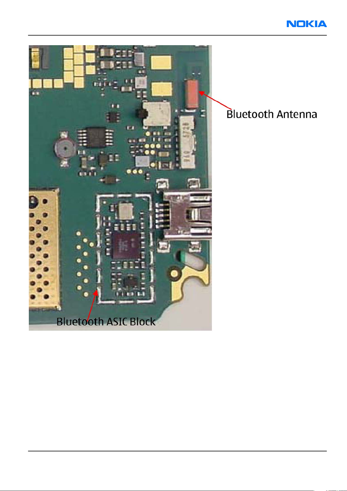
Figure 43 RM-88 BT component placement
Issue 1 COMPANY CONFIDENTIAL Page 7 –7
Copyright © 2006 Nokia. All rights reserved.
Page 8
RM-88
Nokia Customer Care RF Troubleshooting and Manual Tuning Guide
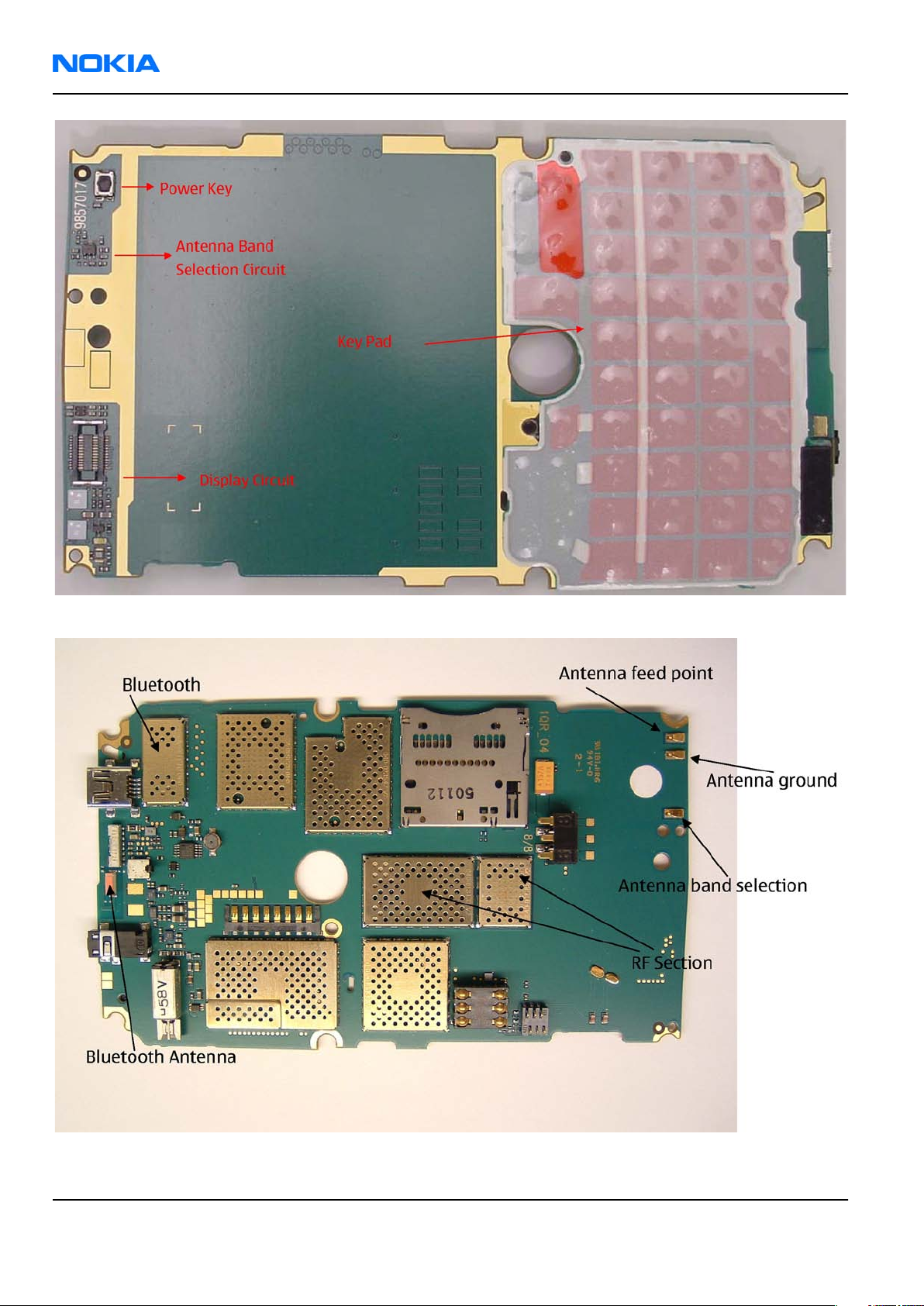
Figure 44 RM-88 component placement (top)
Figure 45 RM-88 component placement (bottom)
Page 7 –8 COMPANY CONFIDENTIAL Issue 1
Copyright © 2006 Nokia. All rights reserved.
Page 9
RM-88
RF Troubleshooting and Manual Tuning Guide Nokia Customer Care
Receiver troubleshooting
Introduction to Rx troubleshooting
Rx can be tested by making a phone call or in the local mode. For the local mode testing, use Phoenix service
software.
The main Rx troubleshooting measurement is RSSI measurement. This test measures the signal strength of
the received signal.
In GSM, the input signal can be either a real GSM signal or a CW (Continuous Wave) signal, which is 67.771
kHz above the carrier frequency.
For service tool usage instructions, refer to section Service Tools and Service Concepts.
General instructions for RX troubleshooting
Steps
1. Connect a test jig to a computer with a DKE-2 cable or to a FPS-10 flash prommer with a modular cable
(XCS-4).
Make sure that you have a PKD-1 dongle connected to the computer's parallel port.
2. Connect a DC power supply to a module test jig (MJ-67).
Note: Set the DC supply voltage to 12 V and set the jumper connector on the test jig's reg.pass
switch to “ON” position.
3. Connect an RF cable between the RF connector of the module test jig (MJ-67) and measurement equipment
or alternatively use a 50 ohms (at least 2 W) dummy load in the module test jig RF connector, otherwise
GSM may be damaged.
Note: Make sure that all connections are made to the correct RF connector.
4. Set Rx on.
i Set the phone module to the test jig and start
Phoenix service software
.
ii Initialize connection to the phone. (With FPS-10 use FBUS driver when using DKE-2 and COMBOX driver).
iii From the File menu, choose product: File -> Choose Product -> xx-x* (* = type designator of the
phone, scan product).
iv From the toolbar, set operating mode to “Local”.
5. EGSM900, GSM850/1800/1900 troubleshooting
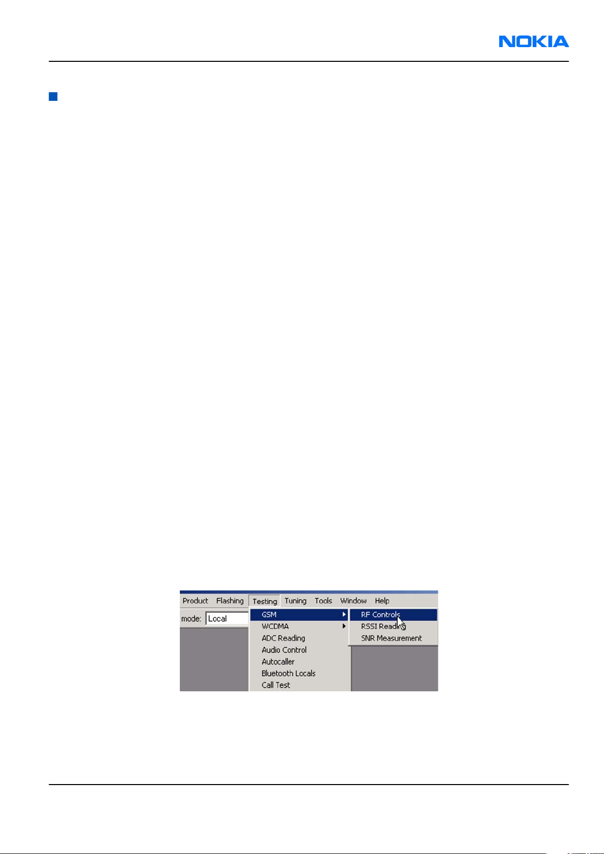
i From the Testing menu, activate the
ii In the
• Select band "GSM850", “GSM900” or “GSM1800” or “GSM1900” (Default = “GSM850”).
• Set Active unit to “Rx” (Default = “Rx”).
• Set Operation mode to “Burst” (Default = “Burst”).
RF Controls
window:
RF Controls
window: Testing -> GSM -> RF Controls .
Issue 1 COMPANY CONFIDENTIAL Page 7 –9
Copyright © 2006 Nokia. All rights reserved.
Page 10
RM-88
Nokia Customer Care RF Troubleshooting and Manual Tuning Guide
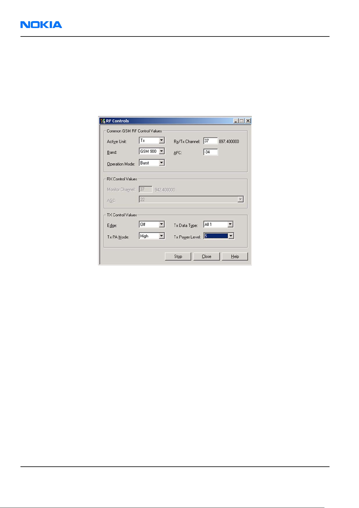
• Set Rx/Tx channel to 190 on GSM850, 37 on GSM900 band or 700 on GSM1800 band or 661 on GSM1900
(Defaults).
• Set Edge to “Off” (Default). (Not active in RXmode).
• Set Tx PA mode to “Free” (Default). (Not active in RXmode).
• Apply 942.46771 MHz (channel 37 + 67.710 kHz offset), 881.66771MHz (channel 190 + 67.710 kHz),
1842.86771 MHz (channel 700 + 67.710 kHz offset) or 1960.06771 MHz (channel 661 + 67.71 kHz) –
90 dBm signal to the RF-connector (remember to compensate for cable attenuation).
Figure 46 RF Controls window
GSM Rx chain activation for manual measurements / GSM RSSI measurement
Context
RSSI signal measurement is the main Rx troubleshooting measurement. The test measures the strength of
the received signal.
Steps
1. Start
2. Choose Testing→GSM→RSSI Reading .
3. Set the RF signal generator for channel frequency +67.771 kHz CW mode with –80 dBm signal.
Phoenix
Alternatively set the cellular tester downlink channel to the appropriate channel. Make sure that the tester
is set to continuous mode, not to burst mode.
service software.
Page 7 –10 COMPANY CONFIDENTIAL Issue 1
Copyright © 2006 Nokia. All rights reserved.
Page 11
RM-88
RF Troubleshooting and Manual Tuning Guide Nokia Customer Care
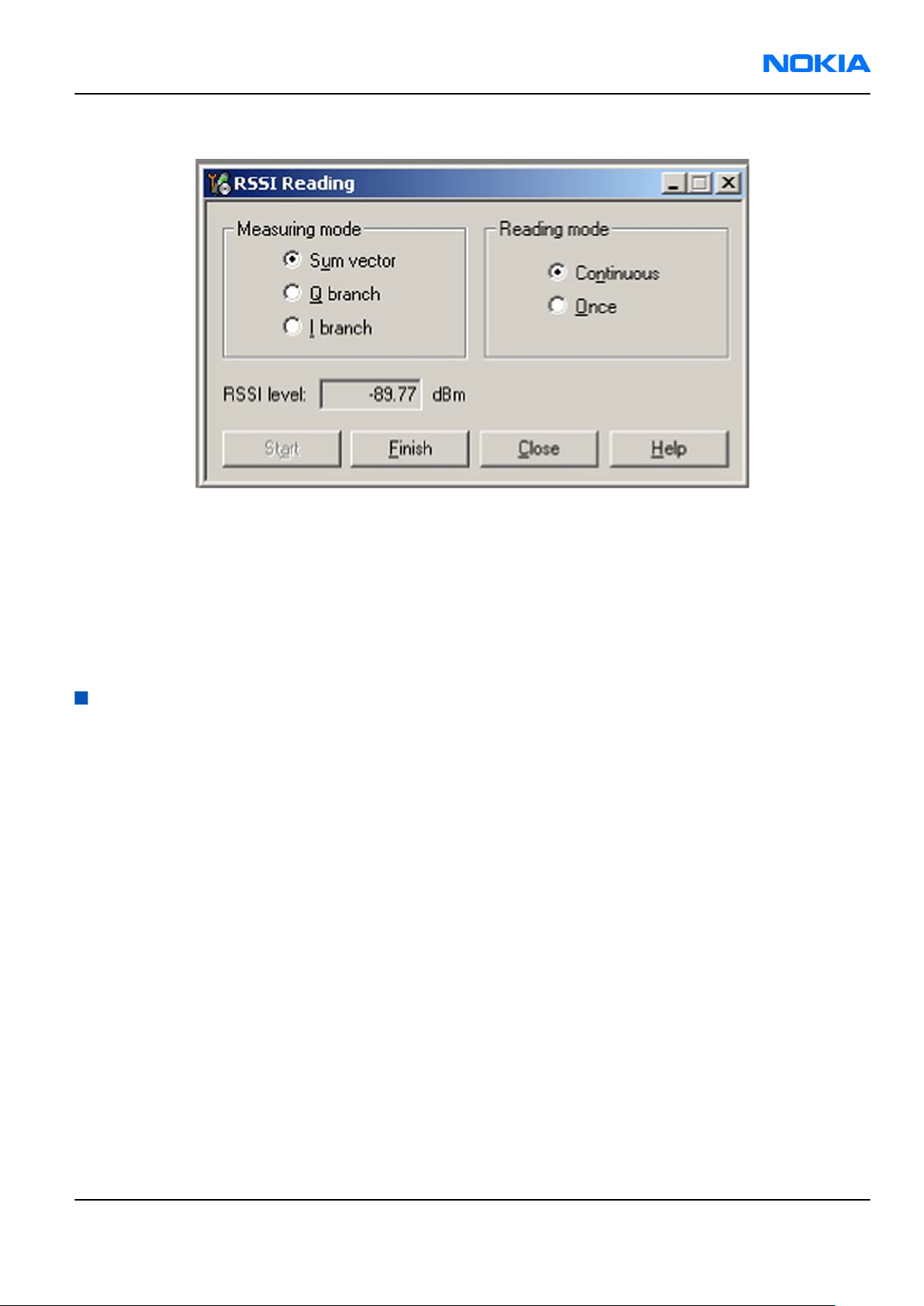
4. In the
5. To start the measurement, activate GSM Rx chain, click Start.
RSSI Reading
window, select the appropriate band and channel.
Figure 47
RSSI Reading
window
Results
RSSI reading values of the selected band and channel are displayed. The RSSI level must be the same value
which is set at the signal generator (-90 dBm).
If RSSI reading is far away from -90dBm, try to do RX tuning. Change engine if problem still shows up after
re-tuning.
Transmitter troubleshooting
General instructions for TX troubleshooting
Context
• Tx troubleshooting requires Tx operation.
• Do not transmit on frequencies that are in use!
• Transmitter can be controlled in the local mode for diagnostic purposes.
• The most useful Phoenix tool for GSM transmitter testing is "RF Controls".
• Remember that retuning is not a fix! Phones are tuned correctly in production.
The first set of steps instructs how to assemble the test setup. This setup is general for all Tx troubleshooting
tasks.
Alternative steps provide specific troubleshooting instructions for
Caution: Never activate the GSM transmitter without a proper antenna load. There should be always
50 ohm load connected to the RF connector (antenna, RF-measurement equipment or at least 2
watts dummy load), otherwise GSM PA may be damaged.
Phoenix
service software.
Steps
1. Connect a test jig to a computer with a DKE-2 cable or to a FPS-10 flash prommer with a modular cable
(XCS-4).
Make sure that you have a PKD-1 dongle connected to the computer's parallel port.
Issue 1 COMPANY CONFIDENTIAL Page 7 –11
Copyright © 2006 Nokia. All rights reserved.
Page 12

RM-88
Nokia Customer Care RF Troubleshooting and Manual Tuning Guide
2. Connect a DC power supply to a module jig (MJ-67).
Note: When repairing or tuning a transmitter, use an external DC supply with at least 3 A current
capability.
Set the DC supply voltage to 12V and set the jumper connector on the test jig's reg.pass switch to
“ON” position.
3. Connect an RF cable between the RF connector of the module test jig (MJ-69) and measurement equipment
or alternatively use a 50 ohms (at least 2 W) dummy load in the module test jig RF connector, otherwise
GSM may be damaged.
Note: There are two antenna connectors in the module jig:
• one for GSM
• one for Bluetooth
Make sure that all connections are made to the correct RF connector.
Normally a spectrum analyser is used as measurement equipment.
Note: The maximum input power of a spectrum analyser is +30 dBm.
To prevent any damage, it is recommended to use 10 dB attenuator on the spectrum analyzer input.
4. Set Tx on.
i Set the phone module to the test jig and start
Phoenix service software
.
ii Initialize connection to the phone. (With FPS-10 use FBUS driver when using DAU-9S and COMBOX
driver).
iii From the File menu, choose product: File -> Choose Product -> xx-x* (* = type designator of the
phone).
iv From the toolbar, set operating mode to “Local”.
5. EGSM900, GSM850/1800/1900 troubleshooting
i From the Testing menu, activate the
ii In the
• Select band "GSM850", “GSM900” or “GSM1800” or “GSM1900” (Default = “GSM850”).
• Set Active unit to “Tx” (Default = “Rx”).
• Set Operation mode to “Burst” (Default = “Burst”).
• Set Tx data type to “Random” (Default = “All1”).
• Set Rx/Tx channel to 190 on GSM850, 37 on GSM900 band or 700 on GSM1800 band or 661 on GSM1900
• Set Edge to “Off” (Default).
• Set Tx PA mode to “Free” (Default).
• Set power level to 5 (Default = 19) on GSM850/900 or to 0 (Default = 15) on GSM1800 or GSM1900.
RF Controls
(Defaults).
window:
RF Controls
window: Testing -> GSM -> RF Controls .
Page 7 –12 COMPANY CONFIDENTIAL Issue 1
Copyright © 2006 Nokia. All rights reserved.
Page 13

RM-88
RF Troubleshooting and Manual Tuning Guide Nokia Customer Care
Figure 48 RF Controls window
Issue 1 COMPANY CONFIDENTIAL Page 7 –13
Copyright © 2006 Nokia. All rights reserved.
Page 14

RM-88
Nokia Customer Care RF Troubleshooting and Manual Tuning Guide
TX 850/900 troubleshooting
Troubleshooting flow
Page 7 –14 COMPANY CONFIDENTIAL Issue 1
Copyright © 2006 Nokia. All rights reserved.
Page 15

RM-88
RF Troubleshooting and Manual Tuning Guide Nokia Customer Care
TX 1800/1900 troubleshooting
Troubleshooting flow
Checking antenna functionality
The main antenna has one antenna: GSM .
In the GSM antenna, there is one Feed and two GND contacts.
Issue 1 COMPANY CONFIDENTIAL Page 7 –15
Copyright © 2006 Nokia. All rights reserved.
Page 16

RM-88
Nokia Customer Care RF Troubleshooting and Manual Tuning Guide
The contacts of the GSM antenna are separated in the (RDC = 0 ohm) short-circuit.
Figure 49 Main antenna
Figure 50 Feed and GND spots of the main antenna
Page 7 –16 COMPANY CONFIDENTIAL Issue 1
Copyright © 2006 Nokia. All rights reserved.
Page 17

RM-88
RF Troubleshooting and Manual Tuning Guide Nokia Customer Care
The antenna is functioning normally when the contacts function (RDC = 0 ohm) and the antenna is visually
intact.
BT antenna
BT antenna has one Feed and one GND contact. The antenna is functioning normally when the contacts
function (RDC = 0 ohm) and the antenna is visually intact.
RF tunings
Introduction to RF tunings
Important: Only perform RF tunings if:
• one or more of the RF components is changed
• flash Memory chip is changed or otherwise corrupted.
RF calibration is always performed with the help of a product-specific module jig, never with an RF coupler.
Using an RF coupler in the calibration phase will cause a complete mistuning of the RF side.
Important: After RF component changes, always use autotuning. Manual tunings are only required
in rare cases.
Cable and adapter losses
RF cables and adapters have some losses. They have to be taken in account when the phone is tuned. As all
the RF losses are frequency dependent, the user have to be very careful and understand the measurement
setup. In the following table there are RF attenuations of the module jig:
Band Attenuation
GSM850 0.2 dB
GSM900 0.2 dB
GSM1800 0.3 dB
GSM1900 0.6 dB
RF autotuning
Prerequisites
For information on the recommended test set-up, refer to the corresponding information on PWS/NOL.
Before you can use the auto-tune feature, the GPIB driver from the GPIB card vendor must be installed and
running.
The autotune .ini file must be in a correct place: C:\Program Files\Nokia\Phoenix\products\xx-x*
\autotune_xx-x*.ini (
*= indicates the type designator of the phone, e.g. RM-1
)
Context
RF autotuning is performed with the aid of Digital Radio Communication Tester. Autotuning covers all RF
tunings that are needed to perform after RF component repairs.
Note: Do not perform RF autotuning without a proper reason. Phones are tuned in production and
an RF tuning may be performed only after component repairs or if the RF tuning information is lost.
Steps
1. Connect the communication tester to the GPIB bus.
Issue 1 COMPANY CONFIDENTIAL Page 7 –17
Copyright © 2006 Nokia. All rights reserved.
Page 18

RM-88
Nokia Customer Care RF Troubleshooting and Manual Tuning Guide
2. Start Phoenix service software.
3. From the Tools menu, choose Options -> GPIB Card.
4. In the Card Type line, select CEC8Bit, then click Start.
After clicking Start, the name of the communication tester appears in the list of found Listeners.
5. To specify the cable loss from module jig to the communication tester, choose "Set Loss" from the Tuning
menu.
6. Click the Cable tab and add the extra cable attenuation.
Note: Cable losses have to be determined on the basis of a cable used.
Page 7 –18 COMPANY CONFIDENTIAL Issue 1
Copyright © 2006 Nokia. All rights reserved.
Page 19

RM-88
RF Troubleshooting and Manual Tuning Guide Nokia Customer Care
7. To start autotuning, choose Auto-Tune from the Tuning menu.
8. In the Auto-Tune window, click Options.
9. In the Auto-Tune options window, see that the "Enable showing of messages" check box is checked,
then click OK.
10. To complete the RF autotuning, click OK.
Results
"Autotuning completed successfully" message appears.
Issue 1 COMPANY CONFIDENTIAL Page 7 –19
Copyright © 2006 Nokia. All rights reserved.
Page 20

RM-88
Nokia Customer Care RF Troubleshooting and Manual Tuning Guide
System mode independent manual tunings
Rf channel filter calibration
Context
Rf channel filter calibration tunes the internal low pass filters of Rx and Tx ASICs that limit the bandwidth of
BB IQ signals.
One common calibration is made for GSM.
Table 12 Rf channel filter calibration tuning limits
Min Typ Max
Tx filter 0 10 31
Rx filter 0 16 31
Steps
1. From the Operating mode drop-down menu, set mode to Local.
2. Choose Tuning→Rf Channel Filter Calibration .
3. Click Tune.
4. To save the values to the PMM (Phone Permanent Memory) area, click Write.
5. To close the
Rf Channel Filter Calibration
window, click Close.
Results
Figure 51 Rf channel filter calibration typical values
Page 7 –20 COMPANY CONFIDENTIAL Issue 1
Copyright © 2006 Nokia. All rights reserved.
Page 21

RM-88
RF Troubleshooting and Manual Tuning Guide Nokia Customer Care
PA (power amplifier) detection
Context
The PA detection procedure detects which PA manufacturer is used for phone PAs.
If a PA is changed or if the permanent memory (PMM) data is corrupted, PA detection has to be performed
before Tx tunings.
Steps
1. From the Operating mode drop-down menu, set mode to Local.
2. Choose Tuning→PA Detection .
3. Click Tune.
4. Check that the detected PA manufacturers are corresponding to the actual chips on the board.
5. To end the procedure, click Close.
GSM receiver tunings
Rx calibration (GSM)
Context
Rx Calibration is used to find out the real gain values of the GSM Rx AGC system and tuning response of the
AFC system (AFC D/A init value and AFC slope)
Steps
1. Connect the GSM connector of the module jig to a signal generator.
2. Start
3. From the Operating mode drop-down menu, set mode to Local.
4. Choose Tuning→GSM→Rx Calibration .
5. Check the Load from Phone check box, and uncheck Save to Phone.
6. From the Band drop-down menu, choose e.g. GSM900.
Phoenix
service software.
Issue 1 COMPANY CONFIDENTIAL Page 7 –21
Copyright © 2006 Nokia. All rights reserved.
Page 22

RM-88
Nokia Customer Care RF Troubleshooting and Manual Tuning Guide
7. Click Start.
Page 7 –22 COMPANY CONFIDENTIAL Issue 1
Copyright © 2006 Nokia. All rights reserved.
Page 23

RM-88
RF Troubleshooting and Manual Tuning Guide Nokia Customer Care
8. Click Calibrate.
9. Connect the signal generator to the phone, and set frequency and amplitude as instructed in the
Rx Calibration with band EGSM900 pop-up window.
Important: The calibration uses a non-modulated CW signal. Increase the signal generator level by
cable attenuation and module jig probe attenuation.
Issue 1 COMPANY CONFIDENTIAL Page 7 –23
Copyright © 2006 Nokia. All rights reserved.
Page 24

RM-88
Nokia Customer Care RF Troubleshooting and Manual Tuning Guide
10. To perform the tuning, click OK.
11. Check that the tuning values are within the limits specified in the following table:
Table 13 RF tuning limits in Rx calibration
Min Typ Max Unit
GSM850
AFC Value -200 -105...62 200
AFC slope 0 122 200
RSSI0 106 107...110 114 dB
GSM900
AFC Value -200 -105...62 200
AFC slope 0 122 200
RSSI0 106 107...110 114 dB
GSM1800
RSSI0 104 104...109 114 dB
GSM1900
RSSI0 104 104...109 114 dB
Page 7 –24 COMPANY CONFIDENTIAL Issue 1
Copyright © 2006 Nokia. All rights reserved.
Page 25

RM-88
RF Troubleshooting and Manual Tuning Guide Nokia Customer Care
12. To save values to the phone, check the Save to Phone check box, and click Stop.
Next actions
Repeat steps 3 to 8 for GSM850, GSM1800 and GSM1900
Rx band filter response compensation (GSM)
Prerequisites
Rx calibration must be done before the Rx Band Filter Response Compensation
Context
In each GSM Rx band, there’s a band rejecting filter in front of RF ASIC front end. The amplitude ripple caused
by these filters causes ripple to the RSSI measurement and therefore calibration is needed.
The calibration has to be repeated for each GSM band.
Steps
1. Connect module jig’s GSM connector to signal generator.
2. From the dropdown menus, set "Operating mode" to Local, "System mode" to GSM, and Band to GSM900.
Issue 1 COMPANY CONFIDENTIAL Page 7 –25
Copyright © 2006 Nokia. All rights reserved.
Page 26

RM-88
Nokia Customer Care RF Troubleshooting and Manual Tuning Guide
3. From the Tuning menu, choose GSM -> Rx Band Filter Response Compensation.
4. Check “Manual” and “Load from Phone” check boxes. Clear “Save to Phone” check box
5. Click Start.
Page 7 –26 COMPANY CONFIDENTIAL Issue 1
Copyright © 2006 Nokia. All rights reserved.
Page 27

RM-88
RF Troubleshooting and Manual Tuning Guide Nokia Customer Care
6. Click Tune.
7. Connect signal generator to the phone and set frequency and amplitude as instructed in the "Rx Band
Filter Response Compensation for EGSM900" popup window.
8. To perform tuning, click OK.
9. Go through all 9 frequencies.
Issue 1 COMPANY CONFIDENTIAL Page 7 –27
Copyright © 2006 Nokia. All rights reserved.
Page 28

RM-88
Nokia Customer Care RF Troubleshooting and Manual Tuning Guide
10. Check that the tuning values are within the limits specified in this table:
Min Typ Max Unit
GSM850
Ch. 118 /
867.26771 MHz
Ch. 128 /
869.26771 MHz
Ch. 140 /
871.66771 MHz
Ch. 172 /
878.06771 MHz
Ch. 190 /
881.66771 MHz
Ch. 217 /
887.06771 MHz
Ch. 241 /
891.86771 MHz
Ch. 251 /
893.86771 MHz
Ch. 261/
895.86771 MHz
GSM900
-10 -1 5 dB
-3 0 5 dB
-3 0 5 dB
-3 0 5 dB
-3 0 5 dB
-3 0 5 dB
-3 0 5 dB
-3 0 5 dB
-10 -1 5 dB
Ch. 965 /
923.26771 MHz
Ch. 975 /
925.26771 MHz
Ch. 987 /
927.66771 MHz
Ch. 1009 /
932.06771 MHz
Ch. 37 /
942.46771 MHz
Ch. 90 /
953.06771 MHz
Ch. 114 /
957.86771 MHz
Ch. 124 /
959.86771 MHz
Ch. 136 /
962.26771 MHz
GSM1800
-10 -1 5 dB
-3 0 5 dB
-3 0 5 dB
-3 0 5 dB
-3 0 5 dB
-3 0 5 dB
-3 0 5 dB
-3 0 5 dB
-10 -1 5 dB
Page 7 –28 COMPANY CONFIDENTIAL Issue 1
Copyright © 2006 Nokia. All rights reserved.
Page 29

RM-88
RF Troubleshooting and Manual Tuning Guide Nokia Customer Care
Min Typ Max Unit
Ch. 497 /
1802.26771 MHz
Ch. 512 /
1805.26771 MHz
Ch. 535 /
1809.86771 MHz
Ch. 606 /
1824.06771 MHz
Ch. 700 /
1842.86771 MHz
Ch. 791 /
1861.06771 MHz
Ch. 870 /
1876.86771 MHz
Ch. 885 /
1879.86771 MHz
Ch. 908 /
1884.46771 MHz
GSM1900
-10 -1 5 dB
-3 0 5 dB
-3 0 5 dB
-3 0 5 dB
-3 0 5 dB
-3 0 5 dB
-3 0 5 dB
-3 0 5 dB
-10 -1 5 dB
Ch. 496 /
1927.06771 MHz
Ch. 512 /
1930.26771 MHz
Ch. 537 /
1935.26771 MHz
Ch. 586 /
1945.06771 MHz
Ch. 661 /
1960.06771 MHz
Ch. 736 /
1975.06771 MHz
Ch. 794 /
1986.66771 MHz
Ch. 810 /
1989.86771 MHz
Ch. 835 /
1994.86771 MHz
-10 -1 5 dB
-3 0 5 dB
-3 0 5 dB
-3 0 5 dB
-3 0 5 dB
-3 0 5 dB
-3 0 5 dB
-3 0 5 dB
-10 -1 5 dB
Issue 1 COMPANY CONFIDENTIAL Page 7 –29
Copyright © 2006 Nokia. All rights reserved.
Page 30

RM-88
Nokia Customer Care RF Troubleshooting and Manual Tuning Guide
11. Check the "Save to Phone" check box and click Stop if the values are within the limits.
Next actions
Repeat the steps 4 to 10 for GSM850, GSM1800 and GSM1900.
GSM transmitter tunings
Tx IQ tuning (GSM)
Context
The Tx path branches to I and Q signals at RF I/Q modulator. Modulator and analog hardware located after
it cause unequal amplitude and phase disturbance to I and Q signal paths. Tx IQ tuning tuning balances the
I and Q branches.
Tx IQ tuning must be performed on all GSM bands. .
Steps
1. From the dropdown menus, set "Operating mode" to Local, "System mode" to GSM, and Band to GSM900.
2. From the Tuning menu, choose GSM -> Tx IQ Tuning.
3. Set Mode to Automatic and Edge to Off.
4. Click Start.
Wait until automatic tuning has finished and moved the sliders.
Values are written to the phone memory automatically.
Page 7 –30 COMPANY CONFIDENTIAL Issue 1
Copyright © 2006 Nokia. All rights reserved.
Page 31

RM-88
RF Troubleshooting and Manual Tuning Guide Nokia Customer Care
5. When the values have been written to the phone memory, click the Finish button to end the tuning.
6. Change band to GSM850 and repeat steps 4 to 5.
7. Change band to GSM1800 and repeat steps 4 to 5.
8. Change band to GSM1900 and repeat steps 4 to 5.
9. To close the tuning window, click Close.
Next actions
Tuning sliders should be close to the center of the scale after the tuning and within the limits specified in
the table below. If they are not within the limits, check Tx IQ quality manually.
Min Typ Max Unit
GSM850
I DC offset / Q DC
offset
Ampl -1 0 1 dB
Phase 85 90 95
GSM900
Issue 1 COMPANY CONFIDENTIAL Page 7 –31
-6 -4 6 %
○
Copyright © 2006 Nokia. All rights reserved.
Page 32

RM-88
Nokia Customer Care RF Troubleshooting and Manual Tuning Guide
Min Typ Max Unit
I DC offset / Q DC
offset
Ampl -1 0 1 dB
Phase 85 90 95
GSM1800/GSM1900
I/Q DC -6 0.5 6 %
Ampl -1 0 1 dB
Phase 95 100 110
-6 -4 6 %
○
○
Tx power level tuning (GSM)
Context
Because of variations at IC process and discrete component values, actual transmitter RF gain of each phone
is different. Tx power level tuning is used to find out mapping factors called 'power coefficients’. These adjust
the GSM transmitter output power to fulfill the specifications.
For EDGE transmission the bias settings of the FEM are adjusted in order to improve linearity. This affects the
PA gain and hence the power levels have to be aligned separately for EDGE transmission.
Tx power level tuning has to be performed on all GSM bands.
Steps
1. Connect the phone to a spectrum analyzer.
2. From the dropdown menus, set "Operating mode" to Local, "System mode" to GSM, and Band to GSM900.
3. From the Tuning menu, choose GSM -> Tx Power Level Tuning.
4. Set Mode to Automatic and Edge to Off.
5. Set the spectrum analyzer for power level tuning:
Frequency channel frequency (836.6MHz GSM850, 897.4MHz
GSM900, 1747.8MHz GSM1800, 1880MHz
GSM1900)
Span 0 Hz
Sweep time 2ms
Trigger Video triggering (-10dBm)
Resolution BW 3MHz
Video BW 3MHz
Page 7 –32 COMPANY CONFIDENTIAL Issue 1
Copyright © 2006 Nokia. All rights reserved.
Page 33

RM-88
RF Troubleshooting and Manual Tuning Guide Nokia Customer Care
Reference level offset sum cable attenuation with module jig
attenuation
Reference level 33dBm
A power meter with a peak power detector can be also used. Remember to take the attenuations in the
account!
6. Click Start.
7. Adjust power levels 5, 15 and 19 to correspond the "Target dBm" column by pressing + or – keys.
Issue 1 COMPANY CONFIDENTIAL Page 7 –33
Copyright © 2006 Nokia. All rights reserved.
Page 34

RM-88
Nokia Customer Care RF Troubleshooting and Manual Tuning Guide
8. Click Calculate Coefficients.
9. Check that the coeffiecient values are within the limits specified in the following table.
Min Typ Max
GSM850 EDGE off
PL5 coefficient 0.45 0.626 0.73
PL15 coefficient 0.234
PL19 coefficient 0.12 0.195 0.3
GSM850 EDGE on
PL8 coefficient 0.35 0.419 0.6
PL15 coefficient 0.247
PL19 coefficient 0.12 0.204 0.3
GSM900 EDGE off
PL5 coefficient 0.45 0.626 0.73
PL15 coefficient 0.234
PL19 coefficient 0.12 0.195 0.3
GSM900 EDGE on
PL8 coefficient 0.35 0.419 0.6
PL15 coefficient 0.247
PL19 coefficient 0.12 0.204 0.3
GSM1800 EDGE off
PL0 coefficient 0.45 0.51 0.7
Page 7 –34 COMPANY CONFIDENTIAL Issue 1
Copyright © 2006 Nokia. All rights reserved.
Page 35

RM-88
RF Troubleshooting and Manual Tuning Guide Nokia Customer Care
Min Typ Max
PL11 coefficient 0.219
PL15 coefficient 0.12 0.185 0.3
GSM1800 EDGE on
PL2 coefficient 0.35 0.394 0.6
PL11 coefficient 0.23
PL15 coefficient 0.12 0.194 0.3
GSM1900 EDGE off
PL0 coefficient 0.45 0.482 0.7
PL11 coefficient 0.218
PL15 coefficient 0.12 0.184 0.3
GSM1900 EDGE on
PL2 coefficient 0.35 0.377 0.6
PL11 coefficient 0.23
PL15 coefficient 0.12 0.193 0.3
If the values are within the limits, check that the "Save to Phone Permanent Memory" check box is
checked and click Stop.
Issue 1 COMPANY CONFIDENTIAL Page 7 –35
Copyright © 2006 Nokia. All rights reserved.
Page 36

RM-88
Nokia Customer Care RF Troubleshooting and Manual Tuning Guide
10. Set Edge mode on and start tuning again. Change video averaging to 50.
11. Tune EDGE power levels to the corresponding target power levels.
Only power levels 8, 15 and 19 are tuned in GSM900 and 2, 10 and 15 in GSM1800/1900. The rest are
calculated by clicking the Calculate Coefficients button. Check the coefficients against the RF tuning limits
table presented in Step 9.
12. When the tuning is completed, click Stop.
Next actions
Repeat steps 4 to 9 for GSM1800 and GSM1900. On those bands only power levels 0, 11 and 15 need to be
tuned.
Page 7 –36 COMPANY CONFIDENTIAL Issue 1
Copyright © 2006 Nokia. All rights reserved.
 Loading...