

Page 1

Nokia Customer Care
6 — BB Troubleshooting and
Manual Tuning Guide
Issue 1 COMPANY CONFIDENTIAL Page 6 –1
Copyright © 2006 Nokia. All rights reserved.
Page 2

RM-88
Nokia Customer Care BB Troubleshooting and Manual Tuning Guide
(This page left intentionally blank.)
Page 6 –2 COMPANY CONFIDENTIAL Issue 1
Copyright © 2006 Nokia. All rights reserved.
Page 3

RM-88
BB Troubleshooting and Manual Tuning Guide Nokia Customer Care
Table of Contents
Introduction to baseband troubleshooting.........................................................................................................6–5
Baseband main troubleshooting..........................................................................................................................6–6
General power checking troubleshooting...........................................................................................................6–7
Battery current measuring fault troubleshooting..............................................................................................6–8
Flash programming fault troubleshooting..........................................................................................................6–9
Keyboard troubleshooting....................................................................................................................................6–9
USB interface troubleshooting............................................................................................................................6–11
Charging troubleshooting...................................................................................................................................6–12
Dead or jammed troubleshooting......................................................................................................................6–13
IrDA troubleshooting...........................................................................................................................................6–14
Vibra troubleshooting..........................................................................................................................................6–15
MiniSD troubleshooting.......................................................................................................................................6–16
SIM troubleshooting.............................................................................................................................................6–17
Display module troubleshooting........................................................................................................................6–18
General instructions for display troubleshooting........................................................................................6–18
Display fault troubleshooting........................................................................................................................6–20
Display and keyboard backlight troubleshooting........................................................................................6–21
EL backlight fault troubleshooting................................................................................................................6–24
ALS troubleshooting........................................................................................................................................6–25
LED driver troubleshooting............................................................................................................................6–28
Bluetooth troubleshooting..................................................................................................................................6–29
Introduction to Bluetooth troubleshooting.................................................................................................6–29
Bluetooth settings for Phoenix......................................................................................................................6–29
Bluetooth self tests in Phoenix......................................................................................................................6–30
Bluetooth BER failure troubleshooting.........................................................................................................6–32
BT audio failure troubleshooting..................................................................................................................6–33
Audio troubleshooting.........................................................................................................................................6–34
Audio troubleshooting test instructions......................................................................................................6–34
Internal earpiece troubleshooting................................................................................................................6–37
Internal microphone troubleshooting..........................................................................................................6–38
IHF troubleshooting........................................................................................................................................6–39
External microphone troubleshooting..........................................................................................................6–40
External earpiece troubleshooting................................................................................................................6–41
Introduction to acoustics troubleshooting..................................................................................................6–42
Earpiece troubleshooting...............................................................................................................................6–43
Acoustics IHF troubleshooting.......................................................................................................................6–44
Microphone troubleshooting.........................................................................................................................6–45
Baseband manual tuning guide.........................................................................................................................6–46
Energy management calibration...................................................................................................................6–46
List of Tables
Table 9 Display module troubleshooting cases................................................................................................6–18
Table 10 Pixel defects..........................................................................................................................................6–19
Table 11 Calibration value limits........................................................................................................................6–46
List of Figures
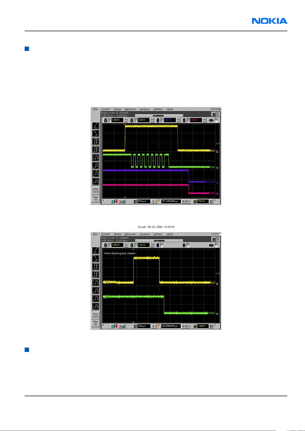
Figure 34 Flashing pic 1. Take single trig measurement for the rise of the BSI signal...................................6–9
Figure 35 Flashing pic 2. Take single trig measurement for the rise of the BSI signal...................................6–9
Issue 1 COMPANY CONFIDENTIAL Page 6 –3
Copyright © 2006 Nokia. All rights reserved.
Page 4

RM-88
Nokia Customer Care BB Troubleshooting and Manual Tuning Guide
Figure 36 Ambient Light Sensor Calibration window.......................................................................................6–26
Figure 37 BER test result......................................................................................................................................6–30
Figure 38 Bluetooth self tests in Phoenix..........................................................................................................6–31
Figure 39 Single-ended output waveform of the Ext_in_HP_out measurement when earpiece is
connected...................................................................................................................................................6–35
Figure 40 Differential output waveform of the Ext_in_IHF_out out loop measurement when speaker is
connected...................................................................................................................................................6–35
Figure 41 Single-ended output waveform of the HP_in_Ext_out loop when microphone is connected....
6–36
Page 6 –4 COMPANY CONFIDENTIAL Issue 1
Copyright © 2006 Nokia. All rights reserved.
Page 5

RM-88
BB Troubleshooting and Manual Tuning Guide Nokia Customer Care
Introduction to baseband troubleshooting
This chapter outlines the troubleshooting process for any baseband related problems reported from our
customer. All troubleshooting by service technicians will be limited to those parts that are not under any
shields.
Basic Troubleshooting for RM-88
The most likely problems that may be reported with RM-88 engine are listed below.
• Phone does not power up or gets jammed during startup.
• Abnormal current consumption.
• Flashing does not work.
• Charging does not work.
• Display does not work.
• Keypad does not work.
• Display backlight does not work.
• Keyboard EL dome sheet does light up.
• Mail indicator LED does not work.
• Phone gives SIM card error.
• Phone cannot access SD card.
• USB does not work.
• Audio (earpiece, microphone, and/or IHF) does not work.
• Audio headset does not work.
• Volume key does not work.
• Bluetooth does not work.
• IRDA does not work.
Issue 1 COMPANY CONFIDENTIAL Page 6 –5
Copyright © 2006 Nokia. All rights reserved.
Page 6
RM-88
Nokia Customer Care BB Troubleshooting and Manual Tuning Guide
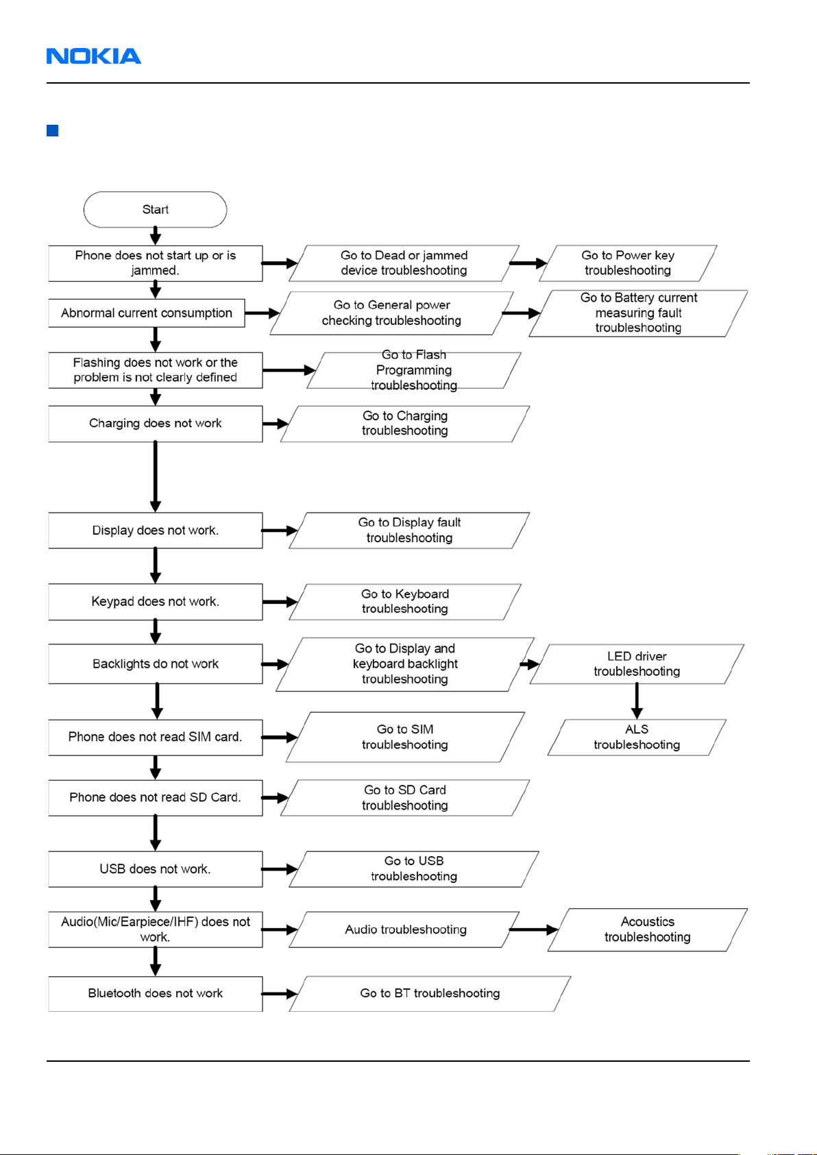
Baseband main troubleshooting
Troubleshooting flow
Page 6 –6 COMPANY CONFIDENTIAL Issue 1
Copyright © 2006 Nokia. All rights reserved.
Page 7
RM-88
BB Troubleshooting and Manual Tuning Guide Nokia Customer Care
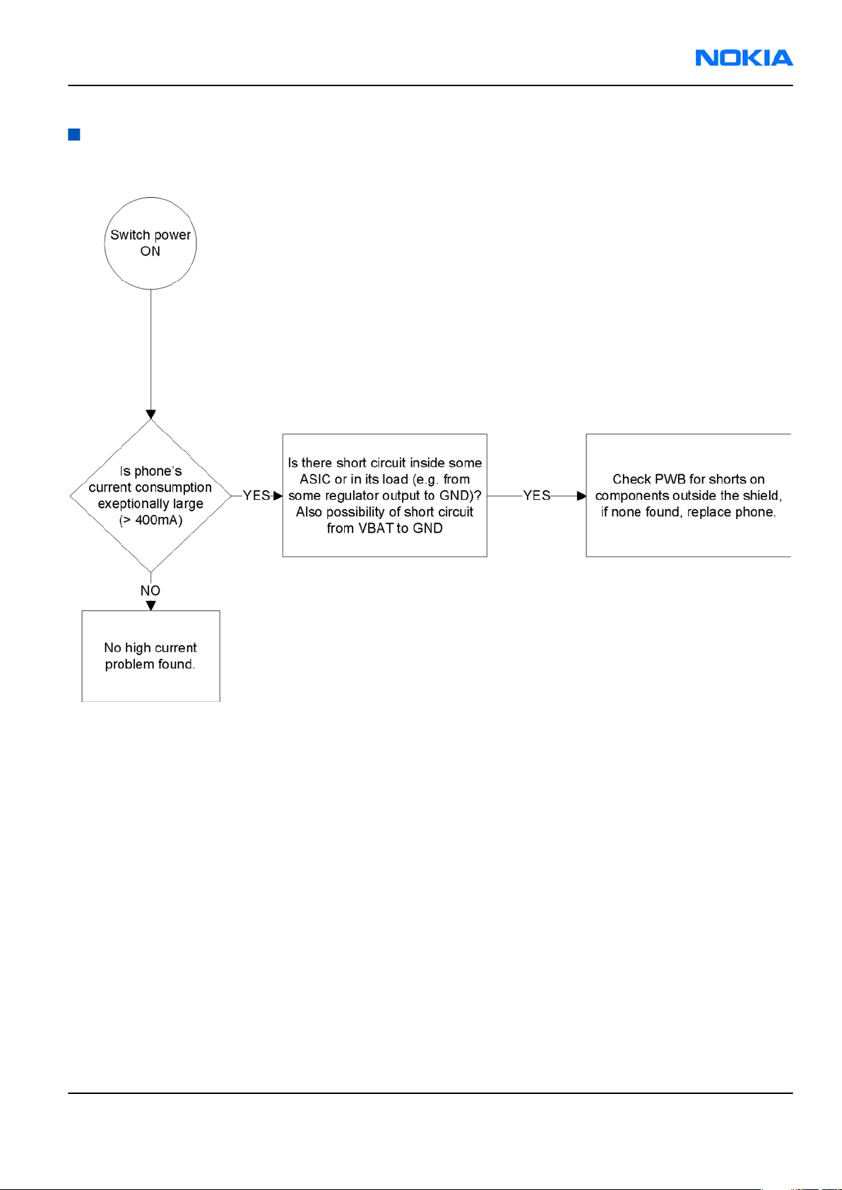
General power checking troubleshooting
Troubleshooting flow
Issue 1 COMPANY CONFIDENTIAL Page 6 –7
Copyright © 2006 Nokia. All rights reserved.
Page 8
RM-88
Nokia Customer Care BB Troubleshooting and Manual Tuning Guide
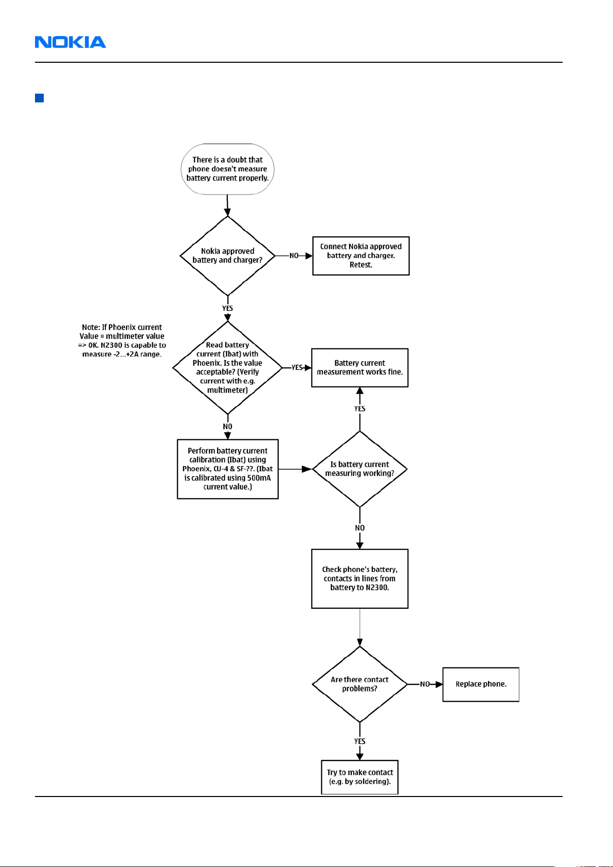
Battery current measuring fault troubleshooting
Troubleshooting flow
Page 6 –8 COMPANY CONFIDENTIAL Issue 1
Copyright © 2006 Nokia. All rights reserved.
Page 9
RM-88
BB Troubleshooting and Manual Tuning Guide Nokia Customer Care
Flash programming fault troubleshooting
Troubleshooting flow
Figure 34 Flashing pic 1. Take single trig measurement for the rise of the BSI signal.
Figure 35 Flashing pic 2. Take single trig measurement for the rise of the BSI signal.
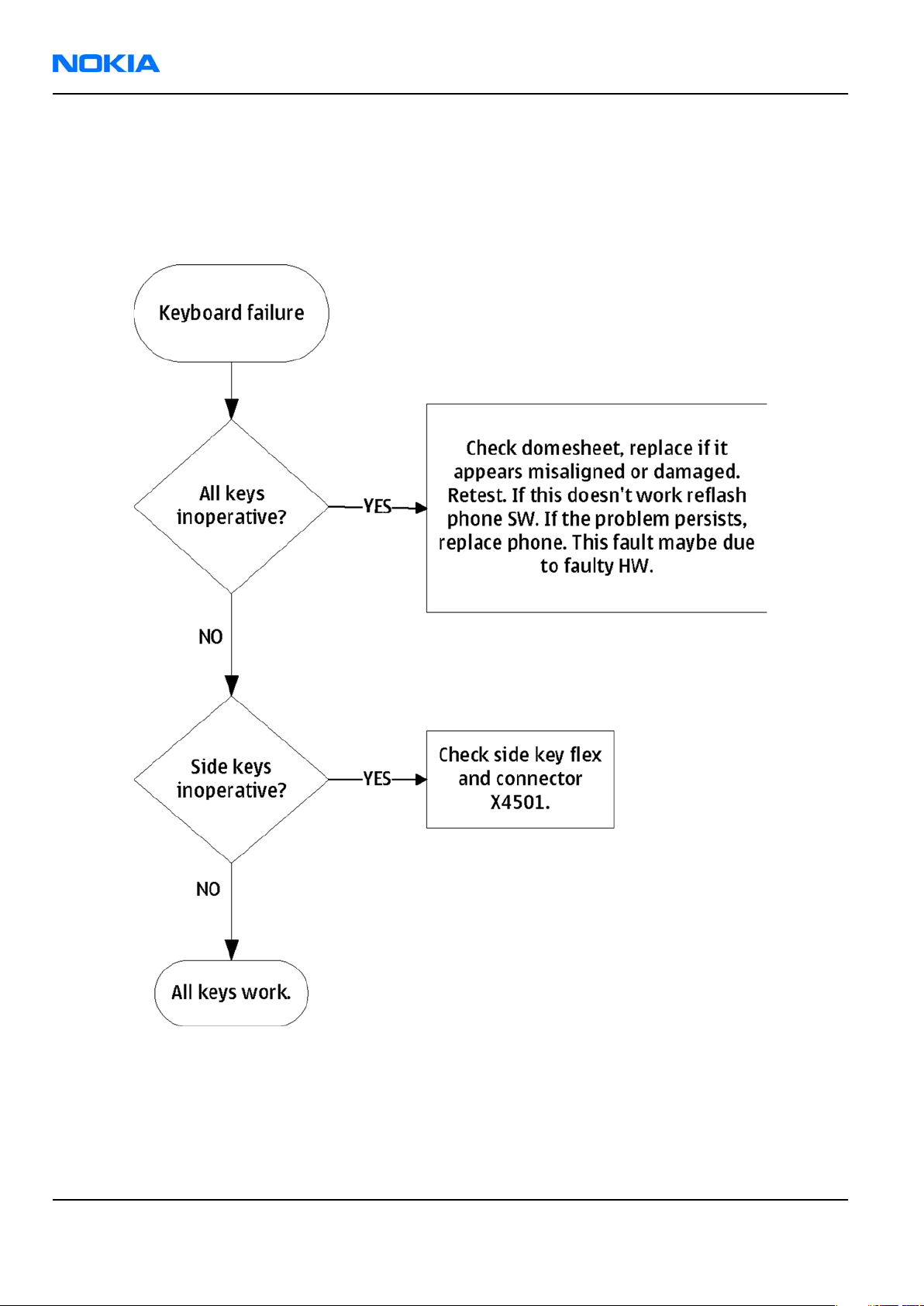
Keyboard troubleshooting
Context
There are two possible failure modes in the keyboard module:
• One or more keys can be stuck, so that the key does not react when a keydome is pressed. This kind of
failure is caused by mechanical reasons (dirt, corrosion).
Issue 1 COMPANY CONFIDENTIAL Page 6 –9
Copyright © 2006 Nokia. All rights reserved.
Page 10
RM-88
Nokia Customer Care BB Troubleshooting and Manual Tuning Guide
• Malfunction of several keys at the same time; this happens when one or more rows or columns are faulty
(shortcut or open connection). For a more detailed description of the keyboard and keymatrix, see
section Keyboard in System Module.
If the failure mode is not clear, start with the Keyboard Test in
Phoenix
.
Troubleshooting flow
Page 6 –10 COMPANY CONFIDENTIAL Issue 1
Copyright © 2006 Nokia. All rights reserved.
Page 11
RM-88
BB Troubleshooting and Manual Tuning Guide Nokia Customer Care
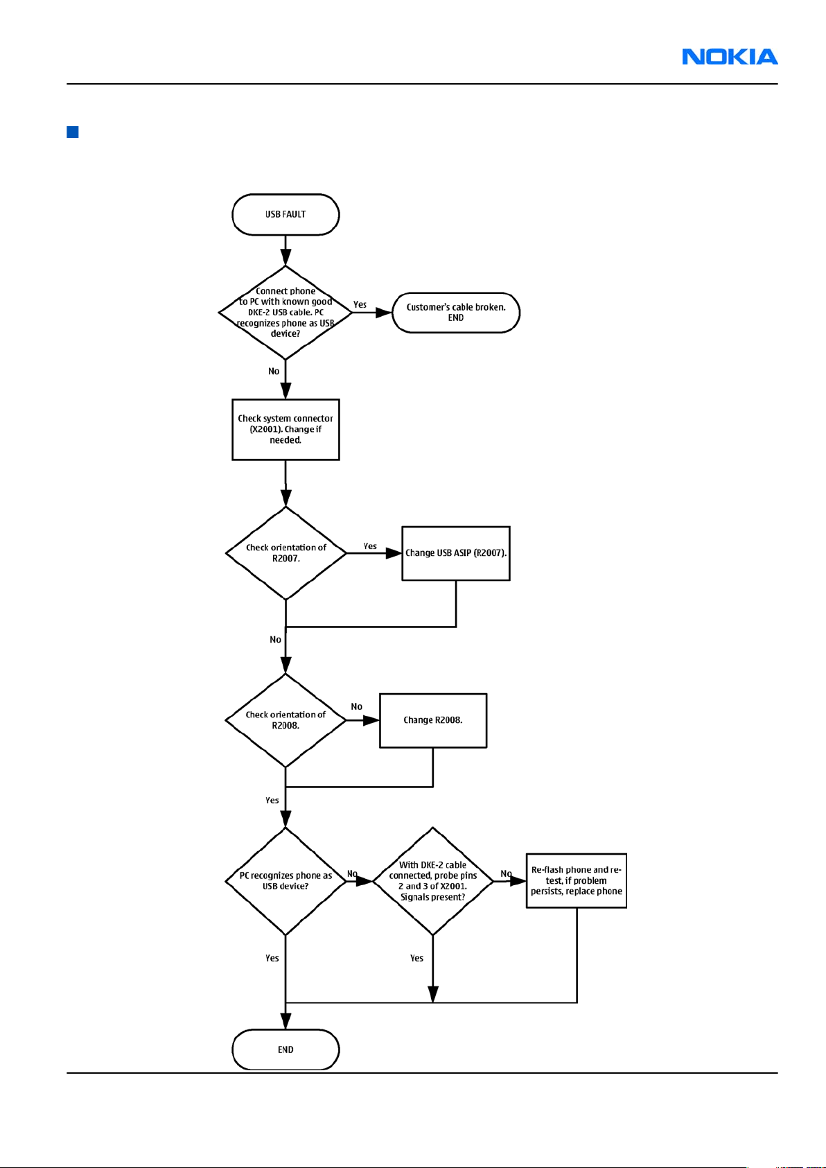
USB interface troubleshooting
Troubleshooting flow
Issue 1 COMPANY CONFIDENTIAL Page 6 –11
Copyright © 2006 Nokia. All rights reserved.
Page 12
RM-88
Nokia Customer Care BB Troubleshooting and Manual Tuning Guide
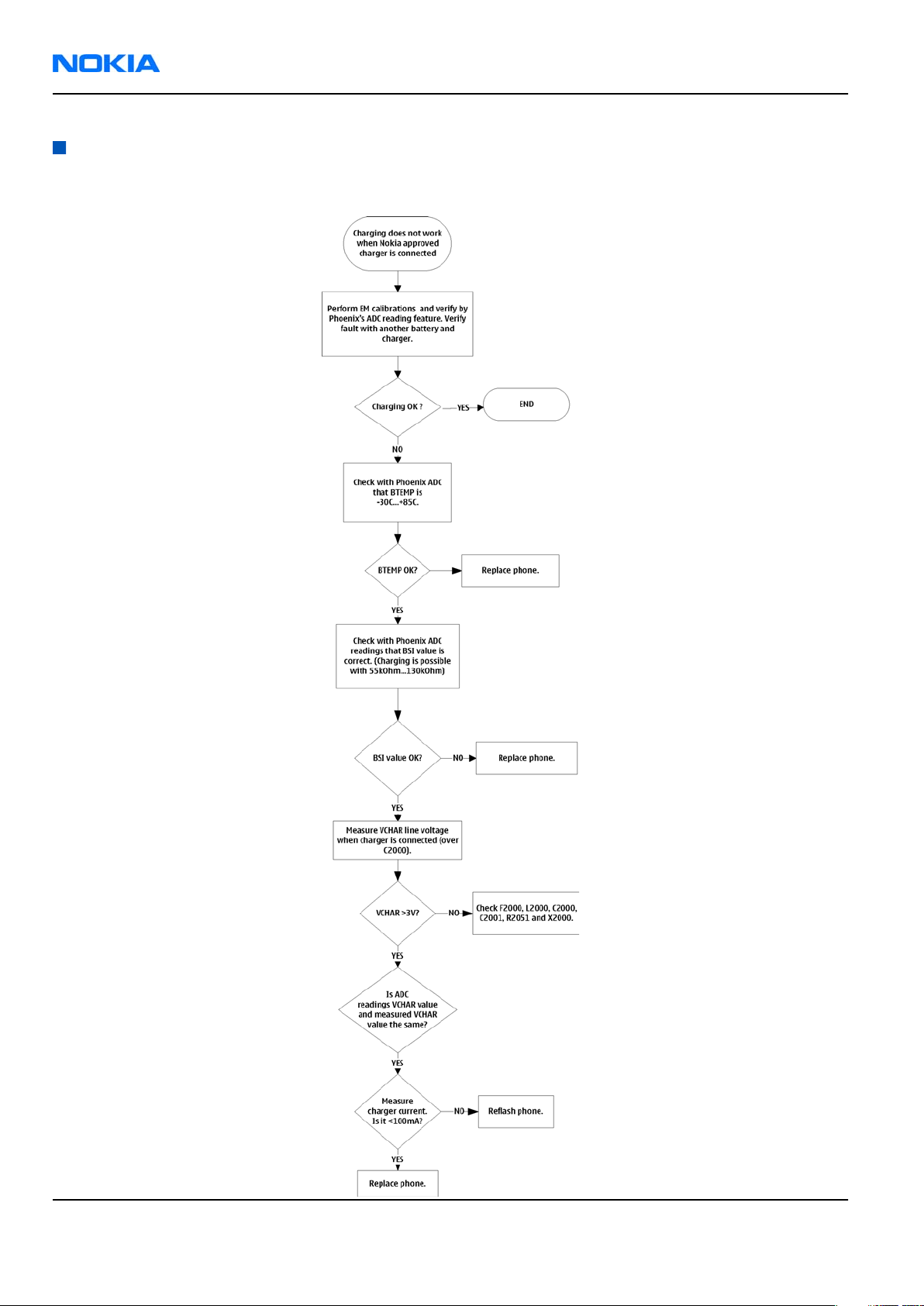
Charging troubleshooting
Troubleshooting flow
Page 6 –12 COMPANY CONFIDENTIAL Issue 1
Copyright © 2006 Nokia. All rights reserved.
Page 13
RM-88
BB Troubleshooting and Manual Tuning Guide Nokia Customer Care
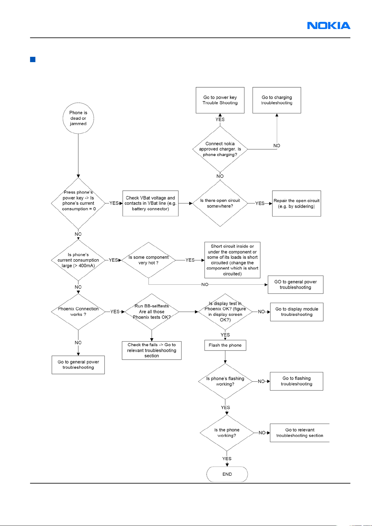
Dead or jammed troubleshooting
Troubleshooting flow
Issue 1 COMPANY CONFIDENTIAL Page 6 –13
Copyright © 2006 Nokia. All rights reserved.
Page 14
RM-88
Nokia Customer Care BB Troubleshooting and Manual Tuning Guide
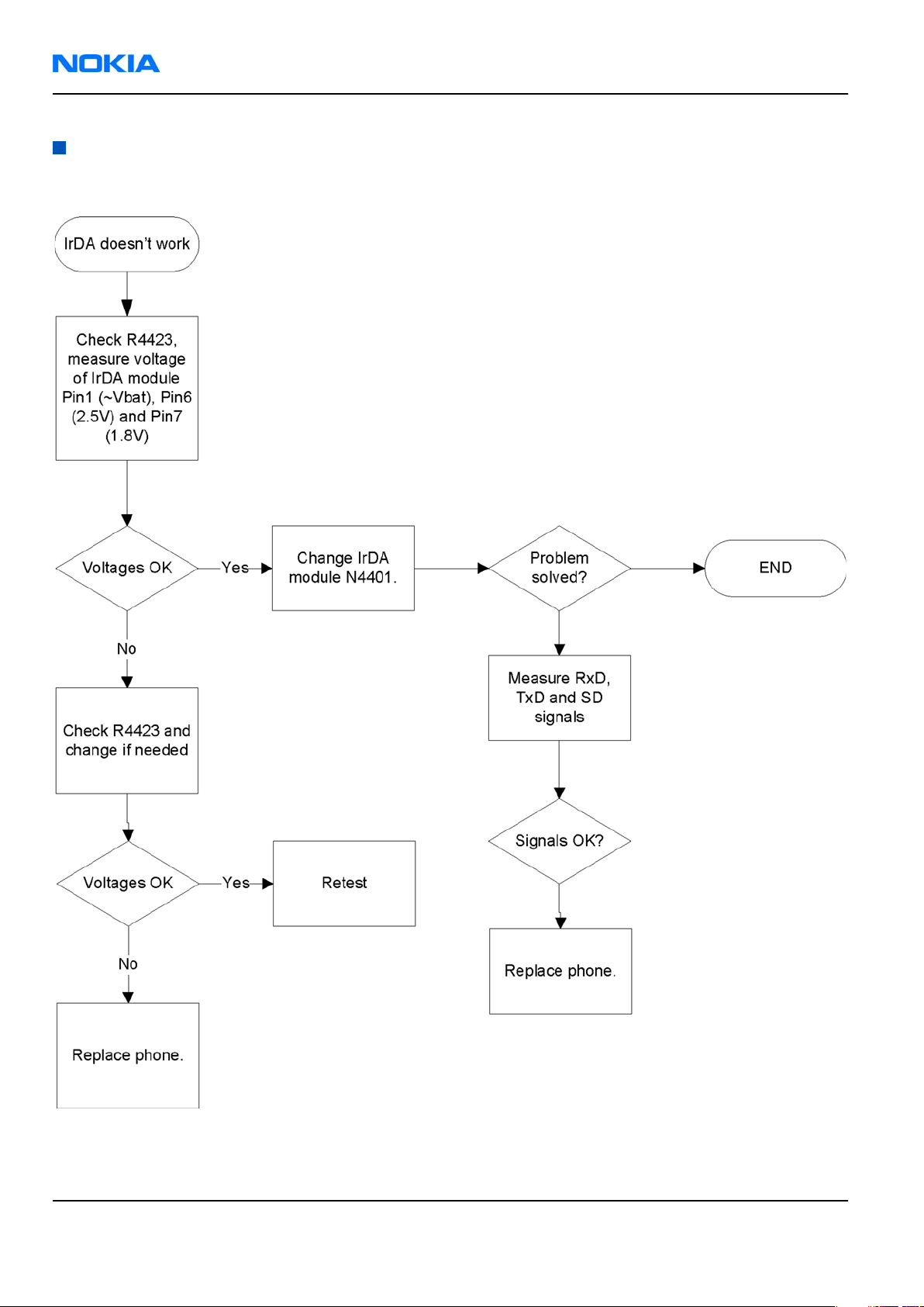
IrDA troubleshooting
Troubleshooting flow
Page 6 –14 COMPANY CONFIDENTIAL Issue 1
Copyright © 2006 Nokia. All rights reserved.
Page 15

RM-88
BB Troubleshooting and Manual Tuning Guide Nokia Customer Care
Vibra troubleshooting
Troubleshooting flow
Issue 1 COMPANY CONFIDENTIAL Page 6 –15
Copyright © 2006 Nokia. All rights reserved.
Page 16

RM-88
Nokia Customer Care BB Troubleshooting and Manual Tuning Guide
MiniSD troubleshooting
Troubleshooting flow
Page 6 –16 COMPANY CONFIDENTIAL Issue 1
Copyright © 2006 Nokia. All rights reserved.
Page 17

RM-88
BB Troubleshooting and Manual Tuning Guide Nokia Customer Care
SIM troubleshooting
Troubleshooting flow
Issue 1 COMPANY CONFIDENTIAL Page 6 –17
Copyright © 2006 Nokia. All rights reserved.
Page 18

RM-88
Nokia Customer Care BB Troubleshooting and Manual Tuning Guide
Display module troubleshooting
General instructions for display troubleshooting
The first step is to verify with a working display that the fault is not on the display module itself. The display
module cannot be repaired.
The second step is to check that the cellular engine is working normally. This can be done by connecting the
phone to a docking station and starting Phoenix service software. With the help of Phoenix read the phone
information to check that also the application engine is functioning normally (you should be able to read the
APE ID).
After these checks proceed to the display troubleshooting flowcharts. Use the Display Test tool in Phoenix to
find the detailed fault mode.
Operating modes of the display
The display is in a normal mode when the phone is in active use.
The display is in a partial idle mode when the phone is in the screen saver mode.
The operating modes of the display can be controlled with the help of Phoenix.
Table 9 Display module troubleshooting cases
Display blank There is no image on the display. The display looks
the same when the phone is on as it does when the
phone is off. The backlight can be on in some cases.
Image on the display not correct Image on the display can be corrupted or a part of
the image can be missing. If a part of the image is
missing, change the display module. If the image is
otherwise corrupted, follow the appropriate
troubleshooting diagram.
Backlight dim or not working at all Backlight LED components are inside the display
module. Backlight failure can also be in the
connector or in the backlight power source in the
main engine of the phone. Backlight is also
controlled automatically by the ambient light
sensor.
This means that in case the display is working
(image OK), but the backlight is not, follow the
Display and Keyboard Backlight troubleshooting.
Visual defects (pixel) Pixel defects can be checked by controlling the
display with Phoenix. Use both colours, black and
white, on a full screen.
The display may have some random pixel defects
that are acceptable for this type of display. The
criteria when pixel defects are regarded as a display
failure, resulting in a replacement of the display, are
presented the following table.
Page 6 –18 COMPANY CONFIDENTIAL Issue 1
Copyright © 2006 Nokia. All rights reserved.
Page 19

RM-88
BB Troubleshooting and Manual Tuning Guide Nokia Customer Care
Table 10 Pixel defects
Item White dot defect Black dot
defect
1 Defect
counts
R G B White
Dot
1 1
Total
1 1 1 1
2 Combine
d defect
counts
Not allowed.
Two single dot defects that are within 5 mm of each other should
be interpreted as combined dot defect.
Note: Blinking pixels are not allowed in normal operating temperatures and light conditions.
Total
Issue 1 COMPANY CONFIDENTIAL Page 6 –19
Copyright © 2006 Nokia. All rights reserved.
Page 20

RM-88
Nokia Customer Care BB Troubleshooting and Manual Tuning Guide
Display fault troubleshooting
Troubleshooting flow
Page 6 –20 COMPANY CONFIDENTIAL Issue 1
Copyright © 2006 Nokia. All rights reserved.
Page 21

RM-88
BB Troubleshooting and Manual Tuning Guide Nokia Customer Care
Display and keyboard backlight troubleshooting
Context
The device has one LED driver that provides current for the display backlight.
The brightness of the display is adjusted by the Ambient Light Sensor (ALS).
You can enable/disable ALS with the help of Phoenix service software.
Display brightness can be adjusted manually, if ALS is disabled. If the ambient light sensor is enabled, it
adjusts the display brightness automatically.
Issue 1 COMPANY CONFIDENTIAL Page 6 –21
Copyright © 2006 Nokia. All rights reserved.
Page 22

RM-88
Nokia Customer Care BB Troubleshooting and Manual Tuning Guide
Troubleshooting flow
Page 6 –22 COMPANY CONFIDENTIAL Issue 1
Copyright © 2006 Nokia. All rights reserved.
Page 23

RM-88
BB Troubleshooting and Manual Tuning Guide Nokia Customer Care
Related information
• Display fault troubleshooting (page 6–20)
• LED driver troubleshooting (page 6–28)
• ALS troubleshooting (page 6–25)
Issue 1 COMPANY CONFIDENTIAL Page 6 –23
Copyright © 2006 Nokia. All rights reserved.
Page 24

RM-88
Nokia Customer Care BB Troubleshooting and Manual Tuning Guide
EL backlight fault troubleshooting
Troubleshooting flow
Page 6 –24 COMPANY CONFIDENTIAL Issue 1
Copyright © 2006 Nokia. All rights reserved.
Page 25

RM-88
BB Troubleshooting and Manual Tuning Guide Nokia Customer Care
ALS troubleshooting
Context
• If a phototransistor is broken, replace it with a typical phototransistor.
• After replacing the phototransistor or if calibration values are lost for some other reason, ALS re-tuning is
required.
• Before starting the ALS calibration procedure, perform the 'Pull-up resistor calibration' in dark lighting
conditions, and write the measured 'correction' value to the phone. After this ALS calibration procedure
is performed, and the default co-efficient value '1' is written to the phone.
• Make sure that you have completed Display and keypad backlight troubleshooting first before
starting ALS troubleshooting.
Here are some hints for ALS troubleshooting; the following troubleshooting diagram refers to these:
•
Phoenix
office environment 100-2000 lx. The luminance value depends strongly on the light source and the angle
of the phone, so these values are only a rough guideline.
• LED driver control voltage measurement points can be found from the LED driver troubleshooting
section. When backlight brightness is set to 100%, both GENOUT signals are low, and enable PWM is 100%.
•
Phoenix
calibration is done first. See the following procedure.
LED control tool also shows you luminance. The correct luminance in darkness is <20 lx, and in
has an ambient light sensor calibration tool for changing calibration values. The pull-up resistor
Issue 1 COMPANY CONFIDENTIAL Page 6 –25
Copyright © 2006 Nokia. All rights reserved.
Page 26

RM-88
Nokia Customer Care BB Troubleshooting and Manual Tuning Guide
Steps
1. Cover the light guide (upper part of the A-Cover).
2. Start
3. Choose File→Scan Product.
4. Choose Tuning→Ambient Light Sensor Calibration.
Phoenix
.
5. In the
6. In the
Figure 36
Pull Up Resistor Calibration
Ambient Light Sensor Calibration
Ambient Light Sensor Calibration
window
pane, click Start, and Write.
pane, check the Use default values only check box, and click
Write.
7. To end the calibration, click Close.
Page 6 –26 COMPANY CONFIDENTIAL Issue 1
Copyright © 2006 Nokia. All rights reserved.
Page 27

RM-88
BB Troubleshooting and Manual Tuning Guide Nokia Customer Care
Troubleshooting flow
Issue 1 COMPANY CONFIDENTIAL Page 6 –27
Copyright © 2006 Nokia. All rights reserved.
Page 28

RM-88
Nokia Customer Care BB Troubleshooting and Manual Tuning Guide
LED driver troubleshooting
Troubleshooting flow
Page 6 –28 COMPANY CONFIDENTIAL Issue 1
Copyright © 2006 Nokia. All rights reserved.
Page 29

RM-88
BB Troubleshooting and Manual Tuning Guide Nokia Customer Care
Bluetooth troubleshooting
Introduction to Bluetooth troubleshooting
There are two main Bluetooth problems that can occur:
Problem Description
Detachment of the BT antenna. This would most likely happen if the device has
been dropped repeatedly to the ground. It could
cause the BT antenna to become loose or partially
detached from the PWB. (see next page for details
about BT antenna HW and Mechanics)
A malfunction in the BT ASIC, BB ASICs or Phone’s BT
SMD components.
The main issue is to find out if the problem is related to the BT antenna or related to the BT system or the
phone’s BB and then replace/fix the faulty component.
This is unpredictable and could have many causes
i.e. SW or HW related.
Bluetooth settings for Phoenix
Steps
1. Start
2. From the File menu, choose Open Product, and then choose the correct type designator from the
3. Place the phone to a flash adapter in the local mode.
4. Choose Testing→Bluetooth LOCALS .
5. Locate JBT-9’s serial number (12 digits) found in the type label on the back of JBT-9.
6. In the
7. Place the JBT-9 box near (within 10 cm) the BT antenna and click Run BER Test.
Phoenix
Product list.
In addition to JBT-9, also SB-6, JBT-3 and JBT-6 Bluetooth test boxes can be used.
Bluetooth LOCALS
Counterpart BT Device Address line.
This needs to be done only once provided that JBT-9 is not changed.
service software.
window, write the 12-digit serial number on the
Results
Bit Error Rate test result is displayed in the
Issue 1 COMPANY CONFIDENTIAL Page 6 –29
Copyright © 2006 Nokia. All rights reserved.
Bit Error Rate (BER) Tests
pane in the
Bluetooth LOCALS
window.
Page 30

RM-88
Nokia Customer Care BB Troubleshooting and Manual Tuning Guide
Figure 37 BER test result
Bluetooth self tests in Phoenix
Steps
1. Start
2. ChooseFile→Scan Product.
3. Place the phone to a flash adapter.
4. From the Mode drop-down menu, set mode to Local.
5. Choose Testing→Self Tests.
6. In the
Phoenix
Self Tests
• ST_LPRF_IF_TEST
• ST_LPRF_AUDIO_LINES_TEST
• ST_BT_WAKEUP_TEST
service software.
window check the following Bluetooth related tests:
Page 6 –30 COMPANY CONFIDENTIAL Issue 1
Copyright © 2006 Nokia. All rights reserved.
Page 31

RM-88
BB Troubleshooting and Manual Tuning Guide Nokia Customer Care
7. To run the tests, click Start.
Figure 38 Bluetooth self tests in
Phoenix
Issue 1 COMPANY CONFIDENTIAL Page 6 –31
Copyright © 2006 Nokia. All rights reserved.
Page 32

RM-88
Nokia Customer Care BB Troubleshooting and Manual Tuning Guide
Bluetooth BER failure troubleshooting
Troubleshooting flow
Page 6 –32 COMPANY CONFIDENTIAL Issue 1
Copyright © 2006 Nokia. All rights reserved.
Page 33

RM-88
BB Troubleshooting and Manual Tuning Guide Nokia Customer Care
BT audio failure troubleshooting
Troubleshooting flow
Issue 1 COMPANY CONFIDENTIAL Page 6 –33
Copyright © 2006 Nokia. All rights reserved.
Page 34
RM-88
Nokia Customer Care BB Troubleshooting and Manual Tuning Guide
Audio troubleshooting
Audio troubleshooting test instructions
Differential external earpiece and internal earpiece outputs can be measured either with a single-ended or
a differential probe.
When measuring with a single-ended probe each output is measured against the ground.
Internal handsfree output is measured using a current probe, if a special low-pass filter designed for
measuring a digital amplifier is not available. Note also that when using a current probe, the input signal
frequency must be set to 2kHz.
The input signal for each loop test can be either single-ended or differential.
Required equipment
The following equipment is needed for the tests:
• Oscilloscope
• Function generator (sine waveform)
• Current probe (Internal handsfree PWM output measurement)
• Phoenix service software
• Battery voltage 3.7V
Test procedure
Audio can be tested using the Phoenix audio routings option. Three different audio loop paths can be
activated:
• External microphone to Internal earpiece
• External microphone to Internal handsfree speaker
• Internal microphone to External earpiece
Each audio loop sets routing from the specified input to the specified output enabling a quick in-out test.
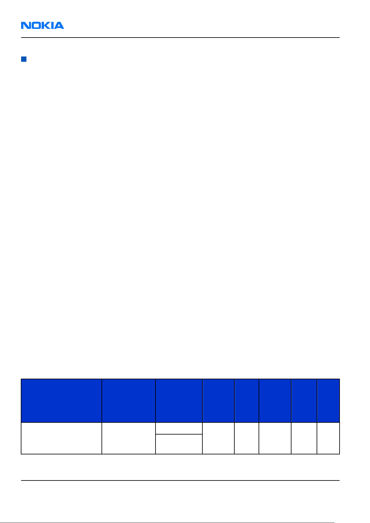
Loop path gains are fixed and they cannot be changed using Phoenix. Correct pins and signals for each test
are presented in the following table.
Phoenix audio loop tests and test results
The results presented in the table apply when no accessory is connected and battery voltage is set to 3.7V.
Earpiece, internal microphone and speaker are in place during measurement. Applying a headset accessory
during measurement causes a significant drop in measured quantities.
The gain values presented in the table apply for a differential output vs. single-ended/differential input.
Loop test Input terminal Output
terminal
Path
gain
[dB]
(fixed)
Input
volta
ge
[mVp-
p]
Differen
tial
output
voltage
[mVp-p]
Outpu
t DC
level
[V]
Outp
ut
curre
nt
[mA]
External Mic to Internal
Earpiece
Page 6 –34 COMPANY CONFIDENTIAL Issue 1
XMICP and GND EarP and GND 35 100 920 1.2 NA
EarN and
GND
Copyright © 2006 Nokia. All rights reserved.
Page 35

RM-88
BB Troubleshooting and Manual Tuning Guide Nokia Customer Care
Loop test Input terminal Output
External Mic to Internal
Handsfree
Internal Mic to External
Earpiece
Measurement data
terminal
Path
gain
[dB]
(fixed)
Input
volta
ge
[mVp-
p]
Differen
tial
output
voltage
[mVp-p]
Outpu
t DC
level
[V]
Outp
ut
curre
nt
[mA]
XMICP and GND B2102 pads 32 100 - 0 80m
A +/10m
A
B2100 (OUT/
GND)
XEARL and
GND
35 100 1360 0 NA
XEARR and
GND
Figure 39 Single-ended output waveform of the Ext_in_HP_out measurement when earpiece is connected.
Figure 40 Differential output waveform of the Ext_in_IHF_out out loop measurement when speaker is connected.
Issue 1 COMPANY CONFIDENTIAL Page 6 –35
Copyright © 2006 Nokia. All rights reserved.
Page 36

RM-88
Nokia Customer Care BB Troubleshooting and Manual Tuning Guide
Figure 41 Single-ended output waveform of the HP_in_Ext_out loop when microphone is connected.
Page 6 –36 COMPANY CONFIDENTIAL Issue 1
Copyright © 2006 Nokia. All rights reserved.
Page 37

RM-88
BB Troubleshooting and Manual Tuning Guide Nokia Customer Care
Internal earpiece troubleshooting
Troubleshooting flow
Issue 1 COMPANY CONFIDENTIAL Page 6 –37
Copyright © 2006 Nokia. All rights reserved.
Page 38
RM-88
Nokia Customer Care BB Troubleshooting and Manual Tuning Guide
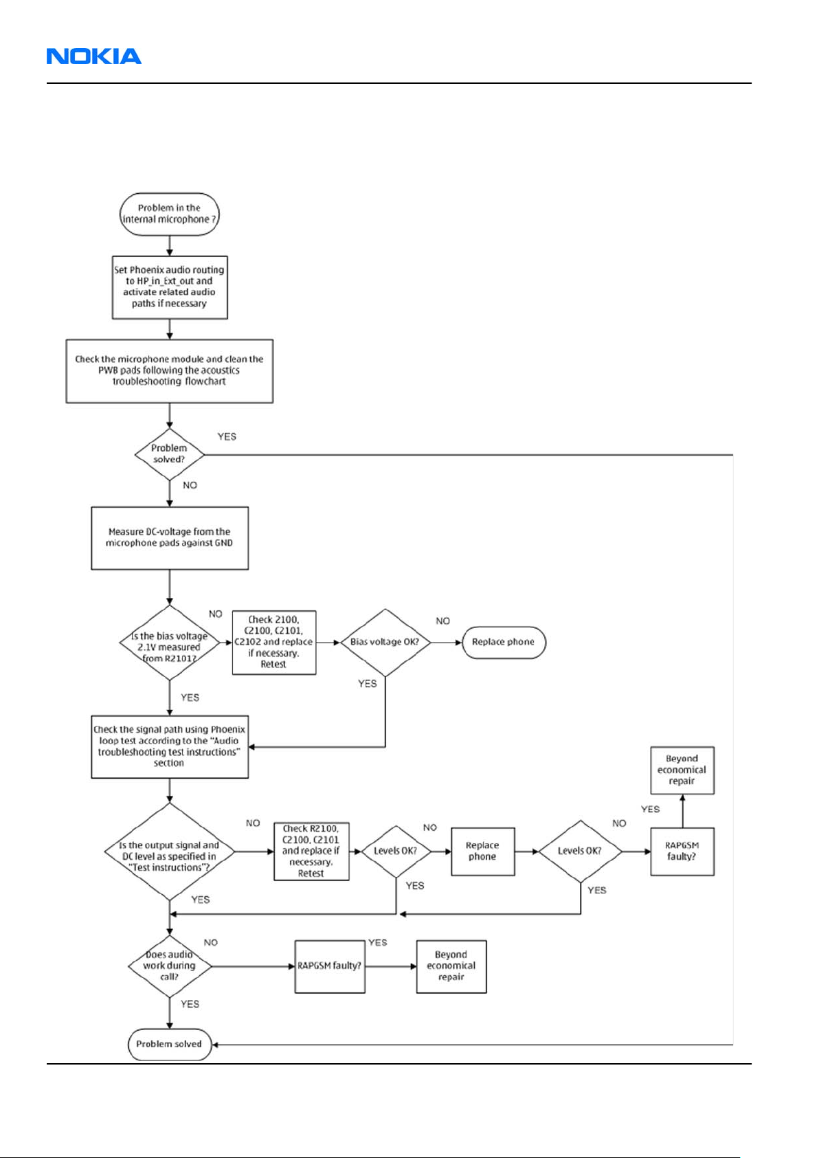
Internal microphone troubleshooting
Troubleshooting flow
Page 6 –38 COMPANY CONFIDENTIAL Issue 1
Copyright © 2006 Nokia. All rights reserved.
Page 39

RM-88
BB Troubleshooting and Manual Tuning Guide Nokia Customer Care
IHF troubleshooting
Troubleshooting flow
Issue 1 COMPANY CONFIDENTIAL Page 6 –39
Copyright © 2006 Nokia. All rights reserved.
Page 40

RM-88
Nokia Customer Care BB Troubleshooting and Manual Tuning Guide
External microphone troubleshooting
Troubleshooting flow
Page 6 –40 COMPANY CONFIDENTIAL Issue 1
Copyright © 2006 Nokia. All rights reserved.
Page 41

RM-88
BB Troubleshooting and Manual Tuning Guide Nokia Customer Care
External earpiece troubleshooting
Troubleshooting flow
Issue 1 COMPANY CONFIDENTIAL Page 6 –41
Copyright © 2006 Nokia. All rights reserved.
Page 42

RM-88
Nokia Customer Care BB Troubleshooting and Manual Tuning Guide
Introduction to acoustics troubleshooting
Acoustics troubleshooting
Acoustics design ensures that the sound is detected correctly with a microphone and properly radiated to
the outside of the device by speaker(s). The acoustics of the phone includes three basic systems: earpiece,
Integrated Hands Free (IHF) and microphone.
The sound reproduced from the earpiece readiates through a single hole on the front cover (A-cover). The
sound reproduced from the IHF speakers radiates from the sound holes on the bottom of the lower block.
The hole of the microphone is located between the upper and the lower block, on the right side..
For a correct functionality of the phone, all sound holes must be always open. When the phone is used, care
must be taken not to close any of those holes with a hand or fingers. The phone should be dry and clean,
and no objects must be located in such a way that they close any of the holes.
Page 6 –42 COMPANY CONFIDENTIAL Issue 1
Copyright © 2006 Nokia. All rights reserved.
Page 43

RM-88
BB Troubleshooting and Manual Tuning Guide Nokia Customer Care
Earpiece troubleshooting
Troubleshooting flow
Issue 1 COMPANY CONFIDENTIAL Page 6 –43
Copyright © 2006 Nokia. All rights reserved.
Page 44

RM-88
Nokia Customer Care BB Troubleshooting and Manual Tuning Guide
Acoustics IHF troubleshooting
Troubleshooting flow
Page 6 –44 COMPANY CONFIDENTIAL Issue 1
Copyright © 2006 Nokia. All rights reserved.
Page 45

RM-88
BB Troubleshooting and Manual Tuning Guide Nokia Customer Care
Microphone troubleshooting
Troubleshooting flow
Issue 1 COMPANY CONFIDENTIAL Page 6 –45
Copyright © 2006 Nokia. All rights reserved.
Page 46

RM-88
Nokia Customer Care BB Troubleshooting and Manual Tuning Guide
Baseband manual tuning guide
Energy management calibration
Prerequisites
Energy Management (EM) calibration is performed to calibrate the setting (gain and offset) of AD converters
in several channels (that is, battery voltage, BSI, battery current) to get an accurate AD conversion result.
Hardware setup:
• An external power supply is needed.
• Supply 12V DC from an external power supply to CU-4 to power up the phone.
• The phone must be connected to a CU-4 control unit with a product-specific flash adapter.
Steps
1. Place the phone to the docking station adapter (CU-4 is connected to the adapter).
2. Start
3. Choose File→ Scan Product.
Phoenix
service software.
4. Choose Tuning→Energy Management Calibration.
5. To show the current values in the phone memory, click Read, and check that communication between
the phone and CU-4 works.
6. Check that the CU-4 used check box is checked.
7. Select the item(s) to be calibrated.
Note: ADC calibration has to be performed before other item(s). However, if all calibrations are
selected at the same time, there is no need to perform the ADC calibration first.
8. Click Calibrate.
The calibration of the selected item(s) is carried out automatically.
The candidates for the new calibration values are shown in the
calibration values seem to be acceptable (please refer to the following "Calibration value limits" table),
click Write to store the new calibration values to the phone permanent memory.
Table 11 Calibration value limits
Parameter Min. Max.
ADC Offset -20 20
ADC Gain 12000 14000
BSI Gain 1100 1300
VBAT Offset 2400 2650
Calculated values
column. If the new
VBAT Gain 19000 23000
IBAT (ICal) Gain 5750 12250
9. Click Read, and confirm that the new calibration values are stored in the phone memory correctly. If the
values are not stored to the phone memory, click Write and/or repeat the procedure again.
10. To end the procedure, close the
Page 6 –46 COMPANY CONFIDENTIAL Issue 1
Energy Management Calibration
Copyright © 2006 Nokia. All rights reserved.
window.
 Loading...