

Page 1

Nokia Customer Care
Service Manual
RM-601; RM-718 (Nokia C6-01; L3&4)
Mobile Terminal
Part No: (Issue 1)
COMPANY CONFIDENTIAL
Copyright © 2010 Nokia. All rights reserved.
Page 2

Amendment Record Sheet
Amendment Record Sheet
Amendment No Date Inserted By Comments
Issue 1 09/2010 MT
RM-601; RM-718
Page ii COMPANY CONFIDENTIAL Issue 1
Copyright © 2010 Nokia. All rights reserved.
Page 3

RM-601; RM-718
Copyright
Copyright
Copyright © 2010 Nokia. All rights reserved.
Reproduction, transfer, distribution or storage of part or all of the contents in this document in any form
without the prior written permission of Nokia is prohibited.
Nokia, Nokia Connecting People, and Nokia X and Y are trademarks or registered trademarks of Nokia
Corporation. Other product and company names mentioned herein may be trademarks or tradenames of
their respective owners.
Nokia operates a policy of continuous development. Nokia reserves the right to make changes and
improvements to any of the products described in this document without prior notice.
Under no circumstances shall Nokia be responsible for any loss of data or income or any special, incidental,
consequential or indirect damages howsoever caused.
The contents of this document are provided "as is". Except as required by applicable law, no warranties of
any kind, either express or implied, including, but not limited to, the implied warranties of merchantability
and fitness for a particular purpose, are made in relation to the accuracy, reliability or contents of this
document. Nokia reserves the right to revise this document or withdraw it at any time without prior notice.
The availability of particular products may vary by region.
IMPORTANT
This document is intended for use by qualified service personnel only.
Issue 1 COMPANY CONFIDENTIAL Page iii
Copyright © 2010 Nokia. All rights reserved.
Page 4

RM-601; RM-718
Warnings and cautions
Warnings and cautions
Warnings
•
IF THE DEVICE CAN BE INSTALLED IN A VEHICLE, CARE MUST BE TAKEN ON INSTALLATION IN VEHICLES FITTED
WITH ELECTRONIC ENGINE MANAGEMENT SYSTEMS AND ANTI-SKID BRAKING SYSTEMS. UNDER CERTAIN FAULT
CONDITIONS, EMITTED RF ENERGY CAN AFFECT THEIR OPERATION. IF NECESSARY, CONSULT THE VEHICLE DEALER/
MANUFACTURER TO DETERMINE THE IMMUNITY OF VEHICLE ELECTRONIC SYSTEMS TO RF ENERGY.
•
THE PRODUCT MUST NOT BE OPERATED IN AREAS LIKELY TO CONTAIN POTENTIALLY EXPLOSIVE ATMOSPHERES,
FOR EXAMPLE, PETROL STATIONS (SERVICE STATIONS), BLASTING AREAS ETC.
•
OPERATION OF ANY RADIO TRANSMITTING EQUIPMENT, INCLUDING CELLULAR TELEPHONES, MAY INTERFERE
WITH THE FUNCTIONALITY OF INADEQUATELY PROTECTED MEDICAL DEVICES. CONSULT A PHYSICIAN OR THE
MANUFACTURER OF THE MEDICAL DEVICE IF YOU HAVE ANY QUESTIONS. OTHER ELECTRONIC EQUIPMENT MAY
ALSO BE SUBJECT TO INTERFERENCE.
•
BEFORE MAKING ANY TEST CONNECTIONS, MAKE SURE YOU HAVE SWITCHED OFF ALL EQUIPMENT.
Cautions
•
Servicing and alignment must be undertaken by qualified personnel only.
•
Ensure all work is carried out at an anti-static workstation and that an anti-static wrist strap is worn.
•
Ensure solder, wire, or foreign matter does not enter the telephone as damage may result.
•
Use only approved components as specified in the parts list.
•
Ensure all components, modules, screws and insulators are correctly re-fitted after servicing and
alignment.
•
Ensure all cables and wires are repositioned correctly.
•
Never test a mobile phone WCDMA transmitter with full Tx power, if there is no possibility to perform the
measurements in a good performance RF-shielded room. Even low power WCDMA transmitters may disturb
nearby WCDMA networks and cause problems to 3G cellular phone communication in a wide area.
•
During testing never activate the GSM or WCDMA transmitter without a proper antenna load, otherwise
GSM or WCDMA PA may be damaged.
Page iv COMPANY CONFIDENTIAL Issue 1
Copyright © 2010 Nokia. All rights reserved.
Page 5

RM-601; RM-718
For your safety
For your safety
QUALIFIED SERVICE
Only qualified personnel may install or repair phone equipment.
ACCESSORIES AND BATTERIES
Use only approved accessories and batteries. Do not connect incompatible products.
CONNECTING TO OTHER DEVICES
When connecting to any other device, read its user’s guide for detailed safety instructions. Do not connect
incompatible products.
Issue 1 COMPANY CONFIDENTIAL Page v
Copyright © 2010 Nokia. All rights reserved.
Page 6

RM-601; RM-718
ESD protection
ESD protection
Nokia requires that service points have sufficient ESD protection (against static electricity) when servicing
the phone.
Any product of which the covers are removed must be handled with ESD protection. The SIM card can be
replaced without ESD protection if the product is otherwise ready for use.
To replace the covers ESD protection must be applied.
All electronic parts of the product are susceptible to ESD. Resistors, too, can be damaged by static electricity
discharge.
All ESD sensitive parts must be packed in metallized protective bags during shipping and handling outside
any ESD Protected Area (EPA).
Every repair action involving opening the product or handling the product components must be done under
ESD protection.
ESD protected spare part packages MUST NOT be opened/closed out of an ESD Protected Area.
For more information and local requirements about ESD protection and ESD Protected Area, contact your local
Nokia After Market Services representative.
Page vi COMPANY CONFIDENTIAL Issue 1
Copyright © 2010 Nokia. All rights reserved.
Page 7

RM-601; RM-718
Care and maintenance
Care and maintenance
This product is of superior design and craftsmanship and should be treated with care. The suggestions below
will help you to fulfil any warranty obligations and to enjoy this product for many years.
•
Keep the phone and all its parts and accessories out of the reach of small children.
•
Keep the phone dry. Precipitation, humidity and all types of liquids or moisture can contain minerals that
will corrode electronic circuits.
•
Do not use or store the phone in dusty, dirty areas. Its moving parts can be damaged.
•
Do not store the phone in hot areas. High temperatures can shorten the life of electronic devices, damage
batteries, and warp or melt certain plastics.
•
Do not store the phone in cold areas. When it warms up (to its normal temperature), moisture can form
inside, which may damage electronic circuit boards.
•
Do not drop, knock or shake the phone. Rough handling can break internal circuit boards.
•
Do not use harsh chemicals, cleaning solvents, or strong detergents to clean the phone.
•
Do not paint the phone. Paint can clog the moving parts and prevent proper operation.
•
Use only the supplied or an approved replacement antenna. Unauthorised antennas, modifications or
attachments could damage the phone and may violate regulations governing radio devices.
All of the above suggestions apply equally to the product, battery, charger or any accessory.
Issue 1 COMPANY CONFIDENTIAL Page vii
Copyright © 2010 Nokia. All rights reserved.
Page 8

RM-601; RM-718
Company policy
Company policy
Our policy is of continuous development; details of all technical modifications will be included with service
bulletins.
While every endeavour has been made to ensure the accuracy of this document, some errors may exist. If
any errors are found by the reader, NOKIA MOBILE PHONES Business Group should be notified in writing/email.
Please state:
•
Title of the Document + Issue Number/Date of publication
•
Latest Amendment Number (if applicable)
•
Page(s) and/or Figure(s) in error
Please send to:
NOKIA CORPORATION
Nokia Mobile Phones Business Group
Nokia Customer Care
PO Box 86
FIN-24101 SALO
Finland
E-mail: Service.Manuals@nokia.com
Page viii COMPANY CONFIDENTIAL Issue 1
Copyright © 2010 Nokia. All rights reserved.
Page 9

RM-601; RM-718
Battery information
Battery information
Note: A new battery's full performance is achieved only after two or three complete charge and
discharge cycles!
The battery can be charged and discharged hundreds of times but it will eventually wear out. When the
operating time (talk-time and standby time) is noticeably shorter than normal, it is time to buy a new battery.
Use only batteries approved by the phone manufacturer and recharge the battery only with the chargers
approved by the manufacturer. Unplug the charger when not in use. Do not leave the battery connected to
a charger for longer than a week, since overcharging may shorten its lifetime. If left unused a fully charged
battery will discharge itself over time.
Temperature extremes can affect the ability of your battery to charge.
For good operation times with Li-Ion batteries, discharge the battery from time to time by leaving the product
switched on until it turns itself off (or by using the battery discharge facility of any approved accessory
available for the product). Do not attempt to discharge the battery by any other means.
Use the battery only for its intended purpose.
Never use any charger or battery which is damaged.
Do not short-circuit the battery. Accidental short-circuiting can occur when a metallic object (coin, clip or
pen) causes direct connection of the + and - terminals of the battery (metal strips on the battery) for example
when you carry a spare battery in your pocket or purse. Short-circuiting the terminals may damage the battery
or the connecting object.
Leaving the battery in hot or cold places, such as in a closed car in summer or winter conditions, will reduce
the capacity and lifetime of the battery. Always try to keep the battery between 15°C and 25°C (59°F and 77°
F). A phone with a hot or cold battery may temporarily not work, even when the battery is fully charged.
Batteries' performance is particularly limited in temperatures well below freezing.
Do not dispose of batteries in a fire!
Dispose of batteries according to local regulations (e.g. recycling). Do not dispose as household waste.
Issue 1 COMPANY CONFIDENTIAL Page ix
Copyright © 2010 Nokia. All rights reserved.
Page 10

RM-601; RM-718
Battery information
(This page left intentionally blank.)
Page x COMPANY CONFIDENTIAL Issue 1
Copyright © 2010 Nokia. All rights reserved.
Page 11

RM-601; RM-718
Nokia C6-01; L3&4 Service Manual Structure
Nokia C6-01; L3&4 Service Manual Structure
1 General Information
2 Service Tools and Service Concepts
3 BB Troubleshooting and Manual Tuning Guide
4 Cellular RF troubleshooting
5 Camera Module Troubleshooting
6 System Module
Glossary
Issue 1 COMPANY CONFIDENTIAL Page xi
Copyright © 2010 Nokia. All rights reserved.
Page 12

RM-601; RM-718
Nokia C6-01; L3&4 Service Manual Structure
(This page left intentionally blank.)
Page xii COMPANY CONFIDENTIAL Issue 1
Copyright © 2010 Nokia. All rights reserved.
Page 13

Nokia Customer Care
1 — General Information
Issue 1 COMPANY CONFIDENTIAL Page 1 – 1
Copyright © 2010 Nokia. All rights reserved.
Page 14

RM-601; RM-718
General Information
(This page left intentionally blank.)
Page 1 – 2 COMPANY CONFIDENTIAL Issue 1
Copyright © 2010 Nokia. All rights reserved.
Page 15

RM-601; RM-718
General Information
Table of Contents
Product selection................................................................................................................................................... 1–5
Product features and sales package.................................................................................................................... 1–6
Product and module list ....................................................................................................................................... 1–9
Mobile enhancements........................................................................................................................................ 1–10
Technical specifications..................................................................................................................................... 1–12
Transceiver general specifications .............................................................................................................. 1–12
Main RF characteristics for GSM850/900/1800/1900 and WCDMA VIII/V/IV/II/I phones........................ 1–12
Main RF characteristics for GSM850/900/1800/1900 and WCDMA VIII/IV/II/I phones............................ 1–14
Battery endurance......................................................................................................................................... 1–15
Environmental conditions ............................................................................................................................ 1–15
List of Tables
Table 1 Audio...................................................................................................................................................... 1–10
Table 2 Car........................................................................................................................................................... 1–11
Table 3 Data ........................................................................................................................................................ 1–11
Table 4 Power..................................................................................................................................................... 1–11
List of Figures
Figure 1 View of RM-601....................................................................................................................................... 1–6
Issue 1 COMPANY CONFIDENTIAL Page 1 – 3
Copyright © 2010 Nokia. All rights reserved.
Page 16

RM-601; RM-718
General Information
(This page left intentionally blank.)
Page 1 – 4 COMPANY CONFIDENTIAL Issue 1
Copyright © 2010 Nokia. All rights reserved.
Page 17

RM-601; RM-718
General Information
Product selection
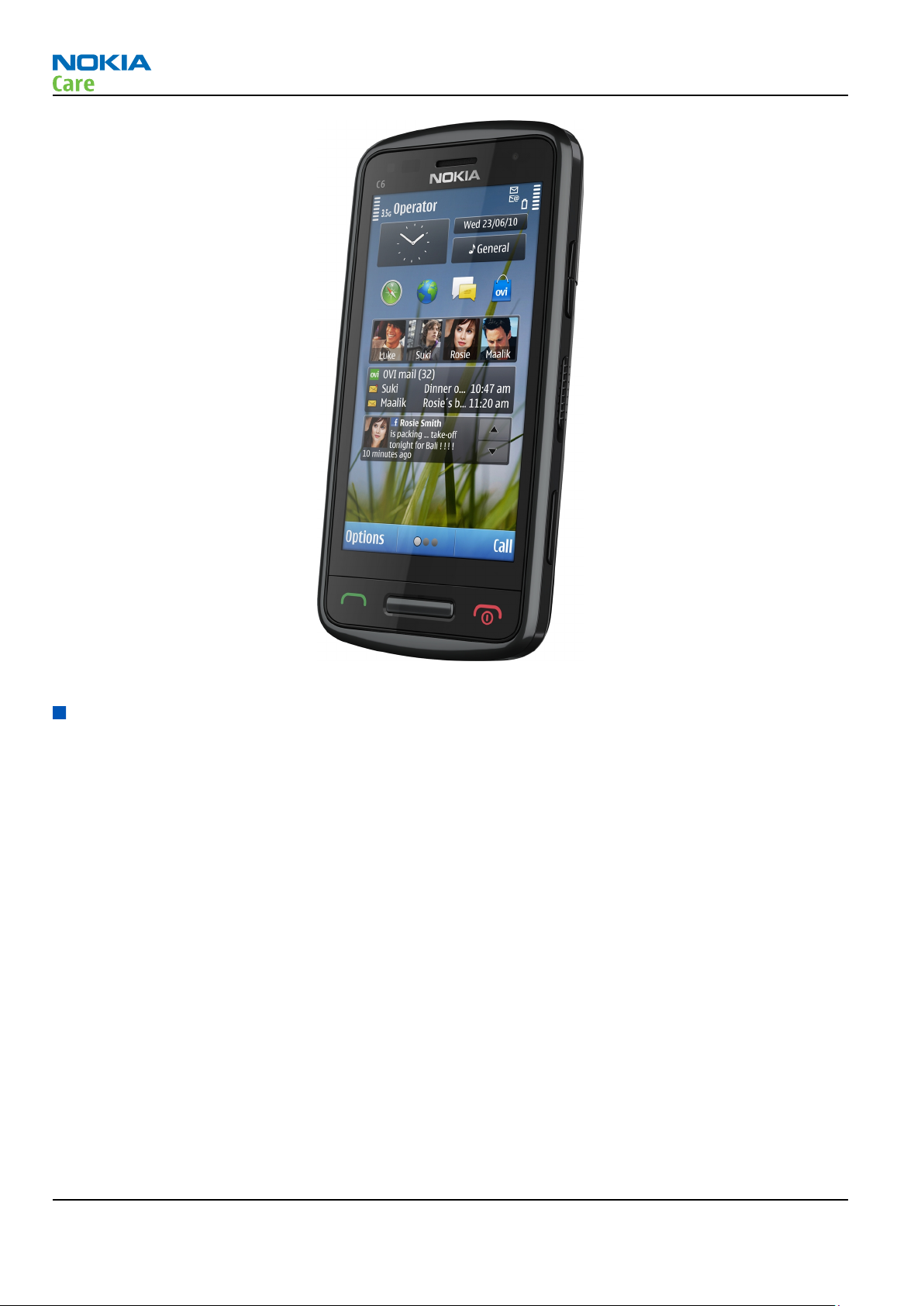
RM-601 and RM-718 are GSM/WCDMA dual-mode handportable monoblock multimedia computers with a
capacitive touch UI, integrated GPS (A-GPS OMA SUPL), WLAN and a TV-out connection. RM-601 supports GSM
850/900/1800/1900 and WCDMA I/II/IV/V/VIII bands, GPRS/EGPRS and WCDMA/HSDPA/HSUPA data bearers.
RM-718 supports GSM 850/900/1800/1900 and WCDMA I/II/IV/VIII bands, GPRS/EGPRS and WCDMA/HSDPA/
HSUPA data bearers.
For WCDMA the maximum bit rate is up to 384 kbit/s for downlink and 384 kbit/s for uplink with simultaneous
CS speech or CS video (max. 64 kbit/s). The device supports HSDPA category 9 with downlink peak data rate
up to 10.2 Mbit/s (in limited use cases), HSUPA belongs to category 5 with uplink peak data rate up to 2.0
Mbit/s (in limited use cases).
In PS/CS mode, the device supports DTM with multi-slot class 11. Class 11 means a maximum of 4 DL and 3
UL timeslots so that the sum of the timeslots does not exceed 5. During DTM the CS timeslot is taken into
account. This means that when DTM mode is active, the maximum DL/UL speed is 177.6/118.4kbit/s with
EGPRS modulation.
In PS only mode, the device supports MSC 33, a maximum of 5 Rx + 4 Tx timeslots (maximum Rx and Tx
timeslot sum 6) resulting in maximum download/upload speed of up to 296/177.6 kbit/s with EGPRS, and
up to 107/64.2 kbit/s with GPRS.
The device has a large AMOLED nHD 3.2” (640 x 360 pixels) colour display (active area 39.6 mm x 70.4 mm)
with 16 million colors. It also has an 8 megapixel EDOF camera, 2 x digital zoom and an integrated dual LED
flash. The device supports two-way video calls with two integrated cameras, one on the front and one on
the back.
The MMS implementation follows the OMA MMS standard release 1.3. The browser is a highly advanced
Internet browser also capable of viewing operator domain XHTML Mobile Profile (MP) content. The device
also supports Bluetooth 2.1 + EDR standard.
The device uses Symbian ^3 for Nokia devices operating system, and supports the full Web Browser for S60,
which brings desktop-like Web browsing experience to mobile devices. It also supports MIDP Java 2.1 ,
providing a good platform for compelling 3rd party applications.
Issue 1 COMPANY CONFIDENTIAL Page 1 – 5
Copyright © 2010 Nokia. All rights reserved.
Page 18
RM-601; RM-718
General Information
Figure 1 View of RM-601
Product features and sales package
Imaging
Main camera:
•
Sensor: 8 Megapixel EDOF (Extended Depth of Field)
•
F number/Aperture: F2.8
•
Digital zoom: 2x
•
Focus range: 50 cm ~ infinity
•
Flash: Integrated dual LED flash
Secondary camera:
•
Sensor: CMOS
•
Still image resolutions: VGA (640 x 480 pixels)
•
Video resolutions: QCIF
Video:
•
Video resolution: HD at 25 fps or VGA at 30 fps
•
Audio recording: AAC (AMR for MMS)
•
Video stabilization
•
Video clip length: max. 90 min
Note that the clip length depends on the available memory and 4GB file size limit
Page 1 – 6 COMPANY CONFIDENTIAL Issue 1
Copyright © 2010 Nokia. All rights reserved.
Page 19

RM-601; RM-718
General Information
•
Video file format: .mp4 (default), .3gp (for MMS)
•
White balance: automatic, sunny, cloudy, incandescent, fluorescent
•
Scene: automatic, low light, night
•
Colour tone: normal, sepia, B&W, vivid
•
Zoom (digital): 3x
•
Video recording indicator
Photo:
•
Still image resolutions: up to 8 megapixel: 3280 x 2464
•
Aspect ratio: 16:9 or 4:3
•
View finder: full screen view finder (6MPix)
•
Still image file format: JPEG/EXIF
•
Auto exposure: center weighted AE
•
Image orientation: automatic
•
Automatic red eye removal
•
Automatic motion blur reduction
•
Face tracking
•
Exposure compensation: +2 ~ -2EV at 0.5 step
•
White balance: automatic, sunny, cloudy, incandescent, fluorescent
•
Scene: automatic, user defined, portrait, landscape, night, night portrait
•
Colour tone: normal, sepia, B&W, vivid
•
Zoom (digital): 2x
Edit
•
On device Photo editor (manual & automatic)
View
•
3.2” nHD (640 x 360 pixels) colour display (active area 39.6 mm x 70.4 mm), up to 16M colors, 16:9 aspect
ratio
•
Digital Ambient Light Sensor (ALS) – used to optimize display/key brightness and power consumption
•
Slideshow from Gallery
Share
•
Nokia XpressShare - share effortlessly from Gallery or after capture via Email, Bluetooth or MMS
•
Direct connection to TV via cable or WLAN (UPnP)
•
Video call and video sharing support. (WCDMA services)
•
Online Album: Image/Video uploading from Gallery
Print
•
Nokia XpressPrint – direct printing via USB (PictBridge), Bluetooth (BPP), and WLAN (UPnP), from memory
card or via online printing
Store
•
2 GB memory card (inbox)
Issue 1 COMPANY CONFIDENTIAL Page 1 – 7
Copyright © 2010 Nokia. All rights reserved.
Page 20

RM-601; RM-718
General Information
•
Nokia XpressTransfer – easy to transfer and organize photos and video between your device and a
compatible PC
•
Nokia Lifeblog (mobile & PC)
Music
•
Digital music player: supports MP3/ AAC/ eAAC/ eAAC+/ WMA/ AMR-NB/ AMR-WB with playlists, equalizer
and album art
•
Synchronise music with Microsoft Windows Media Player 10 & 11
•
One click CD ripping, converting and transferring music to your device using Nokia Music Manager
•
Stereo FM radio (87.5-108 MHz /76-90 MHz) with Visual Radio™ support
•
Bluetooth speakers
•
Integrated handsfree speaker
•
Nokia Music Headset (WH-102), inbox
Media
•
Full-screen video playback to view downloaded, streamed or recorded video clips
•
Supported video formats: MPEG-4 , H.264/AVC, H.263/3GPP, VC-1, Real Video 10, ON2 VP6, Flash video
Productivity
Context management:
•
OMA DRM version 2.0
•
OTA provisioning & over the air SW update (FOTA)
•
Ovi Suite
•
Web Browser (OSS), Java ™ MIDP 2.1, XHTML browsing over TCP/IP
Messaging:
•
E-mail (SMTP, IMAP4, POP3), MMS, SMS, unified editor
•
IM client
Office applications:
•
Viewing of email attachments – .doc, .xls, .ppt, .pdf, .zip
•
Mail for Exchange
PIM:
•
Contacts, calendar, to-do, notes, recorder, calculator, clock, converter
Synchronization:
•
Local/Remote (using SyncML)
•
Data: Calendar, Contacts, To-do, Notes, E-mail
•
PC Applications: Microsoft Outlook (98, 2000, 2002, 2003), Outlook Express, Lotus Organizer (5.0, 6.0),
Lotus Notes (5.0, 6.0)
Call management:
•
Call logs, speed dial, voice dialling (with SIND) and voice commands
•
Nokia Push to Talk (PoC)
Connectivity
•
Integrated GPS (A-GPS OMA SUPL)
Page 1 – 8 COMPANY CONFIDENTIAL Issue 1
Copyright © 2010 Nokia. All rights reserved.
Page 21
RM-601; RM-718
General Information
•
Nokia Maps 3.0, including Friend Finder
•
WLAN - IEEE802.11 g/b/n with UPnP support
•
Micro USB interface with USB 2.0 high speed
•
Bluetooth wireless technology 2.1 + EDR + A2DP
•
MicroSD memory card - support up to 32 GB
•
Nokia 3.5 mm AV connector
•
2.0 mm DC connector
Add-on software framework
•
Symbian ^3 for Nokia devices OS
•
Java: MIDP2.1
•
C++ and Java SDKs
•
Flash Lite 4.0
Additional technical specifications
•
Vibrating alert
•
3GPP Rel 5/6 WCDMA , Rel 4 EGSM compliant
•
Speech codecs supported: AMR, NB AMR, WB AMR, FR, EFR
•
GPRS/EGPRS Class A, Multi slot class 33
•
Dual Transfer Mode (DTM) class A, multi slot class 32
•
WCDMA DL 384 kbit/s, UL 384 kbit/s
•
HSDPA up to 10.2 Mbps, HSUPA 2 Mbps
Sales package
•
Transceiver RM-601 or RM-718
•
Charger (AC-15)
•
Battery (BL-5CT)
•
Wired headset (WH-102)
•
Micro USB connectivity cable (CA-179)
•
MicroSD card 2GB (MU-37) with pre-loaded maps and OVI Suite 2.2
•
CD-ROM
•
Quick Guide
Product and module list
Module name Type code Notes
System/RF module PWB 3CQ
UI flex module 3CP
Flash PWB module 3DF
Issue 1 COMPANY CONFIDENTIAL Page 1 – 9
Copyright © 2010 Nokia. All rights reserved.
Page 22
Mobile enhancements
Table 1 Audio
Enhancement Type
Music headsets HS-45
Wired headsets WH-102 (inbox)
WH-103
WH-203
WH-205
WH-500
WH-501
WH-600
WH-601
WH-700
RM-601; RM-718
General Information
WH-701
WH-800
Bluetooth headsets BH-105
BH-106
BH-108
BH-213
BH-215
BH-216
BH-504
BH-505
BH-604
BH-606
BH-607
BH-608
BH-609
BH-804
BH-904
BH-905
Bluetooth speakers MD-7W
Page 1 – 10 COMPANY CONFIDENTIAL Issue 1
Copyright © 2010 Nokia. All rights reserved.
Page 23
RM-601; RM-718
General Information
Table 2 Car
Enhancement Type
Nokia universal mobile holder CR-114
CR-115
Wireless plug-in car handsfree HF-200
HF-310
HF-510
Car kit CK-100
Multimedia car kit CK-300
Display car kit CK-15W
CK-600
Mobile charger DC-4
DC-6
DC-8
DC-9
DC-10
Table 3 Data
Enhancement Type
Connectivity cable CA-101
CA-101D
CA-157
CA-179 (inbox)
Video connectivity cable CA-75U
MicroSD card MU-22, 1 GB
MU-37, 2 GB (inbox)
MU-41, 4 GB
MU-43, 8GB
MU-44, 16GB
MU-45 32GB
Table 4 Power
Enhancement Type
Battery 1050 mAh Li-ion BL-5CT
Travel charger AC-10
AC-15 (inbox)
Issue 1 COMPANY CONFIDENTIAL Page 1 – 11
Copyright © 2010 Nokia. All rights reserved.
Page 24
Enhancement Type
Charger adapter CA-44
Technical specifications
Transceiver general specifications
RM-601; RM-718
General Information
Unit Dimensions (L x W x T)
Transceiver with BL-5CT
1050 mAh Li-ion battery
pack
(mm)
103.8 x 52.5 x 13.9 131 65
Weight (g)
Volume (cm3)
Main RF characteristics for GSM850/900/1800/1900 and WCDMA VIII/V/IV/II/I phones
Parameter Unit
Cellular system GSM850, EGSM900, GSM1800/1900, WCDMA VIII (900), WCDMA V
(850), WCDMA IV (1700/2100), WCDMA II (1900) and WCDMA I
(2100)
Rx frequency band GSM850: 869 - 894MHz
EGSM900: 925 - 960 MHz
GSM1800: 1805 - 1880 MHz
GSM1900: 1930 - 1990 MHz
WCDMA VIII (900): 925 - 960 MHz
WCDMA V (850): 869 - 894 MHz
WCDMA IV (1700/2100): 2110 - 2155 MHz
WCDMA II (1900): 1930 - 1990 MHz
WCDMA I (2100): 2110 - 2170 MHz
Tx frequency band GSM850: 824 - 849 MHz
EGSM900: 880 - 915 MHz
GSM1800: 1710 - 1785 MHz
GSM1900: 1850 - 1910 MHz
WCDMA VIII (900): 880 - 915 MHz
WCDMA V (850): 824 - 849 MHz
WCDMA IV (1700/2100): 1710 - 1755 MHz
WCDMA II (1900): 1850 - 1910 MHz
WCDMA I (2100): 1920 - 1980 MHz
Page 1 – 12 COMPANY CONFIDENTIAL Issue 1
Copyright © 2010 Nokia. All rights reserved.
Page 25
RM-601; RM-718
General Information
Parameter Unit
Output power GSM850: +5 ...+33 dBm/3.2 mW ... 2 W
GSM900: +5 … +33 dBm/3.2 mW … 2 W
GSM1800: +0 … +30 dBm/1.0 mW … 1 W
GSM1900: +0 … +30 dBm/1.0 mW … 1 W
WCDMA VIII (900): -50 ... +24 dBm/0.01 μW ... 251 mW
WCDMA V (850): -50 ... +24 dBm/0.01 μW ... 251 mW
WCDMA IV (1700/2100): -50 ... +24 dBm/0.01 μW ... 251 mW
WCDMA II (1900): -50 ... +21 dBm/0.01 μW ... 126 mW
WCDMA I (2100): -50 ... +24 dBm/0.01 μW ... 251 mW
EDGE output power EDGE850: +5 … +27 dBm/3.2 mW … 501 mW
EDGE900: +5 … +27 dBm/3.2 mW … 501 mW
EDGE1800: +0 … +26 dBm/1.0 mW … 398 mW
EDGE1900:+0 … +26d Bm/1.0 mW … 398 mW
Number of RF channels GSM850: 124
GSM900: 174
GSM1800: 374
GSM1900: 299
WCDMA VIII (900): 152
WCDMA V (850): 108
WCDMA IV (1700/2100): 211
WCDMA II (1900): 289
WCDMA I (2100): 277
Channel spacing 200 kHz (WCDMA II, IV and V 100/200 kHz)
Number of Tx power levels GSM850: 15
GSM900: 15
GSM1800: 16
GSM1900: 16
WCDMA VIII (900): 75
WCDMA V (850): 75
WCDMA IV (1700/2100): 75
WCDMA II (1900): 75
WCDMA I (2100): 75
Issue 1 COMPANY CONFIDENTIAL Page 1 – 13
Copyright © 2010 Nokia. All rights reserved.
Page 26
RM-601; RM-718
General Information
Main RF characteristics for GSM850/900/1800/1900 and WCDMA VIII/IV/II/I phones
Parameter Unit
Cellular system GSM850, EGSM900, GSM1800/1900, WCDMA VIII (900), WCDMA IV
(1700/2100), WCDMA II (1900) and WCDMA I (2100)
Rx frequency band GSM850: 869 - 894MHz
EGSM900: 925 - 960 MHz
GSM1800: 1805 - 1880 MHz
GSM1900: 1930 - 1990 MHz
WCDMA VIII (900): 925 - 960 MHz
WCDMA IV (1700/2100): 2110 - 2155 MHz
WCDMA II (1900): 1930 - 1990 MHz
WCDMA I (2100): 2110 - 2170 MHz
Tx frequency band GSM850: 824 - 849 MHz
EGSM900: 880 - 915 MHz
GSM1800: 1710 - 1785 MHz
GSM1900: 1850 - 1910 MHz
WCDMA VIII (900): 880 - 915 MHz
WCDMA IV (1700/2100): 1710 - 1755 MHz
WCDMA II (1900): 1850 - 1910 MHz
WCDMA I (2100): 1920 - 1980 MHz
Output power GSM850: +5 ...+33 dBm/3.2 mW ... 2 W
GSM900: +5 … +33 dBm/3.2 mW … 2 W
GSM1800: +0 … +30 dBm/1.0 mW … 1 W
GSM1900: +0 … +30 dBm/1.0 mW … 1 W
WCDMA VIII (900): -50 ... +24 dBm/0.01 μW ... 251 mW
WCDMA IV (1700/2100): -50 ... +24 dBm/0.01 μW ... 251 mW
WCDMA II (1900): -50 ... +21 dBm/0.01 μW ... 126 mW
WCDMA I (2100): -50 ... +24 dBm/0.01 μW ... 251 mW
EDGE output power EDGE850: +5 … +27 dBm/3.2 mW … 501 mW
EDGE900: +5 … +27 dBm/3.2 mW … 501 mW
EDGE1800: +0 … +26 dBm/1.0 mW … 398 mW
EDGE1900:+0 … +26d Bm/1.0 mW … 398 mW
Page 1 – 14 COMPANY CONFIDENTIAL Issue 1
Copyright © 2010 Nokia. All rights reserved.
Page 27
RM-601; RM-718
General Information
Parameter Unit
Number of RF channels GSM850: 124
GSM900: 174
GSM1800: 374
GSM1900: 299
WCDMA VIII (900): 152
WCDMA IV (1700/2100): 211
WCDMA II (1900): 289
WCDMA I (2100): 277
Channel spacing 200 kHz (WCDMA II and IV 100/200 kHz)
Number of Tx power levels GSM850: 15
GSM900: 15
GSM1800: 16
GSM1900: 16
WCDMA VIII (900): 75
WCDMA IV (1700/2100): 75
WCDMA II (1900): 75
WCDMA I (2100): 75
Battery endurance
Battery Capacity (mAh) Talk time Stand-by
BL-5CT 1050 Up to 11 h (GSM)
Up to 4 h (WCDMA)
Up to 17 days (GSM)
Up to 19 days (WCDMA)
Environmental conditions
Temperature conditions
Environmental condition Ambient temperature Notes
Normal operation
-15oC...+55oC
Specifications fulfilled
Reduced performance
Intermittent operation
No operation or storage
Issue 1 COMPANY CONFIDENTIAL Page 1 – 15
-25oC...-15oC
+55oC...+70oC
-40oC...-15oC
+70oC...+85 oC
<-40oC...>+85oC
Copyright © 2010 Nokia. All rights reserved.
Operational for shorts periods
only
Operation not guaranteed but an
attempt to operate does not
damage the phone.
No storage or operation: an
attempt may damage the phone.
Page 28
General Information
Environmental condition Ambient temperature Notes
RM-601; RM-718
Charging allowed
Long term storage conditions
-10oC...+60oC
0oC...+85oC
BTemp measurement range for
charging.
Humidity
Relative humidity range is 5...95%.
The HW module is not protected against water. Condensed or splashed water might cause malfunction. Any
submersion of the phone will cause permanent damage. Long-term high humidity, with condensation, will
cause permanent damage because of corrosion.
Vibration
The module should withstand the following vibrations:
•
5 - 10 Hz; +10dB / octave
•
10 - 50 Hz; 5.58 m2 / s3 (0.0558 g2/ Hz)
•
50 - 300 Hz; - 10 dB / octave
ESD strength
Conducted discharge is 8 kV (>10 discharges) and air contact 15 kV ( >10 discharges ).
The standard for electrostatic discharge is IEC 61000-4-2, and this device fulfils level 4 requirements.
RoHS
This device uses RoHS compliant components and lead-free soldering process.
Page 1 – 16 COMPANY CONFIDENTIAL Issue 1
Copyright © 2010 Nokia. All rights reserved.
Page 29

Nokia Customer Care
2 — Service Tools and Service
Concepts
Issue 1 COMPANY CONFIDENTIAL Page 2 – 1
Copyright © 2010 Nokia. All rights reserved.
Page 30

RM-601; RM-718
Service Tools and Service Concepts
(This page left intentionally blank.)
Page 2 – 2 COMPANY CONFIDENTIAL Issue 1
Copyright © 2010 Nokia. All rights reserved.
Page 31

RM-601; RM-718
Service Tools and Service Concepts
Table of Contents
Service tools........................................................................................................................................................... 2–5
Product specific tools....................................................................................................................................... 2–5
MJ-258 .......................................................................................................................................................... 2–5
RJ-233 ........................................................................................................................................................... 2–5
SD-82 ............................................................................................................................................................ 2–6
General tools..................................................................................................................................................... 2–6
AC-35............................................................................................................................................................. 2–6
ACF-8............................................................................................................................................................. 2–6
CU-4............................................................................................................................................................... 2–7
FLS-5 ............................................................................................................................................................. 2–8
FPS-21........................................................................................................................................................... 2–8
JXS-1.............................................................................................................................................................. 2–9
PK-1............................................................................................................................................................... 2–9
SB-6............................................................................................................................................................... 2–9
SB-7............................................................................................................................................................... 2–9
SRT-6.......................................................................................................................................................... 2–10
SS-186........................................................................................................................................................ 2–10
SS-46.......................................................................................................................................................... 2–10
SS-62.......................................................................................................................................................... 2–10
SS-93.......................................................................................................................................................... 2–10
SX-4............................................................................................................................................................ 2–10
Cables.............................................................................................................................................................. 2–11
CA-101 ....................................................................................................................................................... 2–11
CA-158RS ................................................................................................................................................... 2–11
CA-31D ....................................................................................................................................................... 2–11
CA-89DS ..................................................................................................................................................... 2–12
DAU-9S....................................................................................................................................................... 2–12
PCS-1.......................................................................................................................................................... 2–12
XRS-6.......................................................................................................................................................... 2–13
Service concepts ................................................................................................................................................. 2–13
POS (Point of Sale) flash concept ................................................................................................................. 2–13
BB5 USB only – Basic flash concept L3......................................................................................................... 2–14
Level 3 concept for flashing, certificate restore and product code change option 3............................. 2–15
Module jig service concept........................................................................................................................... 2–16
BB/RF tuning concept with module jig ....................................................................................................... 2–17
Bluetooth testing concept with SB-6 .......................................................................................................... 2–18
WLAN functionality testing concept with SB-7 .......................................................................................... 2–19
List of Figures
Figure 2 POS flash concept ................................................................................................................................ 2–13
Figure 3 BB5 USB only – Basic flash concept L3............................................................................................... 2–14
Figure 4 Level 3 concept for flashing, certificate restore and product code change .................................. 2–15
Figure 5 Module jig service concept ................................................................................................................. 2–16
Figure 6 Bluetooth testing concept with SB-6 ................................................................................................ 2–18
Figure 7 WLAN functionality testing concept with SB-7................................................................................. 2–19
Issue 1 COMPANY CONFIDENTIAL Page 2 – 3
Copyright © 2010 Nokia. All rights reserved.
Page 32

RM-601; RM-718
Service Tools and Service Concepts
(This page left intentionally blank.)
Page 2 – 4 COMPANY CONFIDENTIAL Issue 1
Copyright © 2010 Nokia. All rights reserved.
Page 33

RM-601; RM-718
Service Tools and Service Concepts
Service tools
Product specific tools
The table below gives a short overview of service devices that can be used for testing, error analysis, and
repair of product RM-601; RM-718. For the correct use of the service devices, and the best effort of workbench
setup, please refer to various concepts.
MJ-258 Module jig MJ-258 is meant for troubleshooting, testing, tuning and flashing on
the engine level (CU-4 supported).
The jig includes the following features:
•
Provides mechanical interface with the engine module
•
Provides galvanic connection to all needed test pads in module
•
Connector for control unit
•
Access for AV- and USB connectors
•
CA-158RS cable is used together with this jig for RF testing
•
Attenuation values for galvanic RF connection MJ-258
Band Default f/
MHz RX
GSM 850 881.6 0.24 836.6 0.24
GSM 900 942.4 0.25 897.4 0.25
GSM 1800 1842.8 0.37 1747.8 0.35
GSM 1900 1960.0 0.4 1880.0 0.38
WCDMA I 2140.0 0.4 1950.0 0.4
WCDMA II 1960.0 0.4 1880.0 0.38
WCDMA IV 2140.0 0.4 1740.0 0.35
WCDMA V 880.0 0.24 835.0 0.24
WCDMA VIII 942.6 0.25 897.6 0.25
WLAN n/a 2442.0 0.42
FM / Tx n/a
RJ-233 Soldering jig RJ-233 is a soldering jig used for soldering and as a rework jig for the
engine module.
Att. RX Default f/
MHz TX
Att. TX
Issue 1 COMPANY CONFIDENTIAL Page 2 – 5
Copyright © 2010 Nokia. All rights reserved.
Page 34

RM-601; RM-718
Service Tools and Service Concepts
SD-82 Dummy battery SD-82 is designed to support mass SW flashing which enables local
mode while connecting the phone.
General tools
The table below gives a short overview of service devices that can be used for testing, error analysis, and
repair of product RM-601; RM-718. For the correct use of the service devices, and the best effort of workbench
setup, please refer to various concepts.
AC-35 Power supply Universal power supply for FPS-21; included in the FPS-21 sales
package.
Input 100V…230V 50Hz…60Hz, output voltage of 12 V and output
current up to 3 A.
ACF-8 Universal power
supply
The ACF-8 universal power supply is used to power FLS-5.
Page 2 – 6 COMPANY CONFIDENTIAL Issue 1
Copyright © 2010 Nokia. All rights reserved.
Page 35

RM-601; RM-718
Service Tools and Service Concepts
CU-4 Control unit CU-4 is a general service tool used with a module jig and/or a flash
adapter. It requires an external 12 V power supply.
The unit has the following features:
•
software controlled via USB
•
EM calibration function
•
Forwards FBUS/Flashbus traffic to/from terminal
•
Forwards USB traffic to/from terminal
•
software controlled BSI values
•
regulated VBATT voltage
•
2 x USB2.0 connector (Hub)
•
FBUS and USB connections supported
When using CU-4, note the special order of connecting cables and
other service equipment:
Instructions
1 Connect a service tool (jig, flash adapter) to CU-4.
2 Connect CU-4 to your PC with a USB cable.
3 Connect supply voltage (12 V)
4 Connect an FBUS cable (if necessary).
5 Start Phoenix service software.
Note: Phoenix enables CU-4 regulators via USB when it is
started.
Reconnecting the power supply requires a Phoenix restart.
Issue 1 COMPANY CONFIDENTIAL Page 2 – 7
Copyright © 2010 Nokia. All rights reserved.
Page 36

RM-601; RM-718
Service Tools and Service Concepts
FLS-5 Flash device FLS-5 is a dongle and flash device incorporated into one package,
developed specifically for POS use.
Note: FLS-5 can be used as an alternative to PK-1.
FPS-21 Flash prommer
FPS-21 sales package:
•
FPS-21 prommer
•
AC-35 power supply
•
CA-31D USB cable
FPS-21 interfaces:
Front
•
Service cable connector
Provides Flashbus, USB and VBAT connections to a mobile device.
•
SmartCard socket
A SmartCard is needed to allow DCT-4 generation mobile device
programming.
Rear
•
DC power input
For connecting the external power supply (AC-35).
•
Two USB A type ports (USB1/USB3)
Can be used, for example, for connecting external storage memory
devices or mobile devices
•
One USB B type device connector (USB2)
For connecting a PC.
•
Phone connector
Service cable connection for connecting Flashbus/FLA.
•
Ethernet RJ45 type socket (LAN)
For connecting the FPS-21 to LAN.
Inside
•
Four SD card memory slots
For internal storage memory.
Note: In order to access the SD memory card slots inside
FPS-21, the prommer needs to be opened by removing the
front panel, rear panel and heatsink from the prommer body.
Page 2 – 8 COMPANY CONFIDENTIAL Issue 1
Copyright © 2010 Nokia. All rights reserved.
Page 37

RM-601; RM-718
Service Tools and Service Concepts
JXS-1 RF shield box Because the WCDMA network disturbs the RX side testing of the WCDMA
phone and the Tx signal of the WCDMA phone can severely disturb the
WCDMA network, a shield box is needed in all testing, tuning and fault
finding which requires WCDMA RF signal.
The shield box is not an active device, it contains only passive filtering
components for RF attenuation.
PK-1 Software protection
key
PK-1 is a hardware protection key with a USB interface. It has the same
functionality as the PKD-1 series dongle.
PK-1 is meant for use with a PC that does not have a series interface.
To use this USB dongle for security service functions please register
the dongle in the same way as the PKD-1 series dongle.
SB-6 Bluetooth test and
interface box (sales
package)
The SB-6 test box is a generic service device used to perform Bluetooth
bit error rate (BER) testing, and establishing cordless FBUS connection
via Bluetooth. An ACP-8x charger is needed for BER testing and an
AXS-4 cable in case of cordless interface usage testing .
Sales package includes:
•
SB-6 test box
•
Installation and warranty information
SB-7 WLAN test box WLAN test requires defined position for the device.
Issue 1 COMPANY CONFIDENTIAL Page 2 – 9
Copyright © 2010 Nokia. All rights reserved.
Page 38

RM-601; RM-718
Service Tools and Service Concepts
SRT-6 Opening tool SRT-6 is used to open phone covers.
Note: The SRT-6 is included in the Nokia Standard Toolkit.
SS-186 Camera removal tool The camera removal tool SS-186 is used to remove/attach the camera
module from/to the camera socket of the phone PWB.
SS-46 Interface adapter SS-46 acts as an interface adapter between the flash adapter and
FPS-21.
SS-62 Generic flash adapter
base for BB5
•
generic base for flash adapters and couplers
•
SS-62 equipped with a clip interlock system
•
provides standardised interface towards Control Unit
•
multiplexing between USB and FBUS media, controlled by VUSB
SS-93 Opening tool SS-93 is used for opening JAE connectors.
Note: The SS-93 is included in Nokia Standard Toolkit.
SX-4 Smart card SX-4 is a BB5 security device used to protect critical features in tuning
and testing.
SX-4 is also needed together with FPS-21 when DCT-4 phones are
flashed.
Page 2 – 10 COMPANY CONFIDENTIAL Issue 1
Copyright © 2010 Nokia. All rights reserved.
Page 39

RM-601; RM-718
Service Tools and Service Concepts
Cables
The table below gives a short overview of service devices that can be used for testing, error analysis, and
repair of product RM-601; RM-718. For the correct use of the service devices, and the best effort of workbench
setup, please refer to various concepts.
CA-101 Micro USB cable The CA-101 is a USB-to-microUSB data cable that allows connections
between the PC and the phone.
CA-158RS RF tuning cable Product-specific adapter cable for RF tuning.
CA-31D USB cable The CA-31D USB cable is used to connect FPS-21 to a PC. It is included
in the FPS-21 sales package.
Issue 1 COMPANY CONFIDENTIAL Page 2 – 11
Copyright © 2010 Nokia. All rights reserved.
Page 40

RM-601; RM-718
Service Tools and Service Concepts
CA-89DS Cable Provides VBAT and Flashbus connections to mobile device
programming adapters.
DAU-9S MBUS cable The MBUS cable DAU-9S has a modular connector and is used, for
example, between the PC's serial port and module jigs, flash adapters
or docking station adapters.
Note: Docking station adapters valid for DCT4 products.
PCS-1 Power cable The PCS-1 power cable (DC) is used with a docking station, a module
jig or a control unit to supply a controlled voltage.
Page 2 – 12 COMPANY CONFIDENTIAL Issue 1
Copyright © 2010 Nokia. All rights reserved.
Page 41

RM-601; RM-718
Service Tools and Service Concepts
Service concepts
POS (Point of Sale) flash concept
XRS-6 RF cable The RF cable is used to connect, for example, a module repair jig to
the RF measurement equipment.
SMA to N-Connector approximately 610 mm.
Attenuation for:
•
GSM850/900: 0.3+-0.1 dB
•
GSM1800/1900: 0.5+-0.1 dB
•
WCDMA/WLAN: 0.6+-0.1dB
Figure 2 POS flash concept
Type Description
Product specific tools
SD-82 Care dummy battery
Issue 1 COMPANY CONFIDENTIAL Page 2 – 13
Copyright © 2010 Nokia. All rights reserved.
Page 42

Type Description
Other tools
FLS-5 POS flash dongle
PC with Phoenix service software
Cables
CA-101 Micro USB cable
BB5 USB only – Basic flash concept L3
RM-601; RM-718
Service Tools and Service Concepts
Figure 3 BB5 USB only – Basic flash concept L3
Type Description
Product specific devices
SD-82 Care dummy battery
Other devices
PK-1 SW security device
Page 2 – 14 COMPANY CONFIDENTIAL Issue 1
Copyright © 2010 Nokia. All rights reserved.
Page 43

RM-601; RM-718
Service Tools and Service Concepts
Type Description
PC with Phoenix service software
Cables
CA-101 Micro USB cable
Level 3 concept for flashing, certificate restore and product code change option 3
Figure 4 Level 3 concept for flashing, certificate restore and product code change
Type Description
Product specific devices
SD-82 Care dummy battery
Other devices
CA-146C Power conversion adapter
FPS-21 Flash prommer box
AC-35 Power supply
PK-1 SW security device
SX-4 Smart card (for DCT-4 generation mobile device programming)
PC with Phoenix service software
Issue 1 COMPANY CONFIDENTIAL Page 2 – 15
Copyright © 2010 Nokia. All rights reserved.
Page 44

Type Description
Cables
CA-101 Micro USB cable
CA-89DS Service cable
Module jig service concept
RM-601; RM-718
Service Tools and Service Concepts
Figure 5 Module jig service concept
Type Description
Phone specific devices
MJ-258 Module jig
Other devices
CU-4 Control unit
FPS-21 Flash prommer box
PK-1 SW security device
SX-4 Smart card
PC with VPOS and Phoenix service software
Measurement equipment
Cables
CA-89DS Service cable
PCS-1 DC power cable
Page 2 – 16 COMPANY CONFIDENTIAL Issue 1
Copyright © 2010 Nokia. All rights reserved.
Page 45

RM-601; RM-718
Service Tools and Service Concepts
Type Description
XRS-6 RF cable
USB cable
GPIB control cable
BB/RF tuning concept with module jig
Type Description
Product specific tools
MJ-258 Module jig
Other tools
CU-4 Control unit
PK-1 SW security device
SX-4 Smart card
PC with Phoenix service software
Smart card reader
Cables
DAU-9S MBUS cable
PCS-1 Power cable
XRS-6 RF cable
Issue 1 COMPANY CONFIDENTIAL Page 2 – 17
Copyright © 2010 Nokia. All rights reserved.
Page 46

Type Description
USB cable
Bluetooth testing concept with SB-6
RM-601; RM-718
Service Tools and Service Concepts
Figure 6 Bluetooth testing concept with SB-6
Type Description
Product specific devices
BL-5CT Battery
Other devices
PK-1 SW security device
SX-4 Smart card
SB-6 Bluetooth test and interface box
Smart card reader
PC with Phoenix service software
Cables
Page 2 – 18 COMPANY CONFIDENTIAL Issue 1
Copyright © 2010 Nokia. All rights reserved.
Page 47

RM-601; RM-718
Service Tools and Service Concepts
Type Description
CA-101 Micro USB cable
WLAN functionality testing concept with SB-7
Figure 7 WLAN functionality testing concept with SB-7
Type Description
Product specific tools
BL-5CT Battery
Other tools
SX-4 Smart card
PK-1 SW Security device
Note: PK-1 can be used instead of PKD-1.
Cables
CA-101 Micro USB cable
Issue 1 COMPANY CONFIDENTIAL Page 2 – 19
Copyright © 2010 Nokia. All rights reserved.
Page 48

RM-601; RM-718
Service Tools and Service Concepts
(This page left intentionally blank.)
Page 2 – 20 COMPANY CONFIDENTIAL Issue 1
Copyright © 2010 Nokia. All rights reserved.
Page 49

Nokia Customer Care
3 — BB Troubleshooting and
Manual Tuning Guide
Issue 1 COMPANY CONFIDENTIAL Page 3 – 1
Copyright © 2010 Nokia. All rights reserved.
Page 50

RM-601; RM-718
BB Troubleshooting and Manual Tuning Guide
(This page left intentionally blank.)
Page 3 – 2 COMPANY CONFIDENTIAL Issue 1
Copyright © 2010 Nokia. All rights reserved.
Page 51

RM-601; RM-718
BB Troubleshooting and Manual Tuning Guide
Table of Contents
Baseband main troubleshooting......................................................................................................................... 3–5
Power and charging troubleshooting................................................................................................................. 3–9
Backup battery troubleshooting..................................................................................................................... 3–9
Battery current measuring fault troubleshooting ........................................................................................ 3–9
General power checking troubleshooting .................................................................................................. 3–10
Dead or jammed device troubleshooting................................................................................................... 3–12
Dynamo charging troubleshooting ............................................................................................................. 3–13
Clocking troubleshooting ............................................................................................................................. 3–14
USB charging troubleshooting..................................................................................................................... 3–15
Interface troubleshooting ................................................................................................................................. 3–16
USB flashing fault troubleshooting ............................................................................................................. 3–16
USB data interface troubleshooting............................................................................................................ 3–17
SIM card troubleshooting ............................................................................................................................. 3–17
MicroSD card troubleshooting...................................................................................................................... 3–19
IVE troubleshooting ........................................................................................................................................... 3–21
Introduction to IVE troubleshooting........................................................................................................... 3–21
IVE troubleshooting ...................................................................................................................................... 3–22
TV out troubleshooting...................................................................................................................................... 3–23
Introduction to SDTV troubleshooting........................................................................................................ 3–23
SDTV out troubleshooting ............................................................................................................................ 3–24
Display module troubleshooting ...................................................................................................................... 3–26
General instructions for display troubleshooting...................................................................................... 3–26
Introduction to display troubleshooting.................................................................................................... 3–28
Display fault troubleshooting ...................................................................................................................... 3–29
Touch panel troubleshooting....................................................................................................................... 3–29
Illumination troubleshooting ...................................................................................................................... 3–31
Charging illumination troubleshooting................................................................................................. 3–31
Keyboard backlight troubleshooting ..................................................................................................... 3–32
Keyboard troubleshooting ................................................................................................................................ 3–33
Keyboard troubleshooting ........................................................................................................................... 3–33
Sensors troubleshooting ................................................................................................................................... 3–34
Accelerometer troubleshooting................................................................................................................... 3–34
Magnetometer troubleshooting.................................................................................................................. 3–35
Proximity sensor troubleshooting............................................................................................................... 3–37
ALS technical description and troubleshooting ......................................................................................... 3–37
Ambient Light Sensor (ALS)..................................................................................................................... 3–37
ALS functionality check............................................................................................................................ 3–38
Re-tuning ALS ........................................................................................................................................... 3–39
ALS troubleshooting ................................................................................................................................ 3–40
Audio troubleshooting....................................................................................................................................... 3–41
Audio troubleshooting test instructions..................................................................................................... 3–41
External earpiece troubleshooting.............................................................................................................. 3–43
External microphone troubleshooting........................................................................................................ 3–43
Internal earpiece troubleshooting .............................................................................................................. 3–45
Internal handsfree (IHF) troubleshooting................................................................................................... 3–46
Internal microphone troubleshooting........................................................................................................ 3–47
Acoustics troubleshooting............................................................................................................................ 3–48
Introduction to acoustics troubleshooting ........................................................................................... 3–48
Earpiece troubleshooting........................................................................................................................ 3–49
IHF troubleshooting................................................................................................................................. 3–49
Issue 1 COMPANY CONFIDENTIAL Page 3 – 3
Copyright © 2010 Nokia. All rights reserved.
Page 52

RM-601; RM-718
BB Troubleshooting and Manual Tuning Guide
Microphone troubleshooting .................................................................................................................. 3–51
Vibra troubleshooting................................................................................................................................... 3–52
Connectivity module troubleshooting ............................................................................................................. 3–52
Introduction to connectivity module troubleshooting ............................................................................. 3–52
Bluetooth/FM radio and WLAN troubleshooting........................................................................................ 3–55
Introduction to Bluetooth/FM radio troubleshooting.......................................................................... 3–55
Introduction to WLAN troubleshooting ................................................................................................. 3–57
Bluetooth and FM radio self tests in Phoenix............................................................................................. 3–58
WLAN self test in Phoenix............................................................................................................................. 3–59
Bluetooth BER test in Phoenix ..................................................................................................................... 3–59
FMRX radio receiver testing.......................................................................................................................... 3–60
WLAN TX and RX testing in Phoenix ............................................................................................................ 3–61
WLAN TX BiP testing procedure in Phoenix................................................................................................ 3–61
WLAN TX BiP testing procedure in Testing and Tuning Tool .................................................................... 3–63
Bluetooth troubleshooting .......................................................................................................................... 3–66
FMRX receiver troubleshooting.................................................................................................................... 3–66
WLAN troubleshooting ................................................................................................................................. 3–67
GPS troubleshooting .......................................................................................................................................... 3–68
Introduction to GPS troubleshooting.......................................................................................................... 3–68
GPS settings for Phoenix............................................................................................................................... 3–69
Quick Test window................................................................................................................................... 3–69
GPS control................................................................................................................................................ 3–70
GPS failure troubleshooting......................................................................................................................... 3–71
GPS basic checks troubleshooting ............................................................................................................... 3–72
Baseband manual tuning guide........................................................................................................................ 3–74
Certificate restoring for BB5 products......................................................................................................... 3–74
Energy management calibration................................................................................................................. 3–79
List of Tables
Table 5 Display module troubleshooting cases............................................................................................... 3–26
Table 6 Pixel defects .......................................................................................................................................... 3–27
Table 7 Defects table.......................................................................................................................................... 3–27
Table 8 Calibration value limits ........................................................................................................................ 3–79
List of Figures
Figure 8 Expected Crystal clock input to BCM2727B on Oscilloscope ............................................................ 3–22
Figure 9 Expected SDTV CVBS PAL signal on Oscilloscope............................................................................... 3–25
Figure 10 Expected SDTV CVBS NTSC signal on Oscilloscope........................................................................... 3–26
Figure 11 Ambient Light Sensor ....................................................................................................................... 3–38
Figure 12 Hardware connections between BB and BOB1.0M-b..................................................................... 3–53
Figure 13 Bluetooth/WLAN/GPS antenna......................................................................................................... 3–54
Figure 14 Connectivity module's component layout, bottom side ............................................................... 3–54
Figure 15 Connectivity module's test points, top side ................................................................................... 3–55
Figure 16 Bluetooth and FM radio self tests in Phoenix................................................................................. 3–59
Figure 17 Bluetooth BER test in Phoenix ......................................................................................................... 3–60
Figure 18 GPS layout and basic test points...................................................................................................... 3–69
Figure 19 GPS Quick Test window .................................................................................................................... 3–70
Figure 20 GPS Control dialogue box ................................................................................................................. 3–71
Page 3 – 4 COMPANY CONFIDENTIAL Issue 1
Copyright © 2010 Nokia. All rights reserved.
Page 53

RM-601; RM-718
BB Troubleshooting and Manual Tuning Guide
Baseband main troubleshooting
Context
Always start the troubleshooting procedure by running the Phoenix self tests. If a test fails, please follow the
diagrams below. If the phone is dead and you cannot perform the self tests, go to
troubleshooting
.
Dead or jammed device
Issue 1 COMPANY CONFIDENTIAL Page 3 – 5
Copyright © 2010 Nokia. All rights reserved.
Page 54

Troubleshooting flow - Page 1 of 3
RM-601; RM-718
BB Troubleshooting and Manual Tuning Guide
Page 3 – 6 COMPANY CONFIDENTIAL Issue 1
Copyright © 2010 Nokia. All rights reserved.
Page 55

RM-601; RM-718
BB Troubleshooting and Manual Tuning Guide
Troubleshooting flow - Page 2 of 3
Issue 1 COMPANY CONFIDENTIAL Page 3 – 7
Copyright © 2010 Nokia. All rights reserved.
Page 56

Troubleshooting flow - Page 3 of 3
RM-601; RM-718
BB Troubleshooting and Manual Tuning Guide
Page 3 – 8 COMPANY CONFIDENTIAL Issue 1
Copyright © 2010 Nokia. All rights reserved.
Page 57

RM-601; RM-718
BB Troubleshooting and Manual Tuning Guide
Power and charging troubleshooting
Backup battery troubleshooting
Troubleshooting flow
Issue 1 COMPANY CONFIDENTIAL Page 3 – 9
Copyright © 2010 Nokia. All rights reserved.
Page 58

Battery current measuring fault troubleshooting
Troubleshooting flow
RM-601; RM-718
BB Troubleshooting and Manual Tuning Guide
Page 3 – 10 COMPANY CONFIDENTIAL Issue 1
Copyright © 2010 Nokia. All rights reserved.
Page 59

RM-601; RM-718
BB Troubleshooting and Manual Tuning Guide
General power checking troubleshooting
Troubleshooting flow
Issue 1 COMPANY CONFIDENTIAL Page 3 – 11
Copyright © 2010 Nokia. All rights reserved.
Page 60

Dead or jammed device troubleshooting
Troubleshooting flow
RM-601; RM-718
BB Troubleshooting and Manual Tuning Guide
Page 3 – 12 COMPANY CONFIDENTIAL Issue 1
Copyright © 2010 Nokia. All rights reserved.
Page 61

RM-601; RM-718
BB Troubleshooting and Manual Tuning Guide
Dynamo charging troubleshooting
Troubleshooting flow
Issue 1 COMPANY CONFIDENTIAL Page 3 – 13
Copyright © 2010 Nokia. All rights reserved.
Page 62

Clocking troubleshooting
Troubleshooting flow
RM-601; RM-718
BB Troubleshooting and Manual Tuning Guide
Page 3 – 14 COMPANY CONFIDENTIAL Issue 1
Copyright © 2010 Nokia. All rights reserved.
Page 63

RM-601; RM-718
BB Troubleshooting and Manual Tuning Guide
USB charging troubleshooting
Troubleshooting flow
Issue 1 COMPANY CONFIDENTIAL Page 3 – 15
Copyright © 2010 Nokia. All rights reserved.
Page 64

Interface troubleshooting
USB flashing fault troubleshooting
Troubleshooting flow
RM-601; RM-718
BB Troubleshooting and Manual Tuning Guide
Page 3 – 16 COMPANY CONFIDENTIAL Issue 1
Copyright © 2010 Nokia. All rights reserved.
Page 65

RM-601; RM-718
BB Troubleshooting and Manual Tuning Guide
USB data interface troubleshooting
Troubleshooting flow
Issue 1 COMPANY CONFIDENTIAL Page 3 – 17
Copyright © 2010 Nokia. All rights reserved.
Page 66

SIM card troubleshooting
Troubleshooting flow
RM-601; RM-718
BB Troubleshooting and Manual Tuning Guide
Page 3 – 18 COMPANY CONFIDENTIAL Issue 1
Copyright © 2010 Nokia. All rights reserved.
Page 67

RM-601; RM-718
BB Troubleshooting and Manual Tuning Guide
Issue 1 COMPANY CONFIDENTIAL Page 3 – 19
Copyright © 2010 Nokia. All rights reserved.
Page 68

MicroSD card troubleshooting
Troubleshooting flow
RM-601; RM-718
BB Troubleshooting and Manual Tuning Guide
Page 3 – 20 COMPANY CONFIDENTIAL Issue 1
Copyright © 2010 Nokia. All rights reserved.
Page 69

RM-601; RM-718
BB Troubleshooting and Manual Tuning Guide
IVE troubleshooting
Introduction to IVE troubleshooting
The IVE engine is a next generation imaging and video engine based on BCM2727B. The BCM2727B acts as
imaging, video, display, and HDTV and SDTV hardware accelerator.
The following references on the PWB help in the effective debugging and troubleshooting of IVE.
Sr. No Reference Description
1 B1400 19.2MHz Crystal
2 D1400 IVE/BCM2727B IC
The following test points on the PWB help in the effective debugging and troubleshooting.
Sr. No Signal name Measuring point Description
1 VIVE_2V5_FILT C1419/C1417 2.5V supply to BCM2727B
2 VIVE_2V8_FILT C1414 2.8V supply to BCM2727B
3 VIVE_1V8_FILT L1402/C1450 1.8V supply to BCM2727B
4 VBAT L1403/C1466 VBAT supply to BCM2727B
5 RUN J1425 Enable signal to IVE. This needs to be
High for IVE to be Up.
6 XIN C1448 19.2MHz clock to IVE
Issue 1 COMPANY CONFIDENTIAL Page 3 – 21
Copyright © 2010 Nokia. All rights reserved.
Page 70

IVE troubleshooting
Troubleshooting flow
RM-601; RM-718
BB Troubleshooting and Manual Tuning Guide
Page 3 – 22 COMPANY CONFIDENTIAL Issue 1
Copyright © 2010 Nokia. All rights reserved.
Page 71

RM-601; RM-718
BB Troubleshooting and Manual Tuning Guide
Figure 8 Expected Crystal clock input to BCM2727B on Oscilloscope
TV out troubleshooting
Introduction to SDTV troubleshooting
SDTV
The phone has SDTV capability. The phone can be connected to an analog TV through a TV Out cable.
The following references on the PWB help in the effective debugging and troubleshooting of SDTV Out.
Sr. No Reference Description
1 R1419 DAC termination resistor. Resistor value 15 OHMS.
2 D1400 BCM2727B IC
3 N2001 Analog switch
4 L2001 Ferrite bead on the CVBS signal
5 X2000 AV connector
The following test points on the PWB help in the effective debugging and troubleshooting.
Sr No Signal name Measuring point Description
1 CVBS X2001.2/J2004 SDTV signal
Issue 1 COMPANY CONFIDENTIAL Page 3 – 23
Copyright © 2010 Nokia. All rights reserved.
Page 72

SDTV out troubleshooting
Troubleshooting flow
RM-601; RM-718
BB Troubleshooting and Manual Tuning Guide
Page 3 – 24 COMPANY CONFIDENTIAL Issue 1
Copyright © 2010 Nokia. All rights reserved.
Page 73

RM-601; RM-718
BB Troubleshooting and Manual Tuning Guide
Figure 9 Expected SDTV CVBS PAL signal on Oscilloscope
Issue 1 COMPANY CONFIDENTIAL Page 3 – 25
Copyright © 2010 Nokia. All rights reserved.
Page 74

RM-601; RM-718
BB Troubleshooting and Manual Tuning Guide
Figure 10 Expected SDTV CVBS NTSC signal on Oscilloscope
Display module troubleshooting
General instructions for display troubleshooting
The first step is to verify with a working display that the fault is not on the display module itself. The display
module cannot be repaired.
Note: Always use the display with the phone's window while checking the display's visual
functionality.
The second step is to check that the engine is working normally. This can be done by connecting the phone
to a docking station and starting Phoenix service software. With the help of Phoenix read the phone
information to check that also the application engine is functioning normally (you should be able to read the
APE ID).
After these checks proceed to the display troubleshooting flowcharts. Use the Display Test tool in Phoenix to
find the detailed fault mode.
Pixel defects
Table 5 Display module troubleshooting cases
Display blank There is no image on the display. The display looks
the same when the phone is on as it does when the
phone is off.
Page 3 – 26 COMPANY CONFIDENTIAL Issue 1
Copyright © 2010 Nokia. All rights reserved.
Page 75

RM-601; RM-718
BB Troubleshooting and Manual Tuning Guide
Image on the display not correct Image on the display can be corrupted or a part of
the image can be missing. If a part of the image is
missing, change the display module. If the image is
otherwise corrupted, follow the appropriate
troubleshooting diagram.
Visual defects (pixel) Pixel defects can be checked by controlling the
display with Phoenix. Use both colors, black and
white, on a full screen. R, G, B are also helpful.
The display may have some random pixel defects
that are acceptable for this type of display. The
criteria when pixel defects are regarded as a display
failure, resulting in a replacement of the display, are
presented in the following table.
Table 6 Pixel defects
Bright sub-pixels (sometimes called on-pixels or stuck-on) are
characterized by the appearance of bright/colored
pixels in, for example, black full screen picture.
Dark sub-pixels (sometimes called off-pixels, stuck-off, or black
pixels) are characterized by the appearance of dark
pixels in white, red, green, or blue full-screen
picture.
Combined sub-pixel defects are characterized by at least two sub-pixels
defects (bright or dim) being closer than 5 mm to
each other.
Temporal sub-pixels (sometimes called blinking defects) exhibit
temporal variations not related to any steady-state
video input. Temporal sub-pixel defects may be
intermittent, exhibit a sudden change of state, or
be flickering.
Table 7 Defects table
Item Bright dot (sub-
pixel) defect
Dark dot (sub-
pixel) defect
Total
1 Defect counts Not allowed
2 Combined sub-
pixel defect
Not allowed 2 red dim dots or 2
blue dim dots
2 dim dots
3 Temporal sub-
Not allowed
pixel defect
Note: Blinking pixels are not allowed in normal operating temperatures and light conditions.
Issue 1 COMPANY CONFIDENTIAL Page 3 – 27
Copyright © 2010 Nokia. All rights reserved.
Page 76

RM-601; RM-718
BB Troubleshooting and Manual Tuning Guide
Introduction to display troubleshooting
The display module used is based on AM OLED technology and supports display format of 360 columns x 640
rows. The dimension of the display module is 44.30 mm x 79.60 mm x 1.27 mm. The module will interface
to the phone via FPC with a 20 pins board to board connector.
The following references on the PWB help in the effective debugging and troubleshooting of the display.
Sr No Reference Description
1 X1600 Display connector
2 Z1600, Z1601 Common Mode Choke on DSI bus
3 V1600 Series resistor on display Reset and TE line. Reset signal needs
to be High for the display to be Up.
4 D1400 BCM2727B IC
The following test points on the PWB help in the effective debugging and troubleshooting.
Sr. No Signal name Measuring point Description
1 VIO L1600/C1600 1.8V supply to display
2 VBAT L1601/C1602 VBAT supply to display
Page 3 – 28 COMPANY CONFIDENTIAL Issue 1
Copyright © 2010 Nokia. All rights reserved.
Page 77

RM-601; RM-718
BB Troubleshooting and Manual Tuning Guide
Display fault troubleshooting
Troubleshooting flow
Issue 1 COMPANY CONFIDENTIAL Page 3 – 29
Copyright © 2010 Nokia. All rights reserved.
Page 78

Touch panel troubleshooting
Troubleshooting flow
RM-601; RM-718
BB Troubleshooting and Manual Tuning Guide
Page 3 – 30 COMPANY CONFIDENTIAL Issue 1
Copyright © 2010 Nokia. All rights reserved.
Page 79

RM-601; RM-718
BB Troubleshooting and Manual Tuning Guide
Illumination troubleshooting
Charging illumination troubleshooting
Troubleshooting flow
Issue 1 COMPANY CONFIDENTIAL Page 3 – 31
Copyright © 2010 Nokia. All rights reserved.
Page 80

Keyboard backlight troubleshooting
Troubleshooting flow
RM-601; RM-718
BB Troubleshooting and Manual Tuning Guide
Page 3 – 32 COMPANY CONFIDENTIAL Issue 1
Copyright © 2010 Nokia. All rights reserved.
Page 81

RM-601; RM-718
BB Troubleshooting and Manual Tuning Guide
Keyboard troubleshooting
Keyboard troubleshooting
Troubleshooting flow
Issue 1 COMPANY CONFIDENTIAL Page 3 – 33
Copyright © 2010 Nokia. All rights reserved.
Page 82

Sensors troubleshooting
Accelerometer troubleshooting
Troubleshooting flow
RM-601; RM-718
BB Troubleshooting and Manual Tuning Guide
Page 3 – 34 COMPANY CONFIDENTIAL Issue 1
Copyright © 2010 Nokia. All rights reserved.
Page 83

RM-601; RM-718
BB Troubleshooting and Manual Tuning Guide
Magnetometer troubleshooting
Equipment
•
Non-magnetic, horizontal table
•
nearest ferromagnetic part, distance more than 50 cm
•
Traditional needle type compass for reference
•
Rotating platform (sheet of wood or plastic)
•
PC with Phoenix
Preparation of phone
•
Set the rotating platform to the table
•
Set the phone and reference compass to the rotating platform
•
Connect the phone to the PC and start Phoenix
Tests
•
General troubleshooting test
•
Self-test (ST)
•
Azimuth check test
Issue 1 COMPANY CONFIDENTIAL Page 3 – 35
Copyright © 2010 Nokia. All rights reserved.
Page 84

Magnetometer general troubleshooting flow
RM-601; RM-718
BB Troubleshooting and Manual Tuning Guide
Azimuth check
•
Search magnetically quiet place for the test table
•
No disturbing elements near the table, such as motors, coils, electric currents or similar
•
Calibrate the phone as described in the user manual
•
The indicator must be GREEN
Page 3 – 36 COMPANY CONFIDENTIAL Issue 1
Copyright © 2010 Nokia. All rights reserved.
Page 85

RM-601; RM-718
BB Troubleshooting and Manual Tuning Guide
•
Rotate the platform manually one round on the horizontal table with steps of approximately 15° degrees
•
The reference angle direction value from the reference compass = REF(angle)
•
Read the phone value = ACT(angle)
•
Calculate for every step (24 steps)
•
Result(angle) = REF(angle) - ACT(angle)
•
The result is the real angle difference of angles in a 360° degrees continuous round
•
Criteria:
•
If the Result(angle) value < 15° degrees GO, otherwise NOGO
Proximity sensor troubleshooting
Troubleshooting flow
ALS technical description and troubleshooting
Ambient Light Sensor (ALS)
Pupumon V1100 is a digital Ambient Light Sensor (ALS) which is connected to RAPU via I2C_2 bus. It does not
have an interrupt signal as in Augumon ALS. Power supply voltage is provided from VAUX2 output of EM ASIC.
ALS is used in backlight control system to measure the amount of ambient light reaching display surface so
that it is possible to adjust the display (and keypad) brightness in order to achieve good user experience.
This also helps in saving power.
Issue 1 COMPANY CONFIDENTIAL Page 3 – 37
Copyright © 2010 Nokia. All rights reserved.
Page 86

RM-601; RM-718
BB Troubleshooting and Manual Tuning Guide
Figure 11 Ambient Light Sensor
ALS functionality check
Steps
1. Connect the phone to Phoenix and set the phone (e.g. on the table) so that the amount of ambient light
seen by ALS is as stabile as possible.
2. Start
3. Choose File -> Scan product .
4. Choose Testing -> Display Test .
5. Open the Lights tab, check Ambient Light Sensor check box, click Read , cover the sensor and click
6. If the component does not give any reading or reading does not change when the sensor is/is not covered,
Phoenix
Read again. When covered, Luminance reading should be less than after clicking Read without covering
the sensor.
replace the part.
.
•
After replacing the ALS, if the calibration values of the new sensor are lost or for some other reason,
ALS re-tuning is required.
•
When doing the ALS calibration procedure, it is required to have a reference phone which includes a
calibrated ALS. ALS re-tuning instructions show why the reference phone is needed.
Page 3 – 38 COMPANY CONFIDENTIAL Issue 1
Copyright © 2010 Nokia. All rights reserved.
Page 87

RM-601; RM-718
BB Troubleshooting and Manual Tuning Guide
Re-tuning ALS
Steps
1. Connect reference phone to Phoenix and set the phone (e.g. on the table) so that the amount of ambient
light seen by ALS is as stable as possible.
2. Start Phoenix.
3. Choose File→Scan Product.
4. Choose Tuning -> Ambient Light Sensor Calibration. You should see the following window:
5. Read AD-count values for Channel 0 and Channel 1 by click Read button and write them down.
6. Repeat 1-5 for the phone to be calibrated and make sure the phone to be calibrated is located in the
same place as reference phone was when luminance reading was taken.
7. Calculate co-efficient from reference phone and phone to be calibrated AD-count values by division: Co-
efficient = AD-count(reference phone) / AD-count(phone to be calibrated), write down the calculated coefficient values.
8. -> Iterate by changing Channel 0 and Channel 1 (reference level) values (remove cross from ‘Use default
values only’). After writing some value to Channel 0 and Channel 1 (reference value), calibrate button
must be pressed. Stop iterating when Co-efficient is equal to Co-efficient calculated in step 7. Note that
decimal numbers should be used in the iteration in order to achieve enough precision (e.g. 200.2455)
9. After having same Co-efficient value in “Co-efficient” textbox as the calculated value, make sure that
ambient light values (read using Testing → Display Test → “Luminance” textbox) are almost the same
in reference phone and calibrated phone. Remember that illuminance readings for reference and
calibrated phones must be done in the same ambient light conditions. If illuminance values differs a lot
(difference max. +- 10%), repeat whole ALS re-tuning procedure.
Issue 1 COMPANY CONFIDENTIAL Page 3 – 39
Copyright © 2010 Nokia. All rights reserved.
Page 88

10. To end the calibration, click Close.
ALS troubleshooting
Troubleshooting flow
RM-601; RM-718
BB Troubleshooting and Manual Tuning Guide
Page 3 – 40 COMPANY CONFIDENTIAL Issue 1
Copyright © 2010 Nokia. All rights reserved.
Page 89

RM-601; RM-718
BB Troubleshooting and Manual Tuning Guide
Audio troubleshooting
Audio troubleshooting test instructions
Single-ended external earpiece and differential internal earpiece outputs can be measured either with a
single-ended or a differential probe.
When measuring with a single-ended probe each output is measured against the ground.
Internal handsfree output is measured using a current probe, if a special low-pass filter designed for
measuring a digital amplifier is not available. Note also that when using a current probe, the input signal
frequency must be set to 2 kHz.
The input signal for each loop test can be either single-ended or differential. Exception to this is a digital
microphone which needs input signal from an external sound source (laptop speaker) to playback, eg. 1 kHz
sine wave from 5 cm distance.
Required equipment
The following equipment is needed for the tests:
•
Oscilloscope
•
Function generator (sine waveform)
•
Current probe (Internal handsfree DPMA output measurement)
•
Phoenix service software
•
Battery voltage 3.7V
•
Sound source (laptop speaker or B&K type 4231 calibrator)
Test procedure
Audio can be tested using the Phoenix audio routings option. Three different audio loop paths can be
activated:
•
External headset mic to earpiece
•
External headset mic to IHF mono
•
Internal digital microphone to headset
Each audio loop sets routing from the specified input to the specified output enabling a quick in-out test.
Loop path gains are fixed and they cannot be changed using Phoenix. Correct pins and signals for each test
are presented in the following table.
Phoenix audio loop tests and test results
The results presented in the table apply when no accessory is connected and battery voltage is set to 3.7V.
Earpiece, internal microphone and speaker are in place during measurement. Applying a headset accessory
during measurement causes a significant drop in measured quantities.
The gain values presented in the table apply for a differential output vs. single-ended/differential input.
Loop test Input
terminal
External
headset
mic to
earpiece
HS_MIC &
GND
Output
terminal
EAR 1 &
GND
EAR 0 &
GND
Path gain
[dB]
(fixed)
0 300 1.35 300
Input
voltage
[mVp-p]
Output DC
level [V]
Output
voltage
[mVp-p]
Issue 1 COMPANY CONFIDENTIAL Page 3 – 41
Copyright © 2010 Nokia. All rights reserved.
Page 90

RM-601; RM-718
BB Troubleshooting and Manual Tuning Guide
Loop test Input
terminal
External
headset
mic to IHF
mono
Internal
digital
micropho
ne to
headset
HS_MIC &
GND
Acoustica
l Input,
1kHz sine
wave
Output
terminal
L4855 &
L4856
L4857 &
L4858
HS_L &
GND
HS_R &
GND
Path gain
[dB]
(fixed)
10 200 630
NA 94 dBSPL 70
Input
voltage
[mVp-p]
Output DC
level [V]
Output
voltage
[mVp-p]
Page 3 – 42 COMPANY CONFIDENTIAL Issue 1
Copyright © 2010 Nokia. All rights reserved.
Page 91

RM-601; RM-718
BB Troubleshooting and Manual Tuning Guide
External earpiece troubleshooting
Troubleshooting flow
Issue 1 COMPANY CONFIDENTIAL Page 3 – 43
Copyright © 2010 Nokia. All rights reserved.
Page 92

External microphone troubleshooting
Troubleshooting flow
RM-601; RM-718
BB Troubleshooting and Manual Tuning Guide
Page 3 – 44 COMPANY CONFIDENTIAL Issue 1
Copyright © 2010 Nokia. All rights reserved.
Page 93

RM-601; RM-718
BB Troubleshooting and Manual Tuning Guide
Internal earpiece troubleshooting
Troubleshooting flow
Issue 1 COMPANY CONFIDENTIAL Page 3 – 45
Copyright © 2010 Nokia. All rights reserved.
Page 94

Internal handsfree (IHF) troubleshooting
Troubleshooting flow
RM-601; RM-718
BB Troubleshooting and Manual Tuning Guide
Page 3 – 46 COMPANY CONFIDENTIAL Issue 1
Copyright © 2010 Nokia. All rights reserved.
Page 95

RM-601; RM-718
BB Troubleshooting and Manual Tuning Guide
Internal microphone troubleshooting
Troubleshooting flow
Issue 1 COMPANY CONFIDENTIAL Page 3 – 47
Copyright © 2010 Nokia. All rights reserved.
Page 96

RM-601; RM-718
BB Troubleshooting and Manual Tuning Guide
Acoustics troubleshooting
Introduction to acoustics troubleshooting
Acoustics design ensures that the sound is detected correctly with a microphone and properly radiated to
the outside of the device by the speaker. The acoustics of the phone include three basic systems: earpiece,
stereo integrated handsfree (IHF) and digital microphone.
The sound reproduced from the earpiece comes through a hole on the front cover (A-cover). The IHF sound
hole is located on the back of the phone, near the camera area. The microphone sound hole is on the bottom
of the phone, beside the USB connector.
For a correct functionality of the phone, all sound holes must be always open. When the phone is used, care
must be taken not to close any of those holes with a hand or fingers. The phone should be dry and clean,
and no objects must be located in such a way that they close any of the holes.
Page 3 – 48 COMPANY CONFIDENTIAL Issue 1
Copyright © 2010 Nokia. All rights reserved.
Page 97

RM-601; RM-718
BB Troubleshooting and Manual Tuning Guide
Earpiece troubleshooting
Troubleshooting flow
Issue 1 COMPANY CONFIDENTIAL Page 3 – 49
Copyright © 2010 Nokia. All rights reserved.
Page 98

IHF troubleshooting
Troubleshooting flow
RM-601; RM-718
BB Troubleshooting and Manual Tuning Guide
Page 3 – 50 COMPANY CONFIDENTIAL Issue 1
Copyright © 2010 Nokia. All rights reserved.
Page 99

RM-601; RM-718
BB Troubleshooting and Manual Tuning Guide
Microphone troubleshooting
Troubleshooting flow
Issue 1 COMPANY CONFIDENTIAL Page 3 – 51
Copyright © 2010 Nokia. All rights reserved.
Page 100

Vibra troubleshooting
Troubleshooting flow
RM-601; RM-718
BB Troubleshooting and Manual Tuning Guide
Connectivity module troubleshooting
Introduction to connectivity module troubleshooting
The BOB1.0M-b module supports WLAN, BT, FMRX and FMTX. From a troubleshooting point of view, WLAN is
tested separately, but BT and FMRX are checked in parallel. This mobile terminal does not include FMTX.
REFOUT_EXT1 single ended 38.4 MHz analog clock from Linko RF is provided to BOB1.0M-b. The clock request
for the reference clock in the BOB1.0M-b module is shared between WLAN and BT blocks. When either system
requires a clock, this signal will be active. The CLK_REQ is connected to ExtSysClkReq pin of RAPU. The SLEEPCLK
Page 3 – 52 COMPANY CONFIDENTIAL Issue 1
Copyright © 2010 Nokia. All rights reserved.
 Loading...