

Page 1

Customer Care Solutions
RH-23 Series Transceivers
Disassembly and Assembly
Instructions
Issue 1 02/2004 Company Confidential Nokia Corporation
Page 2

RH-23 Company confidential
Disassembly and Assembly Instructions CCS Technical Documentation
Table of Contents
Page No
RH-23 Product Selection ...............................................................................................3
Accessories List .............................................................................................................4
Technical Specifications ................................................................................................6
General Specifications of Transceiver RH-23 .............................................................6
Battery endurance ......................................................................................................7
Environmental conditions .........................................................................................7
Transceiver Features ....................................................................................................8
Electrical Characteristics .............................................................................................9
Page 2 Nokia Corporation. Issue 1 02/2004
Page 3
Company confidential RH-23
CCS Technical Documentation Disassembly and Assembly Instructions
Upper Block Disassembly
Note: It is recommended not to open Lower Block and Upper Block at the same time because of the
sensitive Hinge mechanism. When only one Block is opened, Hinge mechanics will stay together.
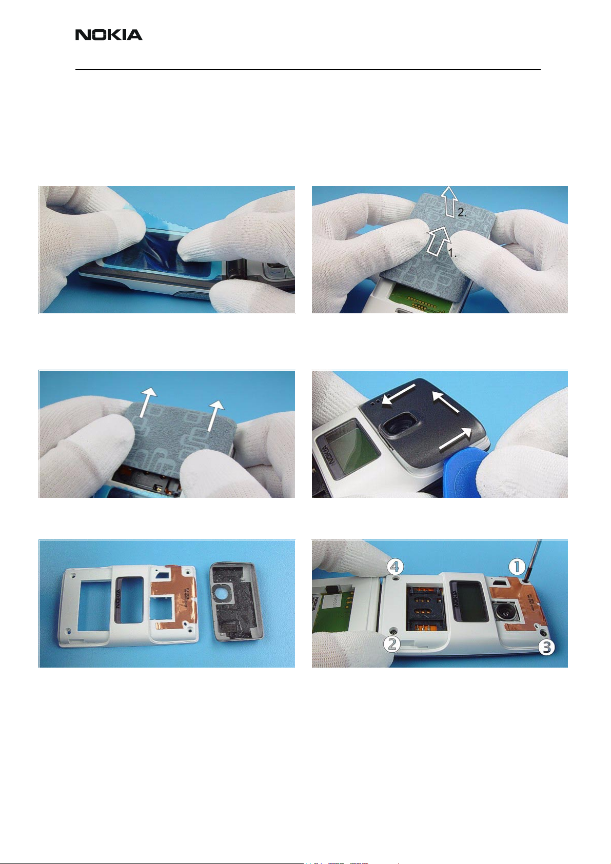
Protect the window with a film to avoid dust and
scratches.
Push the SIM Cover a bit forward and remove it. Antenna Cover is attached with double sided adhesive
Remove the Battery Cover and be sure that the
Battery is removed. Do not disassemble the device
with inserted Battery!
tape. Use SRT-6 as a lever to detach this Cover.
Always use new B-Cover and new Antenna Cover,
because Antenna Radiator will be destroyed during
this removal procedure.
Issue 1 02/2004 Nokia Corporation. Page 3
Unscrew the four Torx Plus® size 6 screws. For assem-
bly, the reverse order and a Torx Plus
torque of 28Ncm have to be used.
Always use new gel screws for assembly!
®
driver with a
Page 4
RH-23 Company confidential
Disassembly and Assembly Instructions CCS Technical Documentation
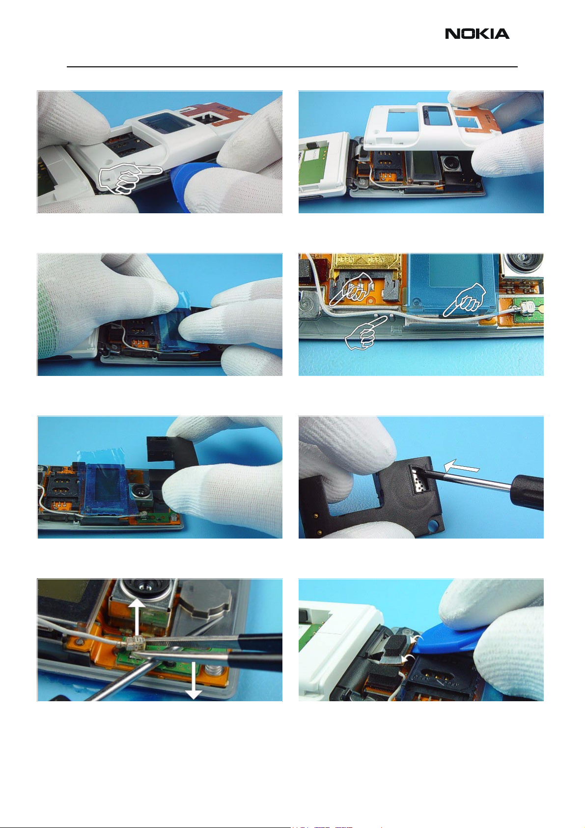
The A-Cover is attached with snaps to the B-Cover Upper.
Release the clip with SRT-6 only.
Protect the LCD with a film. Note the exact guiding of the Coax Cable. This is very
Remove the B-Cover Upper.
important for the assembly procedure.
Remove the IHF Housing. A screwdriver can be used to pull up the IHF-Speaker
form its guidance.
Use tweezers as a lever to open the Coax Connector. Open the connector with SRT-6 carefully.
Page 4 Nokia Corporation. Issue 1 02/2004
Page 5

Company confidential RH-23
CCS Technical Documentation Disassembly and Assembly Instructions
Separate the Lower Block from Upper Block.
Do not close the Hinge Mechanism.
Open the Connector of color LCD carefully. Open the Connector of b/w LCD carefully.
To avoid damage of the Connector move it away when
removing Upper Block Flex Assy.
Bend A-Cover Upper Assy a bit when removing LCD.
Protect the inner side of the Window with a film.
Also protect the color LCD with a film. The black & white LCD is attached with two snaps to the
Upper Frame. Release the snaps by using the SRT-6 and
the LCD drops out.
Issue 1 02/2004 Nokia Corporation. Page 5
Page 6

RH-23 Company confidential
Disassembly and Assembly Instructions CCS Technical Documentation
A slotted screwdriver can be used to remove the
Microphone.
Keep hold of Flex Module as shown in the picture and
use a slotted screwdriver as a lever the to open the
Camera Shield.
When change of the Upper Block Flex Assy is needed,
remove the VGA Camera and assemble it to the new
Upper Block Flex Assy.
Camera Module is attached with four snaps on to
camera connector. Place SRT-10 as shown in the picture
and unlock the snaps on booth sides. Note releasing
order.
Camera Module comes up automatically when snaps are
released.
Page 6 Nokia Corporation. Issue 1 02/2004
Use tweezers to take the Camera Module away.
Page 7

Company confidential RH-23
CCS Technical Documentation Disassembly and Assembly Instructions
Lower Block Disassembly
Note: It is recommended not to open Lower Block and Upper Block at the same time because of the
sensitive Hinge mechanism. When only one Block is opened, Hinge mechanics will stay together.
Protect the window with a film to avoid dust and
scratches.
Remove the Battery cover and be sure that battery
is removed. Do not disassemble the device with
inserted battery!
Also protect the front side of the Upper Block.
Pick up Screw Caps with dental tool. Use always new
Screw Caps when assembling.
Unscrew the four Torx Plus® size 6 screws. For assem-
bly, the reverse order and a Torx Plus
torque of 28Ncm have to be used.
Always use new gel screws for assembly!
®
driver with a
Issue 1 02/2004 Nokia Corporation. Page 7
Hold the Upper Block as shown in the picture and
remove the A-Cover Lower.
Page 8

RH-23 Company confidential
Disassembly and Assembly Instructions CCS Technical Documentation
The Keymat can now be removed. Note that UI-PWB is glued to the Engine Module with a
UI-Adhesive. Do not bend the UI-PWB when detaching it
from Engine Module.
Open the Coax Connector by using tweezers as shown in
the picture.
Take the Engine Module away. To avoid damage to the B-Cover Lower see also video
Open the connector carefully before separating the
Upper Block
clip on Care Point. Remove the Vibra Retainer by using a
slotted screwdriver as a lever.
Page 8 Nokia Corporation. Issue 1 02/2004
Page 9

Company confidential RH-23
CCS Technical Documentation Disassembly and Assembly Instructions
The Vibra Motor can be removed easily. Take care of the
right position when assembling.
Tweezers can be used to remove the DC-Jack. Be careful
not to damage spring contacts.
Take away the Microphone by using the dental tool.
Issue 1 02/2004 Nokia Corporation. Page 9
Page 10

RH-23 Company confidential
Disassembly and Assembly Instructions CCS Technical Documentation
Dome Sheet Assembly
Protect the UI Adhesive. Remove the faulty Domesheet by lifting it up carefully
from UI PWB Module.
Take care about LEDs on the UI PWB Module during
removal of the Domesheet.
Put the new Domesheet onto the Domesheet Assembly
Jig. Mind the guiding pins.
Clean the pads on the PWB Module with a clean cloth if
necessary. Be carefully not damage the components on
the PWB.
Remove the protection film. Tweezers can be used for
retaining the Domesheet.
Page 10 Nokia Corporation. Issue 1 02/2004
Page 11

Company confidential RH-23
CCS Technical Documentation Disassembly and Assembly Instructions
Arrows point to the correct assembly position. Put the UI
PWB Module onto the Domesheet Assembly Jig carefully.
Finally check that the holes of the Domesheet are
centered to the UI PWB module holes. Ensure also, that
there are no bubbles in Domesheet film.
Press on PWB Module after checking that all guiding
pins are positioned correctly.
Remove the protection film from UI PWB Module.
Issue 1 02/2004 Nokia Corporation. Page 11
Page 12

RH-23 Company confidential
Disassembly and Assembly Instructions CCS Technical Documentation
[This page intentionally left blank.]
Page 12 Nokia Corporation. Issue 1 02/2004
 Loading...