

Page 1
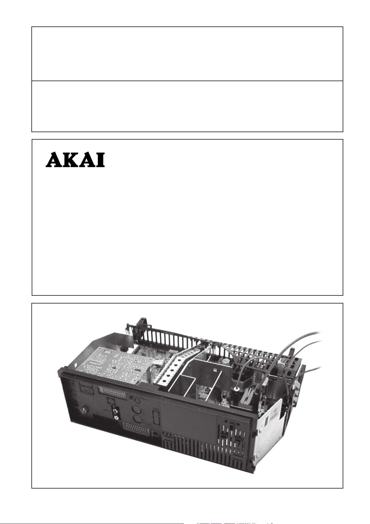
MULTI CONCEPT
57
MX-CHASSIS
(100 Hz, 4:3)
G Service manual
D Service-Manual
S Serviceanvisning
n
TV
1998
F Manuel de service
I Manuale di servizio
TV 2561-TN 100 Hz
TV 2861-TN 100 Hz
TV 2961-TN 100 Hz
TV 2561-T Multi 100 Hz
TV 2861-T Multi 100 Hz
TV 2961-T Multi 100 Hz 3D VGA
63L3-TN 100 Hz
71L3-TN 100 Hz
63L3-T Multi 100 Hz
71L3-T Multi 100 Hz
74F3-TN 100 Hz
74F3-T Multi 100 Hz 3D VGA
6611 7280
Page 2

58
G Contents
Repair instructions .....................................................................................................................................................................1
Technical data .............................................................................................................................................................................2
Block diagrams ...........................................................................................................................................................................3
SCART connector ....................................................................................................................................................................... 6
Operating instructions ...............................................................................................................................................................7
Initialization of NVRAM..............................................................................................................................................................7
Service adjustments...................................................................................................................................................................8
Schematic diagrams ................................................................................................................................................................ 27
Variable components ............................................................................................................................................................... 43
Spare parts................................................................................................................................................................................44
D Inhaltsverzeichnis
Reparatur Anweisung ................................................................................................................................................................1
Technische Daten ....................................................................................................................................................................... 2
Blockschaltbilden ....................................................................................................................................................................... 3
SCART Anschluß ........................................................................................................................................................................6
Bedienungsanleitung ...............................................................................................................................................................11
Initialisierung des NVRAM ...................................................................................................................................................... 11
Service-Einstellungen .............................................................................................................................................................. 12
Schaltpläne ............................................................................................................................................................................... 27
Röhrenabhängige Bauteile ......................................................................................................................................................43
Ersatzteileliste ........................................................................................................................................................................... 44
S Innehåll
Reparationsinstruktioner ........................................................................................................................................................... 1
Tekniska data .............................................................................................................................................................................. 2
Blockschemor ............................................................................................................................................................................. 3
SCART-kontakt ............................................................................................................................................................................ 6
Bruksanvisning .........................................................................................................................................................................15
Initialisering av NVRAM...........................................................................................................................................................15
Serviceinställningar ................................................................................................................................................................. 16
Kopplingsschemor ................................................................................................................................................................... 27
Komponentskillnader ............................................................................................................................................................... 43
Reservdelar ...............................................................................................................................................................................44
F Contenu
Instructions de reparation ......................................................................................................................................................... 1
Données techniques...................................................................................................................................................................2
Diagrammes des blocs .............................................................................................................................................................. 3
Connecteur SCART.....................................................................................................................................................................6
Mode d'emploi ......................................................................................................................................................................... 19
Initialisation de la NVRAM.......................................................................................................................................................19
Réglages de service ................................................................................................................................................................. 20
Schéma ..................................................................................................................................................................................... 27
Composants variables ............................................................................................................................................................. 43
Pièces de rechange .................................................................................................................................................................. 44
I Indice
Istruzioni di servizio ................................................................................................................................................................... 1
Dati tecnici .................................................................................................................................................................................. 2
Diagramma di blocco ................................................................................................................................................................. 3
Connettore SCART .....................................................................................................................................................................6
Istruzioni d'uso ......................................................................................................................................................................... 23
Inizializzazione della NVRAM .................................................................................................................................................. 23
Regolazioni di servizio ............................................................................................................................................................. 24
Schema elettrico.......................................................................................................................................................................27
Componenti che differiscono ..................................................................................................................................................43
Parti di ricambio ....................................................................................................................................................................... 44
Copyright © 1998 by Semi-Tech (Turku) Oy. All Rights Reserved. www.semitechturku.com
Page 3

1
G Repair instructions
Service and repair work must be performed only in
accordance with existing safety regulations!
Where a high current or mechanical stress exists solder
connections have been strengthened by using eyelets. Such a
connection must not be left without an eyelet.
Wiring has an effect on safety and EMC (Electro-Magnetic
Compatibility). Therefore wires must be maintained in their
original positions.
X-RAY REGULATIONS:
The picture tube type and the maximum permissible highvoltage ensure that the X-ray intensity of the receiver remains
far below the permissible value. The high-voltage must not
exceed the value mentioned on the type label. The high
voltage is within the permissible limits when the operating
voltage (U1) of the horizontal deflection stage is accurate.
Refer to the section “Service adjustments”.
ESD Warning
The receiver contains components that are sensitive to
electrostatic discharge (ESD). Any servicing or repair work
must be done in an environment where the components will
not be subjected to ESD. Use a special grounding device!
D Reparatur Anweisung
Bei Reparaturen gültige Sicherheitsvorschriften beachten!
Lötverbindungen die einem hohen Stromfluß oder starker
mechanischer Beanspruchung unterliegen wurden durch
Lötösen verstärkt. Eine derart belastete Lötverbindung darf
nicht ohne Lötöse verbleiben.
Die Lage der Kabel hat einen Einfluß auf die Betriebssicherheit
und das EMV Verhalten (Elektro Magnetische Verträglichkeit)
des Geräts. Aus diesem Grund müssen die Kabel in ihrer
orginalen Position verbleiben.
RÖNTGENVERORDNUNG:
Der Bildröhrentyp und die maximal zulässige Hochspannung
stellen sicher, daß die Röntgenstrahlenintensität des
Fernsehgerätes weit unter dem zulässigen Wert bleibt. Die
Kathodenhochspannung darf den auf dem Typenschild
angegebenen Wert nicht überschreiten. Die Hochspannung
liegt im zulässigen Bereich, wenn die Betriebsspannung (U1)
der Horizontal-Ablenkstufe genau eingehalten wird. Siehe
auch Abschnitt “Service-Einstellungen”.
EGB-Warnung
Das Fernsehgerät enthält Bauteile, die empfindlich auf
elektrostatische Entladung reagieren. Alle Service- oder
Reparaturarbeiten sind in einer Umgebung durchzuführen, in
der die Bauteile nicht elektrostatischer Entladung ausgesetzt
sind. Verwenden Sie eine spezielle Erdungsvorrichtung!
RÖNTGENSTRÅLNING:
Med hjälp av bildrörstyp och begränsning av maximum
högspänning kan mottagarens röntgenstrålning hållas under
tillåten nivå. Höspänningen får inte öveskrida värdet som
näms på typetiketten. Högspänningen är inom tillåten nivå när
horisontalslutstegets drivspänning (U1) är rätt inställd. Se
avsnitt “Service inställningar”.
ESD (Statisk elektricitet)
Mottagaren är utrustad med komponenter som är känsliga för
statisk elektricitet (ESD). Servicearbetet måste därför göras så
att komponenterna inte utsätts för statisk elektricitet. Använd
speciell jordningsutrustning.
F Instructions de reparation
Veuillez observer les prescriptions de sécurité en viguer lors
de dépannage !
Les connections par soudure doivent être consolidées par des
oeillets lorsqu’elles sont soumises à des tensions importantes
et à des contraintes mécaniques. De telles connections
doivent toujours être faites à l’emplacement d’un oeillet.
Le câblage a un effet sur la sécurité et les perturbations
électromagnétiques. Pour cette raison les câbles doivent
garder leur position originale.
REGLEMENTATIONS RELATIVES AUX RAYONS X:
Le type du tube image et la haute tension maximale autorisée
garantissent une intensité des rayons X du récepteur
largement en deçà de la valeur autorisée. La tension ne doit
pas dépasser la valeur indiquée sur la plaquette signalétique.
La haute tension reste dans la fourchette autorisée lorsque la
tension de sevice (U1) du niveau de déflexion horizontale est
précise. Reportez-vous à la section “Réglages de service”.
Avertissement DES
Le récepteur contient des composants qui sont sensibles aux
décharges électrostatiques (DES). Toute opération de
maintenance ou de réparation doit être effectuée dans un
environnement où les composants ne seront pas exposés à
des décharges électrostatiques. Utilisez un dispositif de mise à
la terre spécial !
I Istruzioni di servizio
Osservare le norme di sicurezza vigenti in caso di riparazioni!
I punti di collegamento del circuito stampato che conducono
un elevato valore di corrente o sono soggetti a stress
meccanico, sono stati rinforzati mediante Rivetti. Tali parti
rinforzanti devono rimanere sepre inseriti.
Il cablaggio puo’ influenzare la sicurezza e la compatibilita’
elettromagnetica (EMC) dell’apparecchio. Si raccomanda di
mantenere il cablaggio nella posizione originale.
S Reparationsinstruktioner
Gällande säkerhetsdirektiv måste beaktas vid service-ingrepp!
Lödpunkter, som kan utsättas av hög ström eller mekanisk
belastning, har förstärkts genom holkning. Dessa lödpunkter
får inte lämnas utan denna förstärkning.
Kabeldragningen inverkar på säkerhet och EMC
(Elektromagnetisk anpassning). Kabel-dragningen måste
därför utföras enligt originalutförande.
REGOLAMENTAZIONE DEI RAGGI-X:
Il tipo di tubo catodico unitamente all’uso del massimo livello
di alta tensione consentito fanno sì che l’intensità dei raggi X
del ricevitore rimanga molto al di sotto del valore consentito.
Il valore della tensione elevata (EAT) non deve superare il
limite indicato sul tagliando dell’apparecchio. L’alta tensione
rientra nei limiti consentiti se la tensione operativa (U1) del
livello di deflessione orizzontale è corretta. Fare riferimento
alla sezione “Regolazioni di servizio”.
Avvertenza ESD (scariche elettrostatiche)
Il ricevitore contiene componenti sensibili all’elettricità statica.
Qualsiasi intervento di assistenza tecnica o riparazione deve
essere eseguito in un ambiente in cui i componenti non
possano essere soggetti a scariche elettrostatiche (ESD). A tal
fine, usare uno specifico dispositivo di messa a terra!
Page 4

2
Technical data
System
Multinorm
NTSC
Mains power
Consumption
In stand-by
Frequency range
Sound output (RMS)
Surround channel
Centre channel
Subwoofer
Connections on the front
panel
Headphones
Audio/Video
Connections on the rear
panel
Audio/Video
2)
1)
2)
2)
2)
Technische Daten
Norm
Multinorm
NTSC
Netzanschluß
Leistungsaufnahme
Im Bereitschaft
Frequenzbereich
Tonendstufe (RMS)
Surround
Mitte
Subwoofer
Anschlüsse an der
Vorderseite
Kopfhöreranschluß
Audio/Video
Anschlüsse an der Rückseite
Audio/Video
2)
1)
2)
2)
2)
Tekniska data
Norm
Multinorm-TV
NTSC
Nätanslutning
Effektförbrukning
I beredskapsläget
Frekvensområde
Ljudeffekt (RMS)
Surroundkanal
Centrumkanal
Subwoofer
Anslutningar på framsidan
Hörlurar
Audio/Video
Anslutningar på baksidan
Audio/Video
2)
1)
2)
2)
2)
Données téchniques
Systéme
Téléviseurs multinormes
NTSC
Alimentation
Consommation
1)
En mode veille
Gamme de fréquences
Sortie sonore (RMS)
Canaux Surround
Canal central
Subwoofer
2)
2)
Connexions sur le panneau
avant
Ecouteurs
Audio/Vidéo
Connexions sur le panneau
arrière
Audio/Vidéo
2)
2)
Dati tecnici
Sistema
Televisori multistandard
NTSC
Tensione di alimentazione
Consumo energetico
In standby
Campo di frequenza
Potenza audio (RMS)
Canali Surround
Canale centrale
Subwoofer
2)
2)
Connessioni sul pannello
frontale
Cuffia
Audio/Video
Connessioni sul pannello
posteriore
Audio/Video
2)
1)
2)
PAL/SECAM B, G
PAL/SECAM B, G, D, K, K1, L, L’, I
3.58/4.43 MHz via Scart
210...240 V, 50 Hz
135 W (normal)
0.2 W
48.25 - 855.25
2 x 10 W/8 Ω
2 x 6 W/16 Ω
10 W/8 Ω
14 W/16 Ω
32...600 Ω, 3.5 mm
Audio in: 0...2 V (RMS)
Video in: 1 V/75 Ω
Y/C in (SVHS)
Audio in: 0...2 V (RMS)
Audio out: 0...2 V/10 kΩ (RMS)
Video in/out: 1 V/75Ω
RGB in: 0.7 V/75Ω (E1, E3
2)
)
Y/C in (SVHS) (E2)
External loudspeakers
Surround loudspeakers
Centre loudspeaker
2)
2)
Antenna
Audio output
VGA input
VGA audio input
2)
2)
2)
Specifications are subject to
change.
1)
Depends on option modules
and picture tube.
2)
Not in all models.
Externe Lautsprecher
Surround-Lautsprecher
Mitte-Lautsprecher
2)
2)
Antennenanschluß
Audio Ausgang
VGA Eingang
VGA Audio-Eingang
2)
2)
2)
Änderungen vorbehalten
1)
Abhängig von
Optionsmodulen und
Bildröhre.
2)
Nicht in allen Modellen.
Extrahögtalare
Surroundhögtalare
Centrumhögtalaren
2)
2)
Antenn
Ljudutgångar
VGA ingång
VGA ljudingång
2)
2)
2)
Rätt till ändringar
förbehålles.
1)
Varierar beroende på moduluppsättning och bildrör.
2)
Inte i alla modeller.
Haut-parleurs externes
Haut-parleurs Surround
Haut-parleurs Central
2)
2)
Antenne
Sortie audio
Entrée VGA
Entrée audio VGA
2)
2)
2)
Les Spécifications peuvent
êt re modifiées sans préavis.
1)
Dépend des modules optionnels et du tube cathodique.
2)
Pas sur tous les modèles.
Altoparlanti esterni
Altoparlanti Surround
Altoparlanti centrale
2)
2)
Antenna
Uscita audio
Ingresso VGA
Ingresso audio VGA
2)
2)
2)
Le specifiche sono soggette
a cambiamenti.
1)
A seconda dei moduli opzione
e del tubo catodico.
2)
Non in tutti i modelli.
min 10 W/8 Ω (RMS)
min 6 W/16 Ω (RMS)
min 10 W/8 Ω (RMS)
75 Ω
0...2 V/10 kΩ (RCA)
640 x 480, 60 Hz
640 x 400, 70 Hz
640 x 350, 70 Hz
0...2 V (RMS) (RCA)
Page 5
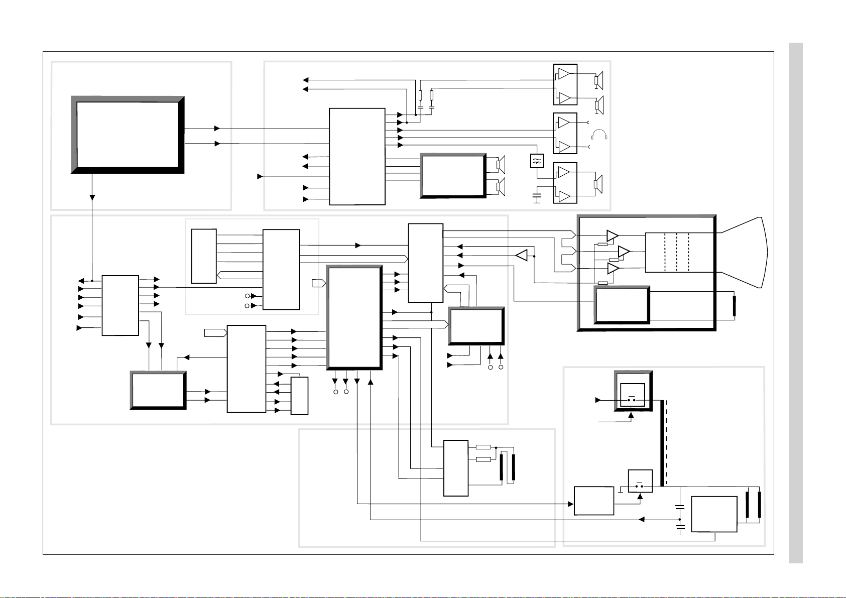
Block diagram, signal routes
15
20, 22, 24
19
10-12
13
fb
2-4
1
fb
bcl
BC
8
6
7
ICt1
ICr2
44-46
18-27
ICr1
47
BLAN
14
13
12
Y
ICd1
25
26
V
U
ICd3
4
2
3
1
RGB + fb
17
18
16
15
14
C
CVBS/Y
C
ICq1
OUT
OUT
13
3
11
IN
IN
CVBS/Y
5, 6
IN
8, 10
IN
2H
2V
14
sc
17
11
HA
VA
10
SSc
D1
D0
D2
D3
32
33
34
35
I/O2
I/O1
I/O3
I/O4
2
1
24
25
9
CVBS
3
2V
4
2H
A0-A9
RGB
ICs1
Mk1
DATA IN
DATA OUT
WS
L
R
CL
L, R
L, R
L, R
AM
SIF
R, L
R, L
L
R
3D/Pro Logic
module
AR7xx
4
6
1
7
ICa1
29
28
26
25
9
1
ICa2
2
6
33, 34
36, 37
46, 47
49, 50
52, 53
55
60
14
13
12
11
5
6
7
8
SOUND BLOCK
CRT module
HH7xx
ICh3
ICh2
ICh1
R
G
B
6
5
4
9
7
BC
SVM
module
VMxxx
PIP
module
PP7xx
RGB
RGB
IQTV2
&
DPLL
DB7xx
Flyback
EW
Ver
Ver
Hor
sc
11
14
12
16
Comb filter
module
CF7xx
V
Y
U
11
10
67
13
15
14
18-21
Scart 1
34
35
33
37
38
Camera
Scart 2
Scart 1
RF BLOCK
PIP
module
109
C
CVBS/Y
11 12
Scart 2
Scart 2
RGB
2H
2V
27 26
24
TELETEXT
VIDEO BLOCK
Adjustable
audio
Scart 1
Camera
Scart 3
VGA
Scart 2
Scart 1
17
Y
Tk3
SWxxx
U1
12V
22
17
20
19
18
12
11
1
9
2
Scart 1
26
Y
SVM coil
Diode
modulation
Dk7, Dk8
Tk4,ts1,ts2
5
Vertical
deflection
yoke
Horizontal
deflection
yoke
Line
driver
Tk1, Tk2
Vertical
deflection
and
E-W driver
Horizontal
deflection
5,9-12,14-18
MSP3410D
Audio
processor
TDA9143
Colour
decoder
TDA4780
RGB processor
SDA5275S
Megatext
514400
Text memory
TEA6417
Video switch
TDA8354
Vertical output
TDA2616
Audio power
amplifier
TL082
Headphone
amplifier
TV-Frontend
Tuner+IF
19
18
20
PIP
CVBS
1
Scart 3
IN
IN
23
1
Fsc
clock
VGA
VGA/RGB
5
6
4
ICa4
1
9
TDA2616
Active subwoofer
amplifier
ICa3
31
SUB
3
Page 6
4
Scart-
buffers
TXT
ICr1
RAM
ICr2
Delay
ICd3
Deco/Sync
ICd1
RGB-proc.
ICt1
ROM
ICf1
NVM
ICf2
µP
ICf3
Video Switch
ICq1
HP-Ampl.
ICa3
Service
conn. &
buffer
Sound
processor
ICa2
Frontend
PIF SIF
TV-
Tuner
ICo6
Rec
ICo3
Rec
5V-r
12V-r
To4
Pict
12V-p
SVM module
CRT-module
8V-p
FEATURE BOX
32
30
8V-p
Comb-Filter
3
4
PIP-module
Decoder
ICp3
µP, ICp6
&
A/D, ICp5
13
12V-p
7V-fb
8V-p
12V-p
7
28
5
5V-r
Amplifiers
Digital Sound
Processor
5V-r
12
1
28V
ICo4
12V-r
10V
5V-stb
Control module
IR-
receiver
8
10
6
12V-p
5V-stb
Loudspeaker
Amplifier
ICa1
PP7xx
Rq48
AR7xx
FC7xx
CF7xx
20
22
23
24
15
17
18
14
21
19
3
4
ICo2
3
2
11
5
ICo1
6
16
1
14
Ro8,
14
Do8
Co10
Do2
Do1
Do4
Do3
Ro4, 10
Ro15
Ro18, 19
21, 22
To1
Ro70
Co15
230V
50Hz
Ftc1
Fo1
Do12
Do11
Do9
Do13
U1
32
PWM
Line
sync.
Do17
Ro32
Fo3
Fo2
Do14
Do16
Ro42
Ro45
Ro50
Do20
8
2
5
!
!
Ro44, 46
ZDk1
7V
Mains non isolated
17V
7V-fb
Ro49
Ro48
!
Mo2
!
Mo3
!
Vert.deflection
& EW driver
ICs1
Mk1
Rk2
Dk1
8
10
11
12
1
7
Rk9
Dk2
Rk19
Dk3
6.3V RMS
30kV
500V
8 kV
Rk15
Rk45
200V
53V
Rk4
!
!
!
!
!
Tk3
Rk20
!
16V
SWxxx
Rk11, 12
13, 14
HH7xx
Line
driver
12V-p
12V-p
12V-p
!
7V
G2
Focus
Heater
5
4
3
6
12V-p
8V
Ra18
AUX
module
12V-p
TA700
And
ICf4
Reset
ICf5
Subwoofer
Amplifier
ICa4
I
2
C Switch
11
30V
2
30V
Rq54
Rq2
Tq5
8.5V
Rr18
Scart 3 module
TA710/711
4
10
Tuner
To15
To9
Cfc23
FC7xx
Control module
Start
ICfc1
ICfc2
2
1
47
14
Cfc24
Cfc26
Dfc11
Hfc2
3
Zdo1,To8
RGB
Switch
ICp7
I
2
C Switch
ttp5
IF
ICp1
Delay-line
ICp4
DB7xx
SR7xx
Cancellor
VMxxx
Defl. ctrl
IC17
Filters
5V
3V
IC1
DSP
IC4
IQTV
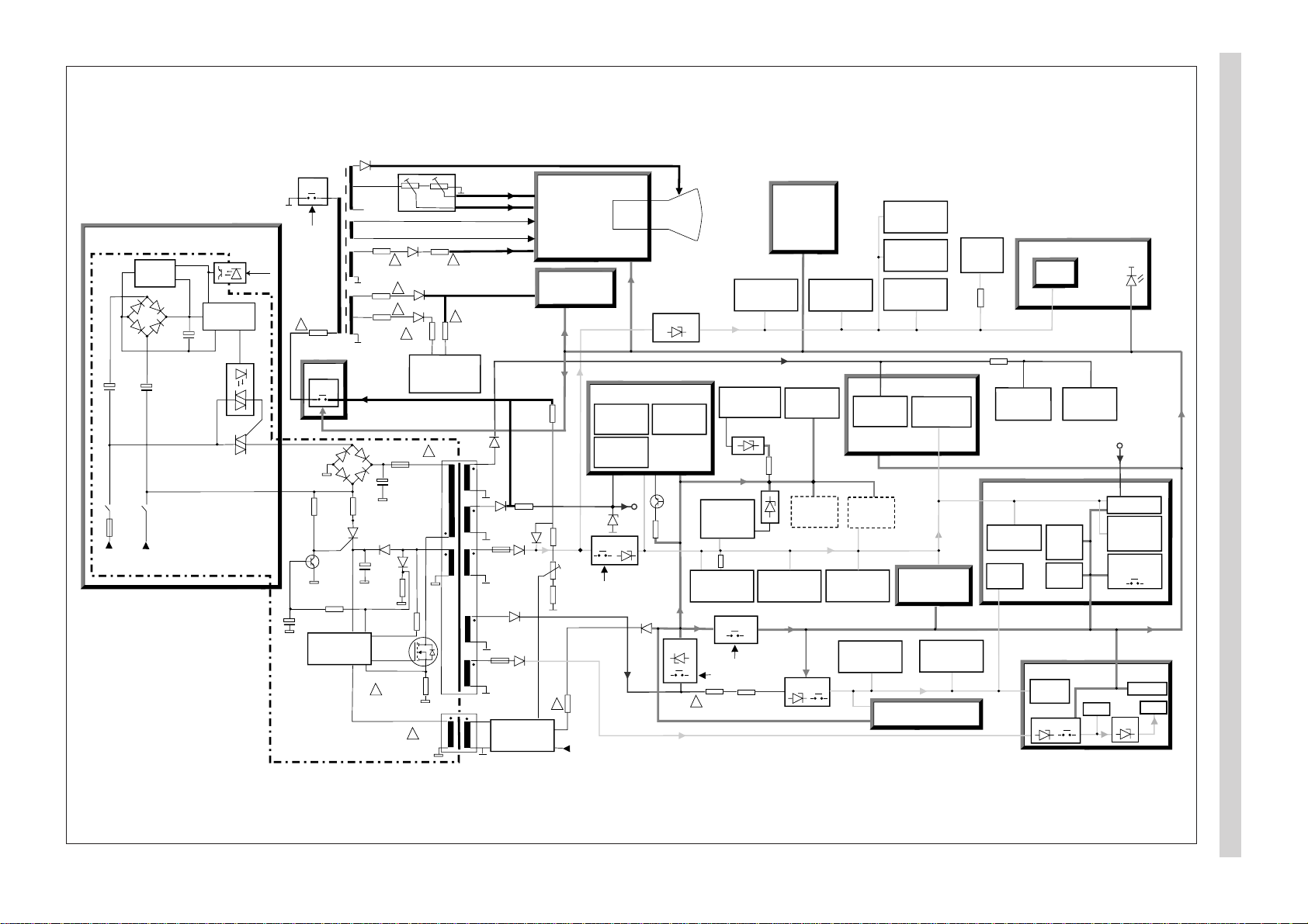
Block diagram, power supply
Page 7
µP
ICf3
PIP-MODULE
FEATURE BOX DB7xx
Comb-Filter
module
TV tuner
SDA
SCL
+5V
Local control
HP ind
Rec / IR
IR Receiver
TXT
ICr1
M3L
Status 2
Status 1
Status 3
Hold
Surround
processor
ICar2
Sound
processor
ICa2
Deflection
IC 17
IQTV µP
IC 18
Deco/Sync
ICd1
Subwoofer
mute
5
MSP Reset
Bypass /
Comb-ID
NTSC
RGB processor
ICt1
Video Switch
ICq1
NVM
ICf2
PIP µP
ICp6
Deco/Sync
ICp3
Video switch
PIP/ext. RGB
Service
connector
54
53
52
7
50
1
61 62
46
64
44, 45
4, 59, 60
AUDIO FEATURE BOX
17, 18
5, 6
8, 9
17, 18
5, 6 2, 4 27, 28
9, 10
49, 50, 51
51, 61
85
DPLL
IC 11
40, 41
9,10
24
40,41
3, 4
1, 2
3
PIP tuner
IF
ICp1
L-norm
15
16
37
38
VGA
1/2 FM
Bridges:
Mute
2
7
E3-control
(3-state)
&
APSi
test
Subwoofer
ident.
RGB
status
Line-out
status
6
3
FRONTEND
Multi: Strobe to write I/O-latch
Single: APSi control
IF ident.
resistor
APSi filter/Strobe
Strobe
APSi
(Single norm)
47
55
IF Ident.
15
16
23
13
2
1
5, 6
FSC /
SVHS
263
AV-link
PWM
Scart pin 10
16:9 ident.
51
12Vp
PA-mute
&
OR
28V
PA
PA
mute
mute
Subwoofer
Int-LS
15
4
I
2
C
I
2
C
DSP Reset
12V
4, 57, 8
10
A/D
Hor. shift
5
A/D
A/D
A/D
4, 5
8
8
ΤΑ700
8,9
Picture tilt
PWM
1
)
1
)
1) If no mux. and
picture tilt
mux.
ΤΑ710
Upict
Urec
U
49
48
Start
Rec-on
Pict-on
11 = Off
00 = TV
01 = Record
10 = Service
3
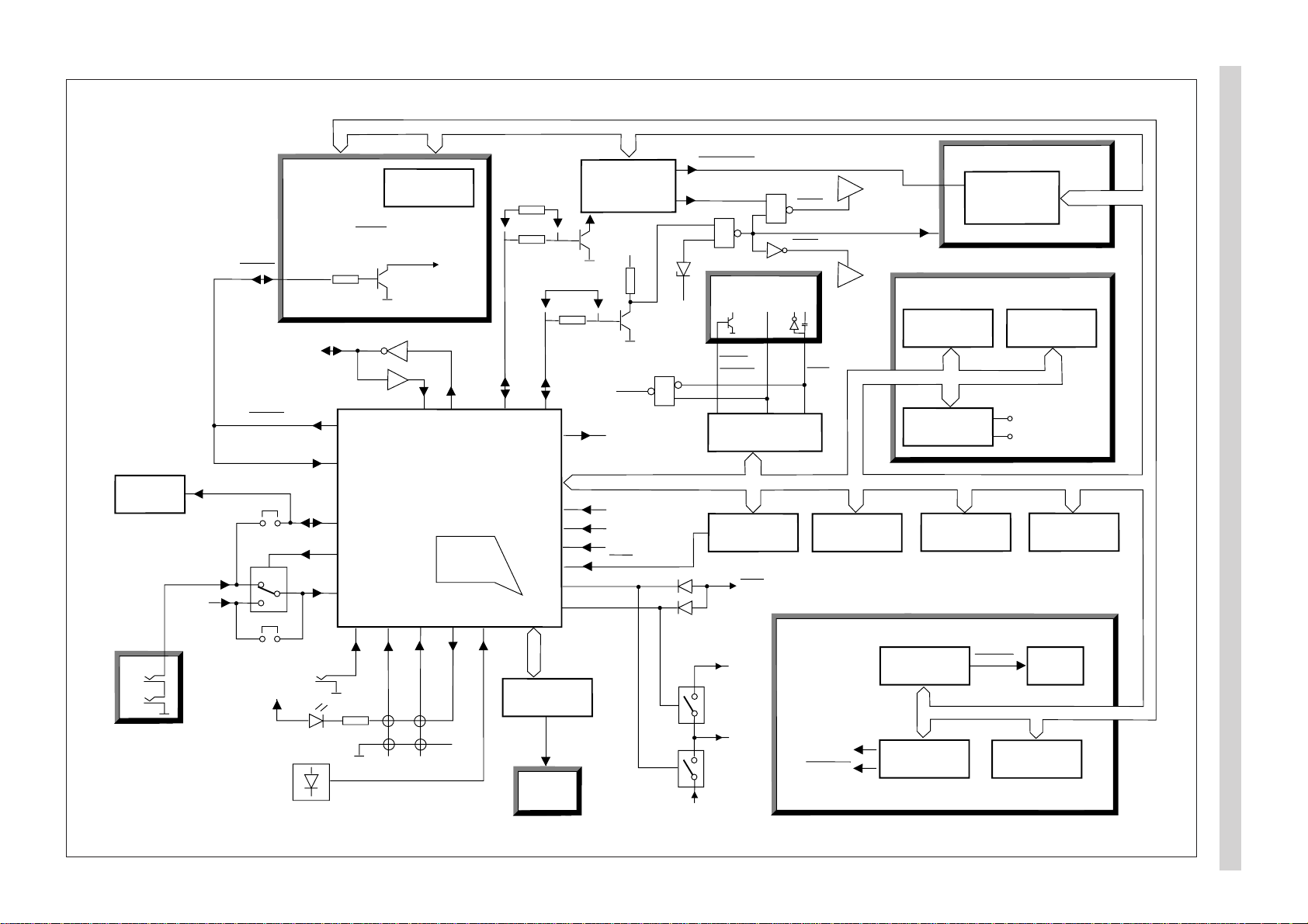
Block diagram, control signals
5
Page 8
6
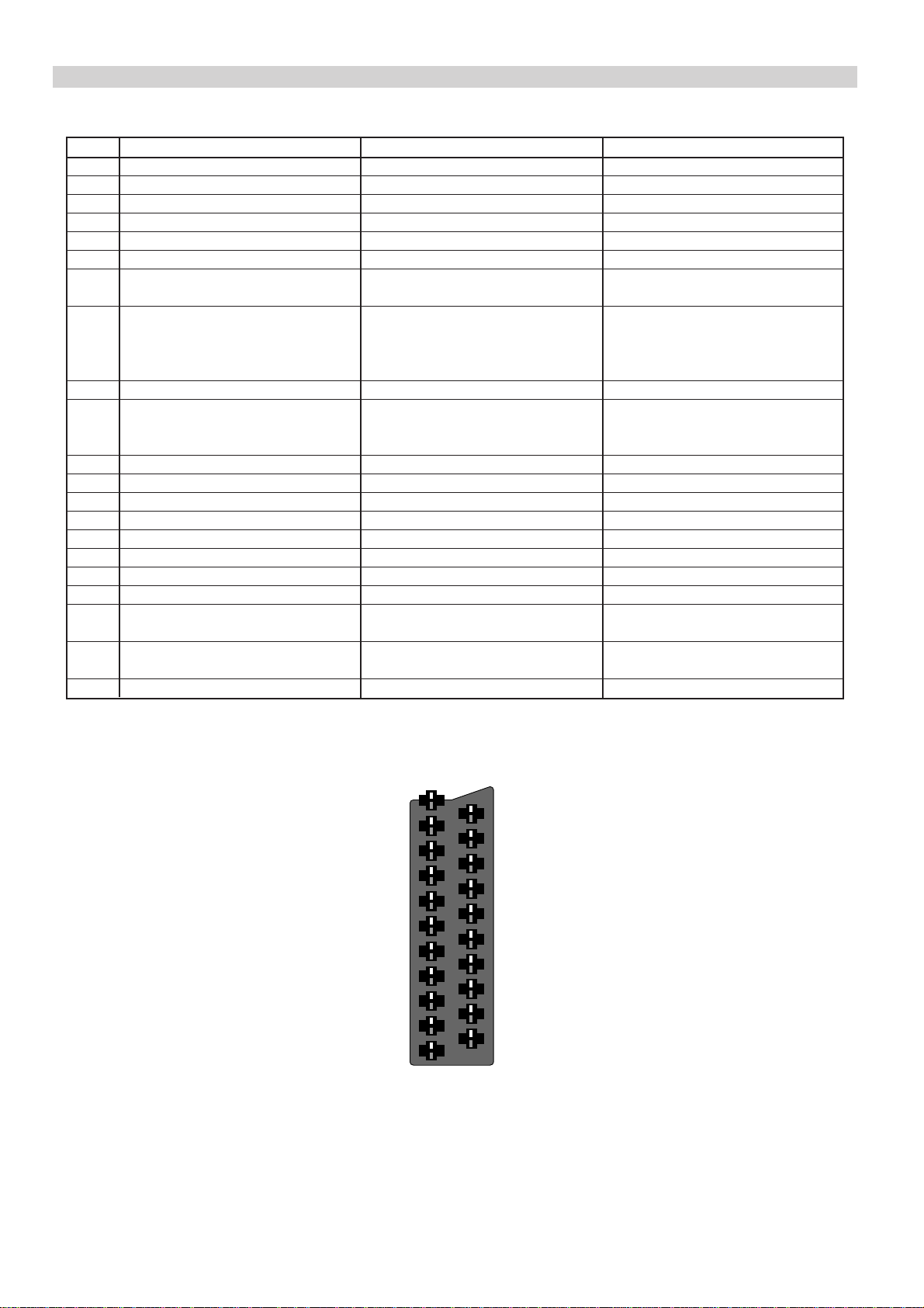
SCART connector
Pin SCART 1 SCART 2 SCART 3 (Not in all models)
1 Audio out R, 0.5V (RMS) Audio out R, 0.5V (RMS) Audio out R, 0.5V (RMS)
2 Audio in R, 0.5V (RMS) Audio in R, 0.5V (RMS) Audio in R, 0.5V (RMS)
3 Audio out L, 0.5V (RMS) Audio out L, 0.5V (RMS) Audio out L, 0.5V (RMS)
4 Ground, audio Ground, audio Ground, audio
5 Ground, blue Ground Ground, blue
6 Audio in L, 0.5V (RMS) Audio in L, 0.5V (RMS) Audio in L, 0.5V (RMS)
7 RGB input, blue S-video chrominance out RGB input, blue
(copy from front AV-connector)
8 Switching voltage Switching voltage Switching voltage
0 - 2V : no function 0 - 2V : no function 0 - 2V : no function
4.5 - 7V : 16/9 picture ratio 4.5 - 7V : 16/9 picture ratio 4.5 - 7V : 16/9 picture ratio
9.5 - 12V : normal picture ratio 9.5 - 12V : normal picture ratio 9.5 - 12V : normal picture ratio
9 Ground, green Ground Ground, green
10 - AV-link bidirectional control -
logical 0: max 0.6V
logical 1: min 3.7V
11 RGB input, green - RGB input, green
12 --13 Ground, red S-video ground (chrominance) Ground, red
14 Ground Ground Ground
15 RGB input, red S-video input (chrominance) RGB input, red
16 Switching voltage, RGB blanking - Switching voltage, RGB blanking
17 Ground, video Ground, video Ground, video
18 Ground Ground Ground
19 Video out, 1 Vpp/75 Ω Video out, 1 Vpp/75Ω Video out, 1 Vpp/75 Ω
S-video out (luminance)
20 Video in, 1 Vpp/75 Ω Video in, 1 Vpp/75 Ω Video in, 1 Vpp/75 Ω
RGB sync in S-video in (luminance) RGB sync in
21 Screen Screen Screen
21
19
17
15
13
11
20
18
16
14
12
9
7
5
3
1
10
8
6
4
2
Page 9
Operating instructions
7
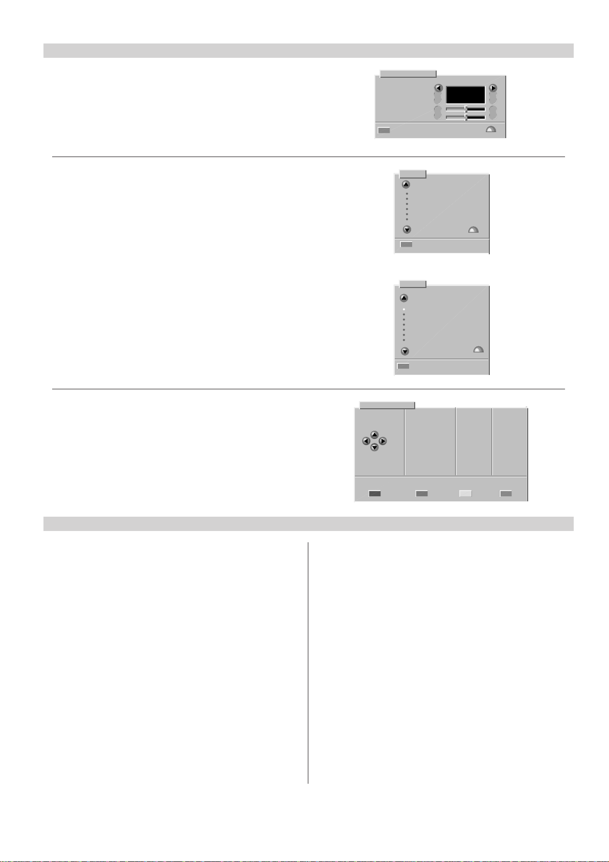
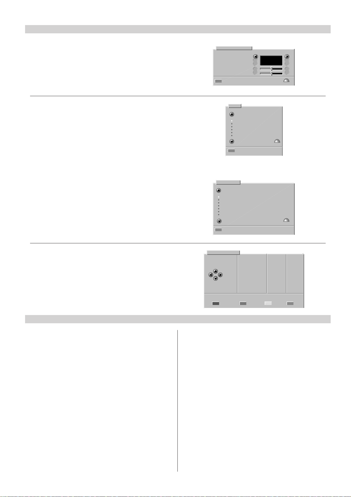
Changing the menu language
1. Press the yellow button to select the Vision menu.
2. Press the red button to select the Display set-up menu.
3. Change the menu language with cursor buttons.
4. Press the OK button to store the changes.
5. Press the TV button to exit.
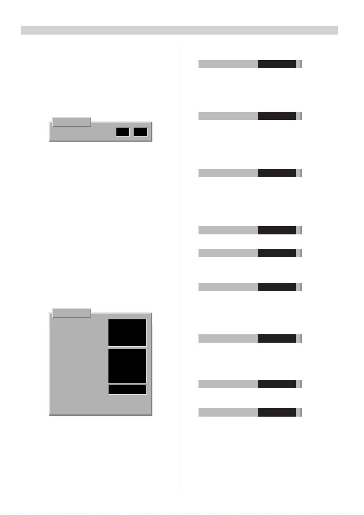
Manual tuning
1. Select the programme number you want to tune.
2. Press the MENU button.
3. Select “Tuning” and press the OK button.
4. Select “Manual tuning” and press the OK button.
5. Press the red button (Channel search).
6. Press the OK button to store.
7. Press the TV button to exit.
APSi (Automatic Programming System)
1. Press the MENU button.
2. Select “Tuning” and press the OK button.
3. Select “Automatic retuning” and press the OK button.
4. To retune the channels, press the red button.
5. Press the TV button to exit.
Display set-up
Program number
Volume bar
Menu language
Sharpness
Tint
Go back Store ª
Menu
Timers
Front panel lock
Locking
Tuning
Sort programs
Programme settings
Press ª
Go back
Tuning
Automatic retuning
Add new programs
Manual tuning
External units
Copy tuning to VCR
Copy tuning from VCR
Clear all programs
Press ª
Go back
HIDE
SHOW
ENGLISH
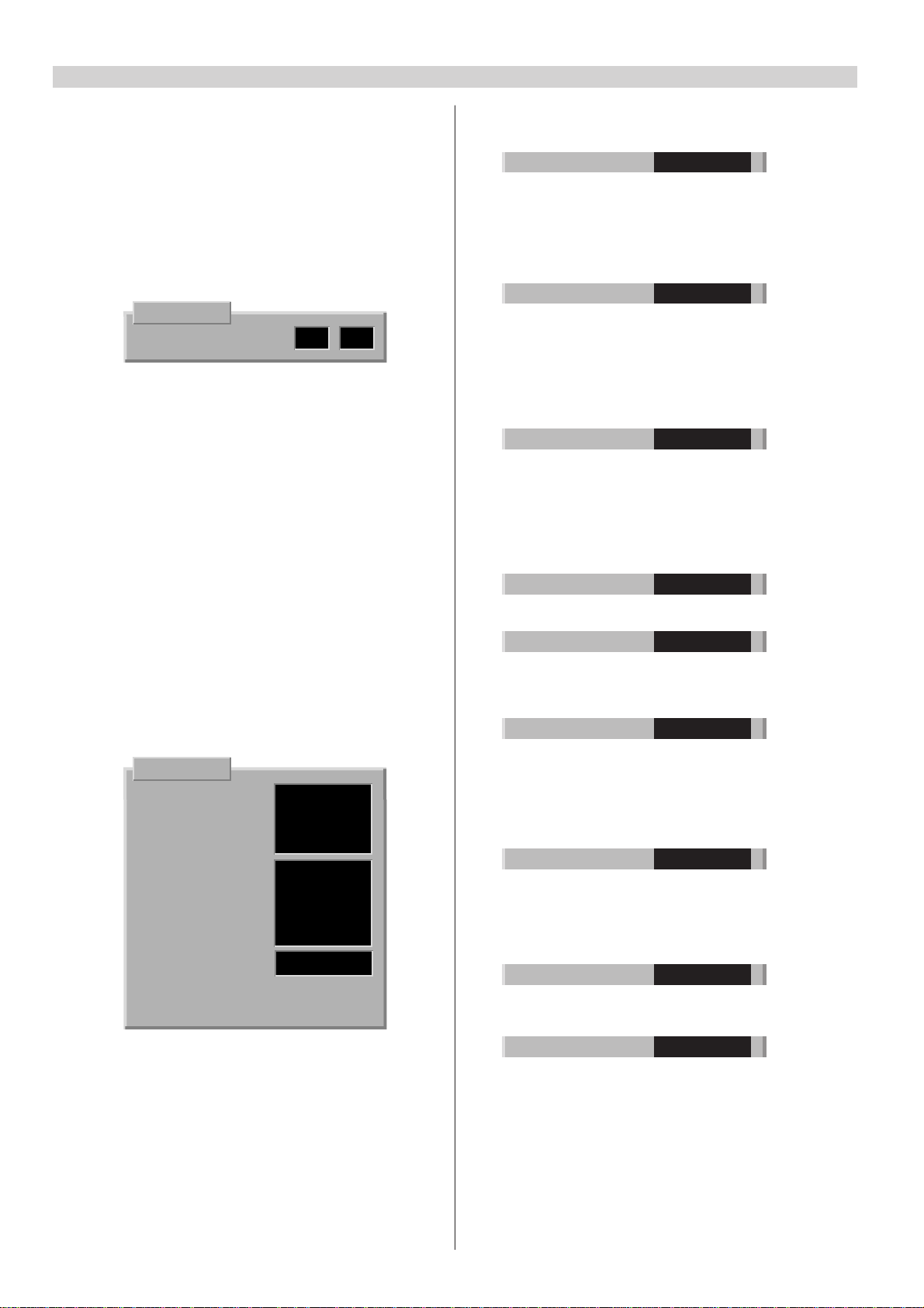
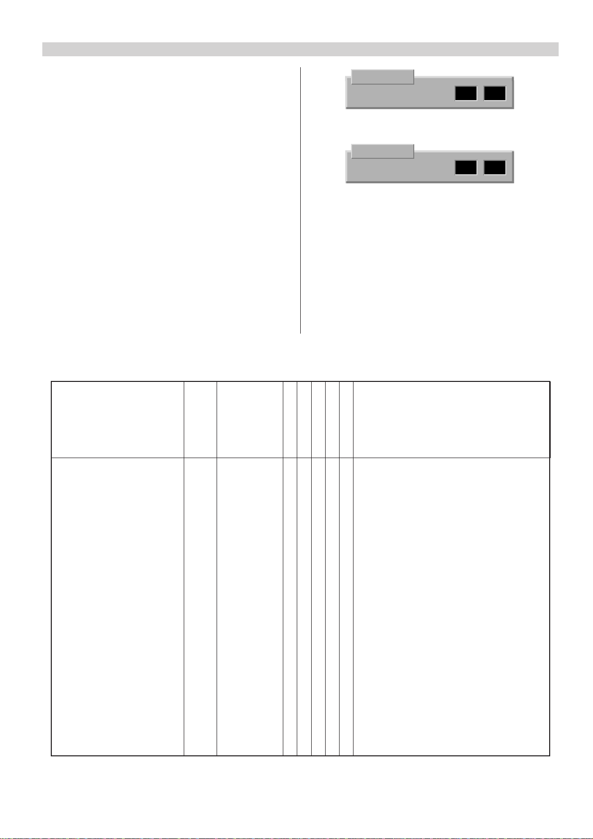
Selecting VGA input
1. Press the MENU button.
2. Select “Tuning” and press the OK button.
3. Select “External units” and press the OK button.
4. Select “VGA computer” and press the TV button.
(If “VGA computer” is not included in the list, select
“Add new unit” by pressing the red button.)
Initialization of NVRAM
Initialization of NVRAM (ICf2)
In case that the NVRAM is replaced, it must be initialized
and configured.
1. Switch the TV set to stand-by mode.
Press e- (volume minus) button on local control unit
and at the same time start entering password: MENU,
TV and i with the remote control. Release e- button
after the MENU button is pressed. The record led will
light up to indicate that service mode is enabled.
2. Press the RED-button to pre-configure the set. Green
led will flash once to indicate this.
3a. At the same time the controller will check NVRAM
and initialize it automatically if it was “empty”.
Initializing will take about 15 s. When it is completed,
the green led will light up. Continue to step 4.
3b.Automatic initialization did not happen if the green
led does not light up steadily. In some cases the led
might also light up immediately after configuration
without any initializing, depending on NVRAM
contents. In this case it might be enough to store the
new configuration by pressing “OK”. Continue to
step 4.
External units
A/V CAMERA
Select E2 VCR
unit VGA COMPUTER
choose from
alternatives
below
Add new Change unit Remove
unit settings unit Go back
3c. If automatic initialization did not happen, you can
start it manually by entering the key code: BLUE (wait
approx. 2 s.), 2, 5, 4 (wait approx. 2 s.) and OK.
Initializing will take about 15 s.
4. Switch off the receiver by pressing the mains switch.
5. Start the receiver in TV mode by pressing the mains
switch. Tune in one or more tv channels.
6. Switch off the receiver with remote control.
7. Enter service mode and make the service adjustments
(see section "SERVICE ADJUSTMENTS VIA I2C BUS").
8. Switch off the receiver by pressing the mains switch.
Page 10
8
Service adjustments
Service␣ mode␣ selection
1. Switch the TV set to stand-by mode.
2. Press e- (volume minus) button on local control unit
and at the same time start entering password: MENU,
TV and i with remote control. Release e- button after
the MENU button is pressed. The record led will light
up to indicate that service mode is enabled.
3. Switch on the receiver by pressing the TV button twice
and select service mode by pressing the i button.
SERVICE
00 V-AMPL. 38 36
In service mode an adjustment menu is shown on the
screen.The adjustment number and name, initializing
(left) and adjustment (right) values are shown in the
menu.
4. Exit service mode by switching off the receiver with
the mains switch.
Configuration and fault diagnosis
The set must be configured after adding or removing
some options. By pressing the RED button in service
mode, the processor checks the configuration of the TV
set and shows the settings on the screen. The
configuration can be stored by pressing the OK button.
This feature can also be used in fault diagnosis. If an
option bit is not ’1’ when it should be, the IC (or feature)
is either not present or faulty.
Changing the option bytes
1. Select the configuration mode by pressing the RED
button in service mode.
SERVICE
IIC DEV 1 11111001
IIC DEV 2 00000110
IIC DEV 3 00010100
IIC DEV 4 00000001
IF OPT 00000001
TXT OPT 00000001
SYS OPT 1 00111111
SYS OPT 2 00000000
DSP OPT 00000000
UIF FLAGS 00110010
SW VER. MCABxx.x
NVM VER. MCA1-xx
SW VER. = µP software version.
NVM VER. = NVM software version.
2. Select IIC Device byte 1 - 4, Option byte 1 - 5 or uif
flags byte with cursor button (up-/downwards).
Selected byte is shown highlighted.
3. Set the bits with number buttons (0 ... 7).
4. Store the settings by pressing the OK button.
5. Return to normal service mode by pressing the RED
button.
Option byte description
Bit Description ‘1’ ‘0’
76543210
IIC DEV 1 11111001
0 TV tuner Yes No
1 IF Output, HEF4094 Yes No
3 Decoder synch. processor, TDA9143 Yes No
4 Deflection controller, TDA9151 Yes No
5 RGB processor, TDA4780 Yes No
6 IQTV processor Yes No
7 DPLL Yes No
IIC DEV 2 00000110
0 VGA Yes No
1 Main video switch, TDA6417 Yes No
2 Audio processor, MSP3410 Yes No
3 16:9 picture tube Yes No
4 Comb filter Yes No
5 PIP processor, SDA9188 + TDA9141 Yes No
6 PIP tuner Yes No
7 SCART 3 installed Yes No
IIC DEV 3 00010100
0 Virtual sound (3D Sound) Yes No
1 Dolby processor Yes No
2 SDA30C264 processor Yes No
3 Subwoofer Yes No
4 Megatext, SDA5273/75 Yes No
5 External text memory Yes No
6 Level 2.5 Megatext Yes No
7 One field memory (DB711 Module) Yes No
IIC DEV 4 00000001
0 Nicam enabled Yes No
1 Control lead (Xata) to AR7xx module Yes No
IF OPT 00000001
0 B/G system Yes No
1 I system Yes No
2 D/K system Yes No
3 L/L’ system Yes No
TXT OPT 00000001
0 Top enabled Yes No
1 Flof enabled Yes No
2 P26 disabled Yes No
3 Text sync mode Yes No
4 Automatic text subpage rolling Yes No
5 EPG (nexTView) enabled Yes No
6 EPG record enabled Yes No
SYS OPT 1 00111111
0 E0 (A/V connector) installed Yes No
1 E0 S-video Yes No
2 RGB enabled only in E1 Yes No
3 ACI enabled Yes No
4 Micro power supply installed Yes No
5 Carrier mute enabled Yes No
SYS OPT 2 00000000
0 Picture Tilt enabled Yes No
1 Autostart (Hotel TV) Yes No
7 Hotel TV functions enabled (manual) Yes No
UIF FLAGS 00110010
0-2 Logo bit
000 = no logo, go direct to APSi
001 = no logo, go to language menu
010 = Akai logo
011 = Nokia logo
100 = Finlux logo
101 = Salora logo
110 = Luxor logo
3 TV set not used before Yes No
4 Volume bar enabled Yes No
5 On screen programme number enabled Yes No
6 Front panel lock Yes No
7 Off timer active Yes No
Page 11

Service adjustments via I2C-bus
9
Remote␣ control␣ buttons␣ in␣ service␣ mode
When the receiver is in service mode you can select the
normal TV mode by pressing the TV button and return to
the service mode by pressing the i button.
Number and cursor buttons are used for service
adjustment. The OK button stores the settings.
Adjustment for different picture format
Make all adjustments with PAL signal unless otherwise
mentioned. First make all adjustments with normal 4:3
picture format. Then make the necessary adjustments
with other picture formats/signals. The required
adjustments are shown in the table below.
Note! Check the configuration of the TV set before
making the adjustments and make only the necessary
adjustments.
Making the service adjustment
1. Give a two numbered code which determines the
adjustment (e.g. 06 = width, see the following tables)
with the number buttons. You can also select the
adjustment with cursor buttons (up-/downwards).
Picture geometry adjustments
SERVICE
06 WIDTH 49 33
2. Adjust with cursor buttons (left/right).
SERVICE
06 WIDTH 49 36
3. Store the new value by pressing the OK button.
Note!
• To avoid incomplete adjustments store each
adjustment in the memory immediately after
adjusting.
• If the adjustment has to be made separately for
different picture format/signal, select the normal user
mode by pressing the TV button and select the desired
picture format/signal. Return to service mode by
pressing the i button.
classic (4:3)
wide movie
VGA 60 Hz
VGA 70 Hz
Adjustment Code OSD name Note!
Vertical amplitude 00 V-AMPL. X X X
Vertical off-centre shift 01 V-SHIFT X X
Vertical start scan 02 V-START X X X
Vertical S-correction 03 S-CORR. X X X
Vertical slope (coarse) 04 SLOPE-H X X X Adjust also with NTSC signal.
Vertical slope (fine) 05 SLOPE-L X Adjust also with NTSC signal.
Width 06 WIDTH X X X
Horizontal shift deflection 07 H-SHIFT X Not in all sets.
Horizontal phase video 08 PHASE X X X X
Parabola 09 PARABOLA X X X
Corner 10 CORNER X X X
Trapezium 11 TRAPEZIUM X X
EHT compensation 12 EHT X X Set brightness and contrast to 90% and
RGB
compensate the change in picture size.
VGA 60 Hz = Windows mode
VGA 70 Hz = DOS mode
Page 12
10
Other adjustments
Adjustment Code OSD name
Red reference 18 R REF.
Green reference 19 G REF.
Blue reference 20 B REF.
Red gain 15 R GAIN
Green gain 16 G GAIN
Blue gain 17 B GAIN
Peak white limit 21 PWL
Luma delay 14 LUMA DELAY
Service adjustments
O Power supply block
Supply voltage and protection circuit
1. Set brightness and contrast to normal level. Connect a
universal voltmeter to the cathode of Do11.
2. Adjust the U1 voltage with Ro45. The voltage depends
on the picture tube type, refer to the section “Variable
components”.
Note!
This procedure is necessary e.g. when the picture tube, CRTmodule etc. has been replaced.
Apply a test picture and adjust the R, G and B references.
Then adjust the R, G and B gains.
Normally no need to adjust.
Separate adjustment for Video, PAL BG, PAL DK/I and Secam L.
K Horizontal deflection block
Horizontal linearity
Adjust with Lk2.
Focusing
Set brightness and contrast to normal level. Use
crosshatch pattern and adjust the picture for optimum
resolution.
3. Check the over-current protection after making any
service operations in the primary circuit of the power
supply. Activate the service mode and then switch the
set to stand-by mode. Short circuit the cathode of
Do13 to the ground and keep the short circuit
connected. When the over-current protection works
correctly, the power supply will try to start 2-3 times
before it stops permanently. Remove the short circuit
and switch on the receiver by pressing the mains
button.
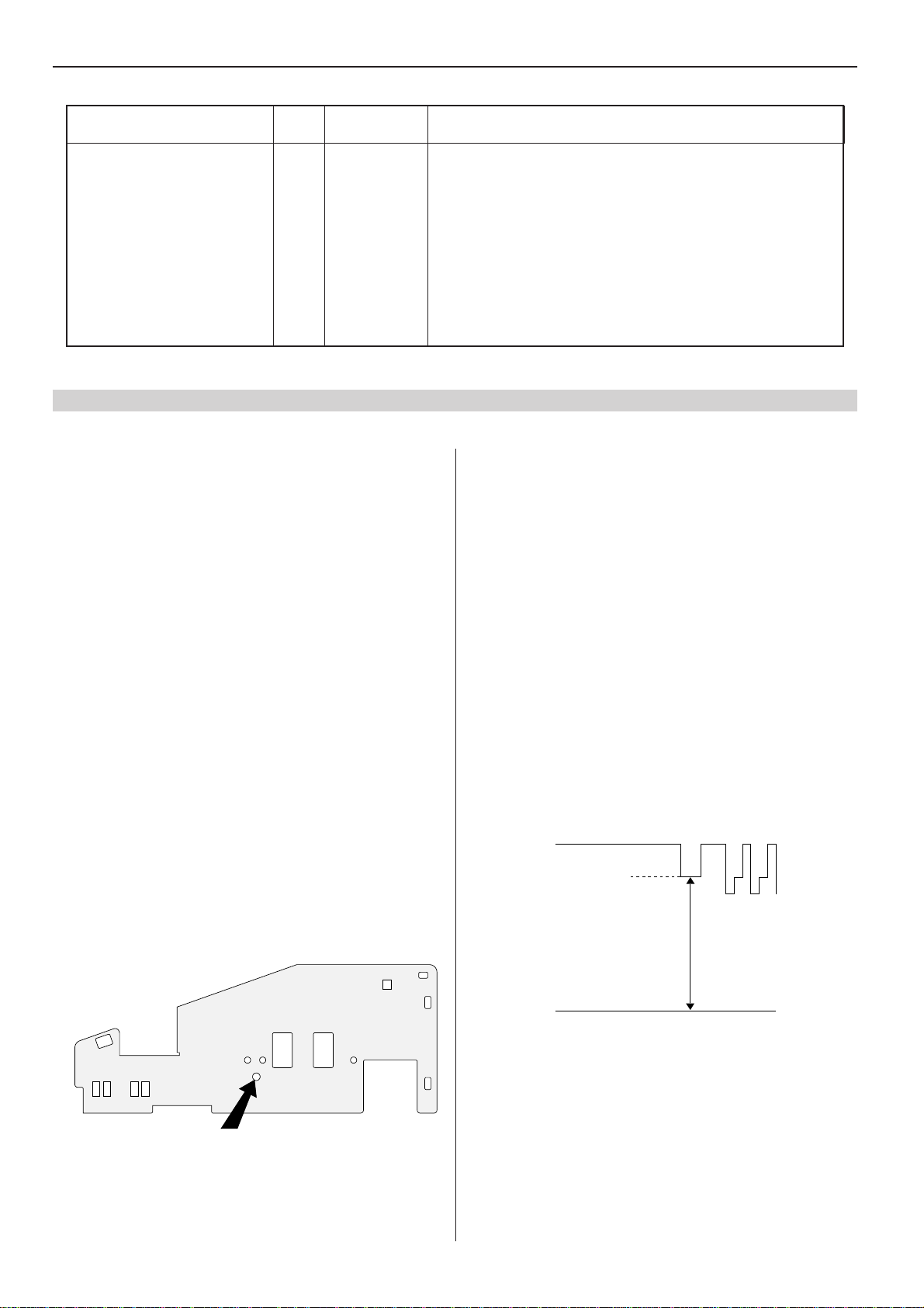
SR Tuner/IF module (Frontend)
Tuner AGC
The tuner AGC is adjusted with a potentiometer through
a hole in the heat sink (see picture below).
Apply a 1 mV (60 dBµV) test signal and adjust the picture
just without noise.
81403760
(Screen grid voltage) Ug2 voltage
1. Set brightness and colour saturation to normal level
and contrast to minimum.
2. At the end of the vertical blanking, there is a black
current measurement pulse (clamp pulse) at pin 9 of
ICh1, ICh2 and ICh3. Use an oscilloscope and find the
output stage with the highest cut-off (i.e. the highest
voltage during the black current measurement pulse).
3. Adjust the voltage of the clamp pulse to +140 V with
Ug2 (see figure).
clamp pulse
140 V
0 V
Note! Adjust the voltage with a clamp pulse.
AGC
Page 13
Bedienungsanleitung
11
Ändern der Menüsprache
1. Drücken Sie die gelbe Taste zur Wahl des Bildmenüs.
2. Drücken Sie die rote Taste zur Wahl des AnzeigeOptionen-Menüs.
3. Ändern Sie die Menü Sprache mit den Cursortasten.
4. Drücken Sie zum Speichern der Änderungen die OKTaste.
5. Drücken Sie zum Verlassen des Menüs die TV-Taste.
Manuelle Abstimmung
1. Wählen Sie die Programmnummer, die Sie abstimmen
möchten.
2. Drücken Sie die MENU-Taste.
3. Wählen Sie “Abstimmung” und drücken Sie die OK-Taste.
4. Wählen Sie “Senderabstimmung” und drücken Sie die
OK-Taste.
5. Drücken Sie die rote Taste (Kanal-Suchlauf).
6. Drücken Sie zum Speichern die OK-Taste.
7. Drücken Sie zum Verlassen des Menüs die TV-Taste.
APSi (Automatisches Programmiersystem)
1. Drücken Sie die MENU-Taste.
2. Wählen Sie “Abstimmung” und drücken Sie die OK-Taste.
3. Wählen Sie “Neuprogrammierung” und drücken Sie die
OK-Taste.
4. Drücken Sie zur Neuabstimmung der Kanäle die rote
Taste.
5. Drücken Sie zum Verlassen des Menüs die TV-Taste.
Anzeige-Optionen
Programm-Nr.
Lautstärke Balken
Menü Sprache
Bildschärfe
Farbton
Zurück Speichern ª
Menü
Timer
Tasten verriegelt
Verriegeln
Abstimmung
Sortieren
Programmeinstellungen
Drücken Sie ª
Zurück
Abstimmung
Neuprogrammierung
Neue TV-Programme suchen
Senderabstimmung
Externe Geräte
Kopiere Abstimminformation zum VCR
Kopiere Abstimminformation vom VCR
Alle Programme löschen
Drücken Sie ª
Zurück
UNSICHTB.
SICHTBAR
DEUTSCH
Wahl des VGA-Eingangs
1. Drücken Sie die MENU-Taste.
2. Wählen Sie “Abstimmung” und drücken Sie die OK-Taste.
3. Wählen Sie “Externe Geräte” und drücken Sie die OKTaste.
4. Wählen Sie “VGA Computer” und drücken Sie die OKTaste. (Falls “VGA Computer” nicht in der Liste
enthalten ist, wählen Sie “Neues Gerät hinzufügen”
durch Drücken der roten Taste.)
Initialisierung des NVRAM
Initialisierung des NVRAM (ICf2)
Im Falle eines Austausches des NVRAM muß dieser
initialisiert und konfiguriert werden.
1. Schalten Sie das Fernsehgerät in die
Betriebsbereitschaft.
Drücken Sie die e-Taste (Lautstärke-Minus) an der
Bedieneinheit, während Sie gleichzeitig die Eingabe des
Paßwortes mit der Fernbedienung starten: MENU, TV
und i. Lassen Sie die e-Taste los, nachdem die MENUTaste gedrückt wurde. Die Aufnahme-LED leuchtet auf
und zeigt an, daß der Servicemodus aktiviert ist.
2. Drücken Sie zur Vorkonfiguration des Fernsehgerätes
die rote Taste. Die grüne LED leuchtet zur Kontrolle
einmal auf.
3a. Zur gleichen Zeit überprüft der Controller den NVRAM
und initialisiert ihn automatisch, wenn er “leer” war.
Die Initialisierung dauert ungefähr 15 Sekunden. Wenn
sie durchgeführt worden ist, leuchtet die grüne LED auf.
Fahren Sie mit Schritt 4 fort.
3b. Die automatische Initialisierung wurde nicht
durchgeführt, wenn die grüne LED nicht dauernd
aufleuchtet. In manchen Fällen kann die LED direkt nach
Externe Geräte
A/V CAMERA
Wählen Sie das E2 VCR
externe VGA COMPUTER
Geräte aus
Wählen Sie von
untenstehenden
Alternativen
aus
Neues Gerät Einstellung Gerät
hinzufügen verändern entfernen Zurück
der Konfiguration ohne jede Initialisierung aufleuchten,
abhängig vom Inhalt des NVRAM. In diesem Fall ist es
ausreichend, die neue Konfiguration durch Drücken der
OK-Taste zu speichern. Fahren Sie mit Schritt 4 fort.
3c. Ist die automatische Initialisierung nicht durchgeführt
worden, kann diese manuell durch Eingabe des
Schlüsselcodes gestartet werden: BLAUE (ca. 2
Sekunden warten), 2, 5, 4 (ca. 2 Sekunden warten), und
OK. Die Initialisierung dauert ungefähr 15 Sekunden
4. Schalten Sie das Fernsehgerät durch Drücken des
Netzschalters aus.
5. Schalten Sie das Fernsehgerät durch Drücken des
Netzschalters in den Fernsehbetrieb. Stellen Sie einen
oder mehrere Kanäle ein.
6. Schalten Sie das Fernsehgerät mit der Fernbedienung
aus.
7. Gehen Sie in den Servicemodus und nehmen Sie die
Service-Einstellungen vor (siehe Abschnitt “SERVICEEINSTELLUNGEN ÜBER DEN I2C-BUS”).
8. Schalten Sie das Fernsehgerät mit dem Netzschalter
aus.
Page 14
12
Service-Einstellungen
Wahl des Servicemodus
1. Schalten Sie das Fernsehgerät in die Betriebsbereitschaft.
2. Drücken Sie die e-Taste (Lautstärke-Minus) an der
Bedieneinheit, während Sie gleichzeitig die Eingabe des
Paßwortes mit der Fernbedienung starten: MENU, TV
und i. Lassen Sie die e-Taste los, nachdem die MENUTaste gedrückt wurde. Die Aufnahme-LED leuchtet auf
und zeigt an, daß der Servicemodus aktiviert ist.
3. Schalten Sie das Fernsehgerät durch zweimaliges
Drücken der TV-Taste ein und wählen Sie den
Servicemodus durch Drücken der i-Taste.
SERVICE
00 V-AMPL. 38 36
Im Servicemodus wird ein Einstellmenü auf dem
Bildschirm gezeigt. Die Einstellungszahl und der Name,
die Initialisierung (links) und die Einstellwerte (rechts)
werden in diesem Menü gezeigt.
4. Verlassen Sie den Servicemodus durch Ausschalten
des Fernsehgerätes mit dem Netzschalter.
Konfiguration und Fehlerdiagnose
Nach Hinzufügen oder Entfernen von Optionen muß das
Fernsehgerät konfiguriert werden. Durch Drücken der
roten Taste im Servicemodus überprüft der Prozessor die
Konfiguration des Fernsehgerätes und zeigt die
Einstellungen auf dem Bildschirm an. Die Konfiguration
kann durch Drücken der OK-Taste gespeichert werden.
Dieses Feature kann auch bei der Fehlerdiagnose benutzt
werden. Wenn ein Option-Bit nicht ‘1’ ist - was dieses
aber sein sollte - ist der IC (oder das Feature) entweder
nicht vorhanden oder defekt.
Änderung der Options-Bytes
1. Wählen Sie den Konfigurationsmodus durch Drücken
der roten Taste im Servicemodus.
SERVICE
IIC DEV 1 11111001
IIC DEV 2 00000110
IIC DEV 3 00010100
IIC DEV 4 00000001
IF OPT 00000001
TXT OPT 00000001
SYS OPT 1 00111111
SYS OPT 2 00000000
DSP OPT 00000000
UIF FLAGS 00110010
SW VER. MCABxx.x
NVM VER. MCA1-xx
SW VER. = µP Softwareversion.
NVM VER. = NVM Softwareversion.
2. Wählen Sie das IIC-Gerätebyte 1 -4, das Prüfbyte 1 - 5
oder das uif-Kennzeichenbyte mit den Cursortasten
(auf-/abwärts). Das gewählte Byte wird hervorgehoben
dargestellt.
3. Stellen Sie die Bits mit den Zifferntasten (0 ... 7) ein.
4. Speichern Sie die Einstellungen durch Drücken der
OK-Taste.
5. Kehren Sie durch Drücken der roten Taste zum
normalen Servicemodus zurück.
Beschreibungen der Options-Bytes
Bit Beschreibung ´1´ ´0´
76543210
IIC DEV 1 11111001
0 TV-Tuner Ja Nein
1 IF-Ausgang, HEF4094 Ja Nein
3 Synchronprozessor Decoder, TDA9143 Ja Nein
4 Ablenkungssteuerung, TDA9151 Ja Nein
5 RGB-Prozessor, TDA4780 Ja Nein
6 IQTV-Processor Ja Nein
7 DPLL Ja Nein
IIC DEV 2 00000110
0 VGA Option installiert Ja Nein
1 Hauptvideoschalter, TDA6417 Ja Nein
2 Tonprozessor, MSP3410 Ja Nein
3 16:9 Bildröhre Ja Nein
4 Kammfilter installiert Ja Nein
5 PIP-Prozessor, SDA9188 + TDA9141 Ja Nein
6 PIP-Tuner Ja Nein
7 SCART 3 installiert Ja Nein
IIC DEV 3 00010100
0 Virtueller 3D Ton Ja Nein
1 Dolby-Prozessor Ja Nein
2 SDA30C264-Prozessor Ja Nein
3 Subwoofer installiert Ja Nein
4 Megatext, SDA5273/75 Ja Nein
5 VT mit externen RAM Ja Nein
6 Level 2.5 Megatext Ja Nein
7 Einfeld-Speicher (DB711 Modul) Ja Nein
IIC DEV 4 00000001
0 Nicam aktiviert Ja Nein
1 Steuerleitung (Xata) an AR7xx-Modul Ja Nein
IF OPT 00000001
0 B/G-System Ja Nein
1 I-System Ja Nein
2 D/K-System Ja Nein
3 L/L’-System Ja Nein
TXT OPT 00000001
0 Toptext aktiviert Ja Nein
1 Floftext aktiviert Ja Nein
2 TXT packet P26 nicht aktiviert Ja Nein
3 Text-Synchronmodus Ja Nein
4
Autom. Weiterblättern von Textunterseiten
5 EPG (nexTView) aktiviert Ja Nein
6 EPG-Aufnahme aktiviert Ja Nein
Ja Nein
SYS OPT 1 00111111
0 E0 (A/V-Anschluß) installiert Ja Nein
1 E0 S-Video Ja Nein
2 RGB nur möglich bei E1 Ja Nein
3 ACI aktiviert Ja Nein
4 Micro Power Netzteil installiert Ja Nein
5 Tonträger Steuerschaltung Ja Nein
SYS OPT 2 00000000
0 Bilddrehung aktiviert Ja Nein
1 Autostart (Hotel TV) Ja Nein
7 Hotel TV-Funktionen aktiviert (manuell) Ja Nein
UIF FLAGS 00110010
0-2 Logo-Bit
000 = Kein Logo, direkt in das APSi gehen
001 = Kein Logo, in das Sprachmenü gehen
010 = Akai-Logo
011 = Nokia-Logo
100 = Finlux-Logo
101 = Salora-Logo
110 = Luxor-Logo
3 Fernsehgerät zuvor noch nicht benutzt Ja Nein
4 Lautstärkebalken aktiviert Ja Nein
5 Einblendung Programmnummer aktiviert Ja Nein
6 Verriegelung der Tasten am Gerät Ja Nein
7 Off-Timer aktiv Ja Nein
Page 15
Service-Einstellungen über I2C-bus
13
Tasten der Fernbedienung im Servicemodus
Wenn sich das Fernsehgerät im Servicemodus befindet,
können Sie den normalen Fernsehmodus durch Drücken der
TV-Taste wählen. Sie können durch Drücken der i-Taste zum
Servicemodus zurückkehren. Ziffern- und Cursortasten
werden zur Service-Einstellung benötigt. Die OK-Taste
speichert die Einstellungen.
Einstellungen für ein anderes Bildformat
Wenn nicht anders vermerkt, nehmen Sie alle Einstellungen
mit dem PAL-Signal vor. Führen Sie zuerst alle Einstellungen
mit dem normalen 4:3 Bildformat durch. Führen Sie dann die
notwendigen Einstellungen mit anderen Bildformaten bzw.
Signalen durch. Die erforderlichen Einstellungen werden in
der unten befindlichen Tabelle gezeigt.
Hinweis! Überprüfen Sie die Konfiguration des
Fernsehgerätes, bevor Sie die Einstellungen vornehmen;
nehmen Sie nur die nötigen Einstellungen vor.
Service-Einstellung vornehmen
1. Geben Sie mit den Zifferntasten den zweistelligen Code
ein, der die Einstellung bestimmt (z.B. 06 = Bildbreite,
siehe folgende Tabellen). Sie können die Einstellung auch
mit den Cursortasten wählen (auf-/abwärts).
SERVICE
06 WIDTH 49 33
2. Nehmen Sie die Einstellung mit den Cursortasten
(links/rechts) vor.
SERVICE
06 WIDTH 49 36
3. Speichern Sie den neuen Wert durch Drücken der OKTaste.
Hinweis!
•
Um unvollständige Einstellungen zu vermeiden,
speichern Sie jede Einstellung direkt nach dem
Einstellen ab.
•
Falls die Einstellung getrennt für verschiedene
Bildformate bzw. Signale durchgeführt werden muß,
gehen Sie durch Drücken der TV-Taste in den
normalen Betriebsmodus und wählen Sie das
gewünschte Bildformat bzw. Signal. Gehen Sie durch
Drücken der i-Taste in den Servicemodus zurück.
Einstellungen der Bildgeometrie
OSD
Einstellung Code Bezeichn. Hinweis!
Vertikale Amplitude 00 V-AMPL. X X X
Vertikale Lage 01 V-SHIFT X X
Vertikale Start-Zeile 02 V-START X X X
Vertikale S-Korrektur 03 S-CORR. X X X
Vertikale Steilheit (grob) 04 SLOPE-H X X X Auch mit dem NTSC-Signal einstellen.
Vertikale Steilheit (fein) 05 SLOPE-L X Auch mit dem NTSC-Signal einstellen.
Bildbreite 06 WIDTH X X X
Horizontale Lage der Ablenkung
Horizontale Lage Video 08 PHASE X X X X
07 H-SHIFT X Nicht in allen Geräten.
Classic
Movie (weit)
VGA 60 Hz
VGA 70 Hz
RGB
OW-Kissen 09 PARABOLA X X X
OW-Ecken Korrektur 10 CORNER X X X
OW-Trapez 11 TRAPEZIUM X X
EHT-Kompensation 12 EHT X X Stellen Sie Helligkeit und Kontrast auf 90%
ein und kompensieren Sie die Änderung
der Bildgröße.
VGA 60 Hz = Windows-Modus
VGA 70 Hz = DOS-Modus
Page 16

14
Weitere Einstellungen
OSD
Einstellungen Code Bezeichn.
Hinweis!
Rot-Referenz 18 R REF.
Grün-Referenz 19 G REF.
Blau-Referenz 20 B REF.
Rotverstärkung 15 R GAIN
Grünverstärkung 16 G GAIN
Blauverstärkung 17 B GAIN
Oberer Grenzwert weiß 21 PWL
Y-Verzögerungsleitung 14 LUMA DELAY
Service-Einstellungen
O Netzteil
Versorgungsspannung und Schutzschaltung
1. Stellen Sie Helligkeit und Kontrast auf den normalen
Wert ein. Schließen Sie ein Universalvoltmeter an die
Kathode von Do11 an.
2. Stellen Sie die Spannung U1 mit Ro45 ein. Die
Spannung hängt vom Bildröhrentyp ab, siehe auch
Abschnitt “Röhrenabhängige Bauteile”.
3. Prüfen Sie den Überstromschutz nach Durchführung
von Servicearbeiten im primären Schaltkreis der
Stromversorgung. Aktivieren Sie den Servicemodus
und schalten Sie dann das Fernsehgerät in die
Betriebsbereitschaft. Schließen Sie die Kathode von
Do13 an Masse kurz und lassen Sie die
Kurzschlußverbindung bestehen. Wenn der
Überstromschutz richtig arbeitet, versucht die
Stromversorgung 2 - 3 mal zu starten, bevor sie
unterbricht. Entfernen Sie die Kurzschlußschaltung
und schalten Sie das Fernsehgerät durch Drücken des
Netzschalters ein.
Dieser Vorgang ist notwendig, wenn z.B. die Bildröhre, das
CRT-Modul usw. ausgetauscht worden sind. Schalten Sie zu
einem Testbild und stellen Sie die R-, G- und B-Referenzen
ein. Stellen Sie anschließend die R-, G- und B-Verstärkungen
ein.
Braucht normalerweise nicht eingestellt zu werden.
Getrennte Einstellung für Video, PAL BG, PAL DK/I und SECAM L.
K Horizontal-Ablenkeinheit
Horizontale Linearität
Mit Lk2 einstellen.
Fokussierung
Stellen Sie Helligkeit und Kontrast auf den normalen
Wert ein. Benutzen Sie ein Kreuzschraffurmuster und
stellen Sie das Bild auf die optimale Auflösung ein.
(Schirmgitterspannung) Spannung Ug2
1. Stellen Sie Helligkeit und Farbsättigung auf den
normalen Wert und den Kontrast auf den kleinsten
Wert ein.
2. Am Ende des vertikalen Austastens ist ein
Schwarzstrom-Meßimpuls (Klemmimpuls) an Pin 9
von ICh1, ICh2 und ICh3. Verwenden Sie ein
Oszilloskop und ermitteln Sie die Ausgangsstufe mit
dem höchsten Grenzwert (z.B. die höchste Spannung
während des Schwarzstrom-Meßimpulses).
SR Tuner/ZF Modul (Frontend)
AGC-Tuner
Die AGC Regelung des Tuners wird mit einem
Potentiometer durch eine Öffnung im Kühlkörper (siehe
Bild unten) eingestellt.
Geben Sie ein Testsignal von 1 mV (60 dBµV) und stellen
Sie das Bild genau ohne Rauschen ein.
81403760
AGC
3. Stellen Sie die Spannung des Klemmimpulses mit Ug2
auf +140 V ein (siehe Abbildung).
Klemmimpulse
140 V
0 V
Hinweis! Die Spannung auf die Klemmimpulse
einzustellen.
Page 17

Bruksanvisning
15
Ändra menyspråk
1. Välj “Önskebild”-menyn med den GULA knappen.
2. Tryck på den RÖDA knappen för att välja Display
inställningar.
3. Ändra menyspråk med markörknapparna.
4. Spara inställningen med OK-knappen.
5. Lämna menyn med TV-knappen.
Manuell avstämning
1. Välj programplatsen du vill ställa in.
2. Tryck på MENU-knappen.
3. Välj “Söka program” och tryck på OK-knappen.
4. Välj “Söka manuellt” och tryck på OK-knappen.
5. Tryck på den röda (Kanalsökning) knappen.
6. Tryck på OK-knappen för att spara.
7. Lämna menyn med TV-knappen.
APSi (Automatic Programming System)
1. Tryck på MENU-knappen.
2. Välj “Söka program” och tryck på OK-knappen.
3. Välj “Automatisk sökning på nytt” och tryck på OK.
4. För att omprogrammera programmen, tryck på den
RÖDA knappen.
5. Lämna menyn med TV-knappen.
Display-inställningar
Program nr.
Volyminställning
Menyspråk
Bildskärpa
Färgton
Backa Spara ª
Meny
Timer
Panelen spärrad
Spärra TVn
Söka program
Sortera program
Programinställningar
Tryck på ª
Backa
Söka program
Automatisk sökning på nytt
Lägga till nya program
Söka manuellt
Anslutna apparater
Kopiera TVns program till videon
Kopiera videons program till TVn
Radera alla program
Tryck på ª
Backa
VISAS EJ
VISAS
SVENSKA
Val av VGA-ingång
1. Tryck på MENU-knappen.
2. Välj “Söka program” och tryck på OK-knappen.
3. Välj “Anslutna apparater” och tryck på OK-knappen.
4. Välj “VGA Computer” och tryck på TV-knappen.
(Om inte “VGA Computer” ingår i listan, välj “Lägg
till ny apparat” med den RÖDA knappen.)
Initialisering av NVRAM
Initialisering av NVRAM (ICf2)
Efter byte av NVRAM-minnet måste det initialiseras och
konfigureras.
1. Ställ mottagaren i beredskapsläge.
Håll frontpanelens e- (volym minus) knapp intryckt
och tryck samtidigt på fjärrkontrollens MENU, TV och
“i” knappar. Frigör e- knappen efter att MENUknappen är intryckt. Inspelningslampan börjar lysa för
att indikera serviceläge.
2. Tryck på den röda färgknappen för att förkonfigurera
apparaten. Den gröna lysdioden blinkar till.
3a. NVRAM-minnet kontrolleras samtidigt och
initialiseras om det var “tomt”. Initialiseringen tar ca.
15 s. När initialiseringen är utförd, börjar den gröna
lysdioden lysa. Fortsätt från punkt 4.
3b.Om den gröna lysdioden inte börjar lysa
kontinuerligt, blev automatisk initialisering inte
utförd. Beroende på NVRAM-minnets innehåll kan
lysdioden också börja lysa direkt efter konfigurering,
utan att det initialiseras. I detta fall kan det räcka med
att spara konfigureringen genom att trycka på OKknappen och fortsätta med punkt 4.
Anslutna apparater
A/V CAMERA
Välj E2 VCR
apparat VGA COMPUTER
Välj sedan från
de olika alternativen nedan
Lägg till Ändra Ta bort
ny apparat anslutning apparat Backa
3c. Startas inte automatisk initialisering, kan du starta
den manuellt med följande knappsekvens: BLÅ␣ (vänta
ca. 2 s.), 2, 5, 4 (vänta ca. 2 s.) och OK. Initialiseringen
tar ca. 15 sekunder.
4. Stäng av mottagaren med huvudströmbrytaren.
5. Ställ mottagaren i normalt tv-läge genom att slå på
den med huvudströmbrytaren. Ställ in ett eller flera
TV-program.
6. Stäng av mottagaren med huvudströmbrytaren.
7. Välj serviceläge och gör alla serviceinställningar (se
avsnitt “SERVICEINSTÄLLNINGAR␣ VIA␣ I2C-BUS”).
8. Stäng av mottagaren med huvudströmbrytaren.
Page 18

16
Serviceinställningar
Val av serviceläge
1. Ställ mottagaren i beredskapsläge.
2. Tryck e- (volym minus) knappen på frontpanelen och
tryck samtidigt in knappsekvens MENU, TV och “i”
med fjärrkontrollen. Frigör e- knappen efter att
MENU-knappen är intryckt. Inspelningslampan börjar
lysa för att indikera serviceläge.
3. Slå på mottagaren genom att trycka två gånger på TVknappen och välj serviceläge med i-knappen.
SERVICE
00 V-AMPL. 38 36
I serviceläge visas SERVICE-menyn. På den visas
justeringens nummer och namn, initialiserings- (vänster)
och justerings- (höger) värden.
4. Lämna serviceläge genom att stänga av tv:n med
huvudströmbrytaren.
Konfigurering och felsökning
TV:n måste konfigureras när man gör ingrepp som
ändrar apparatens egenskaper. När man i serviceläge
trycker på den RÖDA knappen, kontrollerar processorn
tv:ns konfiguration och visar den på bildskärmen.
Konfigurationen kan sparas genom att trycka på OKknappen.
Denna funktion kan också användas till felsökning. Är en
optionbit inte “1” när den skall vara det är IC:n (eller
tillsatsen) inte monterad eller defekt.
Ändring av optionbit
1. I serviceläge välj konfigureringsläge genom att trycka
på den RÖDA knappen.
SERVICE
IIC DEV 1 11111001
IIC DEV 2 00000110
IIC DEV 3 00010100
IIC DEV 4 00000001
IF OPT 00000001
TXT OPT 00000001
SYS OPT 1 00111111
SYS OPT 2 00000000
DSP OPT 00000000
UIF FLAGS 00110010
SW VER. MCABxx.x
NVM VER. MCA1-xx
SW VER. = µP programversion
NVM VER. = NVM programversion
2. Välj IIC Device byte 1-4, Option byte 1-5 eller uif flags
byte med markörknapparna (upp-/nedåt). Vald byte
visas med koplementfärg.
3. Ställ in bittarna med sifferknapparna (0...7).
4. Spara inställningen med OK-knappen.
5. Återgå till normalt serviceläge med den RÖDA
knappen.
Option byte förklaring
Bit Förklaring ‘1’ ‘0’
76543210
IIC DEV 1 11111001
0 TV tuner Ja Nej
1 MF Output, HEF4094 Ja Nej
3 Dekoder, TDA9143 Ja Nej
4 Avlänkningskontroller, TDA9151 Ja Nej
5 RGB processor, TDA4780 Ja Nej
6 IQTV processor Ja Nej
7 DPLL Ja Nej
IIC DEV 2 00000110
0 VGA Ja Nej
1 Videoswitch, TDA6417 Ja Nej
2 Ljudprocessor, MSP3410 Ja Nej
3 16:9 bildrör Ja Nej
4 Comb-filter Ja Nej
5 PIP processor, SDA9188 + TDA9141 Ja Nej
6 PIP tuner Ja Nej
7 SCART 3 installerad Ja Nej
IIC DEV 3 00010100
0 Virtual ljud (3D Sound) Ja Nej
1 Dolby processor Ja Nej
2 SDA30C264 processor Ja Nej
3 Subwoofer Ja Nej
4 Megatext, SDA5273/75 Ja Nej
5 TEXT med yttre RAM Ja Nej
6 Nivå 2.5 Megatext Ja Nej
7 En fälts minne (DB711 Modul) Ja Nej
IIC DEV 4 00000001
0 Nicam Ja Nej
1 Kontrollledning (Xata) till AR7xx modul Ja Nej
IF OPT 00000001
0 B/G-norm Ja Nej
1 I-norm Ja Nej
2 D/K-norm Ja Nej
3 L/L’-norm Ja Nej
TXT OPT 00000001
0 TOP-text Ja Nej
1 FLOF-text Ja Nej
2 P26 Ja Nej
3 Textsynk läge Ja Nej
4 Rullning av flersidor Ja Nej
5 EPG (nexTView) Ja Nej
6 EPG inspälning Ja Nej
SYS OPT 1 00111111
0 E0 (A/V kontakter) installerade Ja Nej
1 E0 S-video Ja Nej
2 RGB endast möjligt i E1 Ja Nej
3 ACI Ja Nej
4 Mikro power installerad Ja Nej
5 Bärvågsdämpning Ja Nej
SYS OPT 2 00000000
0 Bildlutning möjligt Ja Nej
1 Autostart (Hotel-TV) Ja Nej
7 Hotel-TV funktioner (manuellt) Ja Nej
UIF FLAGS 00110010
0-2 Logo bit
000 = ingen logo, gå direkt till APSi
001 = ingen logo, gå till språk menu
010 = Akai logo
011 = Nokia logo
100 = Finlux logo
101 = Salora logo
110 = Luxor logo
3 Ny TV (fabriksny) Ja Nej
4 Volymindikering möjligt Ja Nej
5 Programnummervisning möjligt Ja Nej
6 Frontpanel låsning Ja Nej
7 Automatisk avstängning Ja Nej
Page 19

Serviceinställningar via I2C-bus
17
Fjärrkontrollknappar i serviceläge
När tv:n är i serviceläge kan du välja normalt tv-läge med
TV-knappen och återvända till serviceläge med iknappen. Siffer- och markörknappar används vid
serviceinställningar och OK-knappen till att spara
inställningen.
Inställningar för olika bildformat
Gör alla inställningar med PAL-signal om inte annat
nämns. Gör först alla inställningar med normalt 4:3bildformat. Gör därefter alla nödvändiga inställningar
med andra bildformat/signaler. Nödvändiga inställningar
visas i efterföljande tabell.
Obs! Kontrollera TV:ns konfiguration före du gör någon
inställning och gör endast nödvändiga inställningar.
Serviceinställningar
1. Välj koden, som gäller för önskad justering (t.ex. 06 =
bildbredd, se följande tabell), med sifferknapparna.
Justeringarna kan också väljas med markörknapparna
(upp-/nedåt).
Bildgeometri-inställningar
SERVICE
06 WIDTH 49 33
2. Justera med markörknapparna (vänster/höger).
SERVICE
06 WIDTH 49 36
3. Spara inställningen med OK-knappen.
Obs!
• Spara justering omedelbart för att undvika
ofullständig justering.
• Bör justering göras skilt för olika bildformat/signaler,
välj normalt tv-läge med TV-knappen, ändra
bildformat/signal och återvänd till serviceläge med iknappen.
normal (4:3)
bred film
VGA 60 Hz
VGA 70 Hz
Justering Kod OSD namn Obs!
Vertikal amplitud 00 V-AMPL. X X X
Vertikal centrering 01 V-SHIFT X X
Vertikal start 02 V-START X X X
Vertikal S-korrigering 03 S-CORR. X X X
Vertikal amplitud (grov) 04 SLOPE-H X X X Gör även justering med NTSC-signal.
Vertikal amplitud (fin) 05 SLOPE-L X Gör även justering med NTSC-signal.
Bildbredd 06 WIDTH X X X
Horisontal fas avlänkning 07 H-SHIFT X Inte i alla mottagarna.
Horisontal fas video 08 PHASE X X X X
Öst-Väst-parabol 09 PARABOLA X X X
Öst-Väst-hörnkorrigering 10 CORNER X X X
Öst-Väst-trapetskorrigering 11 TRAPEZIUM X X
EHT-kompensering 12 EHT X X Ställ ljus och kontrast till 90% och
RGB
kompensera bildstorlek variationer.
VGA 60 Hz = Windows läge
VGA 70 Hz = DOS läge
Page 20

18
Övriga inställningar
Justering Kod OSD namn
Röd referens 18 R REF.
Grön referens 19 G REF.
Blå referens 20 B REF.
Röd förstärkning 15 R GAIN
Grön förstärkning 16 G GAIN
Blå förstärkning 17 B GAIN
Vitbegränsning 21 PWL
Luma fördröjning 14 LUMA DELAY
Serviceinställningar
O Nätdelen
Drivspänning (U1) och skyddskrets
1. Ställ ljus och kontrast till normal nivå. Anslut en
universal voltmätare till katoden på Do11.
2. Justera DC-spänningen U1 med Ro45. Spänningen är
beroende på bildrörstyp, kontrollera spänningen från
avsnitt “Komponentskillnader”.
Obs!
Denna procedur är nödvändig när t.ex. bildrör eller CRTmodul är utbytt.
Anslut en testbild och ställ in R-, G- och B-referens. Ställ
därefter in R-, G- och B-förstärkning.
Normalt krävs ingen justering.
Separat justering för Video, PAL BG, PAL DK/I och Secam L.
K Horisontalavlänkningsblocket
Horisontal linearität
Justera med Lk2.
Fokus
Ställ ljus till normal nivå och kontrast till hög nivå.
Använd en testbild med rutmönster och justera bilden
för maximum skärpa.
3. Kontrollera överströmsskyddets funktion efter
serviceingrepp på nätdelens primärsida. Aktivera
service-lägen och ställ mottagaren i beredskapsläge.
Kortslut diodens Do13 katod till jord och håll
kortslutningen på plats. När överströmskyddet
fungerar, försöker nätdelen att starta 2-3 ggr före den
slutar definitivt. Ta bort kortslutningen och slå på
apparaten med huvudströmbrytaren.
SR Tuner/MF-modulen (Frontend)
Kanalväljar AGC
Kanalväljar AGC:n justeras med en potentiometer via ett
hål i kylplattan (se figuren nedtill).
Anslut en 1 mV (60 dBµV) testsignal och justera bilden
brusfri.
81403760
Skärmgallerspänning Ug2
1. Ställ kontrast i minimum, ljus och färgmättnad till
normal nivå.
2. Efter vertikalsläckning finns en svartnivå mätpuls. Mät
med ett oscilloskop på ICh1 stift 9, ICh2 stift 9 och ICh3
stift 9. Kontrollera vilket steg som har den högsta
svartnivån (högsta spänningen på svartnivå
mätpulsen).
3. Justera med Ug2 spänningen till +140 V (Se figuren).
låsningspuls
140 V
0 V
Obs! Justera spänningen med låsningspulsen (Clamp
puls).
AGC
Page 21

Mode d’emploi
19
Modification de la langue du menu
1. Appuyez sur la touche jaune pour sélectionner le menu Image.
2. Appuyez sur la touche rouge pour sélectionner le menu Affichage
écran.
3. Sélectionnez la langue du menu à l’aide des touches curseurs.
4. Appuyez sur la touche OK pour enregistrer les modifications.
5. Appuyez sur la touche TV pour quitter le menu.
Recherche manuelle
1. Sélectionnez le numéro du programme que vous voulez régler.
2. Appuyez sur la touche MENU.
3. Sélectionnez l’option “Syntonisation” et appuyez sur la touche OK.
4. Sélectionnez l’option “Recherche manuelle” et appuyez sur la
touche OK.
5. Lancez la recherche de canal à l’aide de la touche rouge.
6. Pour mémoriser vos sélections, appuyez sur la touche OK.
7. Appuyez sur la touche TV pour quitter le menu.
Système de programmation automatique (APSi)
1. Appuyez sur la touche MENU.
2. Sélectionnez l’option “Syntonisation” et appuyez sur la touche OK.
3. Sélectionnez l’option “Syntonisation automatique” et appuyez sur
la touche OK.
4. Pour régler les chaînes, appuyez sur la touche rouge.
5. Appuyez sur la touche TV pour quitter le menu.
Affichage écran
Nº de chaîne
Barre de volume
Langue du menu
Netteté
Teinte
Retour Mémoriser ª
Menu
Minuterie
Verrouillage commande
Clé électronique
Syntonisation
Classement des chaînes
Personnalisation
Presser ª
Retour
Syntonisation
Syntonisation automatique
Ajouter de nouvelles chaînes
Recherche manuelle
Sources externes
Copie de la syntonisation vers VCR
Copie de la syntonisation du VCR
Réinitialisation
Presser ª
Retour
INVISIBLE
VISIBLE
FRANCAIS
Sélection de l’entrée VGA
1. Appuyez sur la touche MENU.
2. Sélectionnez l’option “Syntonisation” et appuyez sur la touche OK.
3. Sélectionnez l’option “Sources externes” et appuyez sur la touche
OK.
4. Sélectionnez l’option “VGA computer” et appuyez sur la touche TV.
(Si l’option “VGA computer” ne se trouve pas dans la liste,
sélectionnez l’option “Ajouter une source” en appuyant sur la
touche rouge.)
Initialisation de la NVRAM
Initialisation de la NVRAM (ICf2)
Si la RAM non volatile (NVRAM) est remplacée, elle doit
être initialisée et configurée.
1. Mettez le téléviseur en mode mise en veille.
Appuyez sur la touche e- (abaissement du volume)
de l’unité de commande centralisée et commencez
simultanément à saisir le mot de passe : MENU, TV et i
avec la télécommande. Relâchez la touche e- après
avoir appuyé sur la touche MENU. Le voyant
d’enregistrement s’allume pour indiquer que le mode
maintenance est activé.
2. Appuyez sur la touche rouge pour pré-configurer le
téléviseur. Le voyant vert clignote ensuite une fois.
3a. Pendant ce temps, le contrôleur vérifie la NVRAM et
l’initialise automatiquement si elle est “vide”.
L’initialisation prend environ 15 secondes. Quand elle
est achevée, le voyant vert s’allume. Passez à l’étape 4.
3b. Le voyant vert n’est pas allumé en continu si
l’initialisation automatique ne s’est pas produit. Dans
certains cas, le voyant peut également s’allumer
immédiatement après la configuration sans aucune
initialisation, selon le contenu de la NVRAM. Dans ce
cas, il suffit d’enregistrer la nouvelle configuration en
appuyant sur OK. Passez ensuite à l’étape 4.
3c. Si l’initialisation automatique ne s’est pas produite,
vous pouvez la lancer manuellement en entrant le
code clé : bleu (attendez environ 2 secondes), 2, 5, 4
(attendez environ 2 secondes) et OK. L’initialisation
prend environ 15 secondes.
4. Eteignez le récepteur en appuyant sur l’interrupteur
principal.
5. Lancez le récepteur en mode de réception TV en
appuyant sur l’interrupteur principal. Réglez une ou
plusieurs chaînes de télévision.
6. Eteignez le récepteur avec la télécommande.
7. Entrez en mode maintenance et effectuez les réglages
(reportez-vous à la section “
moyen du bus I2C
8. Eteignez le récepteur en appuyant sur l’interrupteur
principal.
Sources externes
A/V CAMERA
Sélection de E2 VCR
la source VGA COMPUTER
Modification
par touches
de couleur
Ajouter une Modifier les Supprimer
source réglages la source Retour
Réglages de service au
”).
Page 22

20
Réglages de service
Sélection du mode service
1. Mettez le téléviseur en mode mise en veille.
2. Appuyez sur la touche e- (abaissement du volume) de
l’unité de commande centralisée et commencez
simultanément à saisir le mot de passe : MENU, TV et i
avec la télécommande. Relâchez la touche e- après avoir
appuyé sur la touche MENU. Le voyant d’enregistrement
s’allume pour indiquer que le mode service est activé.
3. Allumez le téléviseur en appuyant deux fois sur la touche
TV et sélectionnez le mode service en appuyant sur la
touche i.
SERVICE
00 V-AMPL. 38 36
En mode maintenance, un menu de réglage apparaît à
l’écran. Le numéro et le nom du réglage, les valeurs
d’initialisation (à gauche) et de réglage (à droite) sont
affichées dans le menu.
4. Quittez le mode maintenance en éteignant le téléviseur
avec l’interrupteur principal.
Configuration et diagnostic de panne
Vous devez configurer le téléviseur après tout ajout ou
suppression d’options. En appuyant sur la touche rouge en
mode service, le processeur contrôle la configuration du
téléviseur et affiche les paramètres à l’écran. Vous pouvez
enregistrer la configuration en appuyant sur la touche OK.
Cette fonction peut également être utilisée pour le
diagnostic de panne. Si un bit d’option n’a pas la valeur ‘1’
comme il devrait l’être, cela signifie que le CI (ou la
fonction) est soit absent, soit défaillant.
Modification des octets d’options
1. Sélectionnez le mode configuration en appuyant sur la
touche rouge en mode service.
SERVICE
IIC DEV 1 11111001
IIC DEV 2 00000110
IIC DEV 3 00010100
IIC DEV 4 00000001
IF OPT 00000001
TXT OPT 00000001
SYS OPT 1 00111111
SYS OPT 2 00000000
DSP OPT 00000000
UIF FLAGS 00110010
SW VER. MCABxx.x
NVM VER. MCA1-xx
SW VER. = version logicielle µP.
NVM VER. = version logicielle NVM.
2. Sélectionnez IIC Device byte 1 - 4, Option byte 1 - 5 ou uif
flags byte avec la touche curseur (vers le haut/vers le
bas). L’octet sélectionné apparaît en surbrillance.
3. Définissez les bits à l’aide des touches numériques (0 ... 7).
4. Mémorisez les paramètres en appuyant sur la touche OK.
5. Retournez en mode service normal en appuyant sur la
touche rouge.
Descriptions des octets d’option
Bit Description ‘1’ ‘0’
76543210
IIC DEV 1 11111001
0 Tuner TV oui non
1 Sortie FI, HEF4094 oui non
3 Processeur synchro décodeur, TDA9143 oui non
4 Contrôleur déflexion, TDA9151 oui non
5 Processeur RVB, TDA4780 oui non
6 Processeur IQTV oui non
7 DPLL oui non
IIC DEV 2 00000110
0 VGA oui non
1 Interrupteur vidéo principal TDA6417 oui non
2 Processeur Son, MSP3410 oui non
3 Tube 16:9 oui non
4 Filtre-peigne oui non
5 Processeur PIP, SDA9188 + TDA9141 oui non
6 Tuner PIP (image dans l’image) oui non
7 SCART 3 installé oui non
IIC DEV 3 00010100
0 Son virtuel (3D Sound) oui non
1 Processeur Dolby oui non
2 Processeur SDA30C264 oui non
3 Subwoofer oui non
4 Megatext, SDA5273/75 oui non
5 Mémoire texte externe oui non
6 Megatext Level 2.5 oui non
7 Mémoire un champ (Module DB711) oui non
IIC DEV 4 00000001
0 Nicam activé oui non
1
Ligne de commande (Xata) au module AR7xx
oui non
IF OPT 00000001
0 Système B/G oui non
1 Système I oui non
2 Système D/K oui non
3 Système L/L’ oui non
TXT OPT 00000001
0 TOP text activé oui non
1 Flof text activé oui non
2 P26 activé oui non
3 TXT accrochage mode oui non
4 TXT souspage défilement oui non
5 Fonction EPG (nexTView) activée oui non
6 Fonction d’enregistrement EPG activée oui non
SYS OPT 1 00111111
0 E0 (connecteur A/V) installé oui non
1 Vidéo S (E0) oui non
2 RVB uniquement activé dans E1 oui non
3 Fonction ACI activée oui non
4 Alimentation micro installée oui non
5 Blocage de porteuse activé oui non
SYS OPT 2 00000000
0 Rotation activé oui non
1 Démarrage automatique (TV hôtel) oui non
7 Fonctions TV hôtel activées (manuel) oui non
UIF FLAGS 00110010
0-2 Bit de logo
3 Téléviseur non utilisé auparavant oui non
4 Barre de volume activée oui non
5 Numéro de programme activé à l’écran oui non
6 Verrouillage du panneau avant oui non
7 Compteur d’arrêt actif oui non
pas de logo, aller directement à la fonction APSi
000 =
001 =
pas de logo, aller au menu Langue
010 = Logo Akai
011 = Logo Nokia
100 = Logo Finlux
101 = Logo Salora
110 = Logo Luxor
Page 23

Réglages de service au moyen du bus I2C
21
Touches de la télécommande en mode service
Quand le récepteur est en mode service, vous pouvez
sélectionner le mode de réception TV normal en appuyant
sur la touche TV et retourner au mode service en appuyant
sur la touche i. Les touches numériques et les touches
curseurs sont utilisés pour le réglage de service. La touche
OK permet de mémoriser les paramètres.
Réglages pour un format d’image différent
Sauf indication contraire, effectuez tous les réglages avec
le signal PAL. Commencez par effectuer les réglages avec
le format d’image normal 4:3. Ensuite, procédez à tous les
réglages nécessaires avec les autres signaux et formats
d’image. Les réglages requis sont décrits dans le tableau
ci-dessous.
Remarque ! Contrôlez la configuration du téléviseur avant
de procéder aux réglages et n’effectuez que ceux qui sont
indispensables.
Réalisation des réglages de service
1. Définissez un code à deux chiffres pour déterminer le
réglage (par ex. 06 = largeur E-O, voir les tableaux
suivants) à l’aide des touches numériques. Vous pouvez
également sélectionner le réglage avec les touches
curseurs (vers le haut/vers le bas).
SERVICE
06 WIDTH 49 33
2. Procédez au réglage avec les touches curseurs
(gauche/droite).
SERVICE
06 WIDTH 49 36
3. Mémorisez la nouvelle valeur en appuyant sur la
touche OK.
Remarque !
•
Pour éviter les réglages incomplets, enregistrez
chaque réglage en mémoire immédiatement après
l’avoir effectué.
•
Si le réglage doit être réalisé séparément pour chaque
signal et format d’image différent, sélectionnez le
mode utilisateur normal en appuyant sur la touche de
réception TV et sélectionnez le signal et format
d’image de votre choix. Revenez en mode service en
appuyant sur la touche i.
Reglages géométrique d’image
Réglage Code Nom OSD Remarque !
Amplitude verticale 00 V-AMPL. X X X
Décentrage vertical 01 V-SHIFT X X
Balayage vertical 02 V-START X X X
Correction S Verticale 03 S-CORR. X X X
Dent de scie vert. (grossière) 04 SLOPE-H X X X
Dent de scie vert. (précise) 05 SLOPE-L X
Largeur E-O 06 WIDTH X X X
Phase horizontale déflexion 07 H-SHIFT X Ne concerne pas tous les téléviseurs.
Phase horizontale vidéo 08 PHASE X X X X
Parabole E-O 09 PARABOLA X X X
classique (4:3)
cinemascope
VGA 60 Hz
VGA 70 Hz
RVB
Effectuez aussi le réglage avec le signal NTSC.
Effectuez aussi le réglage avec le signal NTSC.
Coin E-O 10 CORNER X X X
Déformation trapézoïdale E-O
Compensation EHT 12 EHT X X Portez la lumiére et le contraste à 90% et
11 TRAPEZIUM X X
compensez le changement dans la taille
de I’image.
VGA 60 Hz = mode Windows
VGA 70 Hz = mode DOS
Page 24

22
Autres réglages
Réglage Code Nom OSD
Référence rouge 18 R REF.
Référence vert 19 G REF.
Référence bleu 20 B REF.
Amplification rouge 15 R GAIN
Amplification vert 16 G GAIN
Amplification bleu 17 B GAIN
Seuil des crêtes de blanc 21 PWL
Délai de luminance 14 LUMA DELAY
Réglages de service
O Bloc d’alimentation
Tension d’alimentation et circuit de protection
1. Réglez la luminosité et le contraste à un niveau
normal. Branchez un voltmètre universel à la cathode
Do11.
2. Réglez la tension U1 avec Ro45. La tension dépend du
type de tube image du téléviseur ; reportez-vous à la
section “Composants variables”.
3. Contrôlez le dispositif de protection contre les
surcharges après toute opération de maintenance
dans le circuit principal de l’alimentation. Activez le
mode maintenance, puis mettez le téléviseur en mode
mise en veille. Court-circuitez la cathode Do13 à la
masse et maintenez le court-circuit connecté. Quand le
dispositif de protection contre les surcharges
fonctionne correctement, l’alimentation est stoppée
définitivement après trois tentatives. Supprimez le
court-circuit et allumez le récepteur en appuyant sur le
bouton d’alimentation.
Remarque !
La procédure est nécessaire lorsque, par exemple, le tube
image ou le module CRT a été remplacé.
Appliquez une mire et réglez les références R, V et B. Réglez
ensuite les amplifications R, V et B.
Normalement pas besoin de régler.
Réglage distinct pour Vidéo, PAL BG, PAL DK/I et Secam L.
K Bloc de déflexion horizontale
Linéarité horizontale
Effectuez le réglage avec Lk2.
Mise au point
Définissez la luminosité et le contraste à un niveau
normal. Utilisez la mire de quadrillage et réglez l’image
pour une résolution optimale.
(Tension de la grille-écran) Tension Ug2
1. Définissez la luminosité et la saturation couleur à un
niveau normal ainsi que le contraste à un niveau
minimum.
2. A la fin de de la suppression de trame, apparaît une
impulsion de mesure du niveau de noir à la broche 9
de ICh1, ICh2 et ICh3. Utilisez un oscilloscope pour
trouver l’étage de sortie avec la coupure la plus élevée
(c’est-à-dire la tension la plus élevée pendant
l’impulsion de mesure du niveau de noir).
3. Réglez la tension des Ug2 à +140 V (voir l’illustration).
SR Tuner/Module IF (Frontend)
Tuner CAG
Le tuner CAG se règle avec un potentiomètre par un trou
dans le dissipateur thermique (voir illustration ci-dessous).
Appliquez un signal de mesure de 1 mV (60 dBµV) et
réglez la netteté de l’image pour qu’elle ne contienne
aucun parasite.
81403760
AGC
Clamp
140 V
0 V
Remarque ! Réglez la tension avec le clamp.
Page 25

Istruzioni per l’uso
e
23
Modifica della lingua dei menu
1. Premere il tasto giallo per selezionare il menu Immagine.
2. Premere il tasto rosso per selezionare il menu Indicazioni
su schermo.
3. Cambiare la lingua del menu con i tasti cursore.
4. Premere il tasto OK per memorizzare le modifiche.
5. Premere il tasto TV per uscire.
Sintonia manuale
1. Selezionare il numero programma che si desidera
sintonizzare.
2. Premere il tasto MENU.
3. Selezionare “Sintonia” e premere il tasto OK.
4. Selezionare “Sintonia manuale” e premere il tasto OK.
5. Premere il tasto rosso (Ricerca del canale).
6. Premere il tasto OK per memorizzare.
7. Premere il tasto TV per uscire.
APSi (Automatic Programming System)
1. Premere il tasto MENU.
2. Selezionare “Sintonia” e premere il tasto OK.
3. Selezionare “Nuova sintonia automatica” e premere il
tasto OK.
4. Per risintonizzare i canali, premere il tasto rosso.
5. Premere il tasto TV per uscire.
Indicazioni su schermo
Numero del programma
Barra del volume
Lingua del menu
Nitidezza
Tinta
Precedente Memorizza ª
Menu
Timer
Blocco del pannello
Blocco bambini
Sintonia
Ordine dei programmi
Impostazioni dei programmi
Premete ª
Precedente
Sintonia
Nuova sintonia automatica
Aggiunta di nuovi programmi
Sintonia manuale
Dispositivi esterni
Copia della sintonia sul VTR
Copia della sintonia dal VTR
Cancellazione di tutti i programmi
Premete ª
Precedente
MOSTRA
MOSTRA
ITALIANO
Selezione dell’ingresso VGA
1. Premere il tasto MENU.
2. Selezionare “Sintonia” e premere il tasto OK.
3. Selezionare “Dispositivi esterni” e premere il tasto OK.
4. Selezionare “VGA computer” e premere il tasto TV.
(Se il “VGA computer” non è nell’elenco, selezionare
“Nuovo dispositivo” premendo il tasto rosso.)
Inizializzazione di NVRAM
Inizializzazione di NVRAM (ICf2)
Nel caso in cui si sostituisca il modulo NVRAM, questo
deve essere inizializzato e configurato.
1. Impostare l’apparecchio TV in modo standby.
Premere il tasto e- (diminuzione volume) sul
telecomando dell’apparecchio TV e
contemporaneamente immettere la parola d’ordine:
MENU, TV e i tramite telecomando. Rilasciare il tasto
e- dopo avere premuto il tasto MENU. Il led della
registrazione si accende per indicare che è stato
abilitato il modo assistenza tecnica.
2. Premere il tasto rosso per preficonfigurare
l’apparecchio. Ad indicare ciò, il led verde lampeggia
una volta.
3a. Allo stesso tempo il controllore verifica il modulo
NVRAM e lo inizializza automaticamente se è
“vuoto”. L’inizializzazione durerà circa 15 secondi.
Una volta completata l’inizializzazione, il led verde si
accende. Continuare al punto 4.
3b.L’inizializzazione automatica non è stata eseguita se il
led verde non si accende a luce fissa. In alcuni casi, il
led potrebbe anche accendersi subito dopo la
configurazione senza alcuna inizializzazione, a
seconda del contenuto del modulo NVRAM. In questo
caso, potrebbe essere sufficiente memorizzare la
Dispositivi esterni
A/V CAMERA
Selezionate E2 VCR
il dispositivo VGA COMPUTER
e scegliete tra
le possibilità
indicate sotto
Nuovo Modifica Eliminazione
dispositivo impostazioni dispositivo Precedent
nuova configurazione premendo “OK”. Continuare al
punto 4.
3c. Se l’inizializzazione automatica non è stata eseguita, è
possibile avviarla manualmente immettendo il
codice: BLU (attendere circa 2 secondi), 2, 5, 4
(attendere circa 2 secondi) e OK. L’inizializzazione
durerà circa 15 secondi.
4. Spegnere il ricevitore premendo l’interruttore
generale.
5. Avviare il ricevitore in modo TV premendo
l’interruttore generale. Sintonizzare uno o più canali
TV.
6. Spegnere il ricevitore tramite telecomando.
7. Avviare il modo assistenza tecnica ed eseguire le
regolazioni di servizio (vedere la sezione
“REGOLAZIONI DI SERVIZIO TRAMITE BUS I
2
C”).
8. Spegnere il ricevitore premendo l’interruttore
generale.
Page 26

24
Regolazioni di servizio
Selezione modo assistenza tecnica
1. Impostare l’apparecchio TV in modo standby.
2. Premere il tasto e- (diminuzione volume) sul
telecomando dell’apparecchio TV e contemporaneamente
iniziare ad immettere la parola chiave: MENU, TV ed i
tramite telecomando. Rilasciare il tasto e- dopo avere
premuto il tasto MENU. Il led di registrazione si accenderà
per indicare che il modo assistenza tecnica è stato
abilitato.
3. Accendere il ricevitore premendo due volte il tasto TV e
selezionare il modo assistenza tecnica premendo il tasto i.
SERVICE
00 V-AMPL. 38 36
In modo assistenza tecnica, viene visualizzato uno
schermo per le regolazioni. Il numero ed il nome della
regolazione, i valori relativi all’inizializzazione (sinistra)
ed alla regolazione (destra) sono indicati sul menu.
4. Uscire dal modo assistenza tecnica spegnendo il
ricevitore tramite l’interruttore generale.
Configurazione e diagnostica
Quando si installano o si rimuovono delle opzioni,
l’apparecchio deve essere configurato. Premendo il tasto
ROSSO in modo assistenza tecnica, il processore verifica
la configurazione dell’apparecchio TV e mostra le
impostazioni sullo schermo. La configurazione può
essere memorizzata premendo il tasto OK.
Questa funzione può essere anche utilizzata nella
diagnostica. Se il bit di un’opzione non è ‘1’ quando
invece dovrebbe esserlo, IC (o funzione) non è presente
oppure è in errore.
Modifica dei byte di opzione
1. Selezionare il modo configurazione premendo il tasto
ROSSO in modo assistenza tecnica.
SERVICE
IIC DEV 1 11111001
IIC DEV 2 00000110
IIC DEV 3 00010100
IIC DEV 4 00000001
IF OPT 00000001
TXT OPT 00000001
SYS OPT 1 00111111
SYS OPT 2 00000000
DSP OPT 00000000
UIF FLAGS 00110010
SW VER. MCABxx.x
NVM VER. MCA1-xx
SW VER. = versione software µP.
NVM VER. = versione software NVM.
2. Selezionare IIC Device byte 1 - 4, Option byte 1 - 5 o il
byte degli indicatori uif (uif flag) tramite il tasto
cursore (su/giù). Il byte selezionato è evidenziato.
3. Impostare i bit usando i tasti numerici (0 ... 7).
4. Memorizzare le impostazioni premendo il tasto OK.
5. Tornare al normale modo assistenza tecnica
premendo il tasto ROSSO.
Descrizioni dei byte di opzione
Bit Descrizione ‘1’ ‘0’
76543210
IIC DEV 1 11111001
0 Sintonizzatore TV Sì No
1 Uscita IF, HEF4094 Sì No
3
Processore sinc. decodificatore, TDA9143
4 Controllore deflessione, TDA9151 Sì No
5 Processore RGB, TDA4780 Sì No
6 Processore IQTV Sì No
7 DPLL
Sì No
IIC DEV 2 00000110
0 VGA Sì No
1 Interruttore video, TDA6417 Sì No
2 Processore Suono, MSP3410 Sì No
3 Tubo catodico 16:9 Sì No
4 Filtro Comb Sì No
5 Processore PIP, SDA9188 + TDA9141 Sì No
6 Sintonizzatore PIP Sì No
7 Ext 3 installato Sì No
IIC DEV 3 00010100
0 Suono virtuale (3D Sound) Sì No
1 Processore Dolby Sì No
2 Processore SDA30C264 Sì No
3 Subwoofer Sì No
4 Megatext, SDA5273/75 Sì No
5 Memoria televideo esterno Sì No
6 Megatext livello 2.5 Sì No
7 Memoria campo singolo (Modulo DB711) Sì No
IIC DEV 4 00000001
0 Nicam abilitato Sì No
1 Cavo di controllo (Xata) a modulo AR7xx Sì No
IF OPT 00000001
0 Sistema B/G Sì No
1 Sistema I Sì No
2 Sistema D/K Sì No
3 Sistema L/L’ Sì No
TXT OPT 00000001
0 Televideo TOP abilitato Sì No
1 Televideo Flof abilitato Sì No
2 P26 disabilitato Sì No
3 Modo di sincronizz. televideo Sì No
4 Scorrimento sottopagine automatico Sì No
5 EPG (nexTView) abilitato Sì No
6 Record EPG abilitato Sì No
SYS OPT 1 00111111
0 E0 (connettore A/V) installato Sì No
1 S-video E0 Sì No
2 RGB abilitato solo in E1 Sì No
3 ACI abilitato Sì No
4 Alimentatore micro installato Sì No
5 Muto portante abilitato Sì No
SYS OPT 2 00000000
0 Inclinazione immagine abilitato Sì No
1 Autostart (TV hotel) Sì No
7 Funzioni TV hotel abilitate (manuale) Sì No
UIF FLAGS 00110010
0-2 Bit logo
000 = nessun logo, andare direttamente a APSi
001 = nessun logo, andare direttamente al menu lingua
010 = Logo Akai
011 = Logo Nokia
100 = Logo Finlux
101 = Logo Salora
110 = Logo Luxor
3 Apparecchio TV non usato prima Sì No
4 Barra del volume abilitata Sì No
5
Numero programma sullo schermo abilitato
6 Blocco pannello frontale Sì No
7 Timer spegnimento attivo Sì No
Sì No
Page 27

Regolazioni di servizio tramite bus I2C
25
Tasti del telecomando in modo assistenza tecnica
Quando il ricevitore si trova in modo assistenza tecnica, è
possibile selezionare il normale modo TV premendo il tasto
TV e tornare al modo assistenza tecnica premendo il tasto i.
Per le regolazioni di servizio, vengono usati i tasti numerici
ed i tasti cursore. Il tasto OK serve a memorizzare le
impostazioni.
Regolazione per diverso formato immagine
Effettuare tutte le regolazioni con segnale PAL se non
diversamente indicato. Prima di tutto, effettuare tutte le
regolazioni con formato immagine 4:3 normale. Poi,
effettuare le necessarie regolazioni con altri segnali/formati
immagine. Le regolazioni necessarie sono indicate nella
tabella di seguito riportata.
Nota! Controllare la configurazione dell’apparecchio TV
prima di effettuare le regolazioni e procedere solo con
quelle effettivamente necessarie.
Come effettuare una regolazione di servizio
1. Immettere un codice numerico a due cifre che definisca
la regolazione (ad esempio 06 = larghezza EW, vedere le
tabelle) tramite i tasti numerici. E’ anche possibile
selezionare la regolazione usando i tasti cursore (su/giù).
SERVICE
06 WIDTH 49 33
2. Effettuare la regolazione con i tasti cursore (sinistro/
destro).
SERVICE
06 WIDTH 49 36
3. Memorizzare il nuovo valore premendo il tasto OK.
Nota:
• Per evitare regolazioni incomplete, memorizzare
ciascuna regolazione subito dopo averla effettuata.
• Se la regolazione deve essere effettuata
separatamente per diverso segnale/formato
immagine, selezionare il normale modo utente
premendo il tasto TV e selezionare il segnale/formato
immagine desiderato. Tornare al modo assistenza
tecnica premendo il tasto i.
Regolazioni geometria dell’immagine
Regolazione
Ampiezza verticale 00 V-AMPL. X X X
Spostamento centatura vert. 01 V-SHIFT X X
Inizio scansione verticale 02 V-START X X X
Correzione-S verticale 03 S-CORR. X X X
Pendenza vert. (approssimata)
Pendenza verticale
Larghezza EW 06 WIDTH X X X
Fase orizzontale, deviazione 07 H-SHIFT X Non in tutti gli apparecchi.
Fase orizzontale, video 08 PHASE X X X X
(fine) 05 SLOPE-L X Regolare anche con il segnale NTSC.
Codice
Display Nota!
04 SLOPE-H X X X Regolare anche con il segnale NTSC.
norm. (4:3)
film wide
VGA 60 Hz
VGA 70 Hz
RVB
Parabola EW 09 PARABOLA X X X
Angolo EW 10 CORNER X X X
Trapezoidale EW 11 TRAPEZIUM X X
Compensazione EHT 12 EHT X X Impostare luminosità e contrasto a 90% e
modificare di conseguenza la dimensione
dell’immagine.
VGA 60 Hz = modo Windows
VGA 70 Hz = modo DOS
Page 28

26
Altre regolazioni
Regolazione
Riferimento rosso 18 R REF.
Riferimento verde 19 G REF.
Riferimento blu 20 B REF.
Guadagno rosso 15 R GAIN
Guadagno verde 16 G GAIN
Guadagno blu 17 B GAIN
Limite picco bianco 21 PWL
Ritardo di luminanza 14 LUMA DELAY
Codice
Display
Regolazioni di servizio
O Blocco alimentatore
Tensione di alimentazione e circuito di protezione
1. Impostare luminosità e contrasto sul livello normale.
Collegare un voltmetro universale al catodo Do11.
2. Regolare la tensione U1 con Ro45. La tensione
dipende dal tipo di tubo catodico, fare riferimento alla
sezione “Componenti che differiscono”.
Nota!
Questa procedura è necessaria quando si sostituisce il
cinescopio, il modulo CRT etc.
Collegare un segnale test e regolare i riferimenti di R, V e B.
Regolare il guadagno di R, V e B.
Regolazione generalmente non necessaria.
Regolazione separata per Video, PAL BG, PAL DK/I e Secam L.
K Blocco di deflessione orizzontale
Linearità orizzontale
Regolare con Lk2.
Messa a fuoco
Impostare la luminosità ed il contrasto su un livello
normale. Usare il monoscopio e regolare l’immagine
sulla risoluzione ottimale.
3. Controllare la protezione da sovratensione dopo avere
eseguito qualsiasi tipo di intervento tecnico sul
circuito primario dell’alimentatore. Attivare il modo
assistenza tecnica e poi impostare l’apparecchio in
modo standby. Cortocircuitare a terra il catodo Do13 e
mantenere il corto circuito. Quando la protezione da
sovratensione funziona correttamente, l’alimentatore
proverà ad avviarsi 2-3 volte prima di fermarsi
definitivamente. Rimuovere il cortocircuito ed
accendere il ricevitore premendo il tasto di
alimentazione.
SR Sintonizzatore/Modulo FI
(Frontend)
Sintonizzatore AGC
Il sintonizzatore AGC è regolato tramite un
potenziometro attraverso un foro nello scambiatore
termico (vedere la figura che segue).
Applicare un segnale di prova da 1 mV (60 dBµV) e
regolare l’immagine in modo che non risulti disturbata.
81403760
(Tensione griglia schermo) tensione Ug2
1. Impostare la luminosità e la saturazione dei colori su
un livello normale ed il contrasto al minimo.
2. Alla fine dello spegnimento verticale, vi è un impulso
di misurazione della corrente sul nero (impulso di
aggancio) al piedino 9 di ICh1, ICh2 e ICh3. Usare un
oscilloscopio e la fase di uscita con il cut-off più alto
(ad esempio, la tensione più alta durante l’impulso di
misurazione della corrente sul nero).
3. Regolare la tensione dell’impulso di aggancio su +140
V con Ug2 (vedere la figura).
Impulso di aggancio
140 V
0 V
Nota! Regolare la tensione con l’impulso di aggancio.
AGC
Page 29

AR700 3D-sound module
100
ED199ED098VDD97VSS96EA395EA294EA193EA092WE_
91
ROME_
90
CAS_/SROE_
89
RAS_/SRCS_
88
IOE_
87
VDD86VSS85RS_
84
TRST_83MUTE_
82
SEL5V3V
81
HDIR/SA6
80
ARLR2
79
ARLR1
78
DIV512
77
TDO
76
EMU1
75
EMU0
74
DRDY_
73
LMV_
72
LAV_
71
DIV8/DIV16
70
AXLR1
69
AXBC2
68
AXBC1
67
VDD
66
VSS
65
I2CSEL
64
HBCKS/SA5
63
CS_/SA4
62
HXS/SA3
61
HXBCK/SCL
60
VDD
59
VSS
58
HRS/SA2
57
HR/SA1
56
HRBCK/SA0
55
AR2
54
AR1
53
AXLR2
52
EMPTY_
51
HX/SDA
50
VDD49VSS48AX347AX246AX145ARBC 244ARBC 143INT1_
42
BIO_41TEST 340TEST 239TEST 138TEST 037E A1 1/E D2336E A1 0/E D2235EA9/ED 2134EA8/ED 2033VDD32VSS
31
EA7/ED19
30
EA6/ED18
29
EA5/ED17
28
EA4/ED16
27
EA19/ED15
26
EA18/ED14
25
EA17/ED13
24
EA16/ED12
23
VDD
22
VSS
21
EA15/ED11
20
EA14/ED10
19
EA13/ED9
18
EA12/ED8
17
CLKO
16
VDD
15
VSS
14
CLKIN
13
TCK
12
TDI
11
TMS
10
CLKM1
9
CLKM0
8
VDD
7
VSS
6
ED7
5
ED6
4
ED5
3
ED4
2
ED3
1
ED2
28
VCC
11A12
13
14
GND
1516171819
3244251
27
WE
20
CS
26
14
22
OE
2 32768
21 0
23
A
981076
5
0
0
0
1
2
2
2
3
4
5
6
7
5
4
9
6
7
8
10
3
11
12
13
14
1
231
4
5
6
7
12
13
2
3
14
1
11
10
9
0
7654321
0
8
1
1
2
5
0
2
4
5
4
0
1
2
3
14
13
12
11
10
9
8
7
6
5
4
3
2
1
icar2
TMS57071
icar3
GM76C256
CSR 32kx8
car13
100n
100n
car2
car3
100n
100n
car7
car8
100n
100n
car10
car9
100n
100n
car12
car6
100n
100n
car5
car4
100n
rar2
1k0
2k2
rar1
rar3
220k
car1
22p
car11
100n
10k
rar4
rar10
100R
100R
rar9
rar6
100R
100R
rar8
rar7
100R
100R
rar5
Lar1
10u
Car14
220u
74HC04
icar1
Rar15
0R1
Q1-1
Q1-15
2N7002
tar2
10k
rar14
tar1
2N7002
car15
1n0
27
Page 30

28
2
1
L1
0m6
X1-1
W4
W3
50V
2u2
C2
R1
1R5
W2
W1
C1
4u7
50V
MID+
MID-
TW+
TW-
MID.SP
TWEETER
INPUT
+
-
AJ602 Crossover network
CF700 Comb filter module
Page 31

CF700 Comb filter module
C
cc29
100n
A
A
cc36
56p
Lc4
6u8
A
cc39
(not
in use)
cc42
68p
cc44
cc45
68p
cc41
8p2
Lc7
10u
8p2
Lc8
10u
A
A
cc35
Lc3
10u
cc38
68p
cc43
22p
cc46
22p
56p
rc45
330R
BC857B
rc47
330R
cc37
(not
in use)
tc12
AA
rc44
2k2
rc46
2k2
A
tc9
BC847B
A
tc11
BC857B
rc24
100R
rc17
560R
rc23
470R
A
rc48
100R
37
rc19
820k
cc31
470n
3839404142434445464748
36
35
34
33
32
31
30
29
28
27
26
25
24
cc32
100n
Cc33
47u
D
Cc47
10u
rc49
51R
1
A
cc20
100n
2
3
4
5
6
7
8
9
10
11
12
1314151617181920212223
Cc23
47u
Cc24
10u
cc28
cc26
100n
100n
icc2
MC141627
Cc27
10u
Lc6
15u
cc18
100n
A
Cc21
47u
cc22
100n
Lc5
15u
rc39
39k
rc18
10k
cc48 100n
Cc17
47u
A
cc13
cc12
100n
rc8
2k2
tc4
BC857B
rc43
100R
cc3
10p
D
rc7
10k
Xc1-1
rc6
220R
DA
NC
Lc1
15u
Lc2
15u
rc42
47k
D
rc40
6k8
cc40
100n
DD
rc41
10k
tc10
BC847B
A
tc3
BC847B
Xc1-13
OM/BYPASS
GND
C_out
Y_out
GND
GND
C_in
Y_in
SC
+5V
+12V
PAL/NTSC
CLOCK/SVHS
tc7
BC847B
rc9
2k2
tc6
BC857B
rc11
470R
rc12
1k0
tc8
BC857B
rc14
560R
cc11
10p
rc13
390R
A
cc5
1n0
47u
A
rc16
220R
VEE
A
7
12
13
2
1
5
3
A
GND
Y0A
Y1A
Y0B
Y1B
Y0C
Y1C
icc1
HCF4053B
rc3
10k
rc4
3k3
D
VCC
16
8
11
SA
10
SB
9
SC
14
ZA
15
ZB
4
ZC
6
E*
A
rc15
1k2
tc5
BF599
rc20
180R
D
29
Page 32

32
FC700 Control module
Xfc1-1
Xfc1-2
Ffc1
T3.15A H
XA4-1
XA4-8
XA5-1
XA5-12
cfc33
Lfc1
56u
Lfc2
56u
cfc34
15p
15p
Cfc21
15p
Cfc22
15p
Rfc21
2k2
Rfc22
2k2
VIDEO_GND
CHROMA
VIDEO
AUDIO_RIGHT
AUDIO_LEFT
AUDIO_GND
GND
LOCAL2
LOCAL1
IR_RC
HP_IND
START
REC_LED
+5V_STBY
HP_LEFT
+12V
HP_RIGHT
HP_GND
rfc48
Ufc1
1M8
rfc45
1M8
Cfc1
100n
250V
x
VIDEO_GND
jfc14
jfc17 jfc16
DZfc1
ZPD5.1
Cfc23
220u
rfc49
1M8
~
jfc15
HP_GND
Cfc14
100u
Cfc15
100u
Dfc8
BY527
Dfc9
BY527
MFC1
29m
x
XO2-1
J13
cfc16
10n
Dfc6
BY527
Dfc7
BY527
Rfc24
220R
Rfc23
220R
Cfc24
330n
Cfc2
100n
250V
XO2-2
Cfc8
10u
cfc9
390p
cfc12
390p
cfc11
1n0
AUDIO_GND
cfc17
Lfc9
10n
10u
rfc19
10k
Lfc7
10u
Lfc8
10u
Rfc28
1k0
Cfc26
330n
~
rfc3
75R
rfc4
75R
rfc1
47k
rfc2
47k
cfc18
10n
Cfc27
22u
2
VCC1GND
3
OUT
Hfc2
SFH506
Dfc11
BT137_600
Rfc26
100R
Rfc27
100R
Lfc5
2u2
Lfc6
2u2
Lfc3
10u
cfc5
4n7
cfc7
4n7
Lfc4
10u
cfc19
10n
rfc20
10k
cfc10
390p
cfc13
390p
rfc29
4k7
Dfc12
LL4148
Cfc28
10u
ICfc2
IL410
(icfc5)
(TLP168J)
Xfc10
1
5
4
3
2
6
7
Xfc9-1
Xfc9-2
Xfc9-3
Xfc9-4
Xfc6-1
Xfc6-2
Xfc6-3
rfc34
560k
cfc29
100n
rfc31
1k0
BC847B
tfc1
rfc33
560k
cfc31
100n
12
13
ICfc1
HEF4011BP
dfc13
LL4148
rfc37
10k
MAINS NON ISOLATED
MAINS ISOLATED
dfc18
BAV70
1
2
5
6
8
9
14
Vcc
1A
&
1B
2A
2B
3A
3B
4A
4B
rfc50
1k8
rfc47
1k0
Dfc17
LG5460
7
1Y
2Y
3Y
4Y
rfc13
330R
GND
3
4
10
11
Cfc20
10u
tfc2
BC857B
rfc38
1k0
rfc39
10k
cfc36
100n
BC857B
rfc53
47k
rfc51
100k
rfc52
Hfc1
SFH506
2
VCC
Dfc4
LS5460
rfc9
270R
tfc6
1M0
1
GND
OUT
cfc32
10n
rfc42
1k8
Dfc16
LS5420R
-38
3
rfc41
1k0
rfc16
15k
rfc14
100k
rfc10
47k
rfc11
15k
SWfc1
ICfc3
TCDT1101
ICfc4
TCDT1101
rfc15
10k
rfc12
1k0
tfc3
BC847B
SWfc2 SWfc3
rfc43
1k0
rfc46
100k
SWfc4
Page 33

34
OUT
b
GND
a
VCC
c
SFH506
H1
F1
L1
56u
56u
L2
C1
100n
250V
Q1-1
Q1-2
27m
M2-1
B82724-B2202-N20
100n
C2
250V
C3
100n
250V
Q9-1
r1
47k
47k
r2
c5
4n7
4n7
c7
L3
10u
10u
L4
Q6-1
Q6-3
c10
390p
L5
2u2
r3
75R
10u
C8
c9
390p
c11
1n0
390p
c12
75R
r4
2u2
L6
390p
c13
Q9-2
Q9-3
Q9-4
Q10
c18
10n
10n
c19
LS5460
D3
D2
LG5460
L9
10u
10u
L7
L8
10u
100u
C14
C15
100u
Q12
LS5460
D4
SW4
r9
270R
SW1
SW2
SW3
r13
330R
r7
1k0
Q4-1
Q4-8
Q5-12
Q5-1
10n
c16 c17
10n
BAV70
d5
AUDIO_GND
VIDEO_GND
HP_GND
SW5-3
10u
C20
1k0
r12
M1-1
27m
B82724-B2202_N20
SW5-2
15k
r6
r5
47k
t1
BC857B
t3
BC847B
100k
r14
10k
r15
t2
BC857B
r10
47k
270R
r8
BAV70
d1
15k
r11
Q11
15k
r16
BC857B
t4
r17
47k
15k
r18
R21
2k2
R22
2k2
15p
C21
15p
C22
j15
j14
J13
j16
j17
r19
10k
r20
10k
Q6-2
MAINS NON ISOLATED
MAINS ISOLATED
T3.15A H
-38
Q2
Q3
x
x
x
VIDEO_GND
CHROMA
VIDEO
AUDIO_RIGHT
GND
LOCAL1
REC_LED
HP_LEFT
HP_RIGHT
MAINS_RELAY
AUDIO_LEFT
HP_GND
+12V_SOUND
+5V_STBY
HP_IND
IR_RC
LOCAL2
AUDIO_GND
FC710 Control module
Page 34

FO712 Horizontal shift module
35
ONLY
DYN.
FOCUS
TUBES
XK2-5
XK2-4
XK2-2
XK2-1
Xfo1-2
Xfo1-1
Cfo1
820p
rfo1
12R
GND
Mfo2
TM2624
XK2-6
XK2-7
Xfo2-5
Cfo2*
Cfo3*
Xfo2-1
Mfo2
TM2624
Cfo4*
5
2
Lfo1*
rfo2
3k3
cfo5
1u0
7
8
9
10
12
Dfo1
1N4937
Dfo2
1N4937
rfo3
56k
cfo8
100n
rfo8
56k
Cfo6
47u
Cfo7
47u
Tfo5
BC857B
rfo9
220k
Tfo2
BC327-25
Tfo1
BC337-25
rfo4
100R
rfo10
1k0
Tfo3
BC857B
rfo6
82R
rfo5
18R
BC847B
rfo11
1k0
Tfo4
Tfo6
BC857B
rfo7
27k
rfo12
100k
Page 35

36
SW600 140V Switch module
HH703/705 CRT-module
Rsw3
470R
Csw1
100u
Rsw4
1k0
Tsw2
BC55 7B
Xsw1 -1
Rsw1
220 k
Rsw6
2k2
Tsw1
BUZ9 0
Tsw3
BF42 2
Rsw7
4k7
DZsw 1
BZX8 3C12
Rsw2
4k7
Rsw5
220k
Dsw 3
1N49 37
Dsw2
1N49 37
Csw2
10n
Lsw1
FJ13 11
sw1 - 7
Page 36

HH703/705 CRT-module
fg nd
5
6
8
9
10
11
4
7
1
987654321
54 87 93 62
2 63 97 84 51
22 R
rh 31
10 u
Lh 1
47 0R
Rh 18
1k 5
rh 7
rh 9
1k 5
1k 5
rh 14
rh 11
1k 5
8n 2
Ch 22
ch 13
22 n
R
G
B
f f
G 1 G 2
G 3 G 5
FO CUS
29kV
CR T_CON N
so 1
Rh 26
33 k
Rh 12 820R
Ch 4
22 n
2k 2
rh 1
TD A6111
IC h3
CR T1
Dh 1
BY W36C
IC h2
TD A6111
22 n
ch 7
ch 8
22 n
22 n
ch 3
ch 2
22 n
22 nch 12
Ch 9
22 n
dz h1
BZ X84C1 5
rh 41
0R 0
1n 0
ch 6
TD A6111
IC h1
1k 5Rh 28
Rh 13
68 k
Rh 29
18 k
Ch 14
22 n
68 k
Rh 4
1k 5
rh 6
Rh 21
47 0R
Rh 24
47 0R
Rh 33
1k 5
47 0R
Rh 23
47 0R
Rh 22
Rh 19
47 0R
Lh 2
2u 2
BY W36C
Dh 2
47 u
Ch 1
Lh 6
10 u
22 0nCh 21
10 u
Ch 18
Rh 27
4M 7
Ch 17
4u 7
Xh 3-1
Xh 3-5
68 k
Rh 17
ch 23
15 0p
2u 2
Lh 3
Xh 1-1
Rh 3
82 0R
1n 0
ch 11
75 0R
rh 2
ch 16
1n 0
Rh 16
82 0R
Ch 19
22 n
Xh 2-1
CR T2
UG 2
Xh 2-10
Xh 1-6
Lh 4
2u 2
ch 24
15 0p
ch 25
15 0p
ch 10
68 p
ch 15
68 p
ch 5
68 p
1k 5
rh 8
10 u
Ch 27
Th 1
BF 422
2k 2
rh 37
Ch 20
68 p
rh 36
10 0k
rh 40
10 0R
rh 39
1k 0
rh 38
47 0R
th 2
BC 857B
Ch 28
10 0u
Rh 10
1M 0
Rh 15
47 0k
Dh 3
LS 4148
Dh 4
LS 4148
37
Page 37

38
TA700 Audio output module
rta33
10k
Cta3
22u
rta34
10k
Cta4
22u
rta8
180k
rta7
100k
2N7002
tta1
rta6
100k
tta2
2N7002
rta4
33k
Lta1
10u
tta3
rta5
33k
cta1
100n
rta2
470R
BC847B
rta9
100R
1
2
3
45
icta1
TL082CD
cta6
Cta5
100n
47u
Cta2
10u
rta3
33k
8
7
6
cta14
470p
rta11
180k
D
Lta2
10u
BC847B
tta4
Cta15
22u
Cta12
100u
rta21
470R
rta10
100R
cta13
100n
D
rta22
33k
Cta7
1u0
Cta8
1u0
tta8
2N7002
rta12
10k
rta19
220k
D
D
tta9
2N7002
dta1
LS4148
rta20
220k
rta13
470R
rta14
470R
D
rta24
100k
D
rta15
rta16
tta7
BC847B
tta6
BC847B
cta16
100n
33k
33k
BC857B
tta5
rta25
1M0
1M0
7
6
5
Xt7
RCA
Xt8
RCA
Lta3
10u
cta9
10n
D
D
D
10k
Lta4
10u
cta10
10n
D
rta36
470R
rta28
390R
rta27
12k1
Cta17
22u
DD D D
rta29
rta26
10k0
464R
DD
rta17
rta18
D
Cta18
22u
rta30
120k
cta11
100n
icta2
LM358
cta19
100n
D
18
2
3
4
D
rta32
680k
rta31
100k
D
Xa1-1
rta1
2R2
D
Xa1-6
rta23
27k
LS4148
dta2
LS4148
dta3
Page 38

16
15
14
13
12
11
10
98
7
6
5
4
3
2
1
1
2
3
4
5
INH
6
78
B
9
A
10
11
12
1314
15
16
8
7
65
4321
2
3
1
5
6
4
TDA8601T
ica2
3
0
4X
MUXDX
4052B
ICa3
Ca22
10u
+8V
ca21
100n
Xa6-1
ca30 100n
100nca31
ca32
100n
ra15
75R
75R
ra16ra17
75R
75R
ra14
Xa6-21
100n
ca2
10u
Ca1
Ra1
2R2
Xa1-1
Xa1-12
Xa2-1
Xa2-8
330n
Ca13
Ca12
330n
330n
Ca18
Ca19
330n
330n
Ca15
Ca14
330n
Co33
330n
330n
Ca34
100k
ra38
ra39
100k
ca10
100n
Ca11
10u
ra37
33k
33k
ra35
470R
ra11
330p
ca7
ca6
330p
ra12
470R
ra6
100k
100k
ra5
100k
ra43
ra42
100k
ra40
100k
100k
ra41
Xa3-1
+12V
470R
ra45
ra44
470R
10u
La2
La3
10u
10n
ca17
ca16
10n
33k
ra23
ra22
33k
BC847B
ta4
ta2
BC847B
+12V
10k
ra20
LL4148
da2
da1
LL4148
100k
ra25
ra24
100k
+12V
ra18
18k
4k7
ra19
2R2
Ra36
Xa4-1
Xa4-6
100n
ca25
ca24
100n
100nca23
33p
ca28
ca29
33p
33p
ca27
ca26
33p
ra21
10k
Xa5-1
Xa5-6
NC
100k
ra13
MC33078D
ica1
220k
ra30
ra32
220k
220k
ra33
ra29
220k
220R
ra27 ra28
220R
ra7
100k
100k
ra4
220R
ra34
10n
ca8
ra10
220R
ca9
10n
220n
Ca3
75R
ra31
ca35
100n
390p
ca5
2u2
La1
ra8
75R
Xa7-1
2xRCA
Xa7-2
6k8
ra9
4k7
ra26
Xa3-8
NC
+8V
+12V
+12V
Ra3
10R
BC847A
ta1
2k2
ra2
390p
ca4
*
R-OUT
R-IN
L-OUT
STA
B
L-IN
FB
R
G
Video-in
Video-out
40
TA710/711 Scart 3 module
Page 39

VD705 Vertical dumping module
LO
HI
RVD"6-1"
27R
PVD1
47n
X1_BROWN
VERTICAL DEFLECTION COILS
X2_YELLOW
RVD2
820R
RVD3
15n
Rvd4
820R
Rvd5
100R
VD710 Vertical dumping module
41
Vertical
deflection
coils
X1_GREY
XVD3_1
XVD3_2
XVD3_3
X2_YELLOW
RVD2
680R
RVD3
680R
RVD4
680R
RVD5
680R
RVD6
680R
CVD1
10n
RVD7
27R
Page 40

42
VM600 SVM-module
cvm1
15p
rvm1
3k9
470R
rvm2
cvm3
100n
tvm1
BF599
rvm8
100R
cvm4
10n
cvm2
47p
rvm3 10k
rvm4 1k0
Xvm1-1
Rvm6
100R
tvm2
BF824
rvm9
820R
rvm7
680R
cvm6
100n
rvm13
1k0
rvm16
47R
tvm3
BF824
rvm12
470R
rvm11
470R
rvm14
820R
Cvm9
10u
rvm17
47R
tvm4
BF824
cvm8
22n
cvm7
22n
rvm21
6k8
Rvm22
330R
rvm18
6k8
tvm6
BF599
Rvm26
10R
Rvm28
10R
rvm19
560R
tvm7
BF824
Cvm11
47u
cvm13
cvm14
Rvm31
100n
100n
100R
Rvm23
100R
Tvm8
BC638
rvm27
5k6
rvm29
5k6
cvm16
Rvm24
3R3
Tvm9
BC637
Rvm32
3R3
100n
cvm17
100n
cvm12
100n
Xvm2-1
rvm33
100R
cvm18
2n2
Page 41

G Variable components
D Röhrenabhängige Bauteile
S Komponentskillnader
F Composants variables
I Componenti che differiscono
Picture tube Vi 29 Vi 29 VGA Phi 28 Phi 25
A68 EGD A68 EGD A66 EAK A59EAK
038x322 038x322 071x44 071x44
Mainboard MX***C* MX***E* MX***F* MX***G*
PW-block PW700 PW709 PW711 PW712
Rk3 4R7 31860002 4R7 31860002 8R2 31630090 8R2 31630090
Rk54 1R0 31850001 1R0 31850001 8R2 31630090 8R2 31630090
Rk55 1R0 31810014 1R0 31810014 3R0 31850007 3R0 31850007
Ro46 86k6 31440051 86k6 31440051 100k 31440014 100k 31440014
Rs2 1R21 31450008 1R21 31450008 1R1 31450013 1R1 31450013
Rs3 1R21 31450008 1R21 31450008 1R1 31450013 1R1 31450013
Rs11 390k 31630092 390k 31630092 680k 31548989 680k 31548989
Rt33 560R 31630047 560R 31630047 1k2 31518510 1k2 31518510
Ck24 13n 33450046 12n5 33460031 11n 33450054 11n 33450054
Ck25 330p 33460017 680p 33450053
Ck27 330n 33450034 390n 33450040 330n 33450034
Ck28 4u7 33660002 4u7 33660002 470n 33450041 680n 33450048
Ck30 47n 33450036 120n 33241026 56n 33450061
Ck33 jumper 15
Zdk3 15V 36770017 15V 36770017 18V 41003183 18V 41003183
Zds1 15V 36770017 15V 36770017 18V 41003183 18V 41003183
Mk1 1182.9001 45360020 1182.9001 45360020 1182.9018 45360036 1182.9018 45360036
MO2 FM3604 45320026 FM3604 45320026 FM3605 45320028 FM3605 45320028
Lk5 47uH 45620035 47uH 45620035 80uH 45620048
Lk6 47uH 45620035 jumper 5 jumper 5
CRT-mod. HH703 69137113 HH703 69137113 HH705 69137131 HH705 69137131
VD-mod. VD705 69137111 VD705 69137111 VD710 69137130 VD710 69137130
UG2 cable 460mm 41314341 510mm 96010183 460mm 41314341 460mm 41314341
U1 130V (±1V) 130V (±1V) 140V (±1V) 140V (±1V)
43
Page 42

44
Spare parts Ersatzteile Reservdelar
Pièces de rechange Parti di ricambio
Note! Hinweis! Obs! Remarque ! Nota!
w Safety components in accordance with existing safety
regulations. These components must be replaced only
with original parts.
w Sicherheitsbauteil im Sinn der Sicherheitsbestimmung.
Diese Teile dürfen nur durch Originalteile ersetzt werden.
w Skyddskomponenter. Dessa komponenter får endast
ersättas med original reservdelar.
w Composant de sécurité conformément aux
règlementations de sécurité. Ces composants doivent
être uniquement remplacés par des pièces d'origines.
w Componenti di sicurezza ai sensi del regolamento di
sicurezza. Queste componenti devono venir sostituite
unicamente con parti originali.
* Variable components
* Röhrenabhängige Bauteile
* Komponentskillnad
* Composants variables
* Componenti che differiscono
Main board
25” Chassis MXEABG1 5863 1398
28” Chassis MXEABF1 5863 1397
29” Chassis MXEACCA 5863 1401
Item Description Order no.
RESISTORS
PK 1w VRES FOCUS 59M 2W0 3128 0007
RA 1, 5, 115, 116 RES 2K2 0,125W CHIP 3142 5625
RA 2, 7, 25, 100 RES 10R 0,1W CHIP 3142 5810
RA 4, 6, 42, 46, 108 RES 4K7 0,1W CHIP 3142 5824
RA 8, 24 RES 1K 0,1W CHIP 3142 5820
RA 9, 10, 32, 38, 47,
48, 49 RES 10K 0,1W CHIP 3142 5833
RA 11, 12, 20, 21, 35,
36, 37 RES 33K 0,1W CHIP 3142 5840
RA 14 RES 100K 0,1W CHIP 3142 5844
RA 18w RES 1R 4W 3143 0013
RA 22, 23 RES 270R 0,065W CHIP 3142 5855
RA 26, 27, 28, 29, 44,
45, 58, 104 RES 100R 0,1W CHIP Standard
RA 31 R CARF 180R 5% 0W25 FP 3163 0026
RA 33, 39 R SMD 68K 5% 0W1 3142 5838
RA 34, 41 R CARF 47R 5% 0W25 FP 3151 4525
RA 51,52,53,54,56,57 RES 1M 0,1W CHIP 3142 5801
RA 61 RES 0R0 0,1W JUMPER 3142 5802
RA 107 S RES 10R 0,25W 3151 4513
RA 101, 109 RES 3K9 0,1W CHIP 3142 5830
RA 103, 110 R SMD 680K 5% 0W1 3149 0059
RA 102, 105, 106 RES 47K 0,1W CHIP 3142 5836
RD 1 RES 15K 0,1W CHIP 3142 5835
RD 2 R SMD 82K 5% 0W1 Standard
RD 3, 4 RES 270R 0,065W CHIP 3142 5855
RD 22, 23 RES 1K 0,1W CHIP 3142 5820
RF 1, 3, 4, 10, 13, 20,
28, 29 RES 10K 0,1W CHIP 3142 5833
RF 2, 42 RES 1K 0,1W CHIP 3142 5820
RF 6, 7 RES 270R 0,065W CHIP 3142 5855
RF 8, 11, 21 RES 4K7 0,1W CHIP 3142 5824
RF 9, 12 RES 100R 0,1W CHIP Standard
RF 19 RES 220R 0,1W SMD 3142 5815
Chassis MXRACG1 5863 1399
Chassis MXRACF1 5863 1402
Chassis MXREAEG 5863 1369
R
Item Description Order no.
RF 23, 41 R CARF 1K0 5% 0W25 3166 0016
RF 24, 26 R CARF 270R 5% 0W25 3166 0011
RF 30, 36, 48, 51 RES 0R0 0,1W JUMPER 3142 5802
RF 31 WID 0R0 0,125W CHIP JUMP 3142 5601
RF 40 RES 270R 0,25W FP 3163 0027
RF 43 RES 100K 0,1W CHIP 3142 5844
RF 46, 47 RES 47K 0,1W CHIP 3142 5836
RF 49 RES 2K2 0,125W CHIP 3142 5625
RF 52 R CARF 4K7 5% 0W25 3166 0031
RK 1 RES FUS 100K 1/4W 3163 0037
RK 2w WID 1R5 5% OW5 FP 3163 0014
RK 3w* R FUS V 4R7 5% 0W25 3186 0002
RK 3w*, 54w* RES 8R2 0W25 FP 3163 0090
RK 4w SRES 27R 0,25W 3186 0001
RK 7 R CARF 1K0 5% 0W25 3166 0016
RK 8 R CF RD 150K J 1/4W 3163 0038
RK 9w, 19w R FUS I 0R1 10% 0W4 3182 0003
RK 10 R CF RD 27K J 1/4W 3163 0035
RK 11, 12, 13, 14 R CF RD 5K6 J 1/4W 3163 0028
RK 15w S RES 0R22 0,25W 3151 4506
RK 16, 51 R CARF 18K 5% 0W25 Standard
RK 17 R CF RD 6K8 J 1/4W Standard
RK 20w R FUS V 0R47 5% 0W5 3185 0004
RK 23w SRES 2R2 0,25W 3151 4511
RK 24, 25 R CARF 150R 5% 0W25 FP 3163 0025
RK 27 RES 1K 0,1W CHIP 3142 5820
RK 28 SRES 100R 0,25W 3151 4516
RK 30 FUSE RES 1K5 0,25W 3151 4523
RK 34 RES 0R33 1,5W AX METOX 3143 0010
RK 36 RES 0R47 1,5W AX METOX 3143 0011
RK 38 R CARF 27R 5% 0W25 3166 0007
RK 39w R FUS V 390R 10% 1W0 3185 0002
RK 41 R CARF 100K 5% 0W25 Standard
RK 42 RES 100K 0,1W CHIP 3142 5844
RK 43 RES 150R 0,1W CHIP 3142 5812
RK 44, 70 RES 10K 0,1W CHIP 3142 5833
RK 45w R FUS V 27R K 1W0 3184 0003
RK 46, 47, 48 SWID 4K7 0,25W 3151 4522
RK 50 WID 39K 5% 0,25W 3163 0048
RK 53 RES 47K 0,1W CHIP 3142 5836
RK 54w* R FUS V 1R0 5% 0W5 3185 0001
RK 55w* SRES 1R0 0,7W 3181 0014
RK 55w* SWID 3R0 0W50 3185 0007
RK 58 R CF RD 15K J 1/4W 3163 0033
RK 59 SRES 2R2 0W5 3185 0056
RK 60 RES 10R 0,1W CHIP 3142 5810
RO 1, 30 R WRLAC 1R5 5% 5W0 3136 0004
RO 2 R CARF 56R 5% 0W25 FP 3163 0046
RO 3 R METF 61K9 1% 0W6 3144 0013
RO 4 R SMD 1K00 1% 0W1 3149 0056
RO 5 PTC RS=24Ω FOR DEGAUS 3194 0001
RO 6 RES 220K 0,1W CHIP 3142 5847
RO 7 RES 10K 0,1W CHIP 3142 5833
RO 8, 14 RES 330K 0,25W 5% FP 3151 8658
RO 10 R SMD 562R F 0W10 Standard
RO 13 CARBON RE 27R 5% 0,25W F 3163 0021
RO 15 WID 22K 5% 0W25 3163 0034
RO 16 R WRLAC 33K 10% 9W0 3135 0002
RO 17 R CARF 1K0 5% 0W25 3166 0016
RO 18w WID 0R47 0,6 W 3144 0019
RO 20 RES 220R 7W 3135 0013
RO 21w, 22w R METF 0R27 5% 0W6 3144 0029
RO 23 R CARF 15R 5% 0W25 FP 3163 0020
RO 24 RES 6K81 0,6 W F METF 3145 0015
RO 26 R CARF 39R 5% 0W25 FP 3163 0023
RO 27 RES 2K2 0,1W CHIP 3142 5828
RO 28w R COMP HV 10M 5% 0W5 3146 0001
RO 29w R METOX 220R 5% 4W0 3143 0004
RO 31 R CARF 270R 5% 0W25 3166 0011
RO 32w S RES 10R 0,25W 3151 4513
RO 34 F RES 10K 5% 0W25 3166 0022
RO 36 RES 22K 0,1W CHIP 3142 5837
RO 37 R METF 120K 1% 0W6 3144 0016
Page 43

Item Description Order no. Item Description Order no.
RO 38, 55 RES 4K7 0,1W CHIP 3142 5824
RO 39, 43, 51, 75 RES 47K 0,1W CHIP 3142 5836
RO 42 R METF 2K05 1% 0W6 3144 0020
RO 44 RES 56K2 0,6 W 1% 3144 0033
RO 45 R TRIM HOR 1K0 20% 0W1 3123 0005
RO 46* R METF 100K 1% 0W6 3144 0014
RO 46* R METF 86K6 F 0W60 3144 0051
RO 47 R CARF 390R 5% 0W25 FP 3163 0041
RO 48w R METOX 10R 5% 2W0 3143 0001
RO 49w R FUS V 2R2 5% 0W25 3186 0003
RO 50 R METF 4K32 1% 0W6 3144 0026
RO 52 RES FUS 100K 1/4W 3163 0037
RO 64 RES 150K 0,1W CHIP 3142 5846
RO 65 RES 33K 0,1W CHIP 3142 5840
RO 70 RES 10K 4W0 METOX 3144 0060
RO 139, 141 R CF RD 180K J 1/4W Standard
RQ 1 RES 150R 0,1W CHIP 3142 5812
RQ 2w S RES 10R 0,25W 3151 4513
RQ 3, 59 RES 560R CHIP 3142 5818
RQ 4, 65 RES 22K 0,1W CHIP 3142 5837
RQ 8, 64, 72 RES 4K7 0,1W CHIP 3142 5824
RQ 9, 11, 23, 24, 27,
33, 36, 43 RES 75R 0,1W CHIP 3142 5861
RQ 10 RES 68R 5% CHIP 3142 5876
RQ 12, 37 R CF RD 15K J 1/4W 3163 0033
RQ 13, 17, 18, 21, 28,
29, 31, 32, 49, 58 RES 470R 0,1W SMD 3142 5817
RQ 14, 16, 19, 22, 38,
39, 41, 42, 66, 80,
81, 82, 83 RES 100K 0,1W CHIP 3142 5844
RQ 44,46,47,67,69,70 RES 220R 0,1W SMD 3142 5815
RQ 48w R FUS V 4R7 5% 0W25 3186 0002
RQ 50, 73 RES 47K 0,1W CHIP 3142 5836
RQ 51 SRES 1K 0,25WW 3151 4519
RQ 52, 53 RES 270R 0,065W CHIP 3142 5855
RQ 54w R CARF 47R 5% 0W25 FP 3151 4525
RQ 55 RES 27K 0,1 W CHIP 3142 5839
RQ 56 R CARF 2K2 5% 0W25 3166 0037
RQ 57 R CARF AX 100R 0W25 3166 0049
RQ 60 RES 820R 0,1W CHIP 3142 5819
RQ 61, 62, 74, 79, 85 RES 1K 0,1W CHIP 3142 5820
RQ 63 R CARF 22K 5% 0W25 Standard
RQ 68 RES 2K2 0,1W CHIP 3142 5828
RQ 71 RES 56R 5% CHIP 3142 5865
RQ 84 RES 1M 0,1W CHIP 3142 5801
RR 1 RES 10K 0,1W CHIP 3142 5833
RR 2, 14, 16, 17 RES 1K 0,1W CHIP 3142 5820
RR 3, 4, 6 RES 3K9 0,1W CHIP 3142 5830
RR 5 RES 100R 0,1W CHIP Standard
RR 7 RES 470R 0,1W SMD 3142 5817
RR 8 RES 4K7 0,1W CHIP 3142 5824
RR 10 RES 33K 0,1W CHIP 3142 5840
RR 11, 12, 13 RES 560R 0W25 3166 0050
RR 18 RES 0R0 0,1W JUMPER 3142 5802
RR 18 R SMD 2R2 5% 0W1 Standard
RS 1, 4 RES 1K2 0,125W 3142 5822
RS 2*, 3* R METF 1R21 1% 0W6 3145 0008
RS 2*, 3*, 5 R METF 1R10 F 0W60 3145 0013
RS 6 R SMD 180K 5% 0W1 3149 0012
RS 7 SWID 22R 0,25 W 3151 4527
RS 10 RES 100R 0,1W CHIP Standard
RS 11* R SMD 680K 5% 0W1 3149 0059
RS 11* R SMD 390K 5% 0W25 Standard
RS 15, 16, 17, 18 RES 2K7 0,125W 3142 5821
RS 19 RES 3K3 0,1W CHIP 3142 5829
RS 21 RES 100K 0,1W CHIP 3142 5844
RT 10, 19, 20, 21 RES 1K 0,1W CHIP 3142 5820
RT 11, 23 RES 47K 0,1W CHIP 3142 5836
RT 12 RES 100K 0,1W CHIP 3142 5844
RT 13, 14, 16 RES 100R 0,1W CHIP Standard
RT 15 RES 56K 0,1W CHIP 3142 5842
RT 17, 18 R CARF 270R 5% 0W25 3166 0011
RT 24 RES 10K 0,1W CHIP 3142 5833
RT 25 RES 2K2 0,1W CHIP 3142 5828
RT 26, 27 RES 220R 0,1W SMD 3142 5815
RT 28 RES 470R 0,1W SMD 3142 5817
RT 29 RES 68R 5% CHIP 3142 5876
RT 30 RES 3K9 0,1W CHIP 3142 5830
RT 31, 32 RES 1K5 5% SMD 3142 5826
RT 33* RES 1K2 0,25W FP 3151 8510
RT 33* R CF RD 560R J 1/4W 3163 0047
CAPACITORS
CA 1 C ELYT 22U 20% 35V Standard
CA 2, 3, 100, 102 C CER SMD 22N 10% 50V 3253 5914
CA 4,5,13,16,37,47,57,
62,73,101,107,108 CAP 100NF 50V CER 3253 5920
CA 6 C ELYT 3300U 20% 35V 3451 0009
CA 9, 11 ECAP 470MF 35 V 3422 0648
CA 14, 17, 55, 59, 103 CAP 10NF 50V CHIP 3253 5918
CA 18, 29 C ELYT 1UF 63V 3454 0022
CA 22, 23, 24, 26 CAP 1NF 50V 3253 6203
CA 27,28,66,67,72,80 C CER SMD 390P 5% 50V Standard
CA 30, 33, 34 CAP 47PF 50V CHIP 3212 5508
CA 31, 32 C CER SMD 1P2 5% 50V 3218 0008
CA 35,40,42,43,74,76 POLYESTER 330N 63V PAN 2 3312 7113
CA 36, 51, 52, 53, 54 C ELYT 22U 20% 35V Standard
CA 38, 58 C ELYT 220UF 16V 13X17 3451 0003
CA 41, 48, 49, 56, 65 C ELYT 10U 20% 63V 3454 0025
CA 44, 45 C CER SMD 470P 5% 50V Standard
CA 46 C ELYT 3U3 20% 63V Standard
CA 60 C ELYT 47U 20% 16V Standard
CA 104 C ELYT 22U 63V PAR 3454 0026
CA 105, 106, 109, 110 C MKT 220N 10% 63V 3312 7108
CD 11 POLYESTER 470N 10% 63V 3312 7123
CD 12, 16 C CER SMD 3N3 10% 50V Standard
CD 13,14,19,21,22,24,
26,27,28,29,31 CAP 100NF 50V CER 3253 5920
CD 17, 18 CAP 18 PF 50V CHIP 3212 5520
CD 23 C EL RD 100U M 25V 3454 0020
CF 1, 3, 5, 14, 15, 20 CAP 100NF 50V CER 3253 5920
CF 2 C ELYT 47U 20% 16V Standard
CF 6, 7 CAP 33PF 50V CHIP Standard
CF 10, 13 CAP 100PF 50V 3212 5515
CF 21 C ELYT 2U2 20% 63V 3454 0023
CK 1 C MKT 100N 10% 250V 3336 0003
CK 2 C ELYT 4U7 250V 11x13 HV 3461 0001
CK 3, 18 C CER 330P 10% 500V 3278 0002
CK 4 C CER 2N2 20% 500V 3278 0003
CK 6 C CER 150P 10% 500V 3278 0001
CK 7, 8 C MKC 330N 10% 250V 3366 0001
CK 9 C ELYT 22U 63V PAR 3454 0026
CK 11 C ELYT 2200U 20% 25V 3451 0005
CK 12, 14, 15 POLYESTER 100n 10% 63V 3312 7106
CK 13 C EL RD 100U M 25V 3454 0020
CK 16 C CER 56P 5% 50V Standard
CK 17, 31 C MKT 220N 10% 63V 3312 7108
CK 21, 32 POLYESTER 470N 10% 63V 3312 7123
CK 22 C MKP 470P 2.5% 1K6V 3346 0011
CK 23 C (M)KP 15N 2,5% 100V 3346 0003
CK 24* CAP 13NF 3345 0046
CK 24* CAP 11NF 3345 0054
CK 24* C MKP 12N5 3,3% 1K6V 3346 0031
CK 25* CAP 680PF 3345 0053
CK 25* C (M)KP 330P 10% 1K6V 3346 0017
CK 26 COND 15NF 2,5% 630V 3346 0023
CK 27* C MKP 330N J 250V 3345 0034
CK 27* C 390NF 250V 3345 0040
CK 28* C 470NF 250V 3345 0041
CK 28* CAP 680N 250V 9R FOIL 3345 0048
CK 28* C MKC 4U7 10% 63V 3366 0002
CK 30* SCAP 120N 400V 3324 1026
CK 30* C MKP 47N 3.5% 400V 3345 0036
CK 30* SCAP 56N 400V 3345 0061
CK 36 POLYESTER 330N 63V PAN 2 3312 7113
CO 1 C MKT 220N 10% 400V 3336 0002
CO 3w, 4w SCAP 1 NF 4KV 3261 0931
CO 6, 7, 8, 9 SCAP 1,5 NF 2KV 3267 0976
CO 10 C ELYT 220U 20% 385V 3426 0826
CO 11 C MKP 33N 5% 1KV 3346 0016
CO 12 C MKT 10N 5% 400V 3336 0006
K
45
Page 44

46
Item Description Order no. Item Description Order no.
CO 13 CAP 680PF 3345 0053
CO 14 C ELYT 2U2 20% 63V 3454 0023
CO 15 C ELYT 100u 35V 13x21 R 3451 0006
CO 16 CAP 1N0 5% 63V 3348 0010
CO 17 POLYESTER 330N 63V PAN 2 3312 7113
CO 18, 29 CAP 100PF 50V 3212 5515
CO 19, 74 CAP 220 PF 50V 3212 5513
CO 21 C CER SMD 33N 20% 50V Standard
CO 22 C MKT 1U0 10% 63V 3312 4758
CO 23,26,42,43,62,64 CAP 100NF 50V CER 3253 5920
CO 28 POLYESTER 470N 10% 63V 3312 7123
CO 31 C (M)KP 330P 10% 1K6V 3346 0017
CO 32 C MKT 100N 10% 250V 3336 0003
CO 33 C ELYT 100U 20% 200V 3461 0006
CO 34, 49 C CER 330P 10% 500V 3278 0002
CO 36, 41 C ELYT 1000U 20% 35V 3451 0013
CO 37,39,40,46,51,71 POLYESTER 100n 10% 63V 3312 7106
CO 38, 44 C CER 1N0 10% 500V 3278 0004
CO 50, 53, 54, 61 C ELYT 1000U 20% 16V 3451 0004
CO 55 C EL RD 100U M 25V 3454 0020
CO 56w C CER 1N5 20% 400VAC 3296 0002
CO 57, 69 C ELYT 10U 20% 63V 3454 0025
CO 58 C CER SMD 47N 10% 50V Standard
CO 60 CAP 1NF 50V 3253 6203
CO 63, 79 C MKT 220N 10% 63V 3312 7108
CO 65 C ELYT 22U 20% 35V Standard
CO 72 C CER SMD 470P 5% 50V Standard
CO 73 C CER SMD 4N7 10% 50V Standard
CO 76 C ELYT 22U 63V PAR 3454 0026
CO 81 CAP 33PF 50V CHIP Standard
CQ 1, 32 C ELYT 10U 20% 63V 3454 0025
CQ 2, 3, 4, 6, 7, 9, 12,
13, 14, 17, 38 C CER SMD 390P 5% 50V Standard
CQ 8, 11, 16, 18, 23 CAP 10NF 50V CHIP 3253 5918
CQ 10 C ELYT 22U 63V PAR 3454 0026
CQ 15 C EL RD 100U M 25V 3454 0020
CQ 19, 20, 21, 22, 27,
28, 29, 30, 41 CAP 100NF 50V CER 3253 5920
CQ 24, 25, 31 C ELYT 2U2 20% 63V 3454 0023
CQ 26 C ELYT 47U 20% 16V Standard
CQ 33 CAP 220 PF 50V 3212 5513
CQ 34 CAP 10PF 50V SMD 3212 5506
CQ 35 C MKT 220N 10% 63V 3312 7108
CQ 37 CAP 1 NF 50V CHIP 3253 5901
CQ 39 CAP 22PF 50V 3212 5521
CQ 40 C CER SMD 22N 10% 50V 3253 5914
CQ 45 CAP 330PF 50V 3212 5517
CR 1, 2 CAP 33PF 50V CHIP Standard
CR 3,4,5,6,7,11,12,14 CAP 100NF 50V CER 3253 5920
CR 8 C ELYT 10U 20% 63V 3454 0025
CR 9 C ELYT 22U 20% 35V Standard
CR 10 POLYESTER 470N 10% 63V 3312 7123
CR 13 C EL RD 100U M 25V 3454 0020
CS 1 C ELYT 47UF M 63V 3454 0053
CS 2 ECAP 220MF 25V 3422 9784
CS 3 POLYESTER 470N 10% 63V 3312 7123
CS 4, 6 CAP 10 NF 50V CHIP 3253 6213
CS 7 CAP 10N 250V 3345 0057
CS 8 CAP 220 PF 50V 3212 5513
CS 9 POLYESTER 100n 10% 63V 3312 7106
CS 10 CAP 100NF 50V CER 3253 5920
CT 1,2,3,9,14,37,44 CAP 10NF 50V CHIP 3253 5918
CT 4, 24, 39 CAP 100NF 50V CER 3253 5920
CT 19 C CER SMD 47N 10% 50V Standard
CT 21 C ELYT 22U 63V PAR 3454 0026
CT 22 C ELYT 1UF 63V 3454 0022
CT 23 POLYESTER 330N 63V PAN 2 3312 7113
CT 26, 27, 28 POLYESTER 470N 10% 63V 3312 7123
CT 29 C ELYT 10U 20% 63V 3454 0025
CT 31 C ELYT 4U7 20% 63V Standard
CT 38 CAP 47PF 50V CHIP 3212 5508
CT 40 C MKT 1U0 10% 63V 3312 4758
CT 42, 43 C CER SMD 390P 5% 50V Standard
TRANSISTORS
TA 3, 5, 6, 8, 9, 10 BC847B 3614 5312
TA 4 BC857B CHI 3614 5412
TK 1 BC547B 45V 10 3622 0002
TK 2 BC637 60V 1a 3622 0003
TK 3 BU2525AF 1K5V 3627 0003
TK 4 2SD2012 60v 3627 0004
TK 6 BC857B CHI 3614 5412
TO 1 IRFBC40 600V 3637 0001
TO 4 BUK483 60A 60V 3638 0001
TO 6, 7 BC847B 3614 5312
TO 8 2SD2012 60v 3627 0004
TO 9 BC547B 45V 10 3622 0002
TO 10 BC857B CHI 3614 5412
TO 15 THYRISTOR MCR100-6 400V 3610 0001
TQ 1 BC547B 45V 10 3622 0002
TQ 2 BC557B 3614 6424
TQ 3,4,6,7,8,9,10,11 BC847B 3614 5312
TQ 5 BC337-25 3614 7138
TS 1, 2 BC858C 3614 5423
TT 1, 3 BC847B 3614 5312
TT 2, 4 BC857B CHI 3614 5412
DIODES
DA 1 SMD LS4148 75V 200MA 3649 0002
DF 1, 2, 3, 4, 5 SMD LS4148 75V 200MA 3649 0002
DK 1 BYV26C 600V 1 3661 0005
DK 2, 6 BYV36C 600V 1 3657 5452
DK 3 BYW 98-200 3657 5470
DK 4, 5, 11 1N4148 75V 200MA DO35 3642 0002
DK 7 BY359F 1K5V 5 3657 1465
DK 8 BY229F 800V 7 3661 0004
DO 1, 2, 3, 4 BY527 1K25V 2 3661 0001
DO 5 BYS21-90V 1,0A 3662 1556
DO 6, 8, 9 1N4937 3657 5353
DO 7 BYV36C 600V 1 3657 5452
DO 11 DI RECT BYM36D 800V 2.9A 3662 1551
DO 12, 13 BYW 98-200 3657 5470
DO 14, 16 SB545S 45V 5A 3642 0003
DO 17, 18, 20 1N4148 75V 200MA DO35 3642 0002
DQ 4 BAV70 SMD 3656 1954
DS 1, 2 1N4148 75V 200MA DO35 3642 0002
ZENERS
DZO 21 BZX85C 20V 3677 0006
ZDA 1 BZX83B 8V2 2% DO35 3677 0009
ZDA 2 BZX84A 12V 1% 3677 0019
ZDK 1 BZX83B 30V 3677 0005
ZDK 2 BZX83C 8V2 3677 0003
ZDK 3* BZX79C 18V 5% 400MW 3656 3947
ZDK 3* BZX83C 15V 3677 0017
ZDO 1 BZX84C 8SMD 3678 0003
ZDO 21 BZX85C 20V 3677 0006
ZDQ 1 BZX83C 10V 5% DO35 3677 0002
ZDQ 2, 3 BZX84C 8SMD 3678 0003
ZDR 1 BZX83C 3V3 5% DO35 3677 0001
ZDS 1* BZX79C 18V 5% 400MW 3656 3947
ZDS 1* BZX83C 15V 3677 0017
ZDS 2 BZX84C2V4 3678 0005
ZDT 3 DIODE BZX83B 30V 3677 0005
INTEGRATED CIRCUITS
ICA 1, 4 TDA2616A 3763 1259
ICA 2 MSP3410D-B3 3743 0023
ICA 3 MC33078N 3747 0006
ICD 1 TDA9143-N2 3744 0056
ICD 3 TDA4665 3741 0008
ICF 1 EPROM MCAA06.0 3779 2347
ICF 2 X24C16P EEPROM 8X256X 3786 0015
ICF 3 SDA30C264M2 SMD 3785 7014
ICF 4 74HCT08 SO14 SMD 3781 0023
T
D
Z
I
Page 45

Item Description Order no. Item Description Order no.
ICF 5 TL7705A 3746 0011
ICO 1 TEA2262 PWR 3745 0002
ICO 2 TEA 5170 3766 1173
ICO 3 PQ12RH11 12V 3746 0007
ICO 4 LM2940 CTV 3768 1840
ICO 6 PQ05RH11 5V 3746 0008
ICQ 1 TEA6417 DIL20 3744 0012
ICR 1 SDA5273S/C 134 3785 7004
ICR 1 SDA5275 3785 7006
ICR 2 DRAM HYB514400BT-70T 3786 2004
ICS 1 TDA8354-N1E 3745 0016
ICT 1 TDA4780 V1C DIL 3744 0003
FUSES
FO 1w FUSE F2,5A MINIATURE D=8 4377 0004
FO 2w, 3w FUSE T2,0A MINIATURE D=8 4377 0005
F
XQ 2 SCART CONNECTOR BLUE 4191 0004
XQ 3 SCART-SOCKET 4145 0292
XQ 7 WIRE BUNDLE 6-PIN 200mm 4889 9808
XQ 7 CABLE HOLDER 8448 6030
AJ602 Crossover network
R 1 CARF 3R9 5% 0W5 3165 0001
C 1 C ELYT 4U7 20% 50V 3454 0034
C 2 C ELYT 2U2 20% 50V 3454 0052
COIL 36-18 4543 4221
ROW CONNECTOR 2-P 7319 1101
AR700 3D-sound module
47
TRANSFORMERS
MK 1w* DST TRAFO 1182.9001 4536 0020
MK 1w* DST TRAFO 1182.9018 4536 0036
MK 2 TRANSFORMER FH2543 4538 0013
MK 3 COIL 68UH 15% 4538 0024
MO 2w* MAINS TRAFO FM3604 4532 0026
MO 2w* MAINS TRAFO FM3605 4532 0028
MO 3w TRAFO TM2633 PULSE 4532 0035
COILS
LA 1, 2, 4, 5, 6, 7 CHOKE 10 UH 4557 1699
LA 3 COIL 10UH 10% 230MA 4563 0002
LF 1, 2 COIL 10UH 10% 230MA 4562 0003
LF 3 CHOKE 10 UH 4557 1698
LK 1 COIL 1,9MH 4561 0018
LK 2 COIL FU 1206 4538 0010
LK 5* COIL 82UH 1400MA 4562 0048
LK 5*, 6* CHOKE 47 UH 7% 2A 4562 0035
LK 6* JUMPER R=5,0MM TL0.6 4131 4440
LK 7 COIL 10UH 10% 230MA 4562 0003
LO 3, 4 CHOKE 10 UH 4557 1699
LO 1, 2, 5, 6, 7 EMI SUPPRES BEAD 3.5X9 4562 0007
LQ 1, 2, 3 COIL 2.2UH 10% 520MA 4563 0003
LQ 6, 7 CHOKE 10 UH 4557 1699
LR 1 CHOKE 10 UH 4557 1699
CRYSTALS
ZA 1 QUARTZ 18.432MHZ 4571 0011
ZD 1 QUARTZ 4433.619KHZ 4573 0002
ZD 2 QUARTZ 3.57954MHZ 4573 0001
ZF 1 CRYSTAL 12.0MHZ 4573 0005
ZR 1 QUARTZ 20.48MHZ 4573 0004
OTHERS
TU 1* HF-IF MODULE SR701 5825 8841
TU 1* HF-IF MODULE SR702 5825 8842
DB-MODULE GROUNDING SPRING 8488 0172
DK 7, 8 CLIP 8681 7341
ICA 1, 4 CLIP 8681 7341
ICF 1 IC SOCKET DIL32 4152 0751
ICO 3, 6 FASTENING SPRING 7358 4994
ICS 1 TENSION SPRING 7368 7012
TK 3 CLIP 8681 7341
TK 4 FASTENING SPRING 7358 4994
TO 1 ISOLATOR TO-220 8231 8802
TO 1 CLIP 8681 7341
TO 8 FASTENING SPRING 6157 2387
UFC 1-1 MAIN SWITCH 4121 0004
UG 2* SCREEN CABLE 460mm 4131 4341
UG 2* SCREEN CABLE 510mm 9601 0183
X1GR - X2YE WIRE BUNDLE PK/Z MX 4889 9838
XATA CABLE SET 6-N L=75 4758 5005
XEXTS SOCKET-LP 4145 0612
M
C
c
L
RESISTORS
RAR 1 RES 2,2K 0,1W CHIP 3142 5828
RAR 2 RES 1 K 0,1W CHIP 3142 5820
RAR 3 RES 220K 0,1W CHIP 3142 5847
RAR 4, 14 RES 10K 0,1W CHIP 3142 5833
RAR 5, 6, 7, 8, 9, 10 RES 100E 0,1W CHIP Standard
CAPACITORS
CAR 1 CAP 18 PF 50V CHIP 3212 5520
CAR 2, 3, 4, 5, 6, 7, 8, 9,
10, 11, 12, 13 C CER SMD 100N K 25V 3279 0018
CAR 14 ECAP 220UF 10V RAD 6X11 3454 0018
CAR 15 CAP 1NF 50V 3253 6203
INTEGRATED CIRCUITS
ICAR1 SMD-IC 74HC04 SO-14 3781 0010
ICAR2 TMS57053 SMD 3787 0013
ICAR3 SRAM 32KX8GM76C256A 3786 0025
OTHERS
TAR 1, 2 N-FET SMD 2N7002 60V 180 3638 0002
LAR 1 CHOKE 10 UH 4557 1699
R
K
I
L
CF700 Comb filter module
RESISTORS
RC 3, 7, 41 RES 10K 0,1W CHIP 3142 5833
RC 4 RES 3,3K 0,1W CHIP 3142 5829
RC 6, 16 RES 220E 0,1W SMD 3142 5815
RC 8, 9, 44, 46 RES 2,2K 0,1W CHIP 3142 5828
RC 11 RES 47 K 0,125W CHIP 3142 5615
RC 12 RES 1 K 0,1W CHIP 3142 5820
RC 13 RES 390E 0,1W CHIP 3142 5816
RC 14, 17 RES 560 E CHIP 3142 5818
RC 15 RES 1,2K 0,125W 3142 5822
RC 18 RES 10K 0,125W Standard
RC 19 RES 820K 0,1W 3142 5885
RC 20 RES 180E 0,1W CHIP 3142 5854
RC 23 RES 470 E 0,1W SMD 3142 5817
RC 24, 43, 48 RES 100E 0,1W CHIP Standard
RC 39 RES 39K 0,1W CHIP 3142 5841
RC 40 RES 6,8K 0,1W CHIP 3142 5831
RC 42 RES 47K 0,1W CHIP 3142 5836
RC 45, 47 RES 330E 0,1W 5% CHIP 3142 5857
RC 49 R SMD 47R 5% 0W1 3142 5809
CAPACITORS
CC 3, 11, 41, 44 CAP 10PF 50V SMD 3212 5506
CC 5 C CER SMD 1N0 2% 50V Standard
CC 12, 17, 21, 23, 33 C ELYT 47U 20% 50V 3454 0028
R
K
Page 46

48
Item Description Order no. Item Description Order no.
CC 13, 20, 22, 29 CAP 100NF 50V CER 3253 5920
CC 18,26,28,32,40,48 C CER SMD 100N K 25V 3279 0018
CC 24, 27, 47 C ELYT 10U 20% 63V 3454 0025
CC 31 C CER SMD 470N 80/20% 50 Standard
CC 35, 36 C CER SMD 56P 5% 50V Standard
CC 38, 42, 45 C CER SMD 68P 5% 50V Standard
CC 43, 46 CAP 22PF 50V 3212 5521
TRANSISTORS
TC 3, 7, 9, 10 TRANS BC 847B 3614 5312
TC 4, 6, 8, 11, 12 TRANS BC 857B CHI 3614 5412
TC 5 TR NPN SMD BF599 25V 25M 3628 0003
INTEGRATED CIRCUITS
IC 1 IC HEF 4053BT MOS 3771 5194
IC 2 IC MC141627 QFP48 3744 0054
COILS
LC 1, 5, 6 CHOKE 10 UH 4557 1699
LC 2 COIL 15UH 10% 610MA 4563 0004
LC 3, 7, 8 COIL 10UH 10% 230MA 4563 0002
LC 4 COIL 6,8 UH K 250MA RAD 4562 0017
T
I
C
DB700/710 Feature module
RESISTORS
RDB 1, 2, 71, 91 RES 820R 0,1W CHIP 3142 5819
RDB 3, 107, 108, 109 RES 75R 0,1W CHIP 3142 5861
RDB 4, 103 RES 10R 0,1W CHIP 3142 5810
RDB 5, 12, 15, 22, 25, 32,
66, 144, 145, 146 RES 15K 0,1W CHIP 3142 5835
RDB 6,13,16,23,73,75 RES 4K7 0,1W CHIP 3142 5824
RDB 7, 17, 27, 155 R SMD 22R 5% 0W1 Standard
RDB 8, 10, 14, 18, 20,
24, 28, 30 RES 470R 0,1W SMD 3142 5817
RDB 9, 21, 29 RES 180R 0,1W CHIP 3142 5854
RDB 19 R SMD 240R 5% 0,065W 3149 0085
RDB 31,102,11,113,118 RES 220R 0,1W SMD 3142 5815
RDB 33, 177, 26 RES 3K9 0,1W CHIP 3142 5830
RDB 34 RES 560R CHIP 3142 5818
RDB 62, 157, 158 RES 2K2 0,1W CHIP 3142 5828
RDB 63 RES 39K 0,1W CHIP 3142 5841
RDB 64 RES 33K 0,1W CHIP 3142 5840
RDB 68 RES 39K 0,1 W 2% SMD 3149 0005
RDB 69,70,80,81,153,154,
178,179,212,213 RES 100R 0,1W CHIP Standard
RDB 72 RES 100K 0,1W CHIP 3142 5844
RDB 84, 86, 195, 209,
210, 211 RES 0R0 0,1W JUMPER 3142 5802
RDB 94,95,96,97,98,99 R SMD 200R 5% 0W1 3149 0067
RDB 100, 101, 104 RES 150R 0,1W CHIP 3142 5812
RDB 105, 115, 116, 117 RES 33R 0,1W CHIP Standard
RDB 106 RES 1M 0,1W CHIP 3142 5801
RDB 114, 119 RES 330R 0,1W 5% CHIP 3142 5857
RDB 120, 214, 215, 67 RES 10K 0,1W CHIP 3142 5833
RDB 150, 152, 156, 159,
160, 161, 191, 192,
193, 194 RES 1 K 0,1W CHIP 3142 5820
RDB 151, 65 RES 3K3 0,1W CHIP 3142 5829
CAPACITORS
C 212 ECAP 10MF 16V 3422 3249
C 214 C ELYT 4U7 20% 63V Standard
CDB 3,5,8,11,12,14,17,19,
20,21,22,23,24,25,27,
28,29,30,34,35,38,39,
40,41,42,44,45,47,48,
50,52,54,56,63,73,83,
91,98,101,102,103,
R
K
104,105,112,120,122,
153,164,166,217 CAP 100NF 50V CER 3253 5920
CDB 18, 36, 37, 49, 62,
72, 80, 82, 121,
163, 165, 216 C EL RD 100U M 25V 3454 0020
CDB 43, 46, 60, 70, 90 C ELYT 22U 20% 16V Standard
CDB 51 C ELYT 47U 20% 50V 3454 0028
CDB 53, 55, 69, 79, 89,
213, 215 C ELYT 1UF 63V 3454 0022
CDB 57, 58, 59 CAP 1NF 50V 3253 6203
CDB 61,71,81,210,211 CAP 10NF 50V CHIP 3253 5918
CDB 64, 74, 86, 151 CAP 82PF 50V CHIP 3212 5531
CDB 65, 75 CAP 6,8PF 50V SMD 3219 0009
CDB 66, 76 CAP 180P 50V 2% SMD 3219 0019
CDB 67, 77, 95, 96,
115, 203 CAP 22PF 50V 3212 5521
CDB 68, 78, 88 C CER SMD 68P 5% 50V Standard
CDB 84 CAP 33PF 50V CHIP Standard
CDB 85 C CER SMD 5P6 5% 50V 3219 0017
CDB 111, 119, 150, 204 CAP 100PF 50V 3212 5515
CDB 114 CAP 18 PF 50V CHIP 3212 5520
CDB 116, 117, 118 C CER SMD 3P9 5% 50V 3219 0015
CDB 139 CAP330NF 25V SMD 3279 0002
CDB 152 C CER SMD 120P 5% 50V Standard
CDB 160, 161, 162 C CER SMD 470N 80/20% 50 Standard
CDB 167, 168, 169 CAP 2N2 50V 2% SMD 3219 0026
CDB 202 C CER SMD 12P 5% 50V Standard
CDB 205, 209 CAP 39PF 50V 3212 5512
CDB 206 CAP 10PF 50V SMD 3212 5506
CDB 207 CAP 15 PF 50V 3212 5510
CDB 208, 87 CAP 27PF 50V CHIP 3212 5509
TRANSISTORS
T 16, 17 N-FET SMD 2N7002 60V 180 3638 0002
TDB 1, 9, 13, 14, 15 BC847B 3614 5312
TDB 2, 3, 4, 5, 6, 7 BFS20 R 3612 0719
TDB 18 NPN SMD BF599 25V 25M 3628 0003
TDB 19 BF824 CHI 3612 0751
INTEGRATED CIRCUITS
ICDB1 PQ05RH11 5V 3746 0008
ICDB2 LOGIG SMD 74F14 SO14 3781 0005
ICDB3 EEPROM 24LCS21A SMD 3786 6003
ICDB4 LD1117DT33 3V3 SMD 3746 0023
ICDB9 TLC5733 3788 0013
ICDB10 IQT V2.1 SMD 3787 7005
ICDB11 DPLL1.02 SMD 3787 7004
ICDB14, 24 TMS YC2972 3786 2003
ICDB17 TDA9151 N3 DIL20 3745 0001
ICDB28 74F30 SO14 SMD 3781 0021
COILS
LDB 1, 2, 14, 15, 16 CHOKE 10 UH 4557 1699
LDB 3, 4, 5, 13, 17 COIL SMD 10UH 10% 180MA 4564 0002
LDB 6, 8 COIL 33UH 5MA SMD 4562 0041
LDB 7, 9 COIL 27UH 5MA SMD 4562 0040
LDB 10, 11, 12 COIL SMD 12UH 10% 15MA 4564 0005
LDB 26 COIL 1.5UH SMD 4564 0018
LDB 27 COIL 3,3 UH 4543 4016
LDB 28, 29 COIL 2,2UH 10% 270MA SM 4564 0001
LDB 30 CHOKE 10 UH 4557 1699
OTHERS
DDB 9 DIODE LS4148 75V 200MA 3649 0002
ZDB 1 QUARTZ 27.000MHZ 4573 0007
QB 101, 102 CONNECTEUR FEM 16C 4145 8102
QB 104 CONN D-TYPE 15-N VGA 4172 0017
QB 105 CABLE ASS 6-P 230mm 4758 0085
FRONT PANEL-2 FEATURE BOX
BOTTOM FEATURE BOX 8357 8807
COVER FEATURE BOX 8681 7492
T
I
C
L
8357 8805
Page 47

Item Description Order no. Item Description Order no.
FC700 Control module
RESISTORS
RFC 1, 2, 10, 32 RES 47K 0,125W CHIP 3142 5639
RFC 3, 4 RES 75R 0.25W CHIP 3142 5669
RFC 9 R SMD 270R J 0W25 3142 5613
RFC 11, 16 RES 15K 0,125W CHIP 3142 5637
RFC 12,31,38,41,43,47 RES 1K 0,125W SMD 3142 5622
RFC 13 R SMD 330R J 0W25 3142 5614
RFC 14, 46 RES 100K 0,125W CHIP 3142 5646
RFC 15, 19, 20, 37, 39 RES 10K 0,125W Standard
RFC 21, 22 R CARF 2K2 5% 0W25 3166 0037
RFC 23, 24 RES 220R 3163 0051
RFC 26, 27 R CARF AX 100R 0W25 3166 0049
RFC 28 0W25 330R 5% R CARF 3166 0012
RFC 29 RES 4K7 0,125W CHIP 3142 5629
RFC 33, 34 RES 560K 0W25 SMD 3142 5683
RFC 45, 48, 49 R SMD 1M8 J 0W25 Standard
RFC 42 RES 1K8 0W25 SMD 3142 5620
CAPACITORS
CFC 1w, 2w C MP/P 100N M 275VAC 3326 0003
CFC 5, 7 C CER SMD 4N7 10% 50V Standard
CFC 8, 20, 28 C ELYT 10U 20% 35V 3454 0027
CFC 9, 10, 12, 13 CAP 390P 5% 50V SMD CER 3212 5646
CFC 11,16,17,18,19,32 CAP 10NF 50V CHIP 3253 5918
CFC 14, 15 C EL RD 100U M 25V 3454 0020
CFC 21, 22 C CER 15P 5% 50V Standard
CFC 23 C ELYT 220UF 16V 13X17 3451 0003
CFC 24, 26 CAPACITOR 0,33MF 250V 3324 0928
CFC 27 C ELYT 22U 20% 35V Standard
CFC 29, 31 C ELYT 1UF 63V 3454 0022
CFC 35 ECAP 470MF 10V 3422 1242
R
K
XA 4 WIRE BUNDLE 8-PIN 600mm 4889 9815
XFC 10 CONN. PHONO 3.5mm JACK 4191 0001
XFC 9-4 CONN. S-VHS 4145 2244
XFC 6-3 SOCKET CYNCH 3FOLD 4143 0747
MODULE SUPPORT 8681 5351
TOUCH PROTECTION 8448 0160
FC710 Control module
RESISTORS
R 1 , 2, 10, 17 R SMD 47K J 0W25 1206 31425639
R 3 , 4 R SMD 75R J 0W25 1206 31425669
R 7 , 12 R SMD 1K0 J 0W25 1206 31425622
R 8 , 9 R SMD 270R J 0W25 1206 31425613
R 11, 16, 18 R SMD 15K J 0W25 1206 31425637
R 13 R SMD 330R J 0W25 1206 31425614
R 14 R SMD 100K J 0W25 1206 31425646
R 15, 19, 20 R SMD 10K J 0W25 1206 31425635
R 21, 22 R CARF AX 2K2 5% 0W25 31660037
CAPACITORS
C1w , 2w C MP/P BLK 100N M 275VAC 33260003
C 5 , 7 C CER2 SMD 4N7 K 50V 32790007
C 8 , 20 C ELYT RAD 10U M 35V 34540027
C 10, 13 C CER1 SMD 390P J 50V 32125646
C 11 C CER2 SMD 1N0 K 50V 32535901
C 14, 15 C ELYT RAD 100U M 25V 34540020
C 16, 17, 18, 19 C CER2 SMD 10N K 50V 32535918
C 21, 22 C CER1 RAD 15P J 100V 32180003
TRANSISTORS
R
K
T
49
TRANSISTORS
TFC 1, 2 BC857B 3614 5412
TFC 3, 6 BC847B 3614 5312
DIODES
DFC 4 LED LS5460HL 3691 0004
DFC 6, 7, 8, 9 BY527 1K25V 2 3661 0001
DFC 11 TRC BT137 600V 8A 3610 4002
DFC 12, 13 SMD LS4148 75V 200MA 3649 0002
DFC 16 LED TLDR4900 RED 3MM 3691 0014
DFC 17 LED LG5460GK 3691 0005
DFC 18 BAV 70 SMD 3656 1954
DZFC 1 ZDIODE BZX83C 5V1 5% 400 3656 3937
INTEGRATED CIRCUITS
HFC 1, 2 IR RECEIVER SFH506 38 3694 0001
ICFC 1 HEF4011BP MOS 3771 0240
ICFC 3w, 4w OPTO COUPL TCDT1101G 3695 0003
ICFC 5 TLP168J 11-4C3 3695 0006
COILS
LFC 1, 2 SPULE 39UH M 2500MA 4562 0044
LFC 3, 4, 7, 8, 9 COIL 10UH 10% 230MA 4563 0002
LFC 5, 6 COIL 2.2UH 10% 520MA 4563 0003
MFC 1-1w COIL MAINS TJ1853 4539 0013
OTHERS
FFC 1w FUSE T3.15A HIGH BREAK 5 4375 1652
T
D
I
C
L
T 2 , 4 BC857B 45V 100mA 36145412
T 3 BC847B 45V 100mA 36145312
DIODES
D 1 BAV70 70V 215mA 36561954
D 2 LED LG5460GK GREEN 5mm 36910005
D 3, 4 LED LS5460HL RED 5mm 36910004
COILS
L 1 , 2 COIL AX 56UH 20% 1.5A 45620009
L 3 , 4, 7 , 8, 9 COIL RAD 10UH 10% 230mA 45630002
L 5 , 6 COIL RAD 2.2UH 10% 520mA 45630003
OTHERS
IC 1 IR-RECEIVER SFH506-38 36940001
F1w FUSE T3,15A HIGH BREAK 43751652
M1w COIL MAINS TJ1853 45390013
F 1 FUSEHOLDER CLIP 5*20mm 41540001
Q 2 WIRE PLUG 2-n 410mm 48899814
Q 4 WIRE BUNDLE 8-n 600mm 48899815
Q 5 WIRE BUNDLE 12-n 500mm 48899807
Q 6 CONN RCA 3 IN ROW 41430747
Q 9 CONN S-VHS 41452244
Q 10 CONN PHONO 3,5mm 41910001
SW 1w MAINS SWITCH 250V 4/80A 41210005
SW 1, 2, 3, 4 TACTILE SWITCH 4 in row 41150685
CAM. CONNECTOR COVER 86815350
MODULE HOLDER 86815351
D
C
L
DFC 11 FASTENING SPRING 6157 2387
FFC 1 FUSEHOLDER CLIPS5X20mm4154 0001
SWFC 1, 2, 3, 4 SWITCH, MICRO 4X 4115 0685
UFC 1-1w MAIN SWITCH 4121 0004
XA 5 WIRE BUNDLE 12PIN 4889 9807
Page 48

50
Item Description Order no. Item Description Order no.
FO712 Horizontal shift module
RESISTORS
RFO 2 SRES 3R3 0W25 5% 3185 0054
RFO 3 RES 56K 0,1W CHIP 3142 5842
RFO 4 RES 100R 0,1W CHIP Standard
RFO 5 RES 18R 0W10 SMD 3142 5807
RFO 6 RES 82R 0,1 W CHIP 3142 5882
RFO 7 RES 27K 0,1 W CHIP 3142 5839
RFO 8 R CARF 56K J 0W25 FP 3163 0053
RFO 9 RES 220K 0,1W CHIP 3142 5847
RFO 10, 11 RES 1K 0,1W CHIP 3142 5820
RFO 12 RES 100K 0,1W CHIP 3142 5844
R
CH 22 C MKT 8N2 10% 1K5V 3336 0007
CH 23, 24, 25 CAP 150PF 50V CHIP 3212 5511
CH 27 C ELYT 10U 20% 63V 3454 0025
CH 28 C EL RD 100U M 25V 3454 0020
TRANSISTORS
TH 1 BF422 3612 5217
TH 2 BC857B CHI 3614 5412
DIODES
DH 1, 2 BYV36C 600V 1 3657 5452
DH 3, 4 SMD LS4148 75V 200MA 3649 0002
BZX83C 15V 3677 0017
T
D
CAPACITORS
CFO 3 MKP 330N J 250V 3345 0034
CFO 4 SCAP 56N 400V 3345 0061
CFO 5 MKT 1U0 10% 63V 3312 4758
CFO 6, 7 ELYT 47U 20% 16V Standard
CFO 8 CER SMD 100N K 25V 3279 0018
TRANSISTORS
TFO 1 BC337-25 3614 7138
TFO 2 BC327-25 3614 7109
TFO 3, 5, 6 BC857B CHI 3614 5412
TFO 4 BC847B 3614 5312
OTHERS
DFO 1, 2 DIODE 1N4937 3657 5353
LFO 1 COIL 82UH 1400mA 4562 0048
TROF
2 TRAFO TM2624 HOR.SHIFT 4535 0002
CABLE FO/Z 6000 4131 4438
CABLE FO/O 4131 4439
FOCUS HOLDER PN720019 8448 8480
K
T
L
HH703/705 CRT-module
RESISTORS
RH 1, 6, 7, 8, 37 RES 2K2 0,1W CHIP 3142 5828
RH 2 RES 750R 0,125W CHIP 3142 5656
RH 3, 12, 16 RES 820R 0,25W 5% FP 3163 0044
RH 4, 13, 17 RES 68K 1W 3144 0008
RH 9, 11, 14 RES 1K5 5% SMD 3142 5826
RH 10 RES 1M 0,1W CHIP 3142 5801
RH 15 RES 470K 0,1W CHIP 3142 5848
RH 18,19,21,22,23,24 0W25 C F RES 470R 5% 3166 0014
RH 26 R CARF 33K 5% 0W25 FP 3163 0036
RH 27 R CARF 4M7 5% 0W25 3166 0029
RH 28, 33 RES 1K5 0,5 W 3159 4639
RH 29 R CARF 18K 5% 0W25 Standard
RH 31 R SMD 22R 5% 0W1 Standard
RH 36 RES 100K 0,1W CHIP 3142 5844
RH 38 RES 470R 0,1W SMD 3142 5817
RH 39 RES 1K 0,1W CHIP 3142 5820
RH 40 RES 100R 0,1W CHIP Standard
CAPACITORS
CH 1 C ELYT 47U 20% 16V Standard
CH 2, 3, 7, 8, 12, 13 C CER SMD 22N 10% 50V 3253 5914
CH 4, 9, 14, 19 C MKT 22N 10% 250V 3338 0002
CH 5, 10, 15 C CER SMD 68P 5% 50V Standard
CH 6, 11, 16 CAP 1NF 50V 3253 6203
CH 17 C ELYT 4U7 250V 11x13 HV 3461 0001
CH 18 C ELYT 10U 20% 250V 3461 0002
CH 20 C CER 68P 5% 50V Standard
CH 21 C MKT 220N 10% 63V 3312 7108
R
K
COILS
LH 1, 6 COIL 10UH 10% 230MA 4562 0003
LH 2*, 3*, 4* CHOKE 2,2 UH 4557 1751
LH 2*, 3*, 4* CONNECTION WIRE 12,5mm 4131 4404
OTHERS
IC TDA6111 N3 DBS9 3744 0004
w PICTURE TUBE SOCKET28 4155 4034
WIRE BUNDLE 10-PIN 430 4889 9834
XH 1-1 WIRE BUNDLE 6-PIN 370mm 4889 9812
XH 2-1 WIRE BUNDLE 10-PIN 400mm4889 9811
C
L
SW600 140V Switch module
RESISTORS
RSW1, 5 R CARF 220K 5% 0W25 FP 3163 0045
RSW2 SWID 4K7 0,25W 3151 4522
RSW3 FUSE RES 0R47 0,25W 3151 4520
RSW4 SRES 1K 0,25WW 3151 4519
RSW6 R CARF 2K2 5% 0W25 FP 3163 0050
RSW7 R CARF 4K7 5% 0W25 Standard
CAPACITORS
CSW1 C ELYT RD 100U M 25V 3454 0020
CSW2 C MKT 22N 10% 250V 3338 0002
TRANSISTORS
TSW 1 BUK457 400A 3637 0003
TSW 2 BC557B 3614 6424
TSW 3 BF422 3612 5217
DIODES
DSW2, 3 1N4937 3657 5353
DZSW 1 BZX83C 12 3677 0012
OTHERS
LSW 1 COIL 280UH 4561 0004
F-CONNECTOR 7-PIN 4175 0001
MODULE SUPPORT 8318 6233
R
K
T
D
L
TA700 Audio output module
RESISTORS
RTA 1 SWID 2R2 J0W125P SMD 3181 0001
RTA 2, 13, 14, 21, 36 RES 470R 0,1W SMD 3142 5817
RTA 3, 4, 5, 15, 16, 22 RES 33K 0,1W CHIP 3142 5840
R
Page 49

Item Description Order no. Item Description Order no.
RTA 17, 18 RES 1M 0,1W CHIP 3142 5801
RTA 19, 20 RES 220K 0,1W CHIP 3142 5847
RTA 23 RES 27K 0,1 W CHIP 3142 5839
RTA 24, 31 RES 100K 0,1W CHIP 3142 5844
RTA 25, 33, 34 RES 10K 0,1W CHIP 3142 5833
RTA 26 R SMD 10K0 1% 0W1 3149 0057
RTA 27 R SMD 12K1 1% 0W1 3149 0051
RTA 28 RES 390R 0,1W CHIP 3142 5816
RTA 29 R SMD 464R 1% 0W1 3149 0044
RTA 30 RES 120 K CHIP 3142 5845
RTA 32 R SMD 680K 5% 0W1 3149 0059
CAPACITORS
CTA 1, 6, 11, 13, 16, 19 C CER SMD 100N K 25V 3279 0018
CTA 2 C ELYT 10U 20% 16V 3454 0032
CTA 3, 4, 15, 17, 18 C ELYT 22U 20% 16V Standard
CTA 5 C ELYT 47U M 16V 2R 3454 0045
CTA 7, 8 C ELYT 1U0 20% 50V 3454 0030
CTA 9, 10 CAP 10 NF 50V CHIP 3253 6213
CTA 12 C ELYT 100MF 16V 3454 0031
CTA 14 C CER SMD 470P 5% 50V Standard
TRANSISTORS
TTA 1, 2, 8, 9 N-FET SMD 2N7002 60V 180 3638 0002
TTA 3, 4, 6, 7 BC 847B 3614 5312
TTA 5 BC 857B CHI 3614 5412
K
T
CA 26, 27, 28, 29 CAP 33PF 50V CHIP Standard
CO 33 POLYESTER 330N 63V PAN 2 3312 7113
INTEGRATED CIRCUITS
ICA 1 MC33078D 3747 0007
ICA 2 TDA8601 SO16 SMD 3744 0045
ICA 3 CD4052 3771 7370
COILS
LA 1 COIL 2.2UH 10% 520MA 4563 0003
LA 2, 3 COIL 10UH 10% 230MA 4563 0002
OTHERS
DA 1, 2
TA 2, 4 TRANSISTOR BC847B 3614 5312
XA 1 WIRE BUNDLE 12n 200mm 4131 4436
XA 3 WIRE BUNDLE 8N 200MM 4131 4434
XA 3 WIRE BUNDLE 12N 200mm 4131 4436
XA 4 WIRE BUNDLE 6-PIN 200MM 4889 9808
XA 6 SCART CONNECTOR ORANG 4191 0005
XA 7 CONN RCA VERT RE+WH 4191 0015
DIODE SMD LS4148 75V 200mA
FIXING PLATE SCART R1/F3 8448 8340
I
C
L
3649 0002
VD705 Vertical dumping module
DIODES
DTA 1 SMD LS4148 75V 200MA 3649 0002
DTA 2, 3 WID 0 E 0,125W CHIP JUMP 3142 5601
INTEGRATED CIRCUITS
ICTA 1 TL082CD SO SMD 3747 0003
ICTA 2 LM358 SMD SO8 3747 0008
D
I
PVD 1 CAP 10N 250V 3345 0057
RVD 2, 3, 4 RES 820R 0,25W 5% FP 3163 0044
RVD 5 RES 100RJ 3W0 MET 3144 0043
SRES 27R 0,25W 3186 0001
SRES 27R 0,25W 3186 0001
VD710 Vertical dumping module
OTHERS
LTA 1, 2, 3, 4 COIL 10UH 10% 230MA 4562 0003
XT 7 CONNECTOR RCA RED 4192 0001
XT 8 CONNECTOR RCA WHITE 4192 0002
L
RVD 2, 3, 4, 5, 6 WID 680R 5% 0,25W 3163 0043
RVD 7 SRES 27R 0,25W 3186 0001
CVD 1 CAP 10N 250V 3345 0057
51
TA710/711 Scart 3 module
RESISTORS
RA 1, 36 R FUS V 2R2 5% 0W25 3186 0003
RA 4,5,6,7,13,24,25,38,
39,40,41,42,43 RES 100K 0,1W CHIP 3142 5844
RA 8,14,15,16,17,31 RES 75R 0,1W CHIP 3142 5861
RA 9 RES 6K8 0,1W CHIP 3142 5831
RA 10, 27, 28, 34 RES 220R 0,1W SMD 3142 5815
RA 11, 12, 44, 45 RES 470R 0,1W SMD 3142 5817
RA 18 RES 18K 0,1W CHIP 3142 5813
RA 19, 26 RES 4K7 0,1W CHIP 3142 5824
RA 20, 21 RES 10K 0,1W CHIP 3142 5833
RA 22, 23, 35, 37 RES 33K 0,1W CHIP 3142 5840
RA 29, 30, 32, 33 RES 220K 0,1W CHIP 3142 5847
CAPACITORS
CA 1, 11, 22 C ELYT 10U 20% 63V 3454 0025
CA 2, 10, 21, 23, 24,
25, 30, 31, 32 CAP 100NF 50V CER 3253 5920
CA 3 C MKT 220N 10% 63V 3312 7108
CA 5 C CER SMD 390P 5% 50V Standard
CA 6, 7 CAP 330PF 50V 3212 5517
CA 8, 9, 16, 17 CAP 10NF 50V CHIP 3253 5918
CA 12, 13, 14, 15, 18,
19, 34 POLYESTER 330N 63V PAN 2 3312 7113
R
K
VM600 SVM-module
RESISTORS
RVM 1 RES 3K9 0,1W CHIP Standard
RVM 2, 11, 12 RES 470R 0,1W SMD 3142 5817
RVM 3 RES 10K 0,1W CHIP Standard
RVM 4, 13 RES 1K 0,1W CHIP 3142 5820
RVM 6, 23, 31 SRES 100R 0,25W 3151 4516
RVM 7 RES 680R 0,1 W CHIP Standard
RVM 8 RES 100R 0,1W CHIP Standard
RVM 9, 14 RES 820R 0,1W CHIP Standard
RVM 16, 17 R SMD 47R 5% 0W1 Standard
RVM 18, 21 RES 6K8 0,1W CHIP Standard
RVM 19 RES 560R CHIP 3142 5818
RVM 22 S RES 330R 0,25W 3151 4524
RVM 24, 32 RES 3R3 0,25W 3151 4515
RVM 26, 28 S RES 10R 0,25W 3151 4513
RVM 27, 29 RES 5K6 0,1W CHIP 3142 5825
RVM 33 R METF 100R F 0W60 3145 0016
CAPACITORS
CVM 1 CAP 15 PF 50V Standard
CVM 2 CAP 47PF 50V CHIP Standard
CVM 3,6,12,13,14,16,17 CAP 100NF 50V CER Standard
CVM 4 CAP 10NF 50V CHIP 3253 5918
CVM 7, 8 C CER SMD 22N 10% 50V Standard
CVM 9 C ELYT 10U 20% 63V 3454 0025
R
K
 Loading...