

Page 1
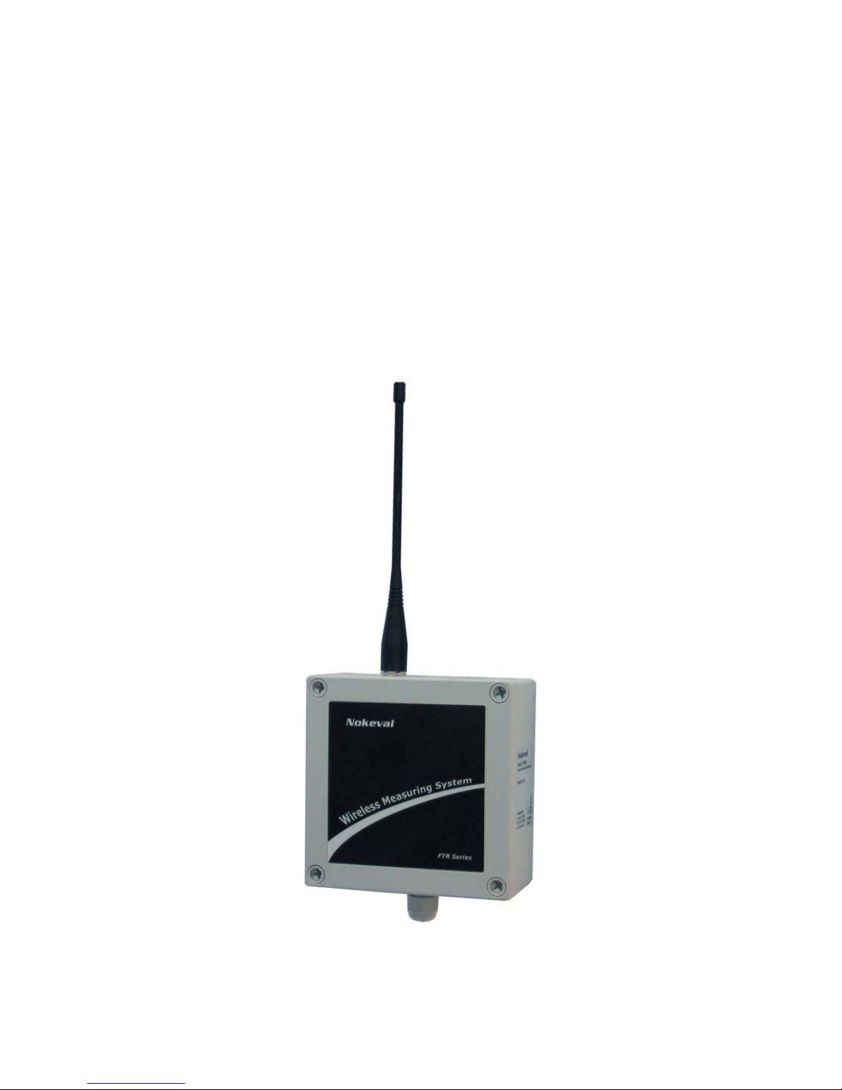
User manual
18.02.2008
V 1.06
FTR970-PRO
RADIO RECEIVER WITH LOGGER
Nokeval
Page 2
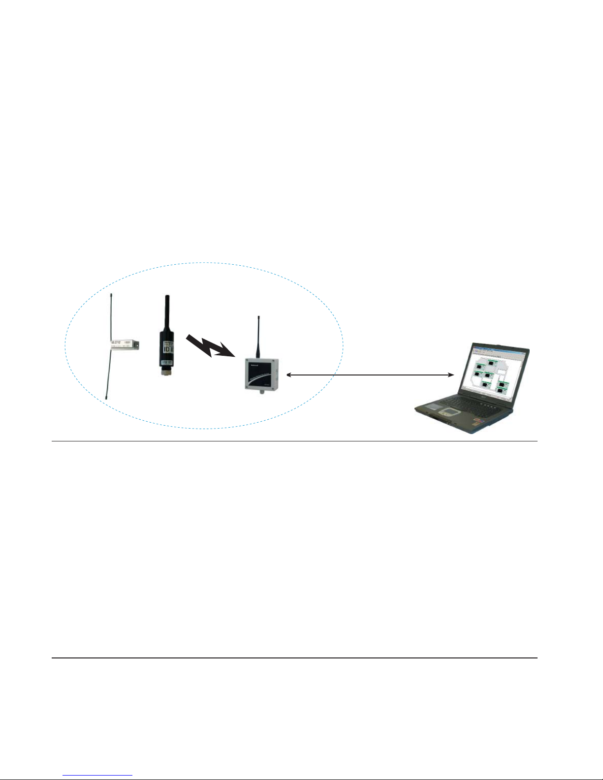
RS-485 or RS-232
PromoLog
2
FTR970-PRO is radio data receiver with data logging used with Nokeval MTR and FTR series radio
transmitters. Device can receive, unpack and buffer data packets into its memory from transmitters. It identifi es automatically type of a transmitter, so it can be used simultaneously with different
transmitters and with different transmit periods. FTR970-PRO uses license free frequency range of
433.92 MHz, so it can be used freely in areas where this so called ISM-frequency range is allowed,
covering almost whole of Europe.
Receiver can be connected to computer using either RS-485 or RS-232 bus and it needs an application program (PromoLog), which fetches processed data from the receiver’s memory.
Nokeval SCL or Modbus RTU protocols are used for data transfer. When RS-485 is used there can
be several FTR970-PRO devices on the bus and they can be positioned to cover larger receive area.
Receiver has four diagnostics leds and it needs operating voltage between 8..28 VDC.
Manufacturer
Nokeval Oy Tel +358 3 3424800
Yrittäjäkatu 12 Fax +358 3 3422066
FI-37100 www.nokeval.com
Finland Sales: [email protected]
Technical support: [email protected]
Contents
General ....................................................................................................................................... 2
Installing ..................................................................................................................................... 3
Settings ...................................................................................................................................... 8
Use with PromoLog .................................................................................................................... 11
Channels .................................................................................................................................... 17
Realtime data buffer ................................................................................................................... 20
Flash ........................................................................................................................................... 23
SCL protocol ............................................................................................................................... 27
Modbus protocol ......................................................................................................................... 28
Nopsa language ......................................................................................................................... 31
Applications ................................................................................................................................ 36
Technical data ............................................................................................................................ 37
GENERAL
Page 3
1 2 3 4
+
-
+ - D1 D09V
RS RF
USB
5 6 7
- RxD TxD
Power LED
J11
J7
Installation method
Best coverage is achieved when receiver has line of sight to the transmitters. Every obstacle between the devices will attenuate the signal and thus decrease range. On the other hand metal planes
will cause refl ections which can in some cases increase the range.
3
INSTALLING
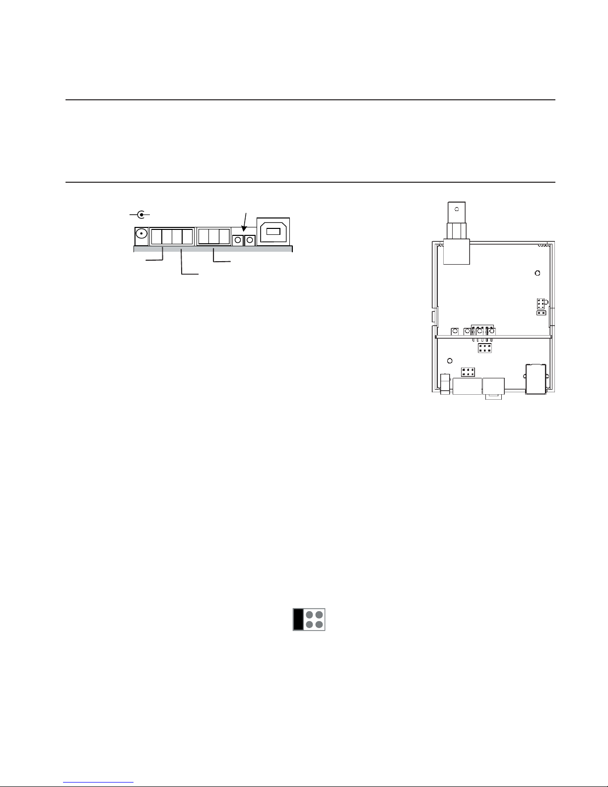
Device can be connected using either RS-485 or RS-232 buses. Each
of these is described in its own subchapter. Power supply connections
are also described separately in each subchapter.
USB bus can be used in case that the standard cable gland is replaced
by large one (not delivered). If it’s desirable to use either RS-485 or
RS-232 buses the device must be jumpered accordingly.
Connections
Power
The supply voltage 8...28 VDC is connected using 1.3 mm DC jack (centre connector positive) or
by using detachable screw post connector terminals 1 (+) and 2 (-). Both supply voltage connectors are internally connected. The receiver is protected against wrong polarity of the supply voltage. The supply voltage’s negative terminal is also used as ground for RS-485 and RS-232.
RS-485
When used with RS-485 bus jumper J11 has to be set according to following picture.
Device needs 8...28 VDC power supply which is connected either with 1.3mm DC-jack, with
positive center pole, or with terminal connections 1 (+) and 2 (-). DC-jack and terminal connector is connected in parallel. Device is protected against wrong polarity of power supply.
RS-485 can be easily added to computer using Nokeval DCS770 or DCS771 USB – RS-485 converter or RCS770 USB/RS-232 – RS-485 converter. RS-485 is connected to terminal connections 3
(D1), 4 (D0) and 2 (Gnd). Wrong connection of polarity doesn’t harm the device.
Antenna connection
Antenna is connected to device’s BNC connector. Antenna is fi rst pushed into the BNC connector
by aligning it with two guide posts after which it is turned 90 degrees clockwise.
RS485
RS232
Power supply
8...28 VDC
Page 4
4
Termination
Off
On
2-wire-485
Yes
No
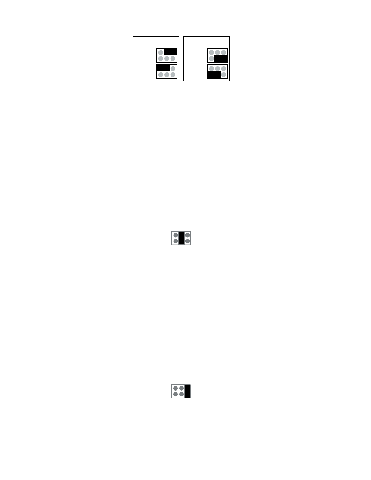
Settings for jumper J7
If RS-485 bus master has ground connection available, then jumper called ”2-wire-485” has to be in
position ”No”. If master lacks the connection, then potential equalization has to be done via D1- data
line by putting the jumper to position ”Yes”.
Last device on bus should have termination jumper on. It makes AC-termination for the line, which
means that there is 1nF capacitance and 110 ohm resistance in series between the lines.
Maximum length for the bus is 1km, and it allows 32 devices, more devices can be connected by
using repeaters.
RS-232
When used with RS-232 bus jumper J11 has to be set according to following picture. Jumper J7 has
no effect when RS-232 is used.
Device needs 8...28VDC power supply which is connected either with 1.3mm DC-jack, with
positive center pole, or with terminal connections 1 (+) and 2 (-). DC-jack and terminal connector is connected in parallel. Device is protected against wrong polarity of power supply.
RS-232 bus is not recommended because it is easily disturbed by EMC and maximum cable length
is only 15m in good conditions. RS-485 is recommended for longer ranges.
USB
USB bus can be used if the standard cable gland in the enclosure is replaced by larger one (not
delivered) or circuit board is installed into a customer’s enclosure.
When used with USB-bus jumper J11 has to be set according to following picture. Jumper J7 has
no effect when USB is used.
Device is powered from USB, but if the device should function when computer is turned off then external power supply is required. Device needs 8...28 VDC power supply which is connected either with
1.3mm DC-jack, with positive center pole, or with terminal connections 1 (+) and 2 (-). DC-jack and
terminal connector is connected in parallel. Device is protected against wrong polarity of power supply.
Page 5
PRO
Radio
Memory
Error
J11
J7
1 2 3 4
+
-
+ - D1 D09V
RS RF
USB
5 6 7
- RxD TxD
Power LED
5
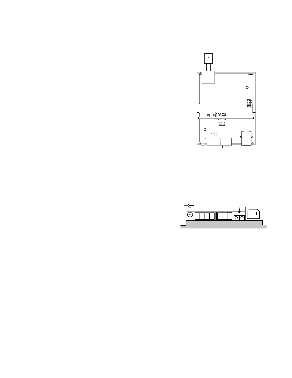
Indicator lights
Indicator lights
PRO: Means that device is operating.
RADIO: Means that device is processing serial communication command.
MEMORY: Means that device is writing data to fl ash memory.
ERROR: When power is applied to the device fi rst time error is light almost certainly, since the real time clock is out
of time in device. This error disappears when new time is
set to clock either automatically with PromoLog or manually with MekuWin. Note! In case that fl ash logging is disabled the time loss of real time clock does not lit error led.
Other than above this normally means that there is some
error. Meku monitor will give more descriptive error information. Possible error causes are: fl ash memory broken,
radio coprocessor not responding, real time clock circuit
not responding or real time clock time has been lost, or
EEPROM memory has been cleared.
If the error is caused by EEPROM memory, then error goes
off when new settings are saved to EEPROM.
If reason is that real time clock has lost time, error is continuously on, until new time is set to device.
All other errors will be automatically cleared if the reason
for error disappears, but if error light is on continuously
and cause of error is not some of the above mentioned
then the device must be sent for service.
Side indicator lights
RS: Informs about internal communication of device. This
should blink constantly.
RF: Informs about received radio packets. This light should
blink randomly depending on the number of radio transmitters within range.
Behind: Power led is positioned behind the two lights, and
it lights if the device is powered. This light is visible when
viewed directly from the front.
Page 6
6
Installing drivers when using USB
USB interface circuit needs two drivers for PC. First of them opens communication for the USB and
the other generates virtual serial port.
When PromoLog is installed on the computer it also installs these drivers automatically, but if
PromoLog is not installed then you can follow instructions below to install the drivers.
Drivers can be installed either from Nokeval Software CD or latest drivers can be downloaded directly from the web site of interface circuit manufacturer www.ftdichip.com (Drivers, FT232BM). This
install guide describes the installation from the CD, but it mostly applies with downloaded drivers
too.
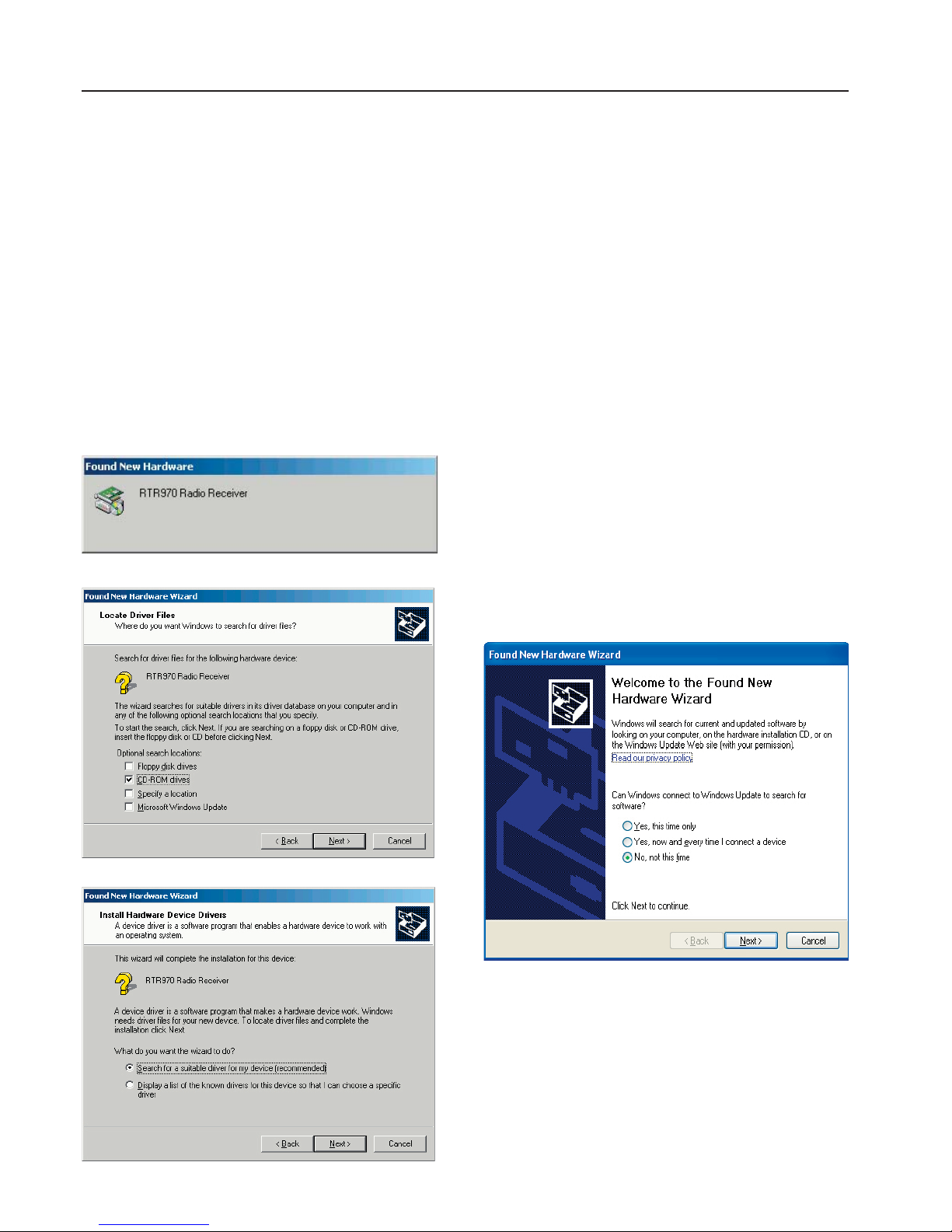
Insert Nokeval Software CD in the CD drive and plug the device to the PC. Windows should automatically notice the device and start the installation.
Installation for windows 2000 Installation for windows XP
First you get prompt to search for the drivers
from windows updata, if you have internet
connection available selet “Yes this time only”
and drivers will be installed automatically. Do
this for both drivers.
If you dont have internet connection available
do the following.
Page 7
7
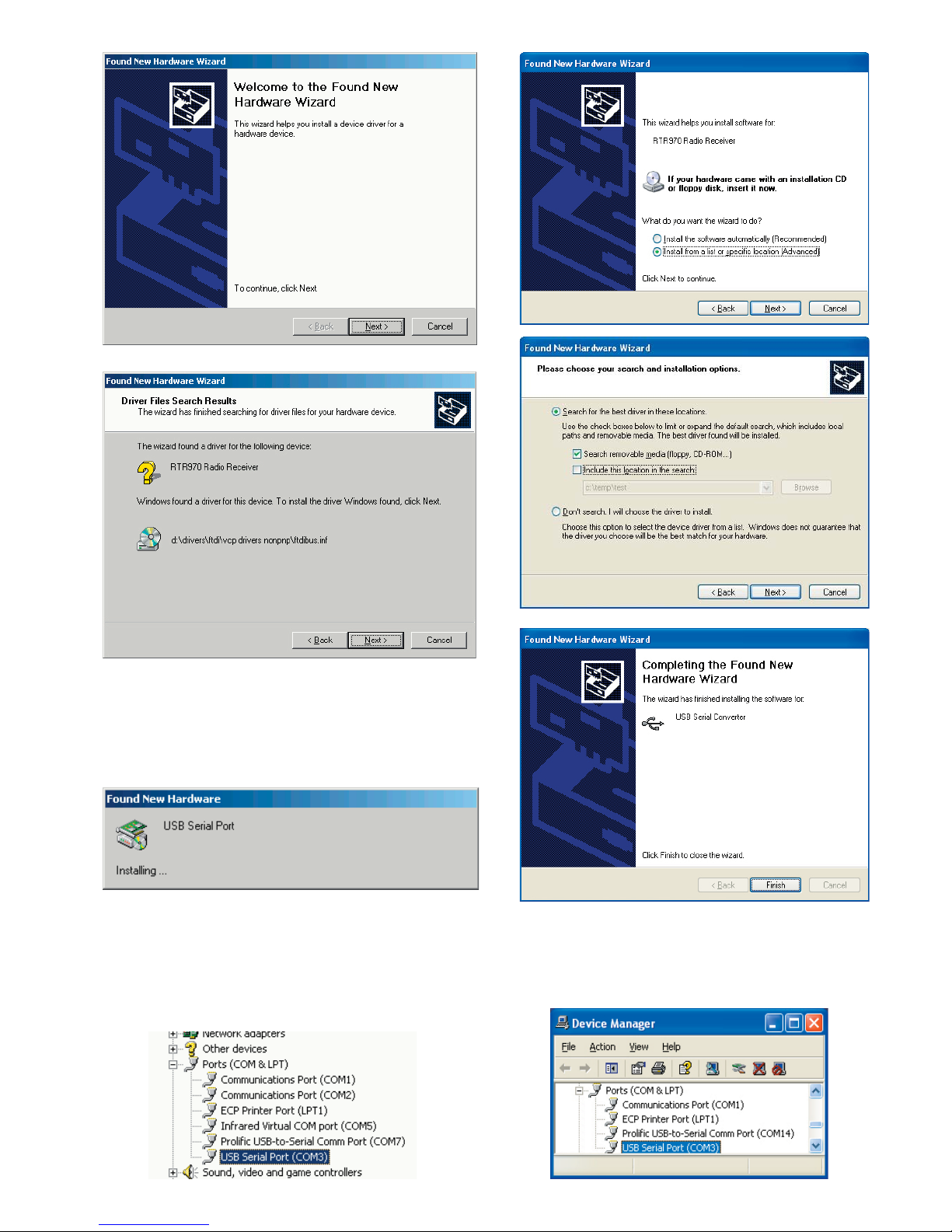
After USB bus driver ftdibus.inf has been installed, Windows will begin installation of virtual
port driver, which enables FTR970-PRO to look
like regular serial port, for example COM3.
Finally one must fi gure out on which COM-port
the device was attached. Open Control Panel/
Hardware/Device Manager. Open ports from the
device tree, and there should be USB Serial Port
in some of the COM ports.
Repeat this procedure for other driver (usb
serial port). And fi nally check from device
manager in which com port device was
detached.
Page 8
Realtime
Channels
Other periodic
Sporadic
Unknown
Logger
Channels
Other periodic
Sporadic
Unknown
Channel
interval [s]
Flash erase
Clock
Clock
Run
Year
Month
Day
Hour
Min
Sec
Ch1
ID
Type
Linearization
Alarm Group
Reading
Battery
Signal
Age [min]
Serial
Mode
Baud
Bits
Address
Conf
Serial
Channels
Logger
Realtime
Channels
Timeout [min]
Count
Ch1
Ch2
Ch3
Ch4
Ch5
Ch6
Ch7
Ch8
Ch9
Ch10
...
Ch90
8
SETTINGS
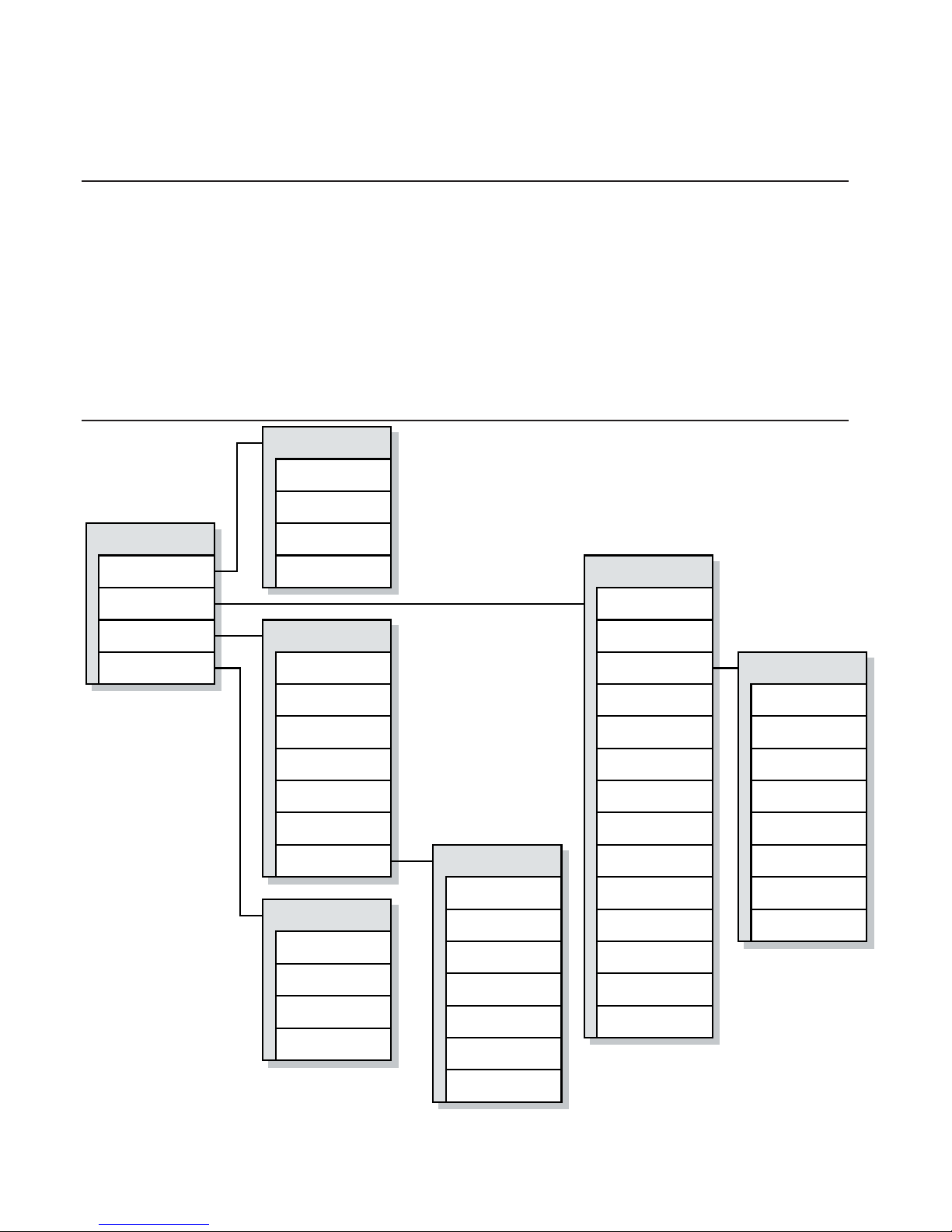
Communication settings
Settings for the device are done with PC using Mekuwin confi guration software. Mekuwin has its
own instruction manual.
Default settings for serial communication are:
• baud rate 115200
• protocol SCL
• bits 8N1
• address 0
Men
Page 9
Serial
Mode
Baud
Bits
Address
Jumper for
clearing settings
9
Serial submenu
Mode
Setting for serial mode.
• SCL slave: Nokeval SCL protocol
• Modbus slave: Modbus RTU protocol
Baud
Setting for baud rate.
• 1200, 2400, 4800, 9600, 19200, 38400, 57600, 115200, 230400
Bits
Setting for bits.
• 7E1, 8N1, 8E1, 8O1, 8N2
Note! SCL protocol always uses 8N1 and Modbus RTU uses commonly 8E1.
Address
Setting for serial address.
Allowed SCL addresses are 0..123. Allowed Modbus RTU addresses are 1..247.
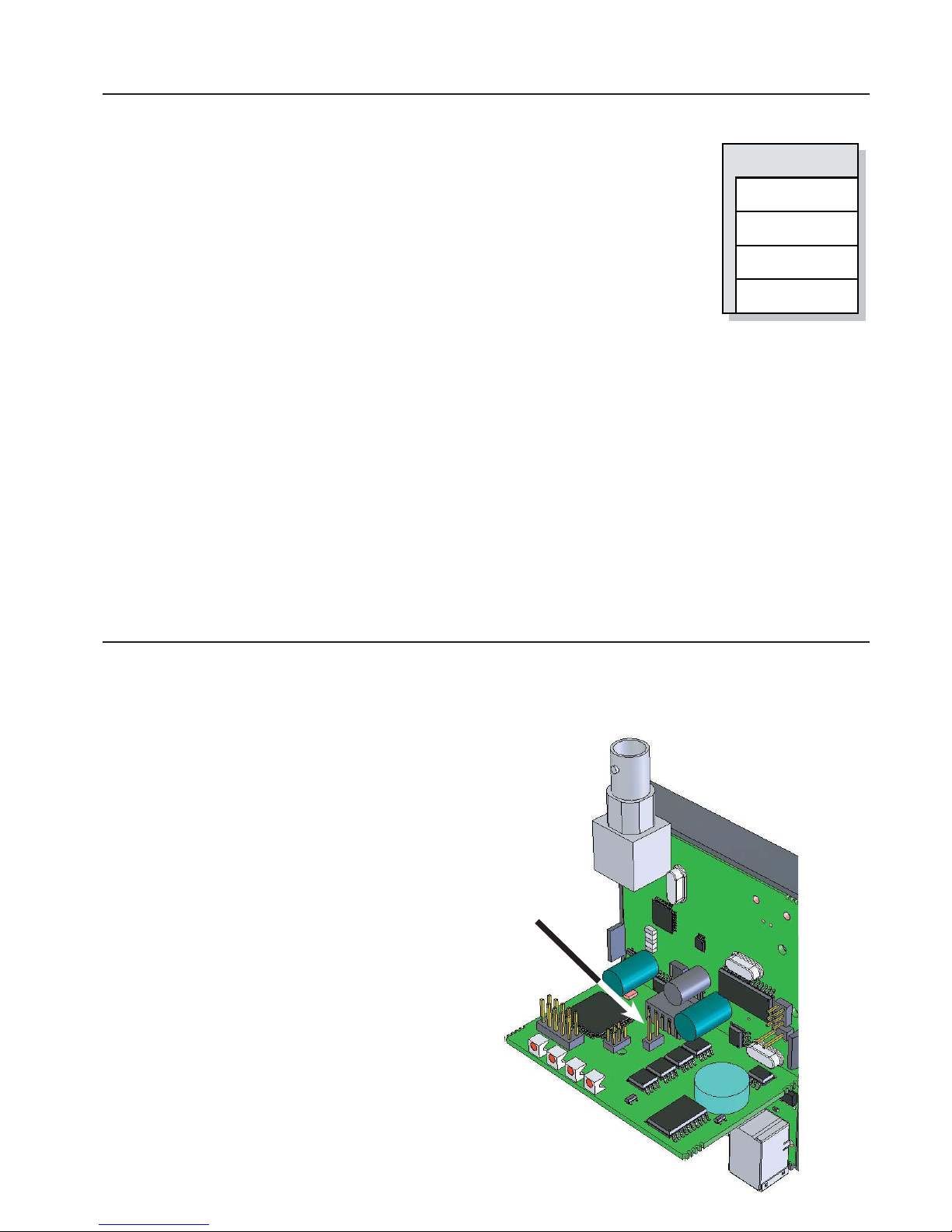
Resetting serial communication settings
In case serial settings are for some reason not known, they can be reset by setting jumper in the
position indicated by the following picture when the device is powered up.
Settings will be cleared as follows:
• baud rate 115200
• protocol SCL
• bits 8N1
• address 0
Page 10
10
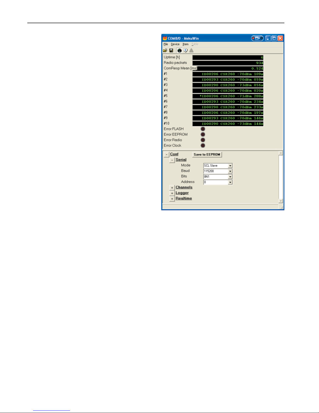
Meku monitor shows, how long the device has
been powered on, how many radio packets has
been received, and shows the mean latency for
serial communication.
Also 10 most recently received radio packets are
shown, which helps confi guration and troubleshooting. Monitor shows device ID, type, signal
strength and also how long time since reception.
Asterisk before line indicates the most recent
packet.
Signal strength -100dBm is just above noise and
about -65dBm is the maximum signal strength.
At the bottom there are ”Error” lights, which indicate where exactly there is error in device if any.
If any of these are lit, then also the front panel
error light is lit.
In all error conditions it is advisable to reboot the
device and check if the error condition persists.
Error lights
Meku Monitor
Error FLASH: Indicates that fl ash memory circuitry is malfunctioning. If the error won’t go off
then the device must be sent for service.
Error EEPROM: Indicates that device settings have been cleared, because of an error. Make
new settings and press ”Save to EEPROM”, which clears the error.
Error Radio: Indicates that radio coprocessor is malfunctioning. If the error won’t go off then
the device must be sent for service.
Error Clock: Indicates that real time clock circuitry is unreachable or time has been lost. If
error don’t go off by setting new time to the device then the device must be sent
for service.
Flash and clock errors dont harm other functions of the device, if fl ash and packetbuffers are not
needed.
Page 11
11
USE WITH PROMOLOG
Creating new serial interface
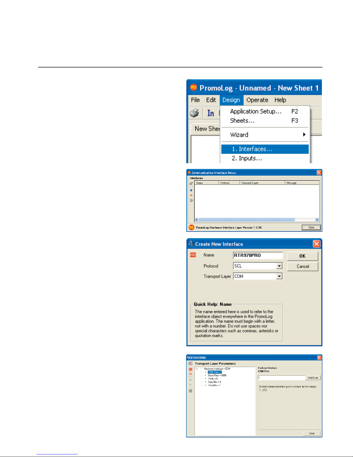
New serial connection can be created by choosing ”1. Interfaces” from Design menu. This will
open communication interface setup dialog.
Click blue plus button from the dialog to create
new serial interface.
Write a name for the interface and set protocol
to correspond settings in the device. Device supports SCL and Modbus RTU protocols. After settings are done press OK. Now there is a new
row in the previous window which represents the
newly created serial interface. Double click the
row to change the settings for the interface.
Transport layer can also be USB, if the device is
connected via USB to computer. In that case in
next phase choose the serial number of the device instead of the COM port.
Choose the correct COM port in the parameter
editor. Autoscan function scans all available COM
ports in the computer, which is helpful if you don’t
already know at which port the device is connected. If you’re using USB the COM port number
should be 3 or higher.
Set baud rate and data parity to correspond device settings. Factory setting for the device is
115200 baud.
PromoLog settings
Page 12
12
Creating new radio receiver unit
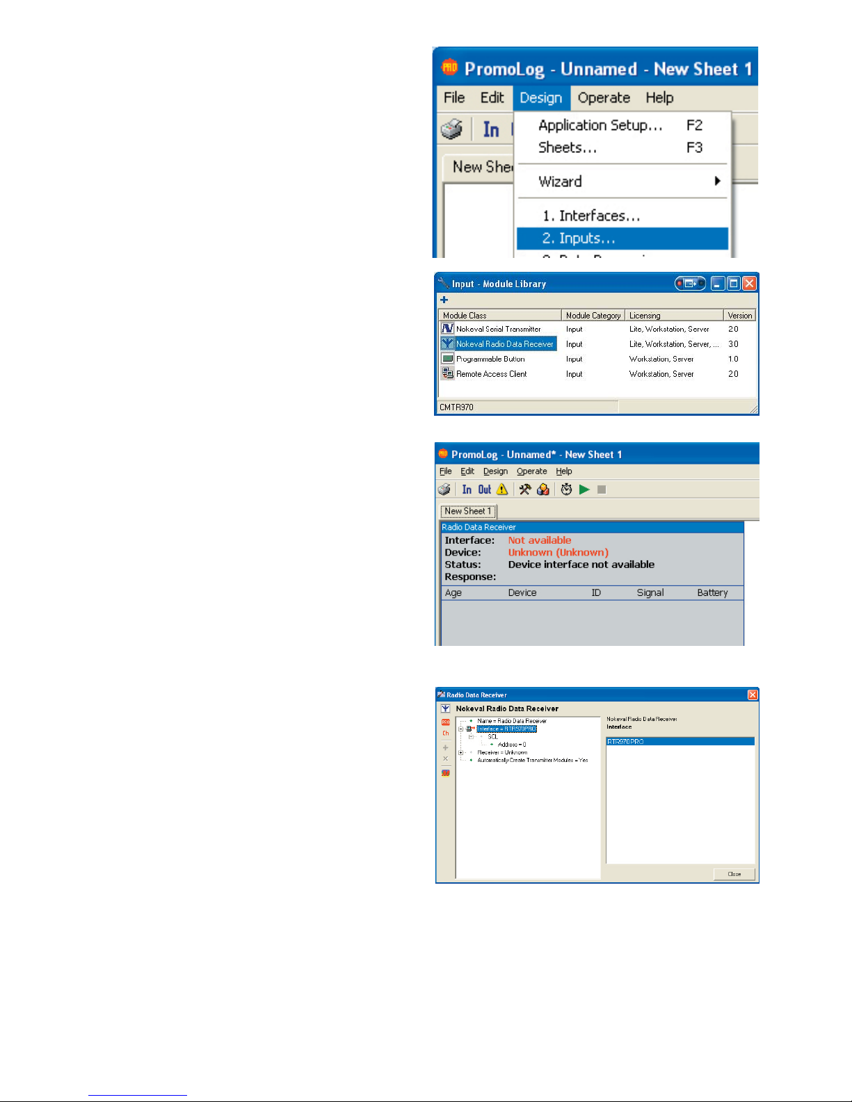
Choose ”2. Inputs” from the Design menu. This
opens input module library.
Create new ”Nokeval Radio Data Receiver”
module by dragging it on the active sheet. You
can also press the blue plus button or double
click the module name.
Double click the module on sheet to open parameter editor for it.
Choose recently created serial interface to Interface item. Check also from under Interface that
serial address corresponds device settings. You
can close the window.
Page 13
13
Module list button
Stop button
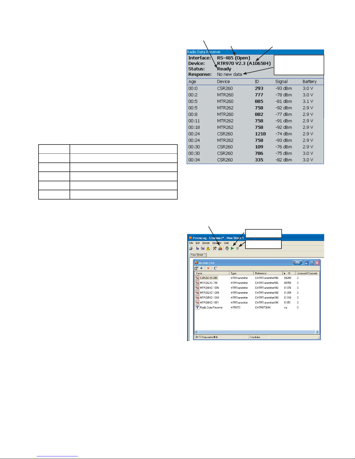
Module usage
Nokeval Radio Data Receiver module doesn’t
need any other than serial settings, which were
just made.
Nokeval Data Receiver module is split in two
sections. Upper section consists of status information of serial interface and receiver unit.
Lower section shows most recently received
data packets.
PromoLog gets new information from device only
when application is in running state.
Explanations for lower section columns:
Column Description
Age Time from receive
Device Type of the device
ID ID number of the device
Signal Received signal strength
Battery Battery voltage of the device
Adding new transmitter on screen
Press start button and module list button to start
the application and to open the module list window.
When application is running Nokeval Radio Data
Receiver module automatically adds all detected
transmitters on the list.
Some of the settings are disabled when application is running, therefore its recommended
that when all the transmitters are on the list, the
application is stopped before application building
is continued.
Device type and
serial number
Interface name
and state
Response from
the device
Device
state
Start button
Page 14
14
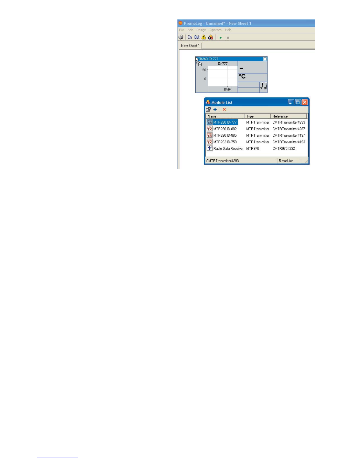
Transmitters can be added on a sheet by dragging them, clicking blue plus button or double
clicking them.
See PromoLog user manual for more information
about data manipulation and representation.
Page 15

15
Quick setting guide for device
FTR970-PRO supports two different methods for saving normal periodic transmitter data packets to
its fl ash memory: every packet separately or interval logging. Default setting is every packet separately.
Every packet separately
If it’s ok to save all radio packets to fl ash memory, then the device works with PromoLog with default settings. Drawback of this approach is that every radio packet uses up fl ash memory and thus
memory will fi ll up faster and oldest records gets overwritten.
Memory fi ll rate can be approximated using formula 150000*I/N, where I is transmit period and N is
the number of transmitters. For example, if there are 10 devices in range, which all transmit once in
every 60 seconds: memory fi ll rate is 150000*60/10 = 900000s = 10 days. If this is not enough then
transmit period can be set longer or the receiver changed to interval logging mode.
Device works this way with factory settings. Device can be set back in this mode using Mekuwin by
setting “Channel Interval “ to 0 from Logger submenu and setting “Channels”, “Other periodic” and
“Sporadic” settings on.
Interval logging
Interval logging means that at certain period device will save user selected transmitters to fl ash
memory as one record. Logging interval is freely selectable and thus it affects the memory fi ll rate.
Selected transmitters are chosen to be channels under channels submenu by using MekuWin program. Number of transmitters is entered to “Count” setting. ID number for the fi rst device is entered
to ID setting under Ch1 submenu. If the transmitter is of type MTR262, MTR264 or MTR265 and the
sensor is thermocouple, then the type of the element has to be entered in “Linearization” setting.
Otherwise the setting is left as None.
Channels setting is selected from the Logger submenu (so that chosen channels go to fl ash memory), and “Channel Interval” setting is set to chosen logging period in seconds, with maximum being
65535 seconds.
Suitable logging period can be approximated by using formula T*(7+6*N)/2000000, where T is wanted fi ll rate in days and N is the number of channels. For example, 10 transmitter are going to be
logged for 30 days: Channel Interval=30*(7+6*10)/2000000 = 0.001 days = 87 seconds.
Page 16

16
End of basic user part of the manual.
Start of expert user part of the manual.
Page 17
Ch1
ID
Type
Linearization
Reading
Battery
Signal
Age [min]
Channels
Timeout [min]
Count
Ch1
...
Ch90
17
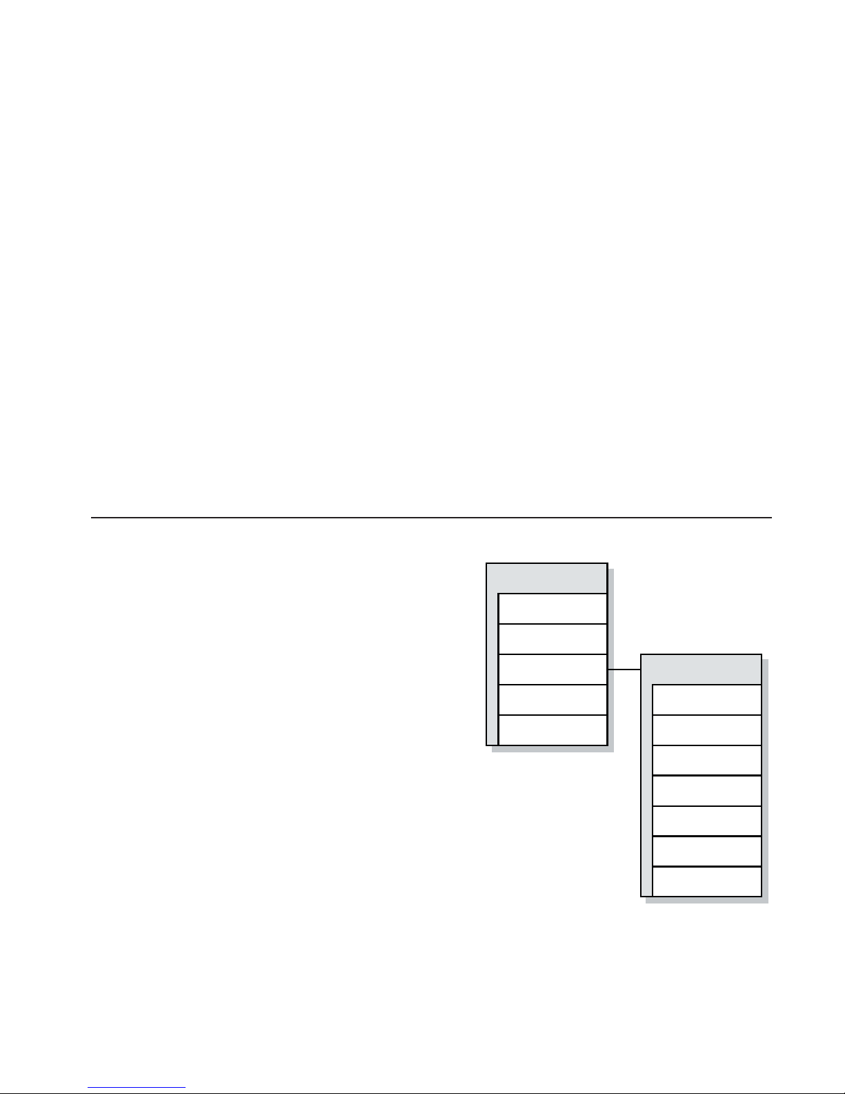
Device processes data in 3 different ways, one of which is channels.
Device can handle 90 channels simultaneously. Channel is a real time data container, which consists of one fully processed wireless transmitter. Some transmitter types can not be handled as
channels. Every transmitter whose measurement result can be expressed as a single numeric value
can be a channel.
Following devices can be channels:
MTR260, MTR262/FTR262, MTR264, MTR265, MTR165, FTR860 and CSR260.
Following devices can not be channels:
CSR264, KMR260
Channel contains all available information of a transmitter: Value, device type, ID, battery voltage,
signal strength and information how long has passed since last data reception. When confi guring
device as a channel, only the device ID needs to be known, other information updates automatically.
However used thermocouple type must be confi gured when using devices which are confi gured to
measure with thermocouples.
Channels submenu
Timeout
Tells how many minutes have to pass since last
reception until it is determined that device is not
transmitting and its value is set to NaN (Not A Number).
For Ex. If Timeout = 10 min then channel value is
set to NaN when more than 10 minutes but
less than 11 minutes have passed since
last reception.
Count
Tells how many channels are used (0..90)
ID
Identifi cation number of the transmitter (1..65535).
ID 0 means that channel is not in use.
Type (updated automatically)
Tells the type of the device. For ex. MTR260.
Linearization
Used thermocouple linearization, this setting is visible only if device in question can measure temperature with thermocouples but cannot perform the necessary linearization by itself.
(MTR262/FTR262, MTR264, MTR265)
Possible thermocouple types are: B, C, D, E, G, J, K, L, N, R, S, T, or None in case thermocouple is
not used.
CHANNELS
Page 18

18
Reading (updated automatically)
Channel reading
Battery (updated automatically)
Battery voltage of the device
Signal (updated automatically)
Received signal strength.
(About -100dBm = barely receivable, -65dBm = maximum strength)
Age (updated automatically)
Tells how many minutes has passed since last reception. Note! This value is updated once in a minute for all channels simultaneously, which means that value can increment any time after 1-60s after
packet reception.
Serial commands
In case PromoLog is not used for reading data from the device, following commands can be used
to read data.
Following commands are usable for reading channel information. Different protocols are fully explained in their own chapters, here is a quick summary of each protocols available commands.
Nokeval SCL protocol
MEA CH Read channel reading
Modbus RTU protocol
03 (Read Holding Registers) Readings mixed with settings
04 (Read Input Registers) Read readings and other channel information either as fl oat-
ing point or integer number.
Modbus register map in Modbus chapter.
Nokeval Nopsa commands (transport protocol SCL or Modbus RTU)
2/0 (Out value request) Read channel reading
2/1 (Out resource request) Read channel meta information (name, data type)
4/32 (Channel count) Channel count
4/33 (Changed channels) Bit fi eld of changed channels after last read operation
4/34 (Read channels with index) Read all channel information of certain channel
4/35 (Read next channel) Read all channel information of next changed channel
Data structure
Data structure of Nopsa commands (4/34, 4/35).
ID 2 bytes, 16bit integer, least signifi cant byte fi rst.
Reading 4 bytes, IEEE fl oating point number.
Type 1 byte, integer. See following table for types.
Signal strength 1 byte, integer. Subtract 127 and result is in dBm.
Battery voltage 1 byte, integer. Divide with 10 and result is in Voltage.
Page 19

19
Table for possible device types
Type Value
MTR260 0
MTR262/FTR262 2
MTR264 4
MTR265 5
MTR165 6
FTR860 7
CSR264S 8
CSR264L 9
CSR264A 10
CSR260 11
KMR260 12
Machine to machine communication
Channel information can be used so that some other device is used to read information and further
process it.
Nokeval 7470 serial transmitter can read maximum of 4 channels via serial communication using
Nokeval SCL protocol and then convert these into mA- or V-signals.
See chapter Applications
Page 20
Realtime
Channels
Other periodic
Sporadic
Unknown
20
Device processes data in 3 different ways, one of which is real time data buffer. This data buffer is
completely independent of other functions of the device. Real time data buffer preserves most recent
radio packets until PC-program has time to read them.
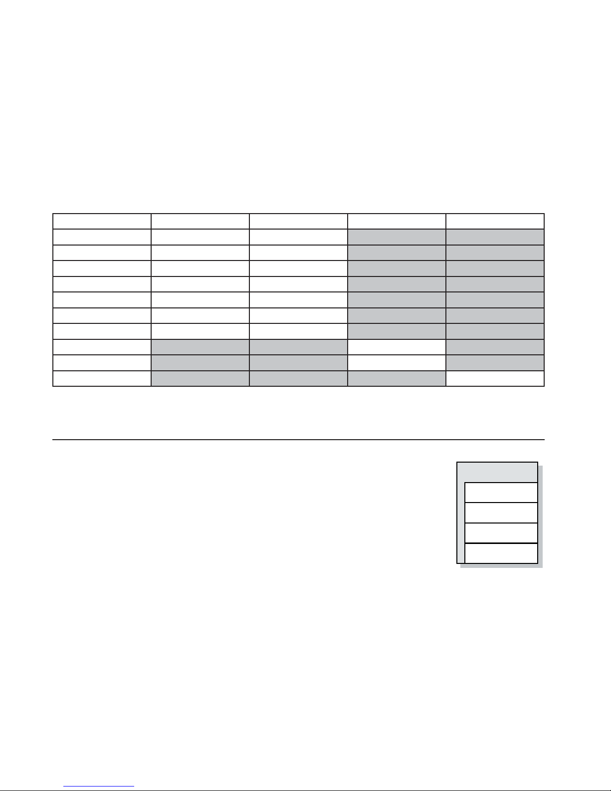
Data buffer has room for 90 packets. Menu has a setting called “Realtime” which dictates which kind
of data is saved to this buffer.
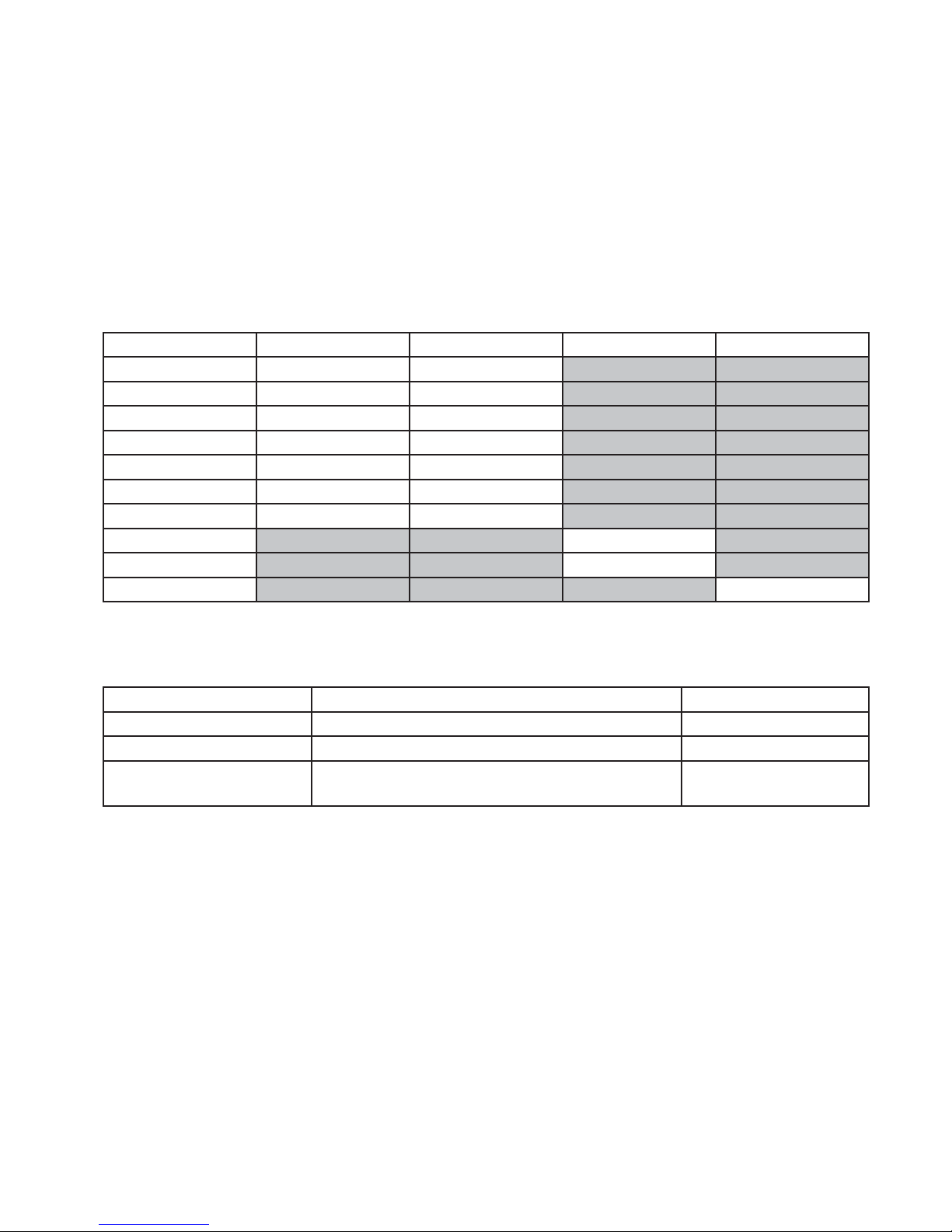
Table how data is saved to the real time data buffer depending on device type and settings.
Channels Other periodic Sporadic Unknown
MTR260 Processed Processed
MTR262/FTR262 Processed Unprocessed
MTR264 Processed Unprocessed
MTR265 Processed Unprocessed
MTR165 Processed Processed
FTR860 Processed Processed
CSR260 Processed Processed
Unprocessed
KMR260 Unprocessed
X Unprocessed
Note! Cells in gray are not possible options.
Realtime submenu
Channels
Choose whether channels are saved in real time data buffer.
Channels are devices whose IDs have been confi gured in the channel
table in menu and are of type which can be used as channels.
See previous table.
Other Periodic
Choose whether devices, which could be channels but are not confi gured
in channel table in menu, are saved in real time data buffer.
Sporadic
Choose whether devices, which could not be channels, are saved in real time data buffer.
These devices are mostly kind of devices which send burst data when stimulated, and not periodically like the devices that can be classifi ed as channels. For these purposes the FTR970-PRO has
also so called burst trap buffer, which removes multiple copies of burst data.
Unknown
Choose whether devices which are unknown (those devices which are designed after FTR970-PRO
software version) are saved in real time data buffer.
REALTIME DATA BUFFER
Page 21

21
Serial commands
In case PromoLog is not used for reading data from the device, following commands can be used to
read data from device.
Following commands are usable for reading channel information. Different protocols are fully explained in their own chapters, here is a quick summary of each protocols available commands.
Nokeval SCL protocol
Reading with Nopsa command over SCL protocol.
Modbus RTU protocol
Reading with Nopsa command over Modbus RTU protocol.
Nokeval Nopsa commands (transport protocol SCL or Modbus RTU)
4/0 (Buffer info) Read buffer size and current write position
4/1 (Find oldest from buffer) Move read position to oldest entry in buffer
4/2 (Find newest from buffer) Move read position to newest entry in buffer
4/3 (Read buffer with index) Read specifi c data entry from buffer
4/4 (Read next from buffer) Read data entry from buffer and move read position to next
4/5 (Reread last) Returns last read operation contents
Preferred way to read buffer is by using commands 4/4 and 4/5. First read next from buffer with command 4/4 and in case of serial transmission error last read entry is asked again by command 4/5.
Commands return also read position and lap counter.
Command 4/3 is only preferred in case the transfer layer in the reading program is queued, which
means that multiple commands are input to queue before response arrives. In that case when serial
transmission error happens then buffer reread can not be used, so it’s safer to keep track of read
index implicitly. This method is normally not preferred.
Buffer is organized as a ring buffer and when read position reaches write position which means there
are no new data, then commands return empty response packet.
Data structure
Data structure in buffer is following. Note! This presents only the actual data in data fi eld, other parts
of Nopsa packet is explained in chapter Nopsa. Device can return 2 different packets, both of which
are below.
Data type STRUCT
Struct type 0 (raw radio data packet)
Device type 1 byte, integer, see table on page 19
Signal strength 1 byte, integer. Subtract 127 to get result in dBm.
Bytes + battery 1 byte, 3 msb data bytes, 5 lsb battery voltage.
Divide battery by 10 to get result in volts.
Data bytes 0-7 bytes. Information is dependent on device type.
Page 22

22
Data type STRUCT
Struct type 1 (processed radio data packet)
Device type 1 byte, integer. See table on page 19
Signal strength 1 byte, integer. Subtract 127 to get result in dBm.
Bytes + battery 1 byte, 3 msb data bytes, 5 lsb battery voltage.
Divide battery by 10 to get result in volts.
Result 4 bytes, IEEE fl oating point
Page 23
23
Device processes data in 3 different ways, one of which is fl ash memory write.
Device has 2 MB of fl ash memory for data recording. Data can be saved in fl ash memory in 3 different formats: processed, unprocessed and interval logged.
Interval logging is described in “Channel Interval” sub chapter.
Table how data is saved to fl ash memory depending on devices and settings.
Channels Other periodic Sporadic Unknown
MTR260 Processed Processed
MTR262/FTR262 Processed Unprocessed
MTR264 Processed Unprocessed
MTR265 Processed Unprocessed
MTR165 Processed Processed
FTR860 Processed Processed
CSR260 Processed Processed
CSR264 Unprocessed
KMR260 Unprocessed
X Unprocessed
Note! Cells in gray are not possible options.
Memory usage
Data type Bytes per entry Max entry count
Processed data 13 bytes 150000 entries
Unprocessed data 10..17 bytes (on average 16) 125000 entries
Interval logged data (7+N*6)/N bytes, in which N means logged
channel count
320000 entries
Memory is organized as a ring buffer. When memory starts to fi ll up then the oldest entries will be
overwritten in 64kB sectors, which means that 64kB of oldest data is cleared and then fi lled with
data, and when it fi lls up then another 64kB of oldest data is cleared and so on.
Memory fi ll rate can be calculated as follows. Let’s assume there are 30 transmitters whose transmissions are logged once in a minute. Memory fi ll rate would then be approximately 150000/(30/60s)
= 300000s = 83h. So memory would need to be read in under 83h so that no data is lost.
On the other hand, memory can last longer if data is interval logged say once in a 5 minute. In this
case data uses (7+30*6)/30 = 6.23 bytes per entry and memory fi ll rate would be approximately
(2000000/6.23)/(30/(5*60s)) = 3210000s = 891h = 37 days.
FLASH
Page 24
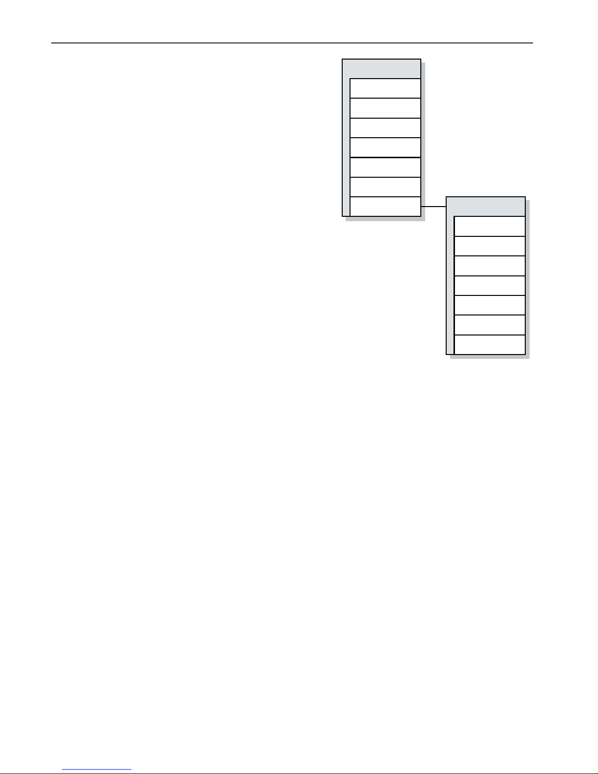
Logger
Channels
Other periodic
Sporadic
Unknown
Channel
interval [s]
Flash erase
Clock
Clock
Run
Year
Month
Day
Hour
Min
Sec
24
Channels
Choose if channels are to be saved into the fl ash
memory
Channels are devices whose IDs have been confi gured
in the channel table in menu and are of type which can
be used as a channel. See previous table.
Other periodic
Choose whether devices, which could be channels but
are not confi gured in channel table in menu, are to be
saved in fl ash memory.
Sporadic
Choose whether devices, which could not be channels,
are to be saved in fl ash memory.
Unknown
Choose whether devices which are unknown (those devices which are designed after FTR970-PRO software
version) are to be saved in fl ash memory.
Channel interval
This setting sets whether interval logging is on.
If setting is 0, interval logging is not in use. Any other value enables interval logging and sets the
interval time in seconds. Interval logging means that all channels are saved to fl ash periodically with
set interval. This is useful if the fl ash memory need to last as long as possible for given transmitter
count. Maximum value for this setting is 65535s.
This setting dictates only how channel data is saved in to the fl ash memory.
Flash erase
Flash can be erased with this if “clear settings” jumper is set, see page 9. If jumper is not set on
board, this won’t do anything.
Run
This setting is used to stop clock updates to Mekuwin menu, so that new time can be set.
Year, Month, Day, Hour, Min, Sec
These are used to update new time for the device. Maximum for the year is 2063. When new time
is set, “Save to EEPROM”-button near clock menu has to be pressed to update the clock. There is
about 1s delay on setting to the clock from the menu.
Logger submenu
Page 25

25
Serial commands
In case that data acquisition software PromoLog is not used for reading data from the device, then
following serial commands can be used to read data from the device.
Following commands are usable for reading fl ash memory. Different protocols are fully explained in
their own chapters, here is quick summary of each protocols available commands.
Nokeval SCL protocol
Reading with Nopsa command over SCL protocol.
Modbus RTU protocol
Reading with Nopsa command over Modbus protocol.
Nokeval Nopsa commands (transport protocol SCL or Modbus RTU)
4/16 (Read fl ash from location) Read data from given location
4/17 (Find time from fl ash) Give location from fl ash which has newer data than given
time
4/18 (Give fl ash write position) Give location where fl ash write is progressing
4/19 (Give fl ash size) Read fl ash size
4/48 (Clock set) Set new time for the device
4/49 (Clock fetch) Read time from the device
When reading the memory you have to read faster than what is maximum fi ll rate to be on the safe
side. Command which fi nds time from the fl ash also automatically give a safety margin to the write
position if needed. This safety margin is at least one full sector which means 64kB of data, since data
is always deleted as a full sector at a time.
Radio specifi cations require that no more than 4 data packets can be received in a second on average,
because otherwise duty cycle requirements would not be met. If data is written as unprocessed to
the memory, then memory fi ll rate would be 4x17=68 bytes/s maximum. Lets calculate 65535 bytes
/ 68 bytes/s = 963s = 16min. So if one sector of data is read faster than this then there is no way
that data is deleted before it can be read. In theory memory fi ll rate can be higher than this if interval
logging is used for high number of channels, with very tight interval, but that is not a very feasible
confi guration.
Page 26
26
Data structure
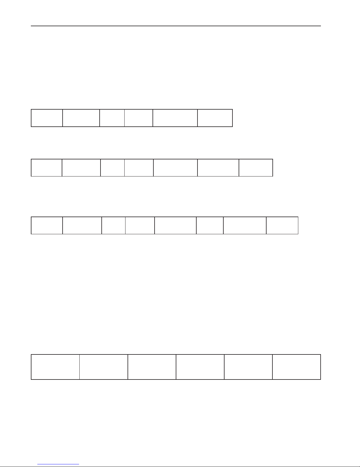
Data is saved to fl ash in the following format. Byte order is least signifi cant byte fi rst (little-endian)
Every packet has a header which informs where the packet footer is and also packet footer informs
where packet header is, so data is organized as a two way linked list.
There are 3 kinds of packets and every packet has a recognition byte which tell the type of a packet.
Processed data:
Length-1
1 byte
Time
4 bytes
0xA0
1 byteID2 bytes
Value / Float
4 bytes
Length-1
1 byte
Length gives size of the record including header and footer.
Unprocessed data:
Length-1
1 byte
Time
4 bytes
0xA1
1 byteID2 bytes
Device type
1 byte
Data
0-7 bytes
Length-1
1 byte
Data is dependent on device type and its not described in this manual. Device specifi c data is available on request if needed.
Interval logged data:
Length-1
1 byte
Time
4 bytes
0xA2
1 byteID2 bytes
Value / Float
4 bytes
ID
2 bytes
Value / Float
4 bytes
Length-1
1 byte
Interval logged data has ID-value pairs N times, and total length or record can not exceed 255
bytes.
Zero padding
Data can contain 0 size packets because there are sector synchronizations and write error fi xes. But
data packet which header and footer are both 0 is totally eligible and need no special rules, since it
can be processed with same jumping rules as normal packets.
Time format
Time is presented with 4 bytes, with following bit fi elds, least signifi cant byte fi rst.
msbit
Year
6 bits
00-63
Month
4 bits
1-12
Day
5 bits
1-31
Hour
5 bits
0-23
Minutes
6 bits
0-59
Seconds
6 bits
0-59
Page 27

27
SCL PROTOCOL
Nokeval SCL-protocol and commands are presented in separate SCL-manual, which can be downloaded from Nokeval web site. Device accepts following commands:
TYPE ?
Device returns its type and software version information.
SN ?
Device returns its serial number. For ex. “A123456”.
MEA CH x ?
Device returns last result from “measuring channel x”
N
Nopsa command, see chapter Nopsa-protocol.
Page 28

28
MODBUS PROTOCOL
Supported Modbus RTU commands:
• 3 Read Holding Registers: Read settings
• 4 Read Input Registers: Read result values
• 6 Write Single Register: Change settings
• 16 Write Multiple registers: Change multiple settings at once.
• 17 Report Slave ID: Device type information.
• 109 Meku: This is used by Mekuwin confi guration software.
• 110 Nopsa: This is used to transport Nopsa protocol on Modbus.
This device uses 7E1, 8N1, 8E1, 8O1 or 8N2 parity bits.
When settings are changed device will save settings instantly to confi guration EEPROM memory.
Maximum modbus packet length is 240 bytes. This affects maximum possible register count on commands 3, 4 and 16.
Command 17 return 0x11 <byte count> 0x00 0xFF, followed by for example “RTR970PRO V1.0
A123456”
If serial settings are changed, new settings will take effect only after cycling the device power, it
works this way so that all serial settings can be done.
Data types
• BOOL: On/off value. 0=off, 1=on. In lower (right hand side) byte.
• BYTE: 8-bit value. Only lower (right hand side) byte used.
• WORD: 16-bit value.
• ENUM: List of alternatives.
• FLOAT: 32-bit fl oat IEEE 754. Least signifi cant word fi rst, inside word most signifi cant byte fi rst.
• STRINGZ: Zero terminated string. In one modbus register data is presented as most signifi cant
byte fi rst.
Page 29
29
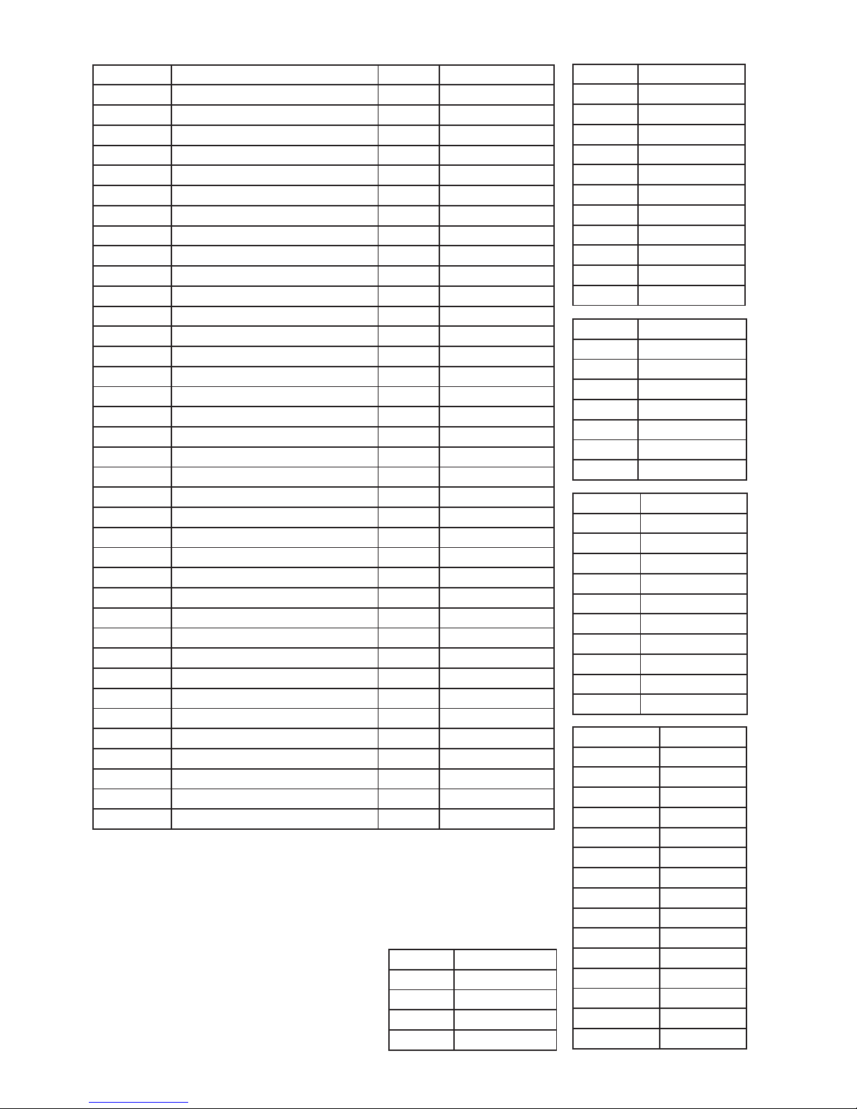
Holding registers
Register Name Type Values
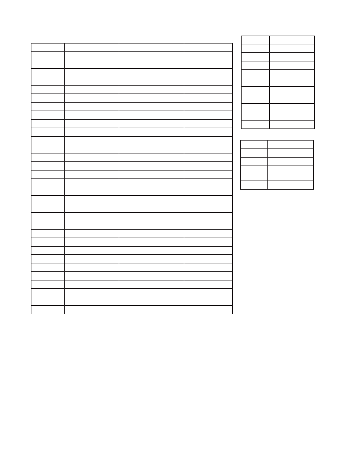
2000 Conf\Serial\Mode ENUM See table E1
2001 Conf\Serial\Baud ENUM See table E2
2002 Conf\Serial\Bits ENUM See table E3
2003 Conf\Serial\Address BYTE Unsigned 0...247
2015 Conf\Channels\Timeout [min] BYTE Unsigned 1...127
2016 Conf\Channels\Count BYTE Unsigned 0...90
2017 Conf\Channels\Ch1\ID WORD Unsigned
2018 Conf\Channels\Ch1\Type ENUM See table E5
2019 Conf\Channels\Ch1\Linearization ENUM See table E6
2021..2022 Conf\Channels\Ch1\Reading FLOAT Signed
2023..2024 Conf\Channels\Ch1\Battery FLOAT Unsigned
2025..2026 Conf\Channels\Ch1\Signal FLOAT Signed
2027 Conf\Channels\Ch1\Age [min] BYTE Unsigned 0...31
2028 Conf\Channels\Ch2\ID WORD Unsigned
2029 Conf\Channels\Ch2\Type ENUM See table E5
2030 Conf\Channels\Ch2\Linearization ENUM See table E6
2032..2033 Conf\Channels\Ch2\Reading FLOAT Signed
2034..2035 Conf\Channels\Ch2\Battery FLOAT Unsigned
2036..2037 Conf\Channels\Ch2\Signal FLOAT Signed
2038 Conf\Channels\Ch2\Age [min] BYTE Unsigned 0...31
…
3028 Conf\Logger\Channels BOOL
3029 Conf\Logger\Other periodic BOOL
3030 Conf\Logger\Sporadic BOOL
3031 Conf\Logger\Unknown BOOL
3032 Conf\Logger\Channel interval [s] WORD Unsigned
3033 Conf\Logger\Clock\Run BOOL
3034 Conf\Logger\Clock\Year BYTE Unsigned 0...63
3035 Conf\Logger\Clock\Month BYTE Unsigned 1...12
3036 Conf\Logger\Clock\Day BYTE Unsigned 1...31
3037 Conf\Logger\Clock\Hour BYTE Unsigned 0...23
3038 Conf\Logger\Clock\Min BYTE Unsigned 0...59
3039 Conf\Logger\Clock\Sec BYTE Unsigned 0...59
3040 Conf\Realtime\Channels BOOL
3041 Conf\Realtime\Other periodic BOOL
3042 Conf\Realtime\Sporadic BOOL
3043 Conf\Realtime\Unknown BOOL
All 90 channels are not presented here, but address for any given
channel can be calculated by using formula:
2017+(N-1)*11
Input registers are also mapped to starting at register address 5000
Table E3
Value Bits
07E1
18N1
28E1
38O1
48N2
Table E5
Value Type
0 MTR260
1 MTR262
2 MTR264
3 MTR265
4 MTR165
5 FTR860
6 CSR260
7 Unknown
Table E6
Value Linearization
0 None
1TcB
2TcC
3TcD
4TcE
5TcG
6TcJ
7TcK
8TcL
9TcN
10 TcR
11 TcS
12 TcT
Table E1
Value Mode
0 SCL Slave
1 Modbus Slave
Table E2
Value Baud
0 1200
12400
2 4800
3 9600
4 19200
538400
6 57600
7 115200
8 230400
Page 30
30
Input registers
Register Name Type Values
0..1 Ch1\Reading FLOAT (LSW, MSB) Signed
2..3 Ch2\Reading FLOAT (LSW, MSB) Signed
... ...
178..179 Ch90\Reading FLOAT (LSW, MSB) Signed
200..201 Ch1\Reading FLOAT (MSW, MSB) Signed
202..203 Ch2\Reading FLOAT (MSW, MSB) Signed
... ...
378..379 Ch90\Reading FLOAT (MSW, MSB) Signed
400..401 Ch1\Reading FLOAT (LSW, LSB) Signed
402..403 Ch2\Reading FLOAT (LSW, LSB) Signed
... ...
578..579 Ch90\Reading FLOAT (LSW, LSB) Signed
600..601 Ch1\Reading FLOAT (MSW, LSB) Signed
602..603 Ch2\Reading FLOAT (MSW, LSB) Signed
... ...
778..779 Ch90\Reading FLOAT (MSW, LSB) Signed
1000 Ch1\Reading WORD Signed
1001 Ch2\Reading WORD Signed
... ...
1089 Ch90\Reading WORD Signed
2000 Ch1\ID WORD Unsigned
2001 Ch1\Type ENUM See Table E5
2002 Ch1\Battery WORD Unsigned
2003 Ch1\Signal WORD Unsigned
2004 Ch1\Flags WORD See table E7
...
Measured values are available in 4 different word/byte order formats in registers below 1000.
All fl oats are 32-bit fl oat IEEE 754.
In registers 0..179 Least signifi cant word fi rst, inside word most signifi cant byte fi rst.
In registers 200..379 Most signifi cant word fi rst, inside word most signifi cant byte fi rst.
In registers 400..579 Least signifi cant word fi rst, inside word least signifi cant byte fi rst.
In registers 600..779 Most signifi cant word fi rst, inside word least signifi cant byte fi rst.
In registers 1000..1089 results of channels are presented using fi xed point notation with 1
decimal. In example integer 150 means 15.0.
Note! In case result is too old (older than time out in menu) or there are no result for a channel
then fl oat value is Quiet NaN ( 0x7FC00000 ) and word value is 0x7FFF.
Note! These registers are also mapped to holding registers so that input register 0 = holding
register 5000 and so on.
Table E7
Bits Bits
0..6 Age counter
[min]
7 Data changed
Table E5
Value Type
0 MTR260
1 MTR262
2 MTR264
3 MTR265
4 MTR165
5 FTR860
6 CSR260
7 Unknown
Page 31

31
NOPSA LANGUAGE
Nopsa is a command language which enables measurement data and confi guration data transfer.
Nopsa can be used to transfer data between devices or from host to device.
Nopsa needs some transfer layer protocol, which take care of addresses, transfer error management and packet length. Device supports Nopsa commands either on Nokeval SCL or Modbus RTU
protocols.
Supported Nopsa commands
1/0 (Type) Read device type
1/1 (Version) Read device version
1/2 (Serial number) Read serial number of the device
1/3 (Description) Read short description of the device
1/4 (Command set) Read command set number for the device
1/5 (Serial buffer size) Read serial buffer size
1/16 (Reset) Reset device
1/32 (Meku) Pass Meku confi guration commands to device
2/0 (Out value request) Read channel reading
2/1 (Out resource request) Read channel meta information (name, data type)
4/0 (Buffer info) Read buffer size and current write position
4/1 (Find oldest from buffer) Move read position to oldest entry in buffer
4/2 (Find newest from buffer) Move read position to newest entry in buffer
4/3 (Read buffer with index) Read specifi c data entry from buffer
4/4 (Read next from buffer) Read data entry from buffer and move read position to next
4/5 (Reread last) Returns last read operation contents
4/16 (Read fl ash from location) Read data from given location
4/17 (Find time from fl ash) Give location from fl ash which has newer data than given time
4/18 (Give fl ash write position) Give location where fl ash write is progressing
4/19 (Flash size) Read fl ash size
4/20 (Flash erase) Erases the fl ash memory fully
4/32 (Channel count) Read channel count
4/33 (Changed channels) Read bit fi eld of changed channels after last read operation
4/34 (Read channels with index) Read all channel information of certain channel
4/35 (Read next channel) Read all channel information of next changed channel
4/48 (Clock set) Set new time for the device
4/49 (Clock fetch) Read time from the device
Page 32

32
Transport protocol SCL
When Nopsa packets are transported on SCL data is converted to hexadecimal notation (0-9 and
A-F). One Nopsa byte will become 2 bytes. No spaces between characters. Packet starts with SCL
command N and a space.
ID
’N’ ’ ’ Nopsa-packet in hexadecimal ETX BCC
Response is transferred also same way in hexadecimal, but N command is not appended.
ACK Nopsa-response in hexadecimal ETX BCC
Transport protocol Modbus RTU
Command function 110 (0x6E) is reserved for Nopsa commands in Modbus free command area.
After function code there is one byte which informs Nopsa packet length.
ID 0x6E Length Nopsa-packet CRC
Response is in same format
0x6E Length Nopsa-packet CRC
Nopsa response
Each response contains fi rst status byte.
Bit Description
.7 Internal error. Device has detected some internal malfunction. In example fl ash memory
don’t respond. More detailed error information need to be requested by Meku Diag.
.6 External error. Device has detected some external error.
More detailed error information need to be requested by Meku Diag.
.2-.0 Command progress:
* 0 = OK
* 1 = Command is not supported
* 2 = Parameter error
* 3 = Device is unable to process the command at the moment (busy)
* 4 = Command is legal, but some error caused it to fail
If response is not OK, then response data is not response for the command.
After status byte comes command specifi c data.
Page 33

33
Nopsa command group 1 - basic commands
Command Response
1/0 (Type) 0x01 | 0x00 status | string
String: Device type as string -> RTR970PRO
Command Response
1/1 (Version) 0x01 | 0x01 status | string
String: Device version as string -> V1.0
Command Response
1/2 (Serial number) 0x01 | 0x02 status | string
String: Device serial number as string -> A123456
Command Response
1/3 (Description) 0x01 | 0x03 status | string
String: Device description as string -> ”Wireless data receiver and logger”
Command Response
1/4 (Command set) 0x01 | 0x04 status | set*4 (*4 means 4 bytes)
Set: Informs which Nopsa command set device implements. Command sets are described in
another document
Command Response
1/5 (Serial buffer size) 0x01 | 0x05 status | size
Size: Informs serial buffer size of the device
Command Response
1/16 (Reset) 0x01 | 0x10 No response
Device resets immediately after command and don’t response for it
Command Response
1/32 (Meku) 0x01 | 0x20 | Meku command status | Meku response
Command used by Mekuwin confi guration software
Nopsa command group 2 - data commands
Command Response
2/0 (value request) 0x02 | 0x00 | number status | type | data*4
Number: Channel number 0..89, type: 4 (FLOAT), data: fl oat IEEE754
Command Response
2/1 (resource request) 0x02 | 0x01 | number status | types | fl ags | name*n
Number: Channel number 0..89, types: 4 (FLOAT), fl ags: 0, name: Ch1..Ch90
Page 34
34
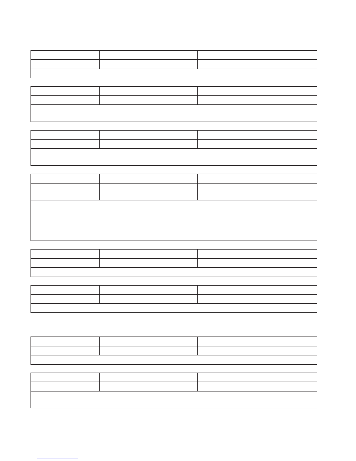
Nopsa command group 4 - logger commands
Real time buffer commands
Command Response
4/0 (Buffer info) 0x04 | 0x00 status | size*2 | write position*2
size: Ring buffer size (90), write position: position next to be written
Command Response
4/1 (Find oldest) 0x04 | 0x01 status | read position*2 | lap counter
Read position: position where is oldest data,
lap counter: how many times ring buffer has rolled over (0..255)
Command Response
4/2 (Find newest) 0x04 | 0x02 status | read position*2 | lap counter
Read position: position where is newest data,
lap counter: how many times ring buffer has rolled over (0..255)
Command Response
4/3 (Read buffer with
index)
0x04 | 0x03 | index*2 status | index*2 | lap counter |
timestamp*4 | id*2 | type | data*n
index: buffer read position
lap counter: how many times ring buffer has rolled over (0..255)
timestamp: 4-byte timestamp, see p. 26
id: data origin
type: 32 (STRUCT), see p. 21
Command Response
4/4 (Read next) 0x04 | 0x04 As in command 4/3
In case of no new data returns only status byte
Command Response
4/5 (Reread last) 0x04 | 0x05 As in command 4/3
Returns data which was read last. This has its uses when serial communication error happens.
Flash commands
Command Response
4/16 (Read fl ash) 0x04 | 0x10 | address*4 | count status | data*count
address: fl ash address, count: data byte count, data: see page 26
Command Response
4/17 (Find time) 0x04 | 0x11 | timestamp*4 status | address*4 | timestamp*4
timestamp: 4-byte timestamp, see p. 26, address: memory address where is data which is just
next (newer) from given timestamp, response timestamp: timestamp of the found data
Page 35
35
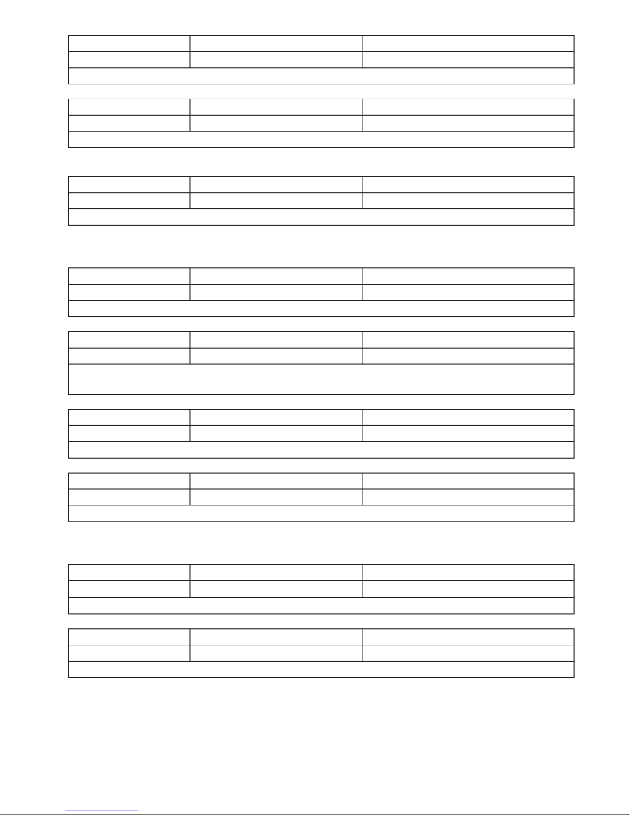
Command Response
4/18 (Give write pos.) 0x04 | 0x12 status | address*4
address: address where fl ash write is progressing
Command Response
4/19 (Flash size) 0x04 | 0x13 status | size*4
size: size of the fl ash memory
Command Response
4/20 (Flash erase) 0x04 | 0x14 status
Note! Jumper for clearing settings must be set (see page 9), so that command takes effect
Channel commands
Command Response
4/32 (Channel count) 0x04 | 0x20 status | count
Count: Informs how many channels device has (90)
Command Response
4/33 (Changed chan.) 0x04 | 0x21 status | fl ags*12
fl ags: Inform which channels have changed since last read operation, each channel is
represented by one bit, 1 = channel has changed since last read operation
Command Response
4/34 (Read channel) 0x04 | 0x22 | channel status | data*n
Channel: number 0..89, data: see page 18
Command Response
4/35 (Read next) 0x04 | 0x23 As in command 4/34
Note! If there is no new data only status byte will be received
Clock commands
Command Response
4/48 (Clock set) 0x04 | 0x30 | timestamp*4 status
timestamp: 4-byte time, see page 26
Command Response
4/49 (Clock fetch) 0x04 | 0x31 status | timestamp*4
timestamp: 4-byte time, see page 26
Page 36
RTR970PRO 7470
(+) (-) D1 D0
1 2 3 4
(-) (+)
B A 11 12
Power supply
9VDC (80mA)
Power supply
24VDC (100mA)
Analog outputs
4-20mA
4-20mA
4-20mA
4-20mA
transmitters
RS-485
FTR970-PRO
36
APPLICATIONS
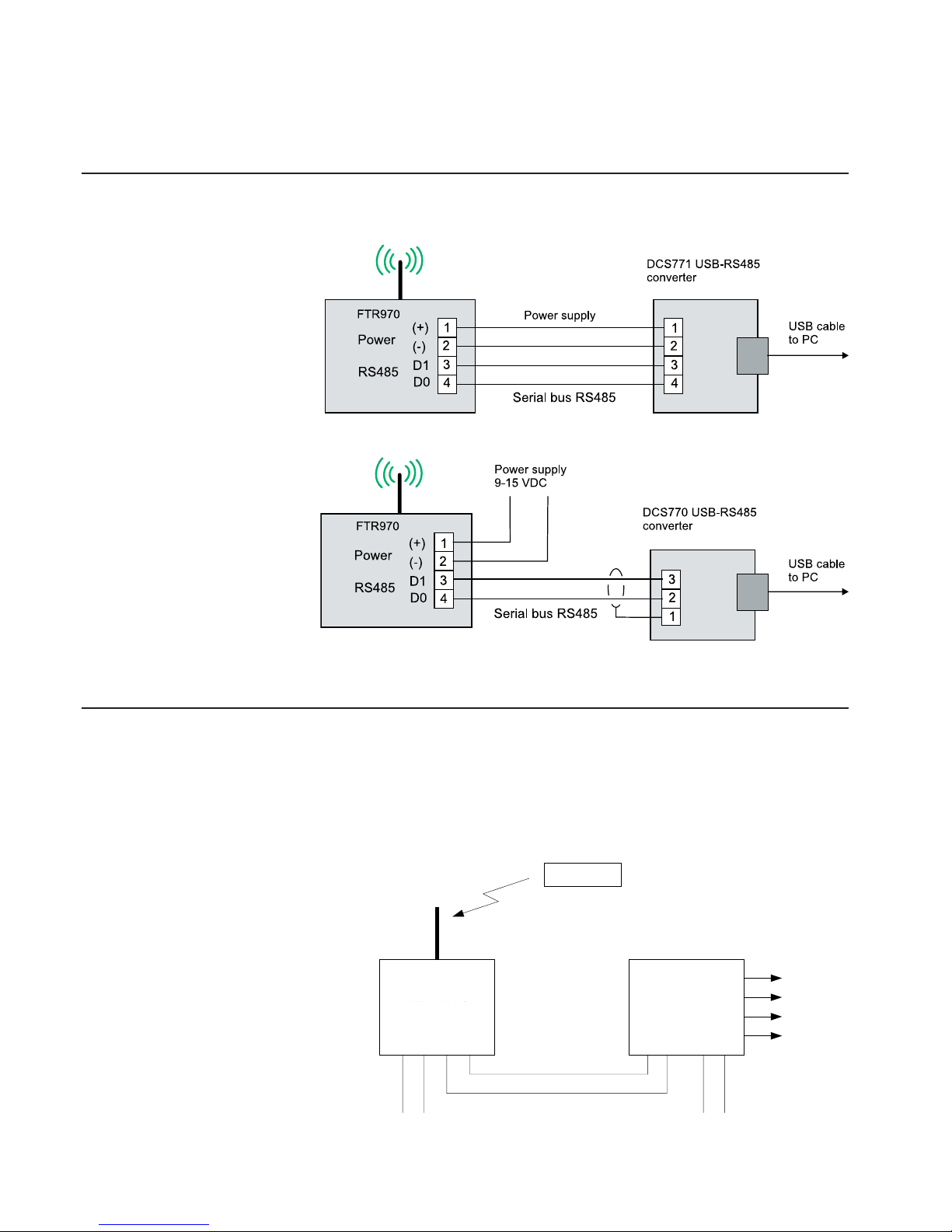
FTR970-PRO and 7470 output device
FTR970-PRO receiver can be used in conjunction with 7470 output unit. Devices are connected to
same RS-485 bus and confi gured using Mekuwin program or 6790 handheld programmer.
(Note: 2-wire-485 jumper is recommended to be on, see chapter Installing)
FTR970-PRO has 90 channels,
which can be confi gured to receive MTR/FTR series transmitters. 7470 will function as a bus
master that asks measuring values from the FTR970-PRO receiver and converts them to analog signals. Four channels can
be converted with one 7470.
Connecting FTR970-PRO to PC
Connecting the FTR970PRO
to the converter that has a
power supply to the receiver.
Connecting the FTR970-PRO
to the DCS770.
D1
D0
C
Page 37
37
TECHNICAL DATA
Radio receiver
Antenna
Connection: 50 ohm BNC-female connector
Standard antenna: Helix whip with BNC-connector
Receiver
Max input: +10 dBm
Frequency range: license free 433.92MHz
ERC/REC 70-03 subchannel f
(subchannel e in older specs)
Frequency range: 180 kHz
Selective fi lter: On, SAW-type
Sensitivity: -100 dBm (3·10-3 bit error rate)
Decoder
Channel memory: 90 channels
Buffer memory: 90 last receptions
Flash memory: 2Mb
Connections
RS-485
Connector: Detachable screw post connector,
3,81 mm raster, has also power input,
pole 1 +, pole 2 gnd,
pole 3 D1, pole 4 D0
Wire length maximum 1000 m.
Protocol: Nokeval SCL, Modbus RTU, Nopsa
Baud rate: 1200 / 2400 / 4800 / 9600 / 19200 /
38400 / 57600 / 115200 / 230400
RS-232
Connector: Detachable screw post connector,
3,81 mm raster, pole 5 gnd,
pole 6 RxD, pole 7 TxD
Wire length maximum 15 m.
Protocol: Nokeval SCL, Modbus RTU, Nopsa
Baud rate: 1200 / 2400 / 4800 / 9600 / 19200 /
38400 / 57600 / 115200 / 230400
USB
Connector: USB type B
Protocol: Nokeval SCL, Modbus RTU, Nopsa
Baud rate: 1200 / 2400 / 4800 / 9600 / 19200 /
38400 / 57600 / 115200 / 230400
Power connection
Connector 1 1,3 mm DC-jack, positive center pole
Connector 2 Detachable screw post connector,
3,81 mm raster, pole 1 +, pole 2 Connector 4 USB type B, female
Voltage: 8...28 VDC
Note! If the PDB version of the device
is 1.0, the supply voltage range is
9...15 VDC.
Consumption: 80 mA max
Real time clock
Accuracy: max ±3.5 ppm over whole temperature
range
(max error lower than 2 min per year)
Battery backup: Clock operates 48h without power
supply at a time
Environment
Op. temperature: -30...+60 °C
Protection class: IP65
Indicator leds
Side of the PCB
PWR: Power led
RS: Internal communication led
RF: Radio receive led
Top of the PCB
PRO: PRO module ready led
Radio: Serial communication led
Memory: Flash write led
Error: Error led
Settings
Connection: RS-485 or RS-232
Protocol: Nokeval SCL-Meku 1
Program: Mekuwin for Windows 98...XP
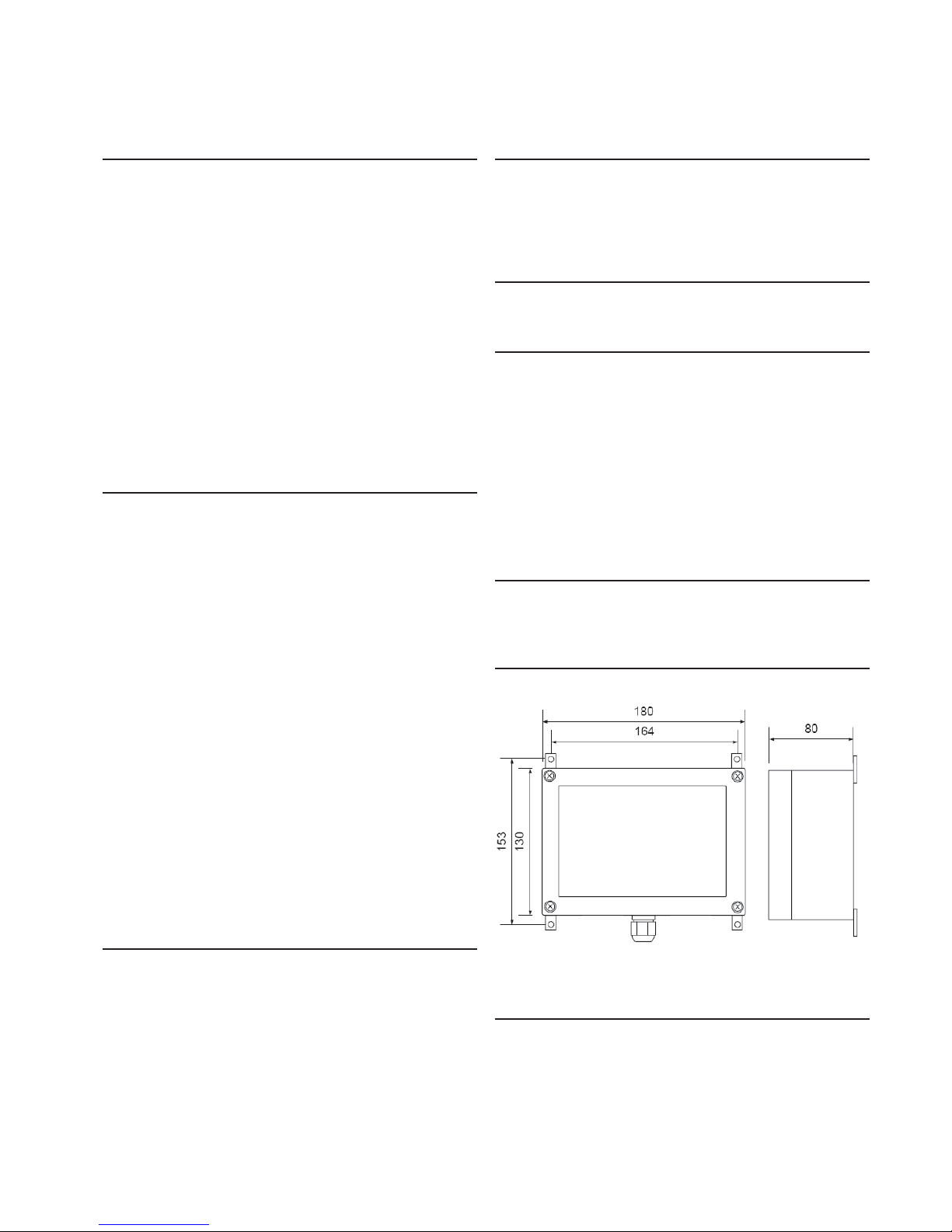
Dimensions
Case side dimension:
Antenna: 160 mm, Ø 14 mm
Regulations
EMC directive
EMC immunity EN 61326
EMC emissions EN 61326, class B
R&TTE directive
EN 300 220 class 3
EN 300 489
EN 300 339
Page 38

38
 Loading...