

Page 1
User manual
29.6.2007
V 1.1
FTR960
RADIO DATA REPEATER
Nokeval
Page 2

2
DESCRIPTION
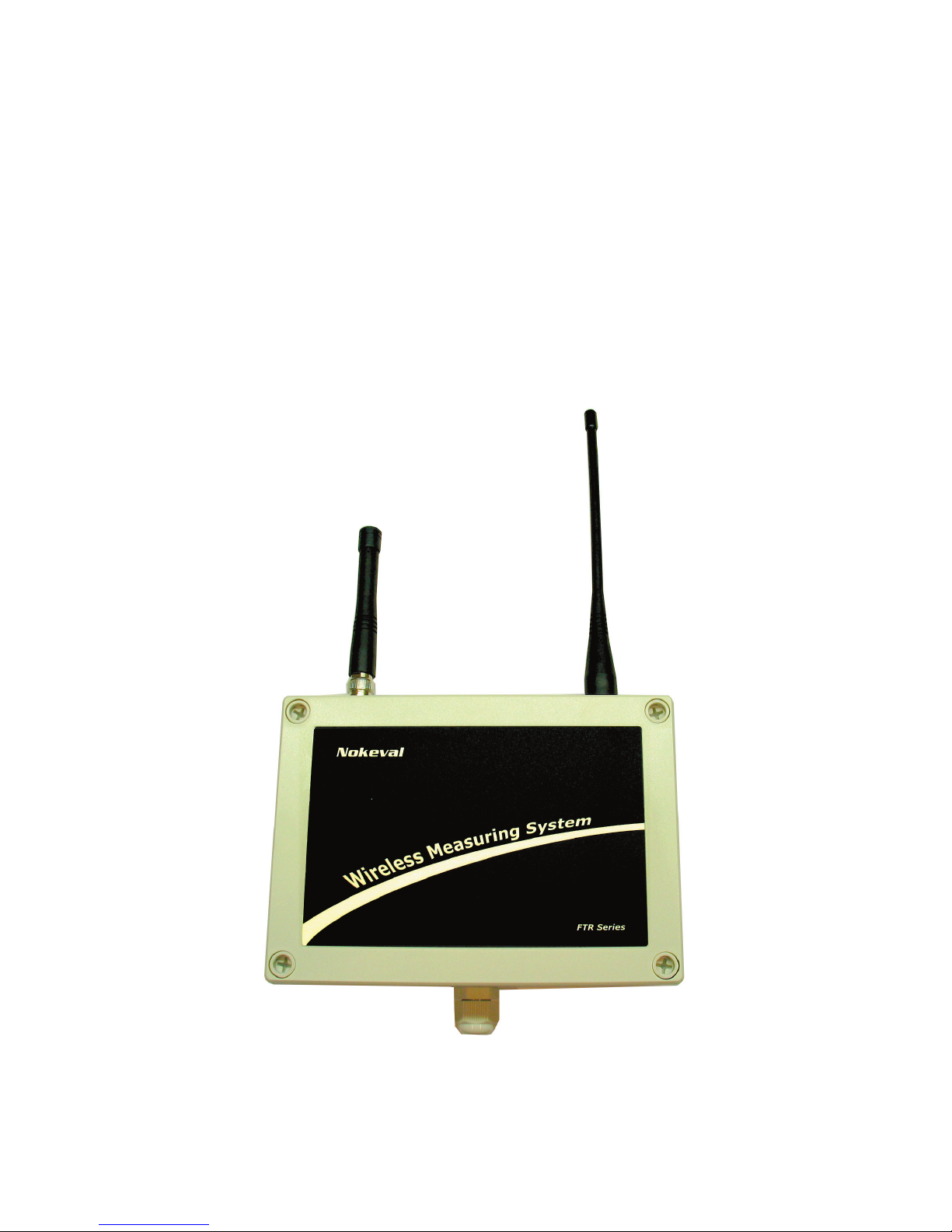
FTR960 is a radio data repeater for Nokeval MTR, FTR and KMR series wireless transmitters. It
relays the data packets that transmitters have sent so that large areas can be covered using only
one receiver. It automatically recognizes the types of the transmitters, so different kinds of transmitters can be used simultaneously. Transmitters can also have different transmission intervals.
FTR960 uses license free 433.92 MHz frequency band (ISM) so it can be freely used, for example, almost in whole Europe. FTR960 is housed in a field enclosure and equipped with detachable
screw post connectors. The repeater has three indicator LEDs and it requires 8..30 VDC.
Manufacturer
Nokeval Oy
Yrittäjäkatu 12
FI-37100 Nokia
Finland
Tel: +358 3 3424800
Fax: +358 3 3422066
Web: www.nokeval.com
Technical support: [email protected]
Page 3
3
INSTALLATION
Connections
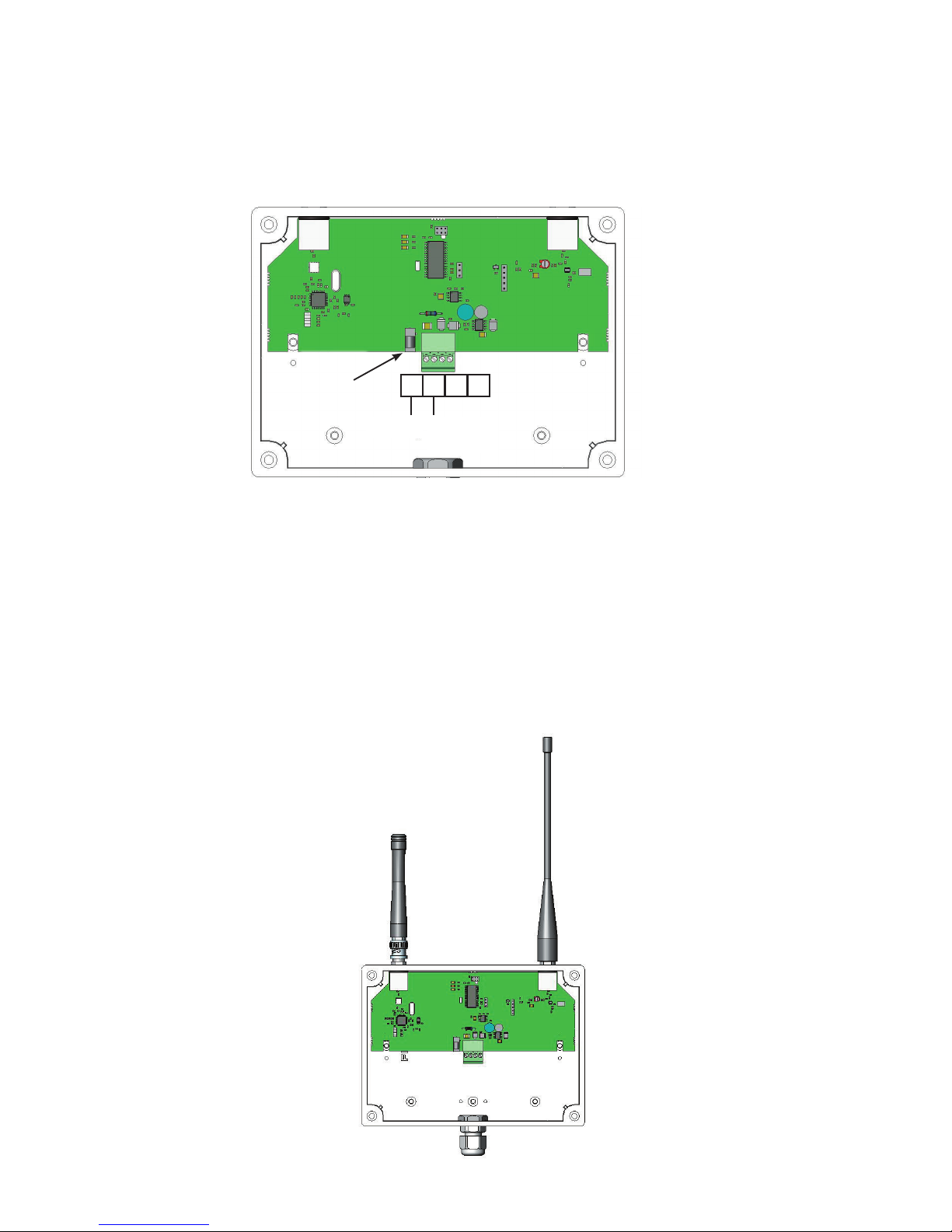
The supply voltage 8...30 VDC is connected using 1.3 mm DC jack (centre connector positive) or
by using detachable screw post connector terminals 1 (+) and 2 (-). Both supply voltage connectors are internally connected. The repeater is protected against wrong polarity of the supply voltage.
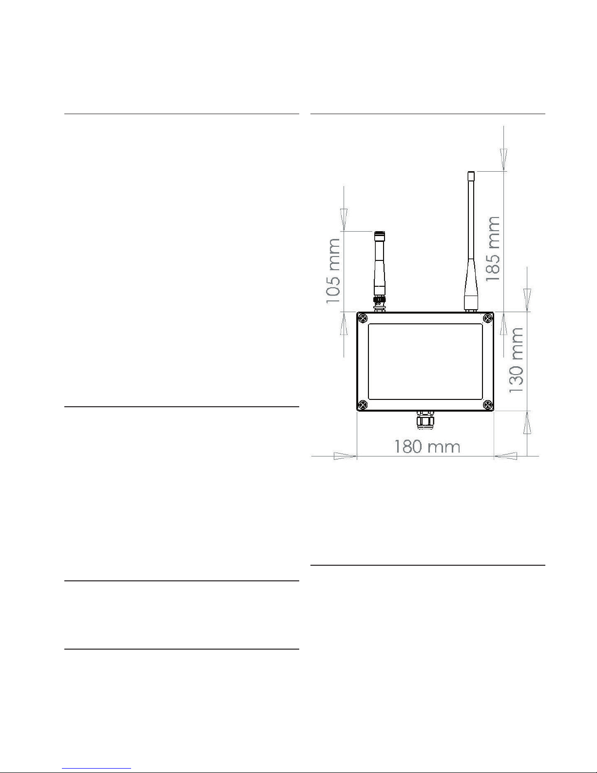
Connect the antennas to the BNC connectors at the top side of the case. First align the female
connector’s two guideposts to the male connector’s channels. Then press the BNC connector
in and lock the connector by rotating the male connector’s outer ring clockwise. If needed,
the antennas can be removed by rotating the rings counter clockwise and then pulling out the
antennas. Connect the antennas as shown in the picture below. The shorter antenna is connected
to the left-hand side BNC connector and the longer antenna to righ-hand side connector.
1,3 mm DC jack
1 2 3 4
GND8...30 VDC
Page 4
4
Power
TX
RX
Indicator lights
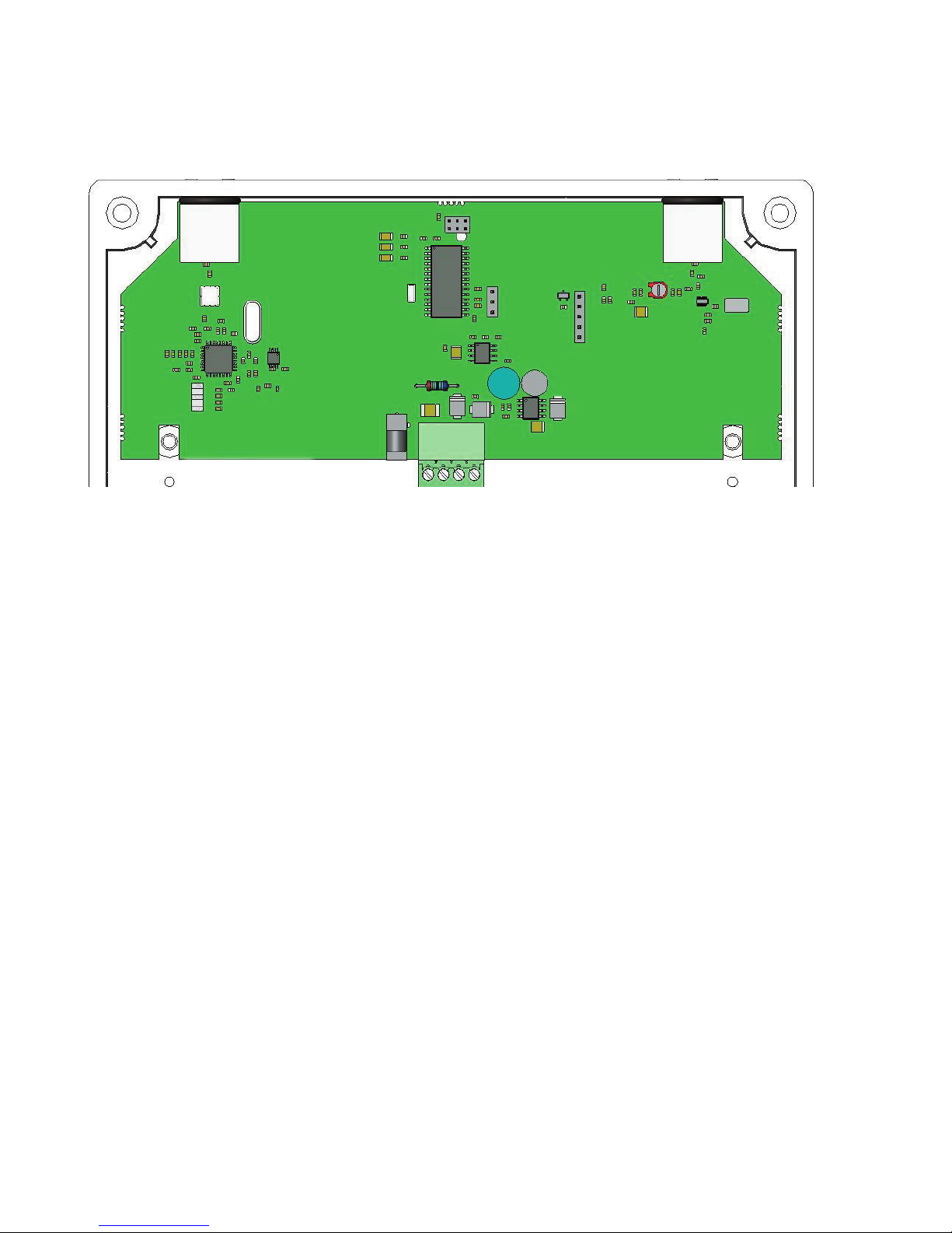
The device has three indicator lights: Power, TX and RX. In normal operation these lights are not
normally needed but they are very useful when troubleshooting error conditions.
Power
This indicator is always lit when power is applied to the device.
TX
This indicator light flashes every time data is sent.
RX
This indicator light flashes every time data is received
Page 5
5
Using two repeaters
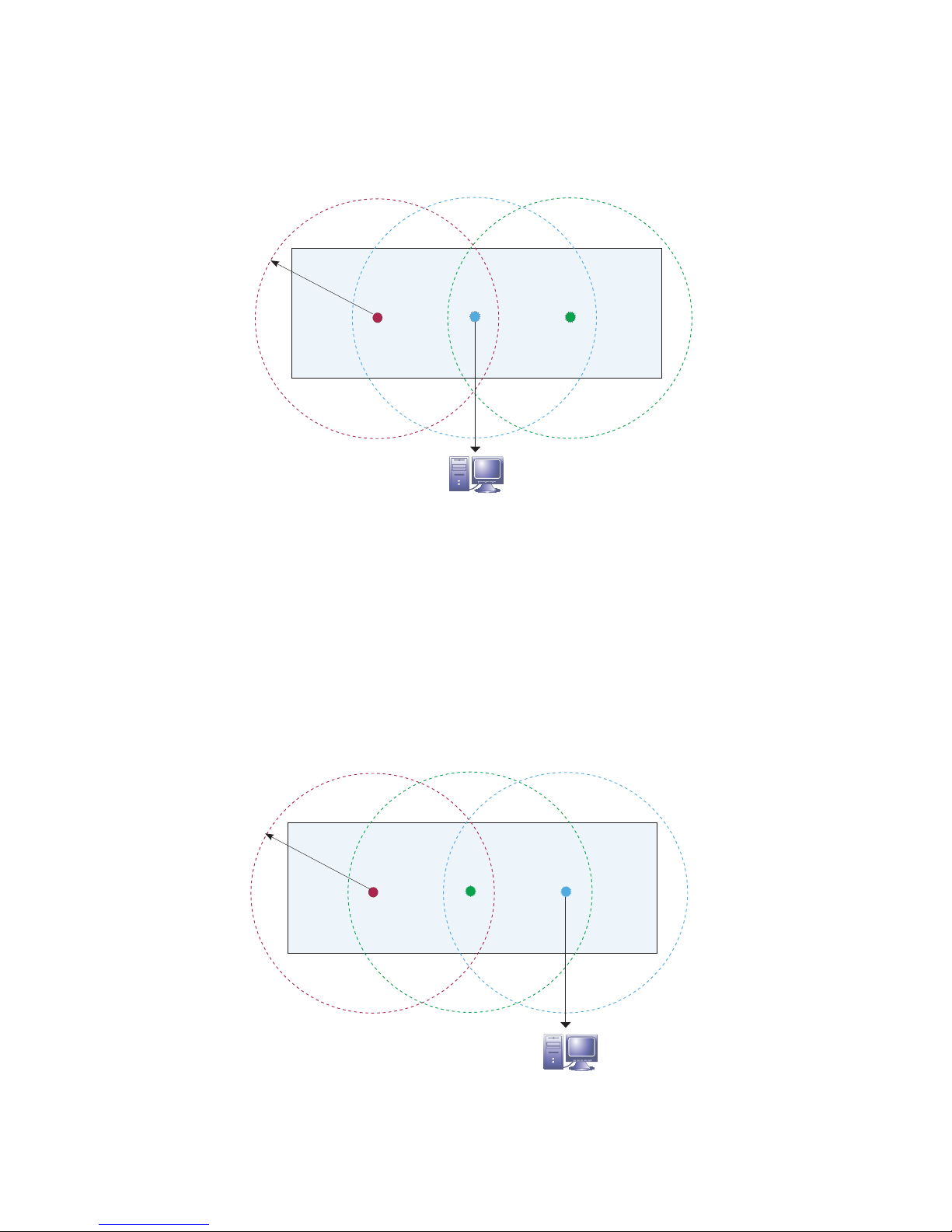
The picture below shows how two repeaters can be daisy chained.
The downside of daisy chaining is that now both repeaters relay also the data that they receive
from the other repeater. This increases radio traffic and therefore decreases the maximum number
of radio transmitters in a coverage area. See the transmitter’s manual or example table on page 6
how the use of repeaters affects the maximum number of transmitters.
Placing the repeaters
The repeater must be placed in the coverage area of at least one receiver. For example, in the
picture below the whole warehouse is covered using two repeaters that are placed near both
ends of the warehouse. In this way the receiver that is placed in the center of the warehouse can
receive transmissions anywhere from the warehouse.
The best installation site for the device is a fairly large grounded metal surface that has little
surrounding metal walls. The best signal levels are achieved when there is a line of sight to
transmitters. Walls and obstacles attenuate the signal and therefore decrease the coverage area.
On the other hand, metal surfaces can also cause reflections and increase the coverage area.
FTR960 FTR960
Warehouse
50..200 m
FTR970
Coverage area
RS-485 / RS-232 / USB
FTR960 FTR970
RS-485 / RS-232 / USB
Warehouse
50..200 m
FTR960
Coverage area
Page 6
6
The maximum number of transmitters
The maximum number of radio transmitters in a coverage area is limited by radio standards.
The use of repeaters reduces the maximum number of transmitters because repeaters use
the same frequency channel as transmitters. The following example table shows the allowed
maximum number of FTR262 transmitters in a coverage area. Corresponding table for all wireless
transmiiters is found from the user manual of the device.
For example, if you have transmission interval of 20 seconds and one repeater, the maximum
number of transmitters is 43*.
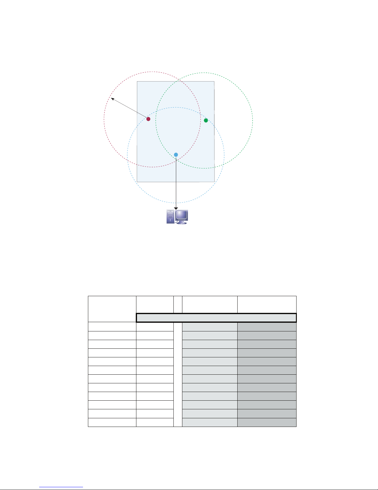
Both repeaters can be placed in the coverage area of one receiver like in the example picture
below.
Receiver
Receiver and Receiver and
1 repeater 2 repeaters
Maximum number of transmitters
5
22 11 7
10
43 22 14
20
87 43* 29
30
130 65 43
40
174 87 58
50
217 109 72
60
261 130 87
70
304 152 101
80
348 174 116
90
391 196 130
120
522 261 174
240
1043 522 348
Transmission
Interval (s)
FTR960
FTR960
RS-485 / RS-232 / USB
Warehouse
50..200 m
FTR970
Coverage
area
Page 7
7
SPECIFICATIONS
Radio
Receiver
Standard antenna: helical whip antenna
Connector: 50 Ω female BNC connector
Max input power: +10 dBm
Frequency band: license free 433.92MHz
subband e
according to ERC/REC 70-03
Bandwidth: 180 kHz
Selective filter: Yes, SAW type
Sensitivity: -100 dBm (3·10
-3
error ratio)
Transmitter
Standard antenna: Quarter-wave whip antenna
Connector: 50 Ω female BNC connector
Frequency band: license free 433.92MHz
subband e
according to ERC/REC 70-03
Transmit power: max +10 dBm
Supply voltage
Connector 1: 1.3 mm DC jack, centre
positive
Connector 2: detachable screw post
connector with 3.81 mm
raster
terminal 1 +, terminal 2 -
Voltage: 8...30 VDC
Current
consumption: 60 mA
Environment
Oper. temperature: -30...+60 °C
Protection class: IP65
LEDs
PWR: Power indicator
(behind RS and RF LEDS)
Tx: Radio transmission indicator
Rx: Radio reception indicator
Other
External dimensions
case: 180 x 130 x 60 mm (WHD)
RX antenna: 100 mm, Ø 14 mm
TX antenna: 178 mm, Ø 8...16 mm
Regulations
EMC directive
• EMC immunity EN 61326
• EMC emissions EN 61326, class B
R&TTE directive
• EN 300 220 class 3, Transmitter power class 8
• EN 301 489
• EN 300 339
Page 8

8
Nokeval
Yrittäjäkatu 12
37100 Nokia
Finland
Tel +358 3 3424800
Fax +358 3 3422066
www.nokeval.com
 Loading...