

Page 1
1
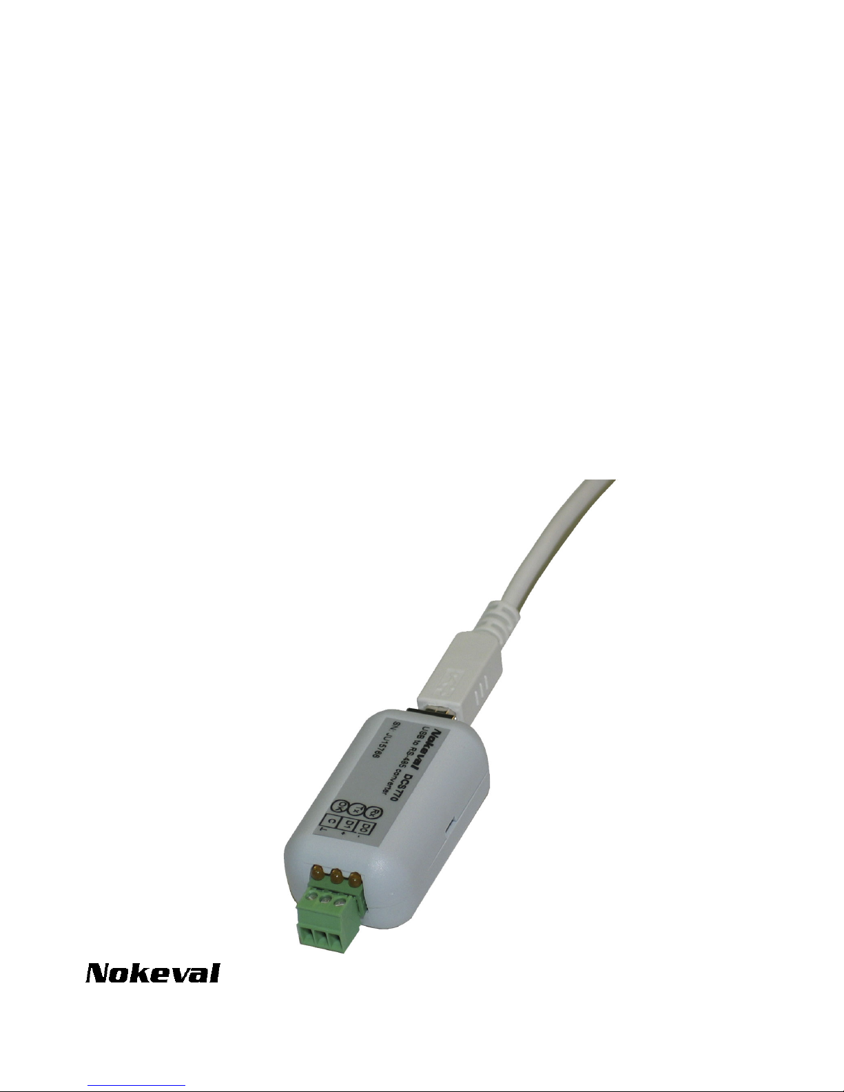
DCS770
USB-to-RS-485 converter
User manual
20.4.2005
V1.0
Page 2

INTRODUCTION
DCS770 is used to add an RS-485 connection in a PC computer. It is connected in a USB port, and the
drivers create a virtual COM port that can be used just as an ordinary COM port. Even the baud rates and bit
configuration can be changed in Windows port settings – these require no jumper settings. DCS770 can be
used with a variety of protocols, including Nokeval SCL and Modbus ASCII and RTU.
To aid troubleshooting, DCS770 is equipped with three indicator LEDs. It is small in size, and it has screw
terminals eliminating the need to make solder joints on cables.
Due to individual serial number on every device, these devices retain the COM port number if detached and
replugged, even in a different USB port. This increases reliability.
SPECIFICATIONS
USB connection
Connection: USB 1.1 or 2.0
Bus chip: FTDI FT232BM
Consumption: 100 mA
Connector: USB-B (USB-A-B lead
included).
RS-485 bus
Baud rates Any up to 115200 bit/s
Data bits 5..8
Parity All modes supported
Stop bits 1, 1.5, 2
Bus length 1000 m
Devices on bus max 32 normal load
devices or 128 1/4 load
devices
Load 1/4 load
General
Dimensions: 56x31x25 mm
Operating temp: 0...60 °C
Galvanic isolation: No
Regulations
EMC immunity
EN 61326
EMC emissions
EN 61326 class B
2
Page 3

THE DRIVERS
Drivers
The USB interface chip needs two drivers: one for USB bus and the other to create a virtual serial port.
The drivers can be obtained from a Nokeval Software CD or downloaded from the USB chip manufacturer:
www.ftdichip.com
(Drivers, FT232BM). The installation below assumes using CD, but using downloaded
drivers is quite similar.
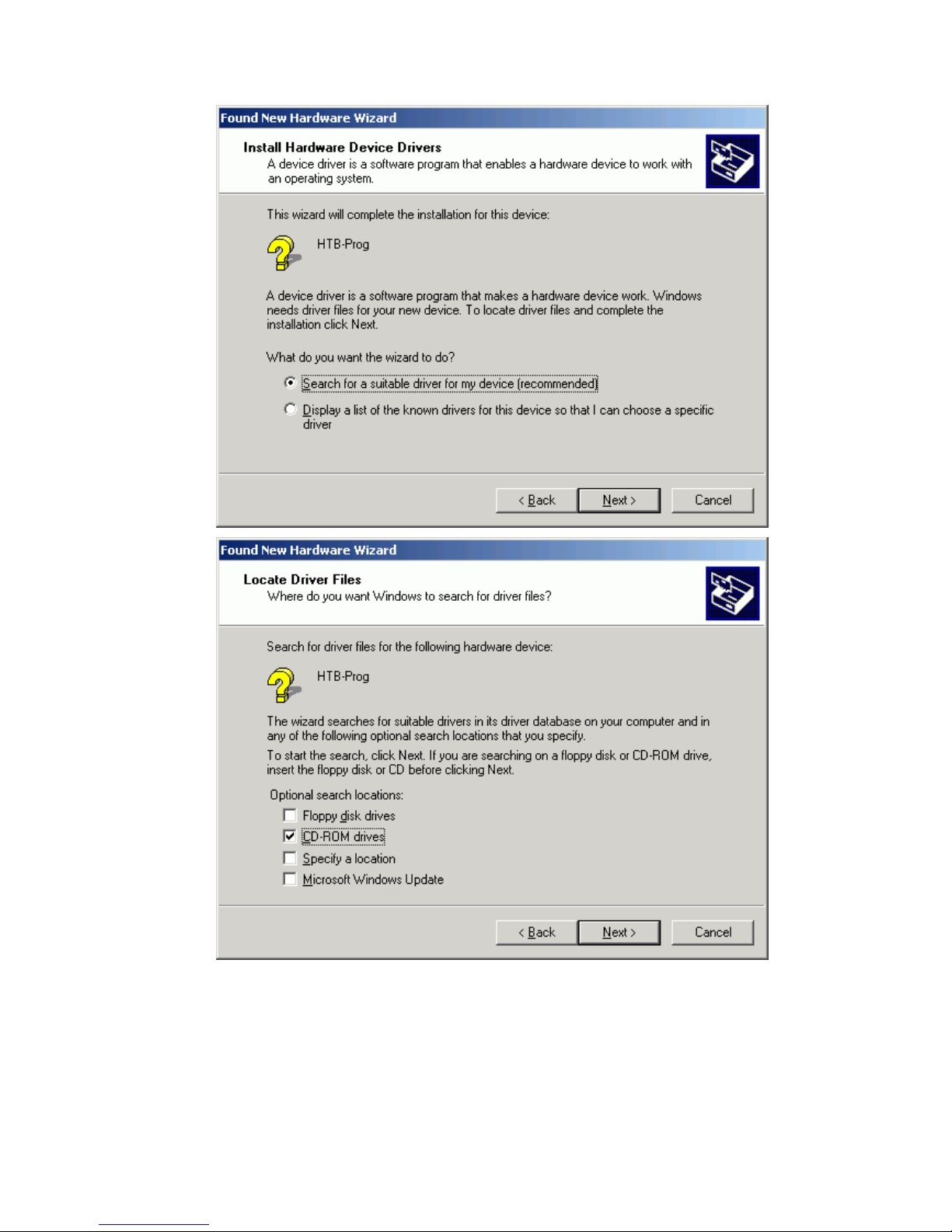
Insert the Nokeval Software CD and plug in the device. Windows should detect it and start installing
automatically:
3
Page 4
4
Page 5
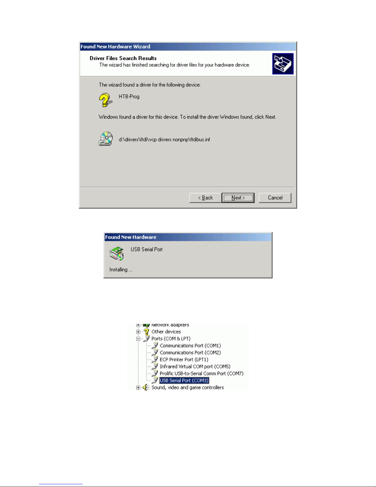
When USB bus driver ftdibus.inf is installed, Windows wants to install the virtual serial port driver, that makes
the device to look like an ordinary COM port.
Install in the same way as the bus driver. When all is complete, the OK indicator on the device should be lit.
Finally it is necessary to find out, which COM port represents the device. Open Control Panel, System,
Hardware, Device Manager. In the device tree, expand Ports, and there should be USB Serial Port (COM3),
for an example.
5
Page 6
CONNECTING
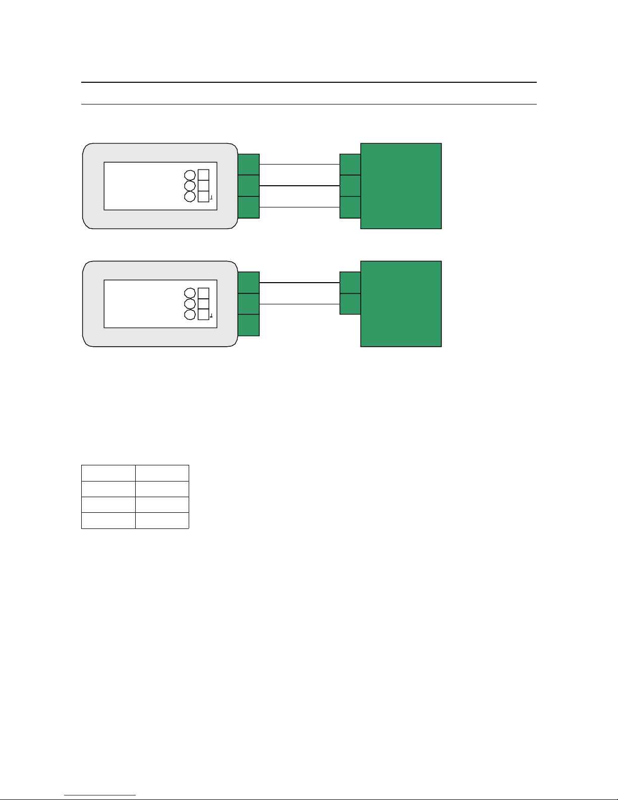
DCS770 has three terminals for RS-485 bus: D1, D0, and Common. These are connected 1:1 to the target
device(s). D1 and D0 carry the bits in both directions (one direction at a time, i.e. half-duplex), and Common
wire is used to equalize the ground potential of the bus devices.
Older Nokeval devices do not have Common terminal available – in that case connect only D1 and D0
(formerly called as A and B).
There has been quite rich use of names for the signal lines. Even EIA/TIA recommended ”A” and ”B” have
been used with two meanings. Nokeval has decided to use the names defined by Modbus standard, D1 and
D0. The table below shows typical names for the lines:
D1 D0
+-
BA
AB
The cable should be of a twisted pair, minimum diameter 0.5 mm (24 AWG). A shielded cable may be used
to increase immunity to disturbances. The shield should be grounded at one end only.
6
3
2
1
D0
D1
C
Rx
Tx
OK
-
+
Nokeva l
DCS770
USB t o RS- 485 c onverter
RS-485
device
C
D1
D0
Basic connection
NokevalA
B
Old Nokeval devices
3
2
1
D0
D1
C
Rx
Tx
OK
-
+
Nokeva l
DCS770
USB t o RS- 485 c onverter
Page 7
TERMINATING AND FAIL-SAFES
If the bus is longer than some dozens of meters or if high baud rates are used, the bus must be terminated in
order to avoid reflecting the signal from the bus ends. The reflections will cause bit errors.
The bus topology should be daisy-chain, although short stubs (a couple of meters) are acceptable. The first
and the last device on the bus should be terminated. Most RS-485 devices provide some means of
terminating without external components, typically closing a jumper or a DIP switch.
Fail-safe resistors are needed to ensure the correct state on the bus when nobody is transmitting. They
make at least 0.2 V voltage between lines D1 and D0. Modbus specification recommends that the bus has
only one device fail-safing. So it is natural to have the fail-safe on the master of the bus.
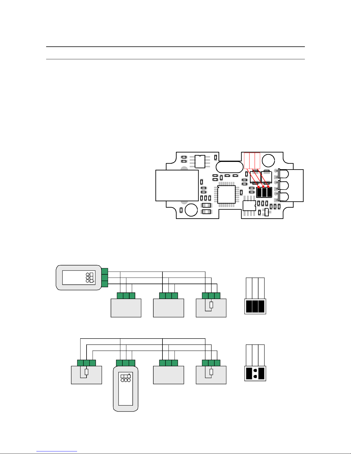
DCS770 can do both terminating and failsafing with jumper settings. Their default
setting is on. They may be changed by
opening the case – squeeze its sides
between your fingers and the case pops
open.
The termination provided by DCS770 is an
AC termination (there is a resistor 110 ohms
and a capacitor 1 nF in series). It is enabled
by closing the middle jumper inside the
case. It should be enabled, if DCS770 is the
first or the last device on the bus.
The fail-safe resistors are 500 ohms to 5 V, as recommended in Modbus specifications. They are enabled by
closing the first and the third jumper. They should be closed, if there is no other fail-safing devices on the
bus.
7
Failsafe
Failsafe
AC term
Termination: DCS770 at the end of the bus
3
2
1
D0
D1
C
Rx
Tx
OK
-
+
Nokeval
D0 D1 C D0 D1 C D0 D1 C
Termination: DCS770 in the middle of the bus
321
D0
D1
C
RxTxOK
-
+
Nokeval
D0 D1 C D0 D1 CD0 D1 C
Failsafe
AC te rm
Failsafe
Failsafe
AC te rm
Failsafe
Term
TermTerm
Page 8
TROUBLESHOOTING
The indicator LEDs in the DCS770 are very helpful when something is wrong with the communications.
Step 1: Drivers
Check if the OK LED is lit in the DCS770. If not, reinstall the drivers.
Step 2: Transmission
Start your PC application and check that the Tx LED is blinking on the DCS770. If not, there is something
wrong with your application – a wrong COM port probably.
Step 3: Reception
If the Tx LED is blinking but Rx is not, then your slave device is not responding. Check that it is powered up,
it is wired correctly, and that the serial settings are correct.
Step 4: Bus voltage
Use a multimeter to measure the voltage between D1 and D0 lines. It should be at least 0.2 V, D1 being
more positive. If it is 0 V, there is a short-circuit, or wire break, or no fail-safe enabled on any device.
Measure the voltage at every device, ensuring the polarity is still correct.
8
Yrittäjäkatu 12
37100 Nokia
Finland
Tel +358 3 3424800
Fax +358 3 3422066
www.nokeval.com
 Loading...