

Page 1
No 050101
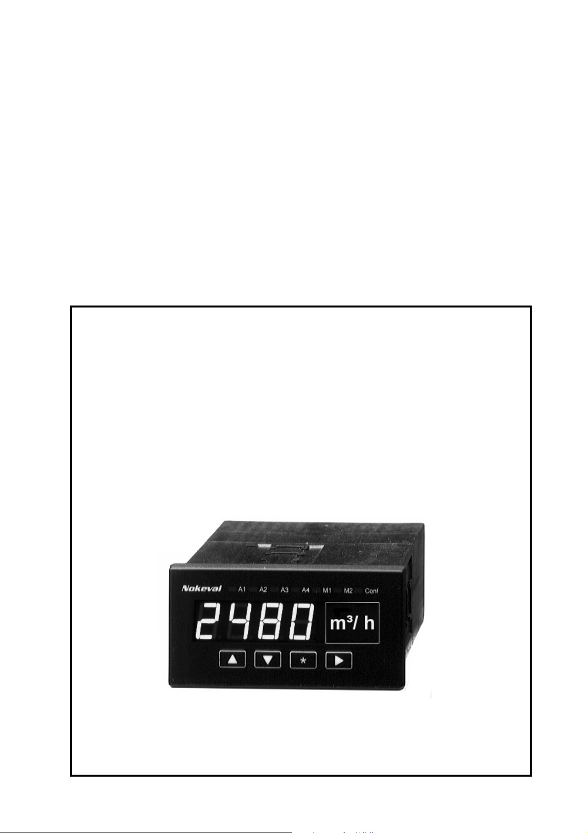
Nokeval
User's Manual
Models 201 & 202
1
Page 2

Contents
User's Manual Models 201 & 202 ..................................................................1
General description .............................................................................................................. 3
Autopowered LED-displays ............................................................................3
T ypical application ................................................................................................................ 3
Front panel buttons and indicators ..................................................................5
Configuration mode.................................................................................. 5
Resetting configuration parameters .......................................................... 5
Alarm level setting..................................................................................... 5
Alarm functions ........................................................................................ 5
Disable alarms.......................................................................................... 5
Manual reset............................................................................................. 5
Configuration...................................................................................................6
Enter into configuration mode .................................................................. 6
Access code for configuration ................................................................. 6
Description............................................................................................................................ 7
Input terminals.......................................................................................... 7
Alarm connections, only with model 202................................................... 7
Measuring mode ................................................................................................................... 7
Configuration mode..............................................................................................................7
Alarms off................................................................................................. 7
Nokeval Oy
Yrittäjäkatu 12
37100 NOKIA, FINLAND
Tel. +358 3-342 4800
Fax. +358 3-342 2066
email [email protected]
http:// www.nokeval.com
2
Page 3
Autopowered LED-displays
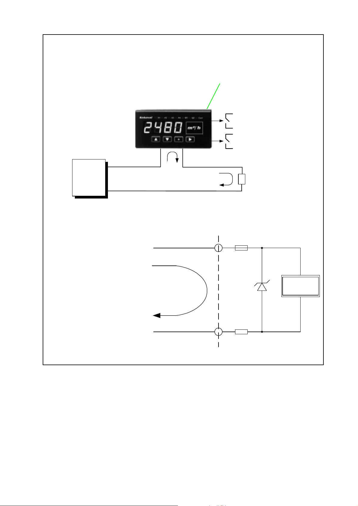
201 and 202
Space for unit of measure.
Commonly used unit collection is
delvered with the unit.
Transmitter
4-20 mA
• For process input 4-20 mA
• Without external power supply
• Loop resistance 240 ohm only
• 4-digit processor based display
• Scaling on front panel
• 2 settable alarms
• Pass words for alarms and
configuration
• Front panel rating IP 65
Nokeval
20.1
4-20 mA
4..20 mA
Polarity
protected
m³/h
(+)
( - )
Alarm 1 (low level)
Alarm 2 (High level)
Semiconductor fuse
Uz=4,8 V
3240
General description
Autopowered bright red LED-display needs no external
power supply. Current signal 4-20 mA provides the
necessary energy. Therefore, it is possible to install the
meter in places having no auxiliary power available.
You can now replace the autopowered LCD-displays,
having very poor visibility, by bright red LED-displays.
There are two models: 201 without alarms and model
202 with two alarm contacts.
Display scaling and configuration by front panel buttons.
Unit has digital filter for stabilizing the 4-digit display.
10 ohm
This feature is usefull in cases where large numerical
value is needed.
In model 202 You may configure two optional alarms,
high and low. Alarm value setting is designed for
applications where it can stay as it is once adjusted.
More versatile alarm settings and alternative alarm
modes offer our powered models 2011 and 2021. Pass
word is settable for entering configuration and alarm
stages.
Front panel protection IP65.
3
Page 4
T echnical specifications:
Input 4..20 mA
Display scaling -999....+9999
Accuracy 0.05% of span
Input voltage drop 201 continuous 4,8 V = 4-20 mA (comparable 240 Ω, non resistive)
20 2 continuous 7,3 V = 4-20 mA (comparable 340 Ω, non resistive) with alarms
Alarm relays (option) 2 solid state relays (SSR), max. 250 VAC, 150 mA
Alarm reset automatic or manual (hold) via front panel key
Alarm mode High and low level
Hysteresis Selectable 0..100 %
Display 4-digit red LED, 14.5 mm, adjustable brightness
Front plate protection IP65 with gasket, without gasket IP54
Push buttons Switches under front panel surface
Ambient temperature 0...+60 °C
T erminals Detachable 2,5 mm²
Weight 150 g
Order codes:
Model 201-4/20 mA 4-digit 4-20 mA loop powered indicator
Model 202-4/20 mA With optional 2 alarms
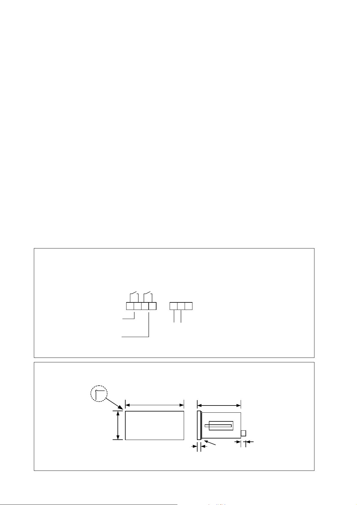
Connections:
Relays max. 250 VAC, 150 mA
Low level
alarm
High level
alarm
Case dimensions (mm):
ø2,5
48
A1 A2
654 321
7
96
-
+
Input
4-20 mA
Alarm only in model 202
Nc
T erminal 3 is not used
65
Cut out
43.7 x 90,7 mm ± 0.7 mm
4
6
Gasket (IP65)
10
Page 5
Front panel buttons and indicators
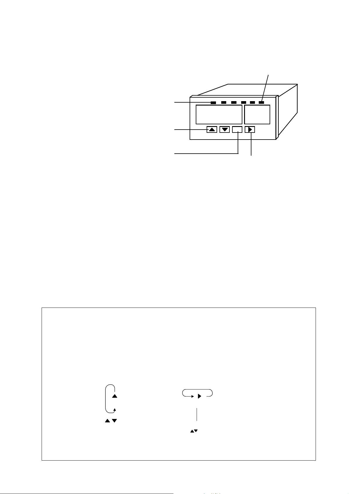
Alarm indicators LED's A1..A2.
5620
▲▼-arrow-buttons are used to change numerical
value and for moving on configuration menu.
*
Conf-led indicates
configuration mode
Exit from selected configuration stage
Configuration mode
Configuration can be started by pressing and holding
★- and ▲-keys simultaneously for 2 seconds.
Configuration stage is for selecting input, display
scaling and alarm function.
Specified instructions on pages 6-7 section
Configuration.
Resetting configuration parameters
Some times it is necessary to return indicator parameters
to factory defaults, e.g. if secret access code is
missed. Resetting can be done by pressing and
holding ★- and ➤-keys simultaneously for 2 seconds
when connecting input signal 4..20 mA. Prosedure will
reset all settings to factory defaults.
Alarm level setting
Enter selections in
configuration stage
Alarm functions
Alarms can be viewed in configuration mode. Special
instructions on pages 6-7, section configuration.
Disable alarms
Negative hysteresis value disables alarm function.
Manual reset
Auto reset is a standard function. Manual reset with
front panel ▼-key can be selected by choosing wider
hysteresis than full span (Hi -Lo). For example: Input
scaling is 0..100,0 i.e. full span is 100. Select hysteresis
larger than 100 (9999) and You will have manual reset.
Alarm levels are selected with ▲▼-buttons one number at a time.
Changing begins from the most signifigant digit on the left, desimal point
is selected first. Next digit to right is selected with ➤-button.
Accept and exit with ★ -button.
Value selection
400.00
Numbers
0...9
Selecting next digit
400.00
Desimal point selection
with -keys before
number selection
5
Page 6
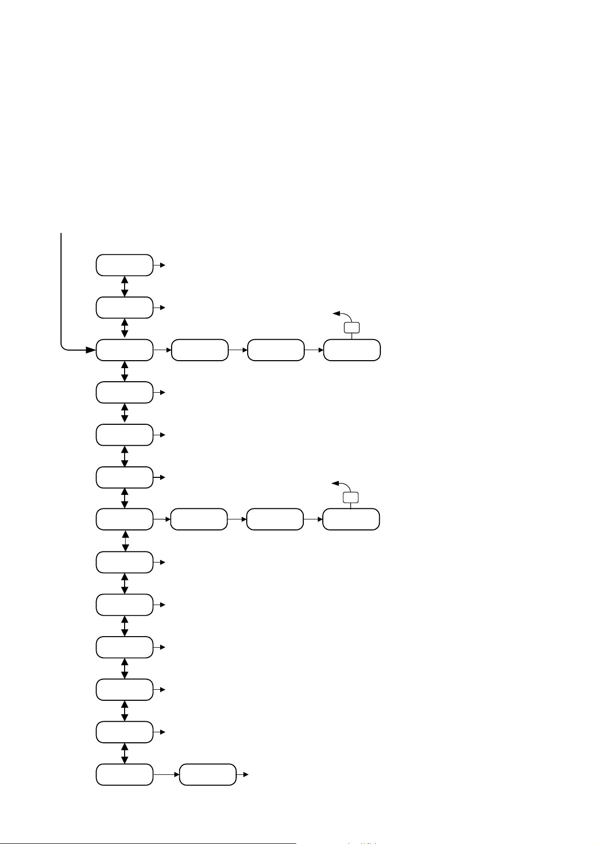
Configuration
Configuration can be started by pressing and holding
★- and ▲-keys simultaneously for 2 seconds. Arrow
keys ▲▼ moves up and down in main menu. Desired
function is selected with ➤-key. Save mode can be
selected directly by pushing ★-key in main menu.
Enter into configuration mode
Configuration can be started by pressing and holding
★- and ▲-keys simultaneously for 2 seconds. Arrow
keys ▲▼ moves up and down in main menu.
UnDo
SAVE
Undo changes
and exit
Save and
Exit
AL L
Old value
State of
change
Alarm values and hysteresis are selected in
configuration mode.
Changes can be restored by selecting text UnDO into
display and pressing ➤-key. Note! Detailed
configuration stage description on next page.
Access code for configuration
Configuration mode can be secured with pass word.
If function is selected unit asks CODE. Enter required
key combination as shown on page 8 section CFCo.
Return (★)
*
New value
Low level alarm setting.
AL H
ALHy
DEC
Lo
Hi
FiLt
Inte
High alarm setting, same routine as low level setting.
Hysteresis 0..50%. Negative value disables alarm function. Manual
reset with front panel keys can be selected by choosing wider
hysteresis than full span (Hi -Lo).
Decimals 0-3
(▲▼)
Return (★)
*
Old value
Display scaling for 20 mA, maximum value.
e.g. 20 mA=1000, decimals are selected in
section DEC. Same routine as section Lo.
Digital filter, factory default 0,2.
Value 1 means no filter
Display intensity 1-15.
15 = brightest
State of
change
New value
LO and HI
Display scaling for 4 mA.
Point selects number of digits
(not decimals) (▲▼) and then
select minmum scale value
with arrow keys (➤) (▲▼).
Number of decimals is selcted
in section DEC. When exiting
with ★-key, display show
selected value with decimals.
TrF
CFCO
CAL
Square root function: LIN = linear display
Sqrt = square root display
Pass word for configuration mode
CODE
Input calibration. Detailed instructions on page 8.
6
Page 7

Description
Input terminals
1 (+) signal loop (4…20mA)
2 (-) signal loop
3 Not used, can be used as a spare terminal
Voltage drop in 4..20 mA input loop is max 4.8 V. This
corresponds 240 ohm loop resistance. When alarms
are used (optional) voltage drop is max 7.3 V. Input is
secured for reversed polarity and over current tolerance
is 100 mA.
Alarm connections, only with model 202
4, 5 Low level alarm, display is lower than alarm level
6, 7 High level alarm, display is higher than alarm level
An example of Manual reset / hold function:
High level alarm is 100 °C and low level -5 °C. When
input is over 100 °C, LED A2 lits (relay A2 energized)
and it don't go off even if the input goes below 100 °C.
It must be resetted manually with front panel key ▼.
Alarm will be resetted also if input goes below selected
low level (-5°C). That is because both relays cannot be
energized at the same time. If You do not want to use
this bossibility given by the other alarm, select it's
value larger that the scaled range (not in use).
Alarms off
Negative hysteresis value disables alarm function.
➤➤
Dec
➤
➤➤
Decimal selection 0..3, i.e. 0.9, 0.99 or 0.999
Solid state realays,SSR: max. 250 V ±DC/AC,
150 mA, 12 ohm. Isolation between input loop 4 kV.
Alarms can be taken into use by removing jumper
inside the case. Voltage drop will increase to 7,3 V.
Measuring mode
This is normal operating mode. Scaled input signal is
in display. LED indicators functions are:
A1 = Low level indicator
A2 = High level indicator
Conf = Unit in configuration or calibration mode
Measuring mode can be changed to Configuration
mode by pressing simutaneously ▲★-keys. If Access
code is used it must be entered when display shows
Code, enter selected button combination.
Configuration mode
Undo, Save
Exit from configuration mode. SAVE saves new
configuration and Undo exits without saving.
➤➤
➤
➤➤
➤➤
➤
➤➤
➤➤
➤
➤➤
➤➤
➤
➤➤
1.000 = no filter
0.200 = normal filter
Lo, Hi
Lo and Hi scales display to input signal 4..20 mA. Lo
value is selected for input 4 mA and correspondingly Hi
value is for 20 mA input.
e.g. 4..20 mA = display Lo -100.. Hi +200
Filt
Display Filter. This fucntion stabiles display value
when wide measuring range is used.
Filter value can be set between 1 (min) ..0.010 (max).
e.g. 0.2 =(1/5) one new measurement and 4 old
values or
0.1 = (1/10) one new + 9 old values (slower)
Alarms are controlled with the filtered value (filter
affects to alarms reaction time).
Inte
Display intesity (brightness). You can change the
intensity with ▲▼-buttons. Hold ▼-key to decrease
intensity and vice versa.
In measuring mode intensity decreases automatically
when input is under 6 mA.
➤➤
➤
➤➤
➤➤
➤
➤➤
AL L, AL H
Alarm levels (L=low, H=high). Both alarms cannot be
energized at the same time. Therefore low level cannot
have higher value than high alarm and vice versa.
If input signal is under 3 mA relays will be de-energized.
(Normal open 'NO' relays needs energy to be closed).
ALHy
Alarm hysteresis is number of digits below and above
selected alarm level (both sides have same value).
Normally alarm relays are enegized when display value
goes to alarm level and de-energized when it goes over
hysteresis value.
Alarms can also have manual reset when hysteresis
value is set larger than measuring range (full span).
Manual reset is done with ▼-key from front panel.
➤➤
TrF
➤
➤➤
Transfer function selection.
Lin = normal fnction
Sqrt = square root function
Square root function enables even negative input. This
is usefull in cases where e.g. flow goes backwards.
CFCo
Access code for configuration mode. Access code is
formed with ▲▼★➤-keys. Code is formed with six
pushes of front panel buttons. Not in use when code is
set to (★★★★★★) (factory default).
If configuration access code is forgotten, all the settings
can be returned to factory defaults (not calibration) by
holding down buttons ★ and ➤ while connecting input
signal 4..20 mA.
7
➤➤
➤
➤➤
Page 8

Calibration
When calibrating, accurate 4 and 20 mA signals are
needed. The device is factory supplied calibrated,
and it is scaled to display 0-100.0 unless ordered
differently.
CAL >
If the device displays incorrect readings (more than
0.05% of range), it should be recalibrated. Before
doing that, ensure that the input signal is correct
(using a separate mA meter) and that the scaling
(Lo, Hi) is appropriate.
Enter configuration menu, select CAL and press ➤
key. Enter calibration password 112213,
▲▲▼▼▲★. “4_20” is displayed.
Feed a precise 4.000 mA signal to the device and
press ▼ key. Wait until the display reappears. Then
feed 20.000 mA and press ▲ key. Calibration values
are stored immediately and cannot be undone.
Finally exit to the configuration menu with ★ key.
Nokeval Oy
Yrittäjäkatu 12
37100 NOKIA, FINLAND
Tel. +358 3-342 4800
Fax. +358 3-342 2066
email [email protected]
http:// www.nokeval.com
8
 Loading...