

E-Kit Dämmerungsschalter
Mit einem Dämmerungsschalter lassen sich vom Umgebungslicht abhängige Schalt-vorgänge auslösen. Ein Einstellregler dient zur Abstimmung der Empfindlichkeit der Schaltschwelle.
Relais
Poti
LDR
Prozessor
Kondensator
Bild 1 Die einzelnen Bauteile
1. Beim Auspacken darauf achten, dass der kleine blaue Kondensator nicht verloren geht.
Zuerst werden die beiden schwarzen Kabel zur Stromversorgung an die Kontakte BLACK / RED auf der linken Seite der Platine angelötet (siehe dazu auch Bild 3).
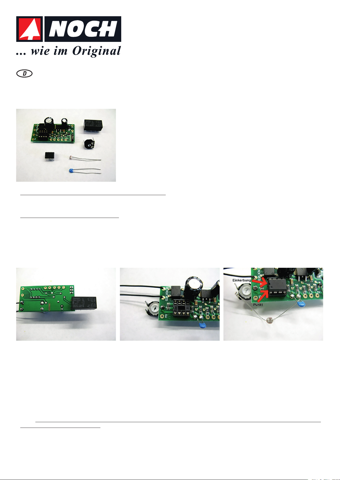
2. Als nächstes wird das Relais “Kopf über“, so wie auf dem Bild 2 zu sehen, angelötet.
Das Relais muss genauso wie abgebildet angelötet werden. NICHT ANDERS !!!
• Die Platine ist, so wie auf dem Bild gezeigt, hinzulegen.
• Die fünf goldenen Anschlüsse zeigen also nach oben.
• Das Relais ist so in die Kontakte einzusetzen, dass die Schrift, wie auf dem Bild 2 gezeigt, lesbar ist.
3. Jetzt erfolgt die Montage des Kondensators und des Potentiometers. Der Kondensator wird, wie auf dem Bild 3 gezeigt, zwischen die Kontakte -M- und L0 eingelötet. Das Potentiometer ist, wie auf dem Bild gezeigt, mit dem Mittelanschluss an den Kontakt + anzulöten (Bild 3).
Das Potentiometer (Poti) ist, so wie auf dem Bild 3 zu sehen, mit den Anschlüssen nach oben einzulöten. Der Anschluss ist mit + gekennzeichnet.
Wie wird der Dämmerungsschalter angeschlossen?
Die einzelnen Bestandteile der Schaltung:
• Microprozessor-Platine / Universal-Steuerung
• Microprozessor mit Software »Dämmerungsschalter« - Relais
• Potentiometer (auch als Poti bezeichnet) zur Einstellung der Empfindlichkeit
• Lichtempfindlicher Widerstand (LDR)
• Kondensator
Schrift auf dem
Relais lesbar !!!
Poti >>>>>
Kondensator >>>>>
Bild 2 Relais „Kopf über“ Bild 3 Poti & Kondensator Bild 4 Lichtempfindlicher Widerstand
4. Montage des lichtempfindlichen Widerstandes (LDR)
Die Anschlussdrähte des lichtempfindlichen Widerstandes sind vorsichtig auseinander zu biegen.
Tipp: Nicht direkt an der Bauteilunterseite biegen, sondern ein paar Millimeter da drunter (Bild 4).
• Der eine Anschluss des lichtempfindlichen Widerstandes wird an den Kontakt L0 angelötet.
• Der andere Anschluss wird an den unteren Draht des Potentiometers angelötet.
5. Einsetzen des Microprozessors
Der Microprozessor ist richtig herum in die Schaltung einzusetzen. Einfacher geht das, in dem man die Beinchen das Microprozessors ein klein wenig zusammen biegt, aber nur ein
klein wenig. Der schwarze Schaumstoff ist natürlich vor dem Einsetzen des Prozessors zu entfernen.
Auf der einen Seite hat der Microprozessor eine Einkerbung und einen Punkt. Das vorstehende Foto (Bild 4) zeigt das sehr deutlich. Den Microprozessor also mit der Einkerbung nach
links einsetzen. Alle acht Beinchen des Microprozessors sitzen jetzt gut in der Fassung.
Hinweis: Wird der Microprozessor falsch herum eingesetzt, führt das zur ZERSTÖRUNG des Microprozessors !!! Also: Genauso wie auf Bild 4 zu sehen den Microprozessor einsetzen.
Dabei auf den Punkt und die Einkerbung achten.
>>>>
unterer
Draht
Einsetzen Microprozessor
<<<<<
Kontakt
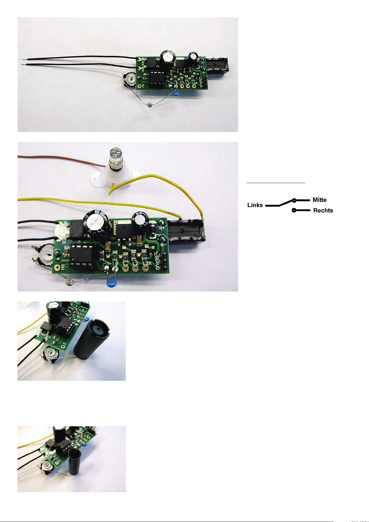
Die fertig zusammen gebaute Schaltung:
Anschluss Stromversorgung
Potentiometer (Poti)
Bild 5 Der Dämmerungsschalter
Lichtempfindlicher Widerstand (LDR)
Kondensator
Relais
6. Kontrolle der bisher ausgeführten Arbeiten
Auch wenn die Ungeduld sehr groß ist die Schaltung
jetzt mit Strom zu versorgen, sollte man immer die
Anschlüsse noch einmal kontrollieren.
Checkliste:
1. Relais richtig herum? “Kopf über“ (Bild 2)?
2. Kondensator an -M- und L0 (Bild 3)?
3. Poti richtig herum?
4. Lichtempfindlicher Widerstand richtig angeschlossen?
An Kontakt L0 (Bild 4)?
5. Microprozessor richtig eingesetzt (auch Bild 4)?
7. Erster Funktionstest des Dämmerungsschalters
Um die zusammengebaute Schaltung zu testen, muss
an das Relais ein Verbraucher angeschlossen werden.
Dazu eignet sich am Besten ein Beleuchtungssockel mit
Glühbirne oder LED. Das nachstehende Foto zeigt den
möglichen Anschluss (Bild 6). LED und Fassung nicht im
Lieferumfang enthalten.
Braune Leitung
Gelbe Leitung
Bild 6 Anschluss Relais
• Das Relais hat 6 Anschlüsse
mit insgesamt 2 Wechselschaltern
• Die obere Reihe ist Schalter 1
Gelbe Leitung
8. Die allerletzten Vorbereitungen für den Funktionstest
Der Einstellregler auf der linken Seite ist ungefähr in Mittelstellung zu drehen. Jetzt kann zum ersten Mal die Schaltung
mit Strom versorgt werden. Dazu werden die beiden schwarzen Kabel der Kontakte BLACK / RED ebenfalls an den
Eisenbahntrafo angeschlossen: Dauerstromausgang des Trafos (16 V Wechselstrom AC).
Die Polung braucht nicht beachtet zu werden. Um die Funktion des Dämmerungsschalters zu testen, muss jetzt entweder das Umgebungslicht abgedunkelt werden oder man bedient sich einer Kappe eines Filzstiftes. Wie auf dem Bild 7 zu
sehen kann man damit sehr schön “Dunkelheit erzeugen“. Durch anheben und absenken der Filzstiftkappe kann man
die Schaltschwelle des Dämmerungsschalter sehen.
Hier auf Bild 7 ist der lichtempfindliche Widerstand abgedunkelt und das Relais schaltet die Glühbirne / LED ein.
• Die untere Reihe ist Schalter 2
• Anschluss an linken und rechten Relais-Kontakt
• Mittlerer Relaiskontakt bleibt frei
• Schaltbild Relaiskontakt:
An den oberen linken Anschluss des Relais löten sie nun
ein circa 20 cm langes Kabel (zum Beispiel: gelb). An den
rechten oberen Anschluss des Relais löten Sie das gelbe
Kabel von dem Beleuchtungssockel an. Der mittlere obere
Anschluss bleibt frei. Das angelötete gelbe Kabel und das
braune vom Beleuchtungssockel schliessen sie nun am
Dauerstromausgang des Modellbahn-Transformators (16 V
Wechselstrom AC) an (Bild 6). Die Glühbirne / LED sollte
jetzt NICHT leuchten.
ACHTUNG:
Damit der Dämmerungsschalter richtig funktioniert, bedarf es einer gewissen Dunkelheit. Wenn man zum Beispiel den
lichtempfindlichen Widerstand nur mit der Hand abdeckt, dann reicht das bei Tageslicht NICHT. Auch bei Sonnenlicht
Bild 7 Abdunklung des LDR
funktioniert der Dämmerungsschalter nicht. Es ist eben ein Dämmerungsschalter und der will zum Auslösen Dämmerung
und Dunkelheit haben. Also: Gardinen zu und Licht aus !!!
Was kann man an das Relais anschließen und was hält das Relais aus?
Das Relais verfügt über zwei Schalter. Beide Schalter sind so genannte Wechselschalter. Die Hauptanwendung eines Dämmerungsschalters ist das Einschalten einer Beleuchtung bei
Dunkelheit. So können Beleuchtungen von Gebäuden, Straßenlaternen, Autos oder auch von einem Weihnachtsbaum auf der Modelllandschaft ein- und ausgeschaltet werden. Jeder der
beiden Wechselschalter kann 1 A schalten. Das bedeutet zum Beispiel, dass 2 x 50 = 100 LEDs mit jeweils 20 mA Stromverbrauch geschaltet werden können.
Wie kann der Dämmerungsschalter eingebaut werden?
Für eine gute Funktion des Dämmerungsschalters ist es erforderlich, dass der lichtempfindliche Widerstand die unterschiedlichen Helligkeitsdifferenzen des Umgebungslichtes auch gut erkennen kann.
<<<<<
Lichteinfall
Bild 8 Reduzierung Streulicht
Es muss „dunkel genug sein“, damit der Dämmerungsschalter das Relais schaltet. Man kann sich dazu eines sehr
guten Hilfsmittels bedienen. Aus einem schwarzen Stück Papier / Pappe stellt man sich eine nicht lichtdurchlässige Hülse
mit einem Durchmesser von 6 - 8 mm her.
Dazu wird einfach ein Papierstreifen zusammengerollt und mit Klebeband gesichert. Diese Hülse wird einfach über den
lichtempfindlichen Widerstand gesteckt. Siehe dazu nebenstehendes Foto.
Durch die schwarze Papierhülse wird seitliches Streulicht abgedeckt und nur direkter Lichteinfall von dem lichtempfindlichen Widerstand ausgewertet.
Wie stelle ich die Empfindlichkeit des Dämmerungsschalters ein?
Die Empfindlichkeit des Dämmerungsschalters wird mit dem Potentiometer eingestellt. Am besten stellt man zuerst das Potentiometer in Mittelstellung.
a) Dreht man dann den Pfeil nach oben wird der Dämmerungsschalter unempfindlicher.
b) Dreht man den Pfeil nach unten wird der Dämmerungsschalter deutlich empfindlicher.
Empfindlicher bedeutet, es muss dunkler sein, damit der Dämmerungsschalter auslöst.
Nimmt man jetzt zum Beispiel eine Taschenlampe zur Hilfe, kann man die Schaltschwelle sehr schön einstellen. Jetzt lassen sich zwei unterschiedliche Schaltschwellen für das Einschalten und das Ausschalten gut erkennen in dem man zum Beispiel den Durchmesser des Lichtkegels einer Taschenlampe variiert.
Wie kann man die Empfindlichkeit des Dämmerungsschalters erhöhen?
Eine Steigerung der Empfindlichkeit des Dämmerungsschalters ist zunächst durch Drehen des Einstellreglers möglich. Ist sehr wenig Umgebungslicht vorhanden, kann die Empfindlichkeit noch weiter erhöht werden. In dem Microprozessor sind zwei verschiedene Programme gespeichert. Das eine Programm wurde bisher benutzt, jetzt soll das zweite Programm
aufgerufen werden. Dieses zweite Programm arbeitet genauso wie das erste nur mit anderen Schaltschwellen, das heißt der Dämmerungsschalter funktioniert auch bei sehr, sehr
schwachem Umgebungslicht und ist super empfindlich. Es braucht nur ganz wenig Licht, um den Dämmerungsschalter auszulösen.
Wie kann man das zweite Programm des Microprozessors aufrufen?
Zuerst schaltet man den Strom komplett aus. Dann legt man eine Drahtbrücke zwischen den Anschlüssen + und SW.
Siehe dazu nebenstehendes Bild 9.
Durch die Drahtbrücke wird ein positives Signal auf den Eingang SW des Microprozessors gelegt. Daher weiß der Microprozessor jetzt, dass er das zweite Programm aufrufen soll.
Jetzt ist der Regler wieder in Mittelstellung zu drehen. Und wieder gilt: Wird der Regler nach oben gedreht wird die
Schaltung unempfindlicher und wird der Regler nach unten gedreht wird die Schaltung sehr, sehr empfindlich. Sehr, sehr
empfindlich bedeutet genau das. Es reicht schon das kleinste Licht um den Dämmerungsschalter zu aktivieren.
Jetzt ist der Dämmerungsschalter doch zu empfindlich.
Wie kann ich wieder das erste Programm aufrufen?
Bild 9 Drahtbrücke + und SW
Ist diese Einstellung zu empfindlich, dann kann man sehr leicht das erste Programm wieder aktivieren. Dazu schaltet man
wieder den Strom komplett aus. Jetzt trennt man die Drahtbrücke auf. Und schaltet den Strom wieder ein: Der Dämmerungsschalter arbeitet jetzt wieder mit dem ersten Programm und ist somit wesentlich unempfindlicher.
Was sollte man beim Gebrauch dieses Dämmerungsschalter vermeiden?
Zu vermeiden wäre eine so genannte Rückkopplung. So etwas erreicht man dadurch, dass man zum Beispiel die eingeschaltete Beleuchtung direkt auf den Dämmerungsschalter scheinen lässt. Dann geht die angeschlossene Beleuchtung dauernd an und aus und blinkt. Auf die Dauer ist so etwas nicht gut für das Relais.
Wie kann man die anderen E-Kits mit diesem Dämmerungsschalter zusammenschalten?
Zunächst bietet sich der E-Kit „Gebäude-Innenbeleuchtung“ (Bestellnummer 60270) an von einem Dämmerungsschalter geschaltet zu werden. Nach Einbruch der Dunkelheit beginnen ein oder mehrere Gebäude “zu leben“. Dazu wird einfach die “Gebäude-Innenbeleuchtung“ nicht direkt mit Strom versorgt, sondern die Stromversorgung wird über das Relais einund ausgeschaltet. Wie im Original auch kann natürlich zusätzlich mit dem anderen Relaiskontakt die Straßen- oder Bahnsteigbeleuchtung durch den Dämmerungsschalter weiterhin
geschaltet werden. Mit einem oder mehreren E-Kits „Servo mit Steuerung“ (Bestellnummer 60273) können bei Einbruch der Dämmerung bestimmte Attraktionen geschaltet werden.
Wieder ist hier ein Wechselschalter des Relais in die Versorgungsleitung (-en) des E-Kits “Servo mit Steuerung“ zu schalten. Zum Beispiel für nächtliche Gleisbauarbeiten oder für
nächtliches Be- und Entladen. Den zweiten Relaiskontakt kann man für die Baustellenbeleuchtung nutzen.
Wo kann man die eigene Installation des E-Kits anderen zeigen?
www.mymocom.com ist eine Plattform für alle Modellbahnbegeisterten. Dort können die eigenen Ideen wie der Dämmerungsschalter eingebaut ist und was der dann schaltet mit
anderen geteilt werden.
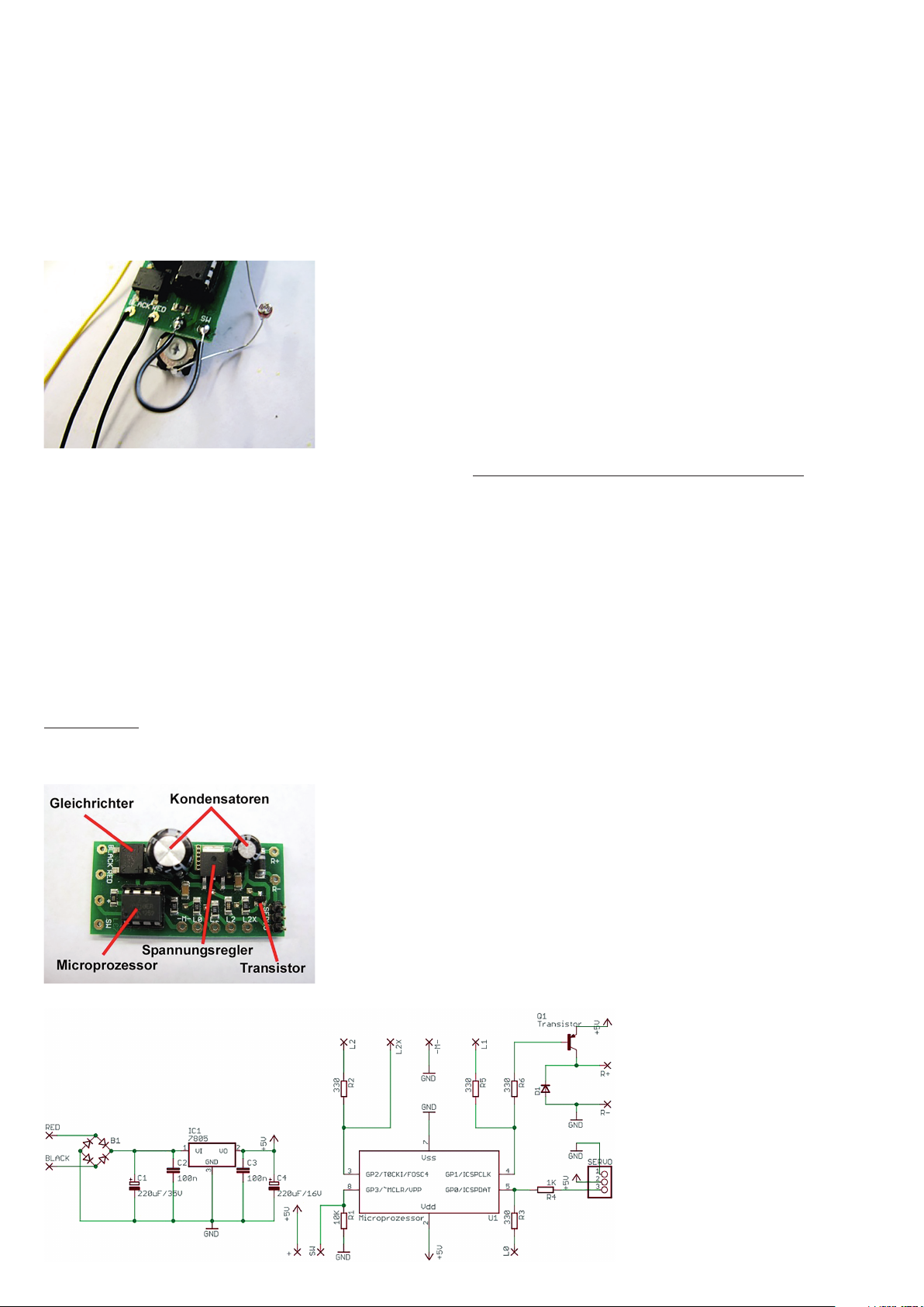
Wie funktioniert die Schaltung (Hardware) eigentlich?
Die Schaltung besteht aus:
• Microprozessor
• Spannungsversorgung
• Ein- und Ausgängen
Der Microprozessor arbeitet das gespeicherte Programm (Software) Zeile um Zeile ab und kann so die Eingänge abfragen
und die Ausgänge (Relais) schalten.
Das zentrale Bauteil ist der Microprozessor. Der Gleich richter, die Kondensatoren und der Spannungsregler sorgen für eine
zuverlässige Spannungsversorgung des Micro prozessors.
Die kleinen Bauteile mit der Beschriftung sind auf die Platine gelötete Widerstände für die einzelnen Ein- und Ausgänge
des Microprozessors. Damit auch ein Relais durch den Mikroprozessor geschaltet werden kann, ist ein Transistor auf der
Platine vorhanden.
Bild 10
Das ist der Schaltplan der Steuerungsplatine:
Bild 11

Was ist ein LDR?
LDR steht als Abkürzung für Light Dependent Resistor. In der Übersetzung bedeutet das lichtempfindlicher Widerstand. Ein solcher lichtempfindlicher Widerstand dient der Schaltung als
Sensor für das Umgebungslicht. Je stärker dieser Widerstand beleuchtet wird, desto geringer ist sein elektrischer Widerstand. Genau diese Widerstandsänderung wertet der Microprozessor aus und schaltet das Relais.
Was ist eine Hysterese?
Wird der LDR abgedunkelt, so schaltet bei einer bestimmten Schwelle das Relais die Glühbirne ein. Wird die Umgebungshelligkeit wieder erhöht so schaltet bei einer anderen Umgebungshelligkeit das Relais die Glühbirne aus. Diese Differenz nennt man Hysterese.
Umgesetzt wird das durch den Mikroprozessor der anhand des Widerstandswertes des LDR erkennt, ob er dann nun das Relais ein- oder ausschalten soll. Die jeweiligen Werte für das
Einschalten und das Ausschalten sind unterschiedlich. So kommt die Hysterese zustande. Natürlich kann man einen Dämmerungsschalter auch ohne diese Schaltschwelle bauen. Dann
aber flackert die Lampe bei Umgebungshelligkeiten, die nahe der Schaltschwelle liegen. Ohne diese Hysterese reagiert die Schaltung nahe der Schaltschwelle
schon auf geringste Änderungen des Lichtes.
Was sind die herausragenden Eigenschaften dieses Microprozessors?
Jeder Microprozessor muss irgendwie mit einem Takt versorgt werden um das Programm abzuarbeiten. Viele Computer nutzen dazu ein externes Schwingquarz. Dieser kleine Microcomputer hat jedoch schon einen internen Taktgenerator eingebaut. In nur einem Computerchip ist alles integriert was man zur Lösung von einfachen Steuerungsaufgaben braucht. Man
braucht nur 33 Befehle zu kennen und schon kann man den Microprozessor programmieren.
Wie arbeitet das gespeicherte Programm (Software) genau?
Zuerst fragt der Computer den Eingang SW ab. Hier wird geprüft, ob der erste oder der zweite Programmteil ausgeführt werden soll. Jetzt wird der Wert des lichtempfindlichen Widerstandes abgefragt. Ist dieser Wert größer als ein vorgegebener Vergleichswert, dann wird das Relais eingeschaltet. Ist aber dieser Wert kleiner als ein vorgegebener Vergleichswert, dann
wird das Relais nicht betätigt. Die beiden Werte für Ein- und Ausschalten sind unterschiedlich. So wurde die Hysterese programmiert. Sind diese Werte gleich hat man keine Hysterese.
Wo findet man weiterführende Informationen?
Eine sehr gute Anlaufstelle um mehr über den hier eingesetzten Microprozessor zu finden ist der Hersteller des Chips. Auf der Internetseite: www.microchip.com wird man schnell
fündig, wenn man nach dem hier eingesetzten Prozessor sucht. In das Suchfeld: Search Data Sheets gibt man PIC10F200 ein. Das Datenblatt des Microprozessors umfasst circa 100
Seiten. Hier ist ausführlich der kleine Microprozessor beschrieben.
E-Kit “Twilight Switch”
A twilight switch is designed to install animated lighting and automatic electronic switching. The sensitivity of the light sensor can be individually adjusted.
How to connect the twilight switch?
The single components of the switch:
• Microprocessor board / universal controler
• Microprocessor with “Twilight Switch” software – relay
• Potentiometer (also referred as poti) to adjust the sensitivity
• Light dependent resistor (LDR)
• Capacitor
1. During unpacking be careful, that the small blue capacitor will not get lost.
First, the both black cables for the electrical power supply will be soldered on the contacts BLACK / RED on the left side of the board (see also picture 3).
2. Next, the relay will be soldered “overhead” as you can see in picture 2.
The relay has to be soldered as illustrated. NOT IN A DIFFERENT WAY!
• You have to place the plate as shown in the picture.
• Thus, the five golden connections face upwards
• You have to insert the relay into the contacts, so that the letters are easy to read as shown in picture 2.
3. Now, continue with the installation of the capacitor and the potentiometer. The capacitor will be soldered between the contacts -M- and L0 (picture 3). The potentiometer with the
center terminal has to be soldered on the contact + (picture 3).
The potentiometer (poti) has to be soldered with the connections to the top, as you can see in picture 3. The connection is marked with +.
4. Installation of the light dependent resistor (LDR)
The connecting wires of the light dependent resistor have to be carefully bended apart.
Hint: Do not bend directly at the component base, but a few millimeters under there (picture 4).
• One connecting wire of the light dependent resistor will be soldered on the contact L0.
• The other one will be soldered on the upper wire of the potentiometer.
5. Inserting of the microprocessor
Make sure that the microprocessor is properly installed into the switch board. It is easier just to slightly bend the legs of the microprocessor together. Of course, the black foam
material has to be removed before inserting the processor.
On one side, the microprocessor has notch and a point. The following picture (picture 4) shows it very clearly. So set the microprocessor with the notch to the left. All eight legs of the
microprocessor sit well in the frame.
Note: If the microprocessor is set in the wrong way, it will cause the destruction of the microprocessor! Thus, install the microprocessor exactly as you can see in picture 4. Pay
attention to the point and the notch.

6. Supervising the work carried out so far: Even if you are eager to connect the switch to power now, you should always check the connections again.
Check list:
1. Relay in the right direction? “Overhead” (picture 2)?
2. Capacitor to -M- and L0 (picture 3)?
3. Poti in the right direction?
4. Light dependent resistor connected in the right way? To contact L0 (picture 4)?
5. Microprocessor connected properly (also picture 4)?
7. First performance check of the Twilight Switch
For testing the assembled switch, the relay has to be connected to an appliance. For this, a lighting base with a bulb or a LED will be convenient. The following picture shows the
possible connection (picture 6). LED and frame aren’t inclusive.
• The relay has 6 connections with a total of two changeover switches.
• The top series is switch 1.
• The lower series is switch 2.
• Connection to the left and the right relay contact.
• Middle relay contact stays free.
• The connection scheme of the relay contact:
At the upper left terminal of the relay you have to solder an approximately 20 cm long cable (e.g. yellow). At the right upper terminal of the relay you solder the yellow cable from the
lighting socket. The middle upper connection stays free. Now, you connect the soldered yellow cable and the brown one from the lighting socket with the continuous current output of
the model train transformer (16 v alternating current AC) (picture 6). The bulb / LED shouldn’t light now.
8. The very last preparations for the performance check
The adjustment knobs on the left should be turned approximately into the center position. Now, for the first time the switch can be powered. For this, both black cables of the contacts
BLACK / RED were connected to the railway transformer: continuous current output of the transformer (16 volts alternating current AC).
You haven’t take care to the polarity. For testing the function of the Twilight Switch, either the ambient light can be dimmed or you use a cap of a felt pen. As you can see in picture 7,
with this you can “generate darkness” very well. By raising and lowering the felt pen cap you can see the shifter shaft of the Twilight Switch.
Here on picture 7 the light dependent resistor is darkened and the relay turns on the bulb / LED.
ATTENTION:
For a properly working of the Twilight Switch, it requires certain darkness. For example, if you covers the light only by hand, it won’t be NOT enough in daylight. Also in sunlight, the
Twilight Switch doesn’t work. It’s just a Twilight Switch and wants to trigger dusk and darkness. So: Close the curtains and turn off the lights!
How to connect the relay and what does the relay withstand?
The relay has two switches. Both switches are so called changeover switches. The main application of the Twilight Switch is the turning on of lighting in darkness. So, the lighting of
buildings, street lamps, cars and also of a Christmas tree on the model landscape can be turned on and off. Each of the two changeover switches is able to switch 1 A. That means for
example, that 2x50=100 LEDs with each 20MA of power consumption can be switched.
How to install the Twilight Switch?
For a good function of the Twilight Switch, it’s necessary, that the light dependent resistor can see the differences in brightness of the ambient light clearly.
It has to be “dark enough”, that the twilight switch switches the relay.
For this, you can use a black piece of paper / cardboard creating a non-light-transmitting sleeve with a diameter of 6-8 mm.
For this, you easily roll up a strip of paper and fix it with tape. This sleeve is stuck into the light dependent resistor. See the picture 8 on the left side.
Because of the black paper tube lateral stray light is covered and only the direct light will be evaluated by the light dependent resistor.
How to adjust the sensitivity of the Twilight Switch?
The sensitivity of the Twilight Switch will be adjusted with the potentiometer. It’s the best, if you place the potentiometer in medial position first.
a) If you turn the arrow button to the top, the Twilight Switch will be less sensitive.
b) If you turn the arrow button to the bottom, the Twilight Switch will be significantly more sensitive.
More sensitive means, that it has to be darker, that the Twilight Switch is triggered. If you use for example a flashlight now, you can adjust the shifter shaft very well. Now, you can
recognize two different shifter shafts for the turning on and off clearly for example by variation of the diameter of the light cone of the flashlight.
How to increase the sensitivity of the Twilight Switch?
First, you can reach an increase of the sensitivity of the Twilight Switch by rotating the adjustment controler. If there’s not much ambience light, the sensibility can be raised up further.
In the microprocessor two different programs are saved. The one program is used so far, now the second program shall be used. The second program works exactly like the first but
with other switching levels, that means that the Twilight Switch works even during a very, very weak ambience light and it’s very sensible. Only a little light is necessary to trigger the
Twilight Switch.
How to call the second program of the microprocessor?
First, you completely turn off the power. Then you apply a jumper between the connections + and SW. See picture 9.
Because of the jumper a positive signal will be placed on the entry SW of the microprocessor. So, the microprocessor knows that he has to use the second program.
Now, the modulator has to be turned into medial position. Also here: If the modulator will be turned to the top, the switch will be less sensitive and if the regulator will be turned to the
bottom, the switch will be very, very sensitive. Very, very sensitive means exactly this. The smallest light is enough to activate the Twilight Switch.
Now, the Twilight Switch is too sensitive.
How to use the first program again?
If this setting is too sensitive, it’s very easy to active the first program again. For this, you have to turn off the power first. Now you disconnect the jumper. And turn on the power again:
Now the Twilight Switch is working with the first program again and thus it’s significantly less sensitive.
What should you avoid by using this Twilight Switch?
You have to avoid a so called self-excitation. You can reach something like that if you e.g. shine the turned on lightening directly to the Twilight Switch. Then, the connected lightening is
turned on and out the whole time and blinks. In the length of time, this is not good for the relay.

How to interconnect the other E-Kits with the twilight switch?
First, the E-kit “Interior Lighting for Buildings” (order number 60270) is suitable to be applied by a Twilight Switch. After nightfall one or more buildings come to life. For this, the
Interior Lighting for Buildings won’t be powered directly to power, but the power supply will be turned on and off by the relay. Like in the original, of course the road lighting and the
platform lighting can be switched by the other relay contact. With one or more E-Kits “Servo with controls” (order number 60273) certain attractions can be switched during nightfall.
Also here, a changeover switch of the relay has to be switched into the service pipe(s) of the E-Kit “Servo with Controls”. E.g. for nocturnal railway works or for nocturnal loading and
unloading. You can use the second relay contact for the construction site light.
Where I can show my own installation of the E-Kits?
www.mymocom.com is a platform for all model railway enthusiasts. There you can share your ideas about the installation and what it can switch with the others.
How does the switch (hardware) work exactly?
The switch board consists of:
• Microprocessor
• power supply
• entries and outlets
The microprocessor operates the stored program (software) line by line and so it can check the entries and regulate the outlets (relay).
The central element is the microprocessor. The detector, the capacitors and the voltage regulator arrange a reliable power supply of the microprocessor.
The small components with the signature are resistors, which are soldered on the plate for the single entries and outlets of the microprocessor. So that a relay can be switched by the
microprocessor, a transistor is included in the board.
What’s a LDR?
LDR stands for Light Dependent Resistor. Such a Light Dependent Resistor serves as a sensor for the ambient light. The stronger this resistance is illuminated, the lower electric
resistance. Exactly this resistance is change is evaluated by the microprocessor and switches the relay.
What’s a hysteresis?
If the LDR is shaded, the relay turns on the bulb after a certain barrier. If the ambient brightness will be turned up, the relay turns out the bulb in a different ambient brightness. This
difference is called hysteresis.
This is applied by the microprocessor, which can recognize, if it shall turn on or off the relay by the values of the resistance of the LDR. The respective values for the switching on and
off are different. In this way the hysteresis occurs. Of course you can create a Twilight Switch without this shifter shaft. But in this case, the lamp flutter at ambient brightness which is
near to the shifter shaft. Without the hysteresis the switch near to the shifter shaft reacts even to the slightest changes.
What are the special elements of this microprocessor?
Every microprocessor has to be supplied with a pulse for implementing the program. For this, a lot of computers use an extern oscillating crystal. But this small micro computer has
installed a small intern pulse generator. All things which are needed for a solution of a simple control task are implemented in only one computer chip. You only need to know 33
commands to code a microprocessor.
How does the saved program (software) work exactly?
First, the computer tests the entry SW. Here, it’s tested, whether the first or the second program will be used. Now the value of the light dependent resistor is polled. If this value is
greater than a predetermined reference value, the relay will be switched. But is the value is smaller than a predetermined reference value, the relay will not be switched. Both values for
switching on and off are different. Like this the hysteresis was programmed. If both values are identical, there’s no hysteresis.
Where I can find further information?
The manufacturer of the chip is a good resource to learn more about the microprocessor which is used here. On the website www.microchip.com you will find quickly something by
searching the used microprocessor. Enter “PIC10F200” in the search box “Search Data Sheets”. The data sheet of the microprocessor comprises approximately 100 pages. Here the
small microprocessor is described in detail.
Modellbauartikel, kein Spielzeug!
Model building item, not a toy! Not suitable for children under 14 years!
Article de modélisme. Ceci n’est pas un jouet.
Articolo di modellismo, non è un giocattolo!
Artículo para modelismo ¡No es un juguete!
Artigo para modelismo. Este artigo não é um brinquedo!
Výrobek ur`´cený pro modelá`´re, nejedná se o hra`´cku!
Modelbouwartikel, geen speelgoed!
Made in China.
NOCH GmbH & Co. KG
Lindauer Straße 49
D-88239 Wangen im Allgäu
Tel.: +49 - 75 22 - 97 80-0
Fax: +49 - 75 22 - 97 80-80
E-Mail: info@noch.de
www.noch.de und www.noch.com

60271 E-Kit Dämmerungsschalter
E-Kit “Twilight Switch”
Allgemeine Sicherheits- und Anwendungshinweise – Vor Gebrauch die Sicherheitshinweise und Anleitung genau lesen und beachten.
Dieser Artikel ist ein Modellbauartikel für anspruchsvolle Modellbauer und Sammler. Aufgrund maßstabs- und vorbildgetreuer bzw. funktionsbedingter Gestaltung
sind Spitzen, Kanten und filigrane Kleinteile enthalten. Für den Zusammenbau sind Werkzeuge wie ein scharfes Bastelmesser, eine scharfe Schere und spezieller Kleber nötig. Die fachgerechte Weiterverarbeitung dieses Modellbauproduktes birgt daher ein Verletzungsrisiko! Das Produkt gehört aus diesem Grund
nicht in die Hände von Kindern! Nach Fertigstellung ist dieser Artikel zum Einbau (Fixierung z.B. durch Klebstoff) in eine Modellbahnanlage, Schaustück usw. und
als hochwertiger Dekorationsartikel vorgesehen. Kein Spielzeug. Diesen Bausatz sowie Zubehör (Klebstoffe, Farben, Messer usw.) unbedingt außer Reich-
weite von Kindern unter 3 Jahren halten. Lassen Sie Kinder nur unter fachkundiger Aufsicht von erwachsenen Modellbauern diese Bausätze bearbeiten.
Nur die diesem Bausatz beiliegenden Teile und empfohlenes Zubehör verwenden. Hände und Werkzeug nach dem Basteln säubern. Bei der Verwendung von
Farben und Klebstoffen unbedingt beachten: Nicht essen, trinken oder rauchen. Farben und Klebstoffe nicht mit Augen, Haut oder Mund in Berührung bringen.
Dämpfe nicht einatmen. Von Zündquellen fernhalten. Die Anleitung und Hinweise des Herstellers genau beachten. Erste Hilfe bei Augenkontakt: Auge unter
fließendem Wasser ausspülen und dabei offen halten. Umgehend ärztliche Hilfe konsultieren. Diese Information gut aufbewahren.
General Safety and Application Instructions – Read and follow these safety precautions and instructions carefully before use.
This product is a model building item for the experienced modeller and collector. Due to its life-like and true to scale reproduction and functional form, this product
contains peaks, edges and delicate small parts. For assembly, tools like a sharp cutter, a sharp pair of scissors and special glue are necessary. Therefore, ap-
propriate working with this model building kit does present a risk of injury! For that reason this product is not for children! Upon completion, this product is
designed to be installed (e.g. fixed with glue) on to a model railway layout, diorama etc. and as a high-quality decorative item and not a toy. Keep this kit as well
as all accessories (glue, paints, cutter etc.) out of reach of children under 3 years of age! Let children build this kit only if supervised by a competent adult
modeller. Only use the parts of this kit included and recommended accessories. Please wash your hands and tools after modelling. For use of paints and glues
please follow these safety precautions: Do not eat, drink or smoke. Avoid any contact with eyes, skin or mouth. Do not breathe any vapours. Keep away from
ignition sources. Follow the instructions and safety precautions of the manufacturer carefully. First aid for contact with eyes: Flush the eye with clean water
holding the eyelid open. Immediately consult medical advice. Keep these instructions safe.
Consignes générales de sécurité et d’utilisation – Avant d‘utiliser ce produit, veuillez lire et suivre attentivement les consignes de sécurité et le
mode d‘emploi.
Ce produit est un modèle réduit pour modélistes et collectionneurs exigeants. En raison d‘une reproduction fidèle à l‘échelle de l‘original ainsi qu‘un respect de la
fonctionnalité, les kits contiennent objets pointus, des arêtes et des petites pièces filigranes. Pour le montage, des outils tels une lame aiguisée, des ciseaux aiguisés ainsi qu‘une colle spéciale sont nécessaires. De ce fait, un risque de blessure est possible! Pour cette raison, tenir ce produit hors de portée des enfants!
Après finition, ce produit est destiné à être intégré (p. ex. fixation avec de la colle) dans un réseau, un diorama etc. et peut être utiliser comme un produit décor de
haute qualité. Ce n‘est pas un jouet. Tenir absolument ce kit et les accessoires (colle, peintures, lames etc.) hors de portée des enfants de moins de 3 ans!
N‘utiliser que les pièces jointes et les accessoires recommandés. Nettoyer les mains et les outils après l‘usage. Pour l‘utilisation des colles et des peintures,
veuillez suivre les précautions suivantes: Ne pas manger, boire ou fumer lors de la manipulation. Eviter tout contact avec les yeux, la peau et la bouche. Ne pas
inhaler les vapeurs. Tenir à l‘écart des sources inflammables. Veuillez suivre attentivement le mode d‘emploi et les indications du fabricant. Premiers secours en
cas de contact avec les yeux: Rincer immédiatement et abondamment à l‘eau en les maintenant ouverts et consulter un ophtalmologiste. Veuillez bien conserver ces instructions.
Instrucciones Generales de Seguridad y Uso – Antes de montar leer las instrucciones de seguridad e indicaciones de montaje.
Este artículo es para modelistas y coleccionistas exigentes. Dado que las piezas son réplicas a medida y en algunos casos con funcionamiento, los modelos
pueden tener partes puntiagudas, cantos y piezas filigranas. Para su montaje se necesitan un cuchillo afilado, una tijera que corte y un pegamento especial. El
manipulado posterior de este producto puede llevar consigo un riesgo a lesionarse. ¡Debido a ello este artículo no puede estar al alcance de los niños! Una
vez acabado este artículo se puede montar en una maqueta (p.e. con pegamento), en el escaparate como decoración. No es un juguete. ¡En ningún momento
dejar el kit de montaje así como los accesorios (pegamento, colores, cuchillos, etc.) al alcance de niños menores de 3 años! La utilización de este producto por niños deberá realizarse solo bajo vigilancia de un adulto modelista. Solamente utilizar las piezas adjuntas y los accesorios indicados. Después del
trabajo de bricolaje limpiar las herramientas y las manos. Al utilizar los colores y pegamentos es indispensable: no comer, beber ni fumar. Los ojos, la piel y la
boca no deben entrar en contacto con los colores y pegamentos. No inhalar los vapores. No dejar cerca de fuentes de calor. Seguir exactamente las Instrucciones
e indicaciones del fabricante. Primer auxilio cuando hubo contacto con el ojo: lavar el ojo con agua corriente y mantenerlo abierto. Buscar inmediatamente
ayuda médica. Guardar bien esta información.
Algemene veiligheidsvoorschriften en gebruiksaanwijzingen – Voor gebruik de veiligheidswaarschuwingen en instructies goed lezen en opvolgen.
Dit product is een modelbouwartikel voor veeleisende modelbouwers en verzamelaars. Op basis van schaalverhoudingen, natuurgetrouwe- en functionele nabootsing zijn er scherpe punten en andere kleine, zeer fijne onderdelen aanwezig. Voor het in elkaar zetten is gereedschap zoals een scherp knutselmes, een scherpe
schaar en speciale lijm nodig. Hierdoor vormt ook vakkundige verwerking van dit modelbouwproduct kans op letsel! Daarom buiten bereik van kinderen
houden! Na voltooiing is dit artikel bedoeld voor plaatsing (vastzetten met bijvoorbeeld lijm) op een modelspoorweg, diorama etc. en als hoogwaardig decoratieartikel bedoeld. Geen speelgoed. Deze bouwdoos en toebehoren (lijm, verf, messen enz.) absoluut buiten bereik van kinderen onder de 3 jaar houden! Laat
kinderen alleen onder vakkundige begeleiding van een volwassen modelbouwer deze bouwset bewerken. Alleen de in deze bouwdoos ingesloten onderdelen en aanbevolen accessoires gebruiken. Handen en gereedschap na gebruik goed reinigen. Let op bij het gebruik van verf en lijm: niet eten, drinken of roken.
Verf en lijm niet in aanraking brengen met ogen, huid of mond. Niet inademen. Verwijderd houden van ontstekingsbronnen. De handleiding en instructies van de
fabrikant nauwkeurig opvolgen. Eerste hulp bij oogcontact: ogen open houden en met stromend water uitspoelen. Direct een arts raadplegen. Deze informatie
goed bewaren.
Sie können die aktuellste Version dieser Anleitung auf www.noch.de downloaden.
You can download the current version of this instruction manual at www.noch.de or www.noch.com.
 Loading...