

Page 1
南京拓微集成电路有限公司
NanJing Top Power ASIC Corp.
TP4056 1A Standalone Linear Li-lon Battery Charger with Thermal
Regulation in SOP-8
DESCRIPTION
The TP4056 is a complete constant-current/constant-voltage linear charger for single cell
lithium-ion batteries. Its SOP package and low external component count make the TP4056
ideally suited for portable applications. Furthermore, the TP4056 can work within USB and wall
adapter.
No blocking diode is required due to the internal PMOSFET architecture and have prevent to
negative Charge Current Circuit. Thermal feedback regulates the charge current to limit the die
temperature during high power operation or high ambient temperature. The charge voltage is
fixed at 4.2V, and the charge current can be programmed externally with a single resistor. The
TP4056 automatically terminates the charge cycle when the charge current drops to 1/10th the
programmed value after the final float voltage is reached.
TP4056 Other features include current monitor, under voltage lockout, automatic recharge and
two status pin to indicate charge termination and the presence of an input voltage.
FEATURES
· Programmable Charge Current Up to
1000mA
·No MOSFET, Sense Resistor or Blocking
Diode Required
· Complete Linear Charger in SOP-8
Package for Single Cell Lithium-Ion
Batteries
·Constant-Current/Constant-Voltage
·Charges Single Cell Li-Ion Batteries Directly
from USB Port
· Preset 4.2V Charge Voltage with 1.5%
Accuracy
·Automatic Recharge
·two Charge Status Output Pins
·C/10 Charge Termination
·2.9V Trickle Charge Threshold (TP4056)
·Soft-Start Limits Inrush Current
·Available Radiator in 8-Lead SOP Package,
the Radiator need connect GND or
impending
PACKAGE/ORDER INFORMATION
ABSOLUTE MAXIMUM RATINGS
·Input Supply Voltage(VCC):-0.3V~8V
·TEMP:-0.3V~10V
·CE:-0.3V~10V
·BAT Short-Circuit Duration:Continuous
·BAT Pin Current:1200mA
·PROG Pin Current:1200uA
·Maximum Junction Temperature:145℃
·Operating Ambient Temperature Range:-40
℃~85℃
·Lead Temp.(Soldering, 10sec):260℃
APPLICATIONS
·Cellular Telephones, PDAs, GPS
·Charging Docks and Cradles
·Digital Still Cameras, Portable Devices
·USB Bus-Powered Chargers,Chargers
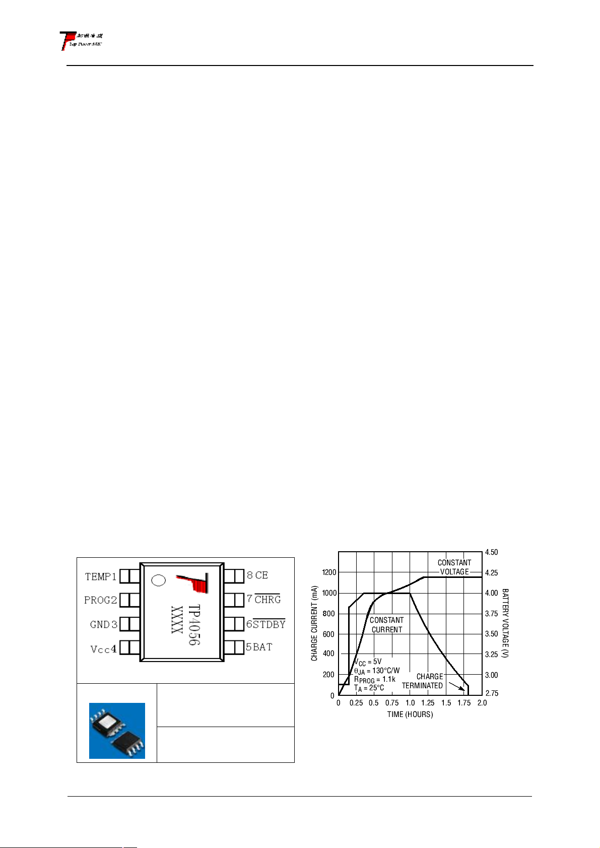
Complete Charge Cycle (1000mAh
Battery)
SOP-8
photo
ORDER PART NUMBER
TP4056-42-SOP8-PP
PART MARKING TP4056
1
Page 2
南京拓微集成电路有限公司
● ●
1200
NanJing Top Power ASIC Corp.
TEMP(Pin 1) :Temperature Sense Input Connecting TEMP pin to NTC thermistor’s output in
Lithium ion battery pack. If TEMP pin’s voltage is below 45% or above 80% of supply voltage VIN
for more than 0.15S, this means that battery’s temperature is too high or too low, charging is
suspended. The temperature sense function can be disabled by grounding the TEMP pin.
PROG(Pin 2): Constant Charge Current Setting and Charge Current Monitor Pin charge
current is set by connecting a resistor RISET from this pin to GND. When in precharge mode, the
ISET pin’s voltage is regulated to 0.2V. When in constant charge current mode, the ISET pin’s
voltage is regulated to 2V.In all modes during charging, the voltage on ISET pin can be used to
measure the charge current as follows:
GND(Pin3): Ground Terminal
V
BAT
PROG
PROG
IR=×
(V
PROG
=1V)
Vcc(Pin 4): Positive Input Supply Voltage VIN is the power supply to the internal circuit. When
VIN drops to within 30mv of the BAT pin voltage, TP4056 enters low power sleep mode, dropping
BAT pin’s current to less than 2uA.
BAT(Pin5): Battery Connection Pin. Connect the positive terminal of the battery to BAT pin. BAT
pin draws less than 2uA current in chip disable mode or in sleep mode. BAT pin provides charge
current to the battery and provides regulation voltage of 4.2V.
(Pin6): Open Drain Charge Status Output When the battery Charge Termination, the
pin is pulled low by an internal switch, otherwise pin is in high impedance state.
(Pin7): Open Drain Charge Status Output When the battery is being charged, the
pin is pulled low by an internal switch, otherwise pin is in high impedance state.
CE(Pin8): Chip Enable Input. A high input will put the device in the normal operating mode.
Pulling the CE pin to low level will put the YP4056 into disable mode. The CE pin can be driven by
TTL or CMOS logic level.
ELECTRICAL CHARACTERISTICS
The ● denotes specifications which apply over the full operating temperature range, otherwise
specifications are at TA=25℃,V
SYMBOL PARAMETER CONDITIONS MIN TYP MAX
V
CC
ICC
V
FLOAL
I
BAT
I
TRIKL
V
TRIKL
V
TRHYS
T
LIM
Input Supply Voltage ● 4.0 5 8.0 V
Input Supply Current Charge Mode, R
Regulated Output (Float)
Voltage
BAT Pin Current
Text condition:VBAT=4.0V
Trickle Charge Current V
Trickle Charge Threshold
Voltage
Trickle Charge Hysteresis
Voltage
Junction Temperature in
Constant Temperature
Mode
=5V,unless otherwise noted.
CC
PROG
StandbyMode(Charge
Terminated)
Shutdown Mode (R
Connected,
< VUV)
V
0℃≤TA≤85℃,I
R
= 2.4k, Current
PROG
CC
< V
PROG
BAT
BAT
Mode
R
Mode
Standby Mode, V
= 1.2k, Current
PROG
BAT
= 1.2k
Not
, or V
=40mA 4.137 4.2 4.263 V
= 4.2V
CC
●
150
55
55
●
●
●
450
950
0
500
1000
-2.5
, R
BAT<VTRIKL
R
=1.2K, V
PROG
R
=1.2K 60 80 100 mV
PROG
=1.2K ● 120 130 140 mA
PROG
Rising 2.8 2.9 3.0 V
BAT
145 ℃
500
100
100
550
1050
-6
UNI
TS
μA
μA
μA
mA
mA
μA
2
Page 3
南京拓微集成电路有限公司
NanJing Top Power ASIC Corp.
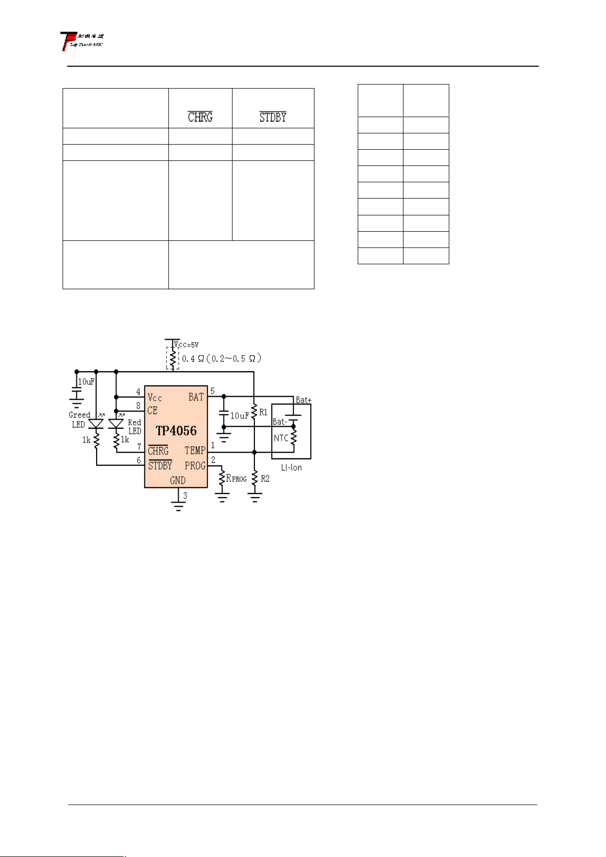
indicator light state
Charge state
charging bright extinguish
Charge Termination extinguish
Vin too low;
Temperature of
battery too low or
too high;
no battery
BAT PIN Connect
10u Capacitance;
No battery
Red LED
extinguish
Greed LED bright,Red
LED Coruscate T=1-4 S
TYPICAL APPLICATIONS
Greed LED
bright
extinguish
Rprog Current Setting
RPROG
(k)
10 130
5 250
4 300
3 400
2 580
1.66 690
1.5 780
1.33 900
1.2 1000
I
BAT
(mA)
3
 Loading...