

NOBO NOBOBOARD PPC COLOR Stand Assembly Manual
NOBOBOARD PPC COLOR
Stand Assembly Manual
Warning
• Please be sure to perform the installation and assembly based on this manual. Incorrect installation or assembly will be the cause of
injury.
• Please have 2 or more persons lift the Copyboard when installing or removing it.
•For details on installation, also refer to the copyboard’s “User’s Manual” and “Assembly and Setup Manual”.
STAND PACKAGING LIST
Please open the carton and check the parts.
In the rare event that something is missing, please contact your store of purchase.
T-shape legs (with casters): × 2, horizontal bars × 2, Frame caps × 2, Pipe caps × 4, lock-screws × 2,
hexagonal socket screws × 8, flat washers × 8, hexagonal wrench × 1, Stay × 1
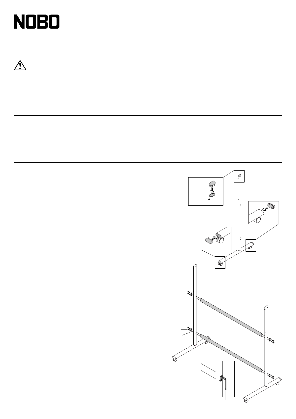
ASSEMBLY OF THE STAND
(1) Push the pipe caps into the front and back of the T-shape legs.
(2 pipe caps)
(2) Push the caps into the tops of the T-shape legs. (2 caps)
(3) Attach the two horizontal bars to the
T-shape legs.
Use hexagonal socket screws and flat washers to attach.
Partially fasten using the supplied hexagonal wrench, then tighten securely after the
upper and lower horizontal bars have been attached.
* Assemble in a flat place.
Frame Cap
Pipe Cap
Pipe Cap
T-shaped leg
Horizontal bar
Hexagonal socket screw
Flat washer
Hexagonal wrench
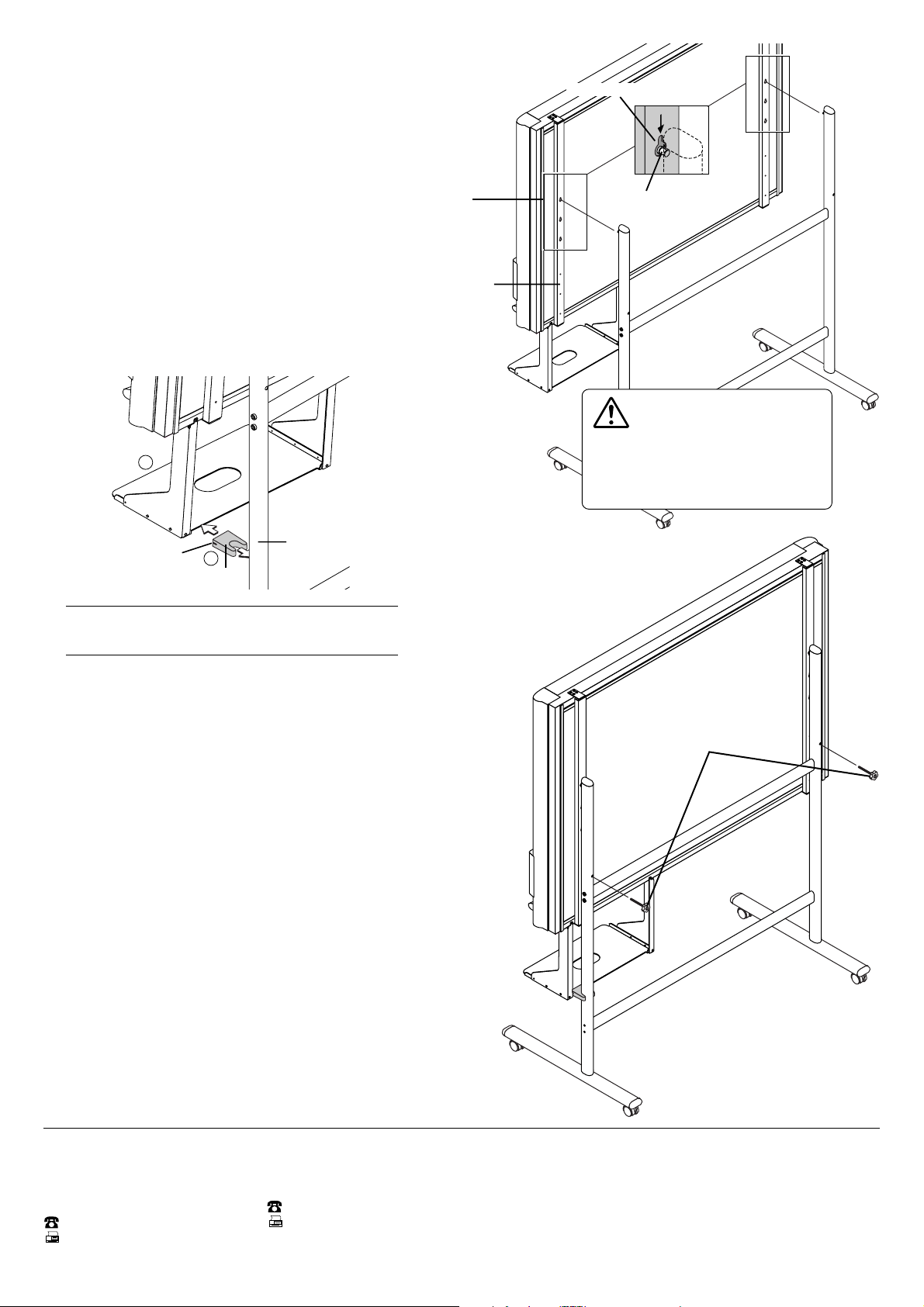
(4) Mount the printer tray to the Copyboard.
Mounting hole
Hook
The rear frame
See Page 9 for information about the assembly and installation of the printer
tray.
*Installation of the printer tray is not required when the Copyboard is
used only for memory storage.
(5) Place the stand’s hooks in the mounting holes in the
support fittings and insert the grooves in the hooks
securely.
There are 3 hole positions. By changing the position, the installation height
can be changed among 3 levels in 100 mm units (1770, 1870, and 1970
mm (the maximum height)).
(6) Insert the stay between the printer tray and
stand.
햲 Tilt the bottom of the main unit slightly forwards and insert
the stay between the printer tray and pipe.
햳 Pushing the main unit back towards the stand, insert the
groove in the stay into the printer tyay.
1
CAUTION
Please have 2 or more persons lift the
Copyboard when installing it or making a
height adjustment. If the unit is dropped or
falls over, this could cause unforeseen injury.
Groove
Note
Check again that the grooves in the stand’s hooks are securely inserted in the mounting holes in the support fittings.
2
Stay
Pipe
(7) Lock the main unit and stand with the two locking
knobs.
Locking knob
ACCO UK & International
Gatehouse Road
Aylesbury
Bucks. HP19 3DT
Great Britain
+44 01296 397444
+44 01296 489539
www.acco.co.uk
ACCO FRANCE
Service commercial & logistique
BP 7, 21601 LONGVIC Cedex
France
+33 (0)3 80 68 60 00
+33 (0)3 80 68 60 48
www.acco.fr
14-2139-03B
 Loading...