

Page 1

NOBOBOARD PPC COLOR
Assembly and Setup Manual
To the Customer
Specialized techniques are required in the wall mounting of the Copyboard. Please do not
attempt any installation work unless you have the techniques.
To the Dealer or Installation Tradesman
In the interest of the safety of the customer, please perform installation work paying due
attention to the strength of the installation location to ensure that it can bear the load of
the Copyboard, printer, and installation parts.
TABLE OF CONTENTS
1. Please Read in the Interest of Safety ........................................................2
2. Packaging List ............................................................................................. 2
3. Copyboard Installation Procedure ............................................................ 3
4. Assembly of the stand ................................................................................ 3
5. Wall Mounting..............................................................................................6
6. Assembly of the Printer Tray ...................................................................... 9
7. Printer Installation .................................................................................... 10
8. Test Print.................................................................................................... 12
9. Fluorescent Lamp Replacement .............................................................. 13
10. Changing the Height of the Unit ............................................... Rear cover
Page 2

PLEASE READ IN THE INTEREST OF SAFETY
Warning
• Please be sure to perform the installation and assembly based on this manual. Incorrect installation or assembly will be the cause of injury.
• Please have 2 or more persons lift the Copyboard when installing or removing it.
•To prevent dropping the strength of the installation location and the anchoring method must fully bear over a
long period the load of the Copyboard, printer, and installation parts. The installation should also be performed
to fully withstand an earthquake. Incorrect installation can result in the Copyboard falling and causing injury.
• Please use M6 or equivalent screws for the wall mounting portion. Use of screws other than M6 or equivalent
can result in the Copyboard falling and causing injury.
• Please mount to a post in the wall or a sturdy wall stud. When the mounting positions of the Copyboard are not
reached, please use optional wall support fittings.
• Please use hardware like anchor nuts and anchor bolts for mounting on a concrete wall.
1. PACKAGING LIST
Please open the carton and check the parts.
In the rare event that something is missing, please contact your store of purchase.
■ Printer package*: One unit
Please check the user’s manual of the printer for a list of contents for the printer package.
■ Copyboard packaging list
Copyboard: 1 unit (standard type or wide type)
Printer tray: Printer tray x1, brackets × 2, M4 screws × 4, M3 screws × 6, Cushions × 2
Wall mounting brackets: × 4, M4 screws × 16 (for wall mounting)
Cable clips: × 3 (for fastening the power cable and USB cable)
Power cable: × 1
Special markers: × 4 (One each of black, red, blue, and green)
Special eraser: × 1
USB cable: × 1
CF card: × 1
A4 test printing paper: 5 sheets
■ Stand packaging list*
T-shape legs (with casters): × 2, horizontal bars × 2, Frame caps × 2, Pipe caps × 4, lock-screws × 2,
hexagonal socket screws × 8, flat washers × 8, hexagonal wrench × 1, stay × 1
* The printer and stand may be options.
2
Page 3
3. COPYBOARD INSTALLATION PROCEDURE
The installation method will change depending on the type of installation. Please perform installation and assembly according to the following procedures.
● When using the stand
Assembly of the stand See Page 3
1
Assembly of the printer tray See Page 9
2
Printer installation See Page 10
3
Test print See Page 12
4
● When mounting to a wall
(Please consult with a dealer or installation tradesman. Installation work should not be done by the customer.
Wall mounting See Page 6
1
Assembly of the printer tray See Page 9
2
Printer installation See Page 10
3
Test print See Page 12
4
* The stand may be an option.
* The printer may be an option.
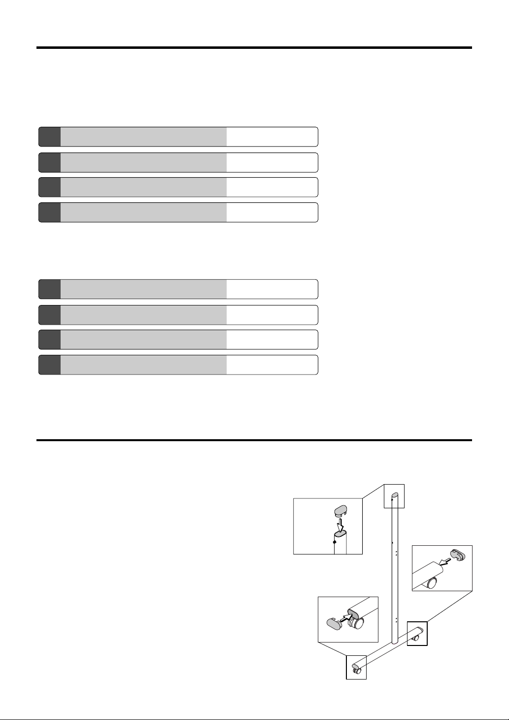
4. ASSEMBLY OF THE STAND
(1) Push the pipe caps into the front and back of the T-shape legs. (2 pipe caps)
(2) Push the caps into the tops of the T-shape legs. (2 caps)
Frame Cap
Pipe Cap
Pipe Cap
3
Page 4
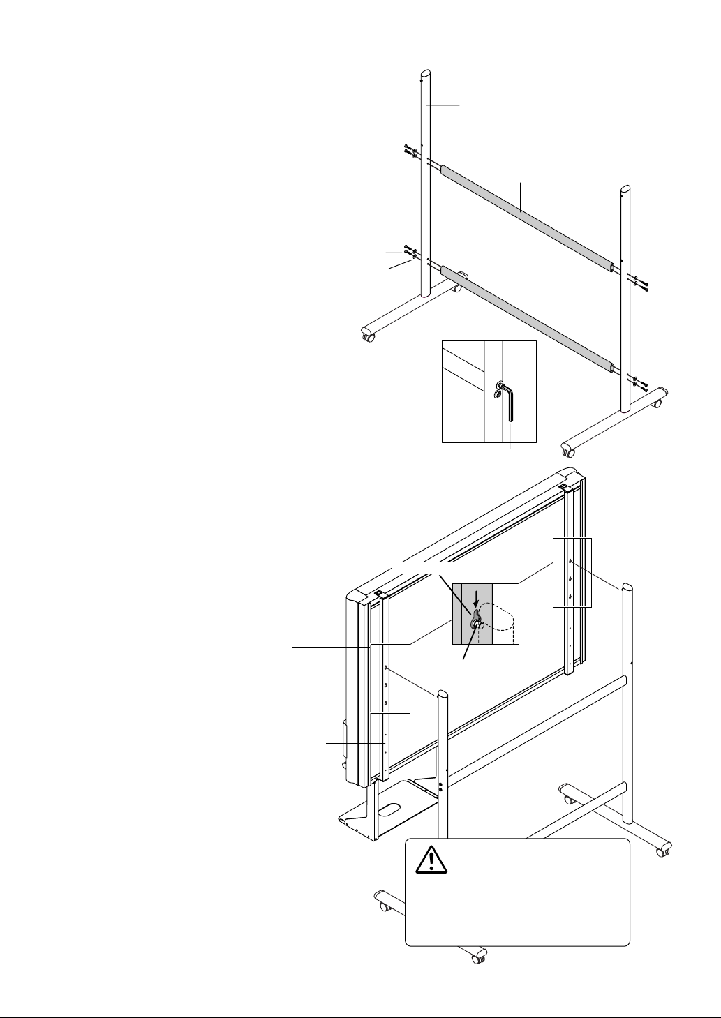
Mounting hole
Hook
The rear frame
(3) Attach the two horizontal bars to the
T-shape legs.
Use hexagonal socket screws and flat washers to
attach.
Partially fasten using the supplied hexagonal wrench,
then tighten securely after the upper and lower horizontal bars have been attached.
Hexagonal socket screw
(4) Mount the printer tray to the Copy-
board.
See Page 9 for information about the assembly and
installation of the printer tray.
* Installation of the printer tray is not required when
the Copyboard is used only for memory storage.
T-shaped leg
Horizontal bar
Flat washer
Hexagonal wrench
(5) Place the stand’s hooks in the mount-
ing holes in the support fittings and
insert the grooves in the hooks securely.
There are 3 hole positions. By changing the
position, the installation height can be
changed among 3 levels in 100 mm units
(1770, 1870, and 1970 mm (the maximum
height)).
CAUTION
Please have 2 or more persons lift the
Copyboard when installing it or making a
height adjustment. If the unit is dropped or
falls over, this could cause unforeseen injury.
4
Page 5
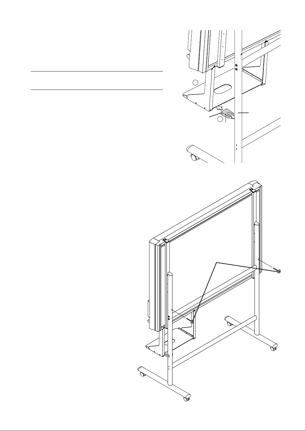
(6) Insert the stay between the printer tray and
stand.
햲 Tilt the bottom of the main unit slightly forwards and insert
the stay between the printer tray and pipe.
햳 Pushing the main unit back towards the stand, insert the
groove in the stay into the printer tray.
Note
Check again that the grooves in the stand’s hooks are securely inserted
in the mounting holes in the support fittings.
1
(7) Lock the main unit and stand with the two
locking knobs.
Groove
Locking knob
Pipe
2
Stay
5
Page 6

5. WALL MOUNTING
(1) Determining the installation location
The diagram indicates the dimensions of the installation positions. The installation position is the same for
both the standard type and the wide type.
The installation of the Copyboard to the wall is performed after the printer tray is assembled and attached
to the Copyboard. See Page 9.
• When the Wall Is Concrete
Embed the commercially available anchor bolts or
anchor nuts for M6 at the installation positions. (See
below)
• When the Wall Structure Is Plywood or
Plaster Board, etc.
Please check that a post or stud is located at the
installation position indicated by the dimensions.
Note
• When the building does not have posts, please use the
stand.
• Separate optional items are available when the standard
wall mounting is not possible, or when installation will be
made to a partition.
1200mm
1077mm
1200mm
Stud, etc.
1077mm
Reference: Installation Method for Various Wall Materials
Please perform an installation that suits the wall material.
Please install the Copyboard to posts or studs when the wall surface is of insufficient strength.
Installation Wall Material
Wooden Walls Wood screws
햲 Make a suitable hole with an auger and 햳
attach the Copyboard with wood screws.
Concrete Walls Anchors
햲 Make a base hole in the wall with a drill. 햳 Insert the anchor. 햴 Fasten the Copyboard
with screws.
Please use a drill of the hole diameter specified for the anchor.
Installation Method
햲햳
햳
Steel Walls Phillips head tapping screws (Pan head)
Check that the steel wall is reinforced and use a drill a hole of suitable
diameter, then attach the Copyboard with tapping screws.
6
햴햲
Page 7

(2) Stick the cushions on the printer tray, then mount the printer tray on the main unit.
햲 Peel off the protective sheets from the cushions’ adhesive surfaces.
햳 Stick the cushions (2) on the back of the bracket.
Protective sheet on
adhesive surface
Cushion
Back of bracket
See page 9 for instructions on assembling and mounting the printer tray.
When mounting the printer tray after installing the main unit on a wall, see page 9.
* There is no need to mount the printer tray when only storing data in the memory card.
Cushions
(3) Attach the 4 supplied wall-mount brackets to the Copyboard using M4 screws.
Wall-mount bracket
M4-screw
7
Page 8

(4) Attaching and anchoring the Copyboard to a wall or wall support fitting.
(The anchoring method will differ depending on the wall mounting method.)
Installing on a Concrete Wall
Anchor nut, etc.
M6 screw
Mounting to a Post
M6 wood screw
8
Page 9

3
6. ASSEMBLY OF THE PRINTER TRAY
(1) Temporarily fasten the right and left brackets to the Copyboard using four M4 screws
in the order of Steps 햲 to 햵.
M4 screws
Front screw hole
2
Right bracket
4
Left bracket
M4 screws
Front screw hole
1
When mounting the printer tray after installing the
main unit on a wall
Use four M4 screws to temporarily fasten the left and right brackets to the four holes in the bottom of the copyboard.
Screws hole
Screws hole
Screws hole
(2) Temporarily fasten the printer tray to the brackets with six M3 screws.
1
Printer tray
2
M3 screw
Should the printer touch on the wall surface, attach the printer tray forward.
Screws hole
Note
If the printer is large, turn the printer tray upside down when mounting.
(3) Securely tighten the screws that were fastened temporarily.
This completes the assembly of the printer tray.
9
Page 10

7. PRINTER INSTALLATION
The installation method for the printer will differ depending on your printer*. Please see your printer manual. An
example of a printer installation is described below.
(1) The USB cable (supplied with the Copyboard) is used to connect the printer connector
of the Copyboard with the USB connector of the printer.
Printer connector
USB connector
USB cable (supplied)
(2) Connect the AC OUTPUT connector of the Copyboard with the printer power connector.
햲 Use the power cable supplied with the printer to connect the AC power connector of the printer with the (220 to 240 V AC)
wall power outlet.
햳 Use the power cable supplied with the Copyboard to connect the AC INPUT connector of the Copyboard with the (220 to
240 V AC) wall power outlet.
AC INPUT connector
햳
Power cable
(Supplied)
Wall power outlet
* The printer may be an option.
AC input connector
햲
Power cable supplied with the printer
10
Page 11

(3) Fasten the power cable and the USB cable with the supplied cable clips.
1.Remove the backing paper from
the rear surface of the clip and
affix the clip at the desired location.
2.Raise the band of the clip, dis-
engage it from the hook, and pull
it out.
3.After finishing the cable
wiring, pass the band end
of the clip through the
guide slot and fasten it by
engaging it on the hook.
Wiring Example
This completes the installation. Please check once again that the screws and connectors are securely fastened.
11
Page 12

8. TEST PRINT
The first time the printer is used, preparations must be performed such as installing the printer cartridge and
removing the protective transportation sheet. Please see your printer manual for details.
(1) Switch on the printer power.
(2) Open the top cover and open the paper tray.
(3) Install the print cartridge in the printer.
(4) Set the supplied test paper on the Copyboard.
(5) Press the POWER button of the Copyboard and switch on the power.
(6) Write or draw a diagram on the sheet surface.
(7) Check that the number of copies indicated in the display window of the Copyboard is “01” and then press the COPY
button.
Black & White printing is selected when the power is switched on. To test colorprinting, press the COLOR button to light the
COLOR indicator and then press the COPY button.
The Copyboard will read a one-screen portion and when this operation stops, the printing operation begins.
This completes the installation of the Copyboard.
12
Page 13

9. FLUORESCENT LAMP REPLACEMENT
This is the replacement method for the white fluorescent lamp that is the light source of the reading device.
When a black band appears at the top and bottom portions of the print or memory storage image, it is time to
replace the fluorescent lamp.
Please inquire with your dealer or ACCO sales office concerning the replacement of the fluorescent lamp.
When replacing the fluorescent lamp, be certain to disconnect the power cable before-
WARNING
hand.
Do not come in contact with the power supply unit inside the Copyboard or other parts.
Doing so will result in electric shock or an accident.
햲 Unplug the power plug of the power cable at
the wall AC outlet.
햳 Remove the rear plate fitting on the back of
the copyboard.
Removal of the 3 screws will release the fittings.
햳
햲
햴 Slide the rear plate about 30 cm to the left.
햵 Replace the fluorescent lamp located at the
right side.
When the replacement has been made, please assemble
the Copyboard by following the procedure in reverse order.
햴
Fluorescent
lamp
햵
13
Page 14

10. CHANGING THE HEIGHT OF THE UNIT
This is the height adjustment to the stand* at the time of setup. The height can be changed among 3 levels in 100
mm units (1770, 1870, and 1970 mm (the maximum height)).
Please lock the casters by pressing the lower portion of the lock buttons of them.
(1) Disconnect the power cable and all other cables.
(2) Take out the printer and remove the printer tray.
Remove the two M4 screws from bottom side of the printer stand and the other two from the rear surface.
(3) Remove the two locking screws (located at the left and right sides).
(4) Change the hole position of the Copyboard rear frame.
The Copyboard will disengage from the hooks when it is lifted up about 1 cm.
Fully hook the (2 left and right) installation holes of the copyboard
rear frame onto the hooks of the stand.
If a stay (for preventing shaking) is mounted on the printer tray,
insert the stay in its original position.
(See (6) on page 5 for mounting instructions.)
(5) Attach the locking screws to the 2 locations (left and
right) and tighten to the rear frames.
(6) Return to original by following the steps in reverse.
Mounting hole
Hook
* The stand may be an option.
The rear frame
CAUTION
Please have 2 or more persons lift
the copyboard when installing it or
making a height adjustment.
If the unit is dropped or falls over, this
could cause unforeseen injury.
14
Page 15

ACCO UK & International
Gatehouse Road
Aylesbury
Bucks. HP19 3DT
Great Britain
+44 01296 397444
+44 01296 489539
www.acco.co.uk
ACCO Polska
Falenty Nowe
ul. Rozy 11
05-090 Raszyn
Polska
022 715 3400
022 720 3458
www.acco.pl
ACCO Benelux
Peppelkade 64
3992 AK Houten
Nederland
030 634 6060
030 634 6070
www.accobenelux.nl
ACCO Deutschland
Hetzel GmbH & Co. KG
Schorndorfer Str. 69
D-73635 Rudersberg-Steinenberg
Germany
+49 0 7183 3003-54
+49 0 7183 3003-52
Email: hotline@accodeutschland.de
www.accodeutschland.de
ACCO Hungária KFT
Ócsai út 4
1239 Budapest
Hungária
+36 1 2 83 16 45
+36 1 2 83 09 28
ACCO Ireland
Clonshaugh Industrial Estate
Clonshaugh
Dublin 17
Republic of Ireland
+353 1 8164300
+353 1 8164302
www.accorexel.ie
ACCO FRANCE
Service commercial & logistique
BP 7, 21601 LONGVIC Cedex
France
+33 (0)3 80 68 60 00
+33 (0)3 80 68 60 48
www.acco.fr
ACCO Italia
10036 Settimo Torinese (TO)
Via Regio Parco 108 / bis
Italy
011 895 1111
011 896 1234
www.acco.it
ACCO Ceská Republika
Hetzel GmbH & Co. KG
Kapitána Sochora 2400
39003 Tábor
Ceská Republika
0 04 20 38 18 94 00
0 04 20 3 61 23 11 05
Acco Ibérica
Carretera Santa
Creu de Calafell, km.9.3
Edifici Centreserveis
08830 Sant Boi de
Llobregat (Barcelona)
+34 93.630.69.21
+34 93.640.97.13
ACCO Nordic
Kanalvagen 10c, 9tr
194 61 Upplands Vasby
Sweden
08 59 00 4244
08 59 00 4110
11
www.accoeurope.com
14-2097-03B
 Loading...