

Noblex NXC1039BT Service Manual
PLL SYNTHESIZER STEREO RADIO WITH
COMPACT DISC PLAYER DIGITAL
MODEL NO :NXC1039BT
NOBLEX

CONTENTS
Page
Disassembly Instructions ......................................................................................................................................3
Disassembly Diagram ...........................................................................................................................................4
Operation Check ...................................................................................................................................................5
Pr i n t e d C i r c u i t B o a r d s .......................................................................................................................................................................................................................................... ...6
Schematic Diagram (Main board)..............................................................................................................................................................................................................9
Sc h e m a t i c D i a g r a m ( K e y b o a r d ) ................................................................................................................................................................................................................11
Electrical Parts List ........................................................................................................................................... .12
Specifications ..................................................................................................................................................... .20
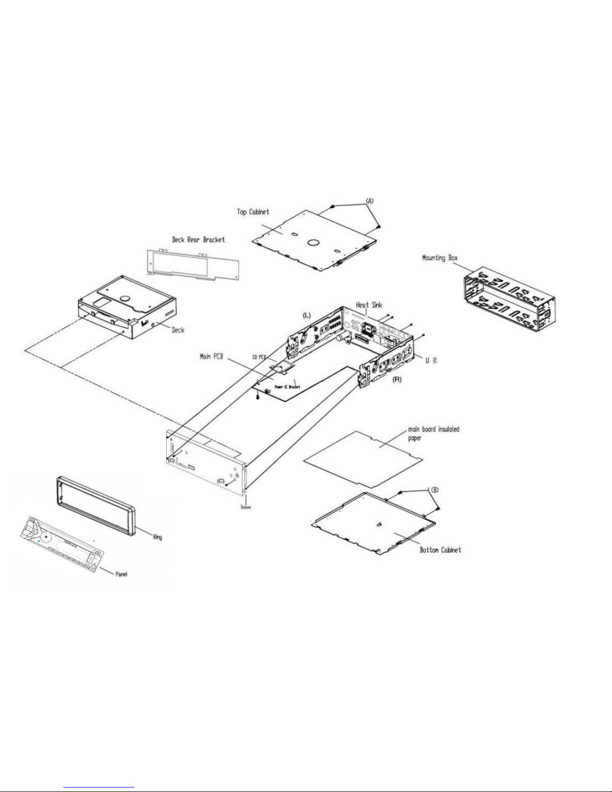

DISASSEMBLY INSTRUCTIONS
1. Using the unlock key that came with the unit or a similar tool, unlock the Mounting Box and remove toward the
rear of the unit.
2. Remove two screws (A) located on the rear of the top cabinet then remove the Top Cabinet.
3. Remove two screws (B) located on the rear of the bottom cabinet then remove the Bottom Cabinet.
4. Take out the Front Panel and the Ring. Remove the screw (C) from on the front side of the Base.
5. Remove two screws (D) and the two screws (E) then remove the deck with the deck brackets from the
Rear-right Cabinet and the heat sink.
6. Remove two screws (G) from under the deck front bracket then remove the Deck Front Bracket.
Remove two screws (H) from under the deck rear bracket then remove the Deck Rear Bracket.
7. Remove two screws (I) from on the left side of the heat sink then remove the Power IC Bracket.
8. Remove two screws (J) from on the left side of the heat sink.
9. Remove two screws (O) from on the rear of the Rear-right Cabinet then remove IC Bracket.
Remote the two screws (L) then to remove the RCA jacks.
10. Remove two screws (M) from each side of the base then remove the Base.
11. Remove the screws (N) from under the main board then remove the Heat Sink, Rear-right Cabinet and
the Main Board.
12. Remove the screw (K) to remove the little hardware.
13. Remove the screw (P) from on the back of the Rear-right then remove antenna Socket.
14. Remove the screw (Q) from right side of the Rear-right bracket then remove the Hexagon Nut.
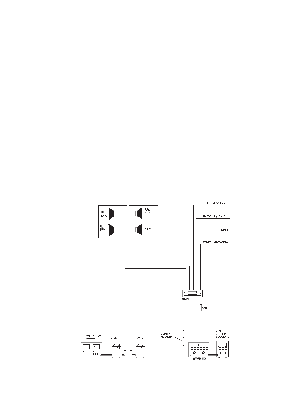
OPERATION CHECK
GENERAL SPECIFICATIONS OF SIGNAL
Standard frequency FM 98.1 MHz (87.5, 108.0 MHz)
MW 1000 kHz (522, 1620 kHz)
Signal output FM 60 dBμV
MW 74 dBμV
Modulation MW 1 kHz 30% MOD.
FM Stereo 1 kHz 75 kHz DEV.
45% for L only or R
only pilot level 10%.
AF output level
Power source voltage
AF load impedance
Balance
Tone
The signal strength read
FM/MW
DC 14.4V (Backup voltage is the same as this)
4 ohm pure resistance
Center position of level
Center position.
in this section is voltage on the antenna.
 Loading...