

Page 1

LCD Television
Service Manual
Chassis: MSD1328
Product: LTDN32k316AM、LTDN42K310WAM
Ver 1.0
Hisense Electric Co.,Ltd.
July,2012
Page 2

Contents
Contents.......................................................................................................................................................................- 2 -
Service Manual ...........................................................................................................................................................- 3 -
1. Precautions and notices.....................................................................................................................................- 3 -
1.1 Warning...................................................................................................................................................- 4 -
1.2 Notes.......................................................................................................................................................- 7 -
2. Product Specifications:...................................................................................................................................- 10 -
2.1Main Board:...........................................................................................................................................- 10 -
2.2 Following products are Chassis MSD1328: .........................................................................................- 11 -
3. Factory/Service OSD Menu and Adjustment..................................................................................................- 12 -
3.1 T o enter the Factory OSD Menu...........................................................................................................- 12 -
3.2 Factory OSD Menu...............................................................................................................................- 12 -
4. Software updating...........................................................................................................................................- 14 -
4.1 Upgrading Mboot software with the ISP-Tool......................................................................................- 14 -
4.2 Upgrading main software with Tftp32、securecrt ...............................................................................- 18 -
4.3 Upgrading with the USB disk...............................................................................................................- 21 -
4.4 Network online updating ......................................................................................................................- 22 -
5. Circuit instruction...........................................................................................................................................- 26 -
5.1 Power assign and block diagram ..........................................................................................................- 26 -
5.2 Main board signal process....................................................................................................................- 27 -
5.3 Troubleshooting....................................................................................................................................- 28 -
6. Schematic circuit diagram..............................................................................................................................- 35 -
7. Explode View..................................................................................................................................................- 35 -
- 2 -
Page 3

Service Manual
1. Precautions and notices
BEFORE SERVICING THE LCD TV, READ THE SAFETY PRECAUTIONS IN
THIS MANUAL.
WHEN REPLACEMENT PARTS ARE REQUIRED, BE SURE TO USE
REPLACEMENT PARTS SPECIFIED BY THE MANUFACTURER.
Proper service and repair is important to the safe, reliable operation of all Hisense
Electric Co., Ltd Equipment. The service procedures recommended by Hisense and
described in this Service Guide are effective methods of performing service operations.
Some of these service operations require the use of tools specially designed for the
purpose. The special tools should be used when and as recommended.
It is important to note that this manual contains various CAUTIONS and NOTICES
which should be carefully read in order to minimize the risk of personal injury to service
personnel. The possibility exists that improper service methods may damage the
equipment. It is also important to understand that these CAUTIONS and NOTICES ARE
NOT EXHAUSTIVE. Hisense could not possibly know, evaluate and advise the service
trade of all conceivable ways in which service might be done or of the possible
hazardous consequences of each way. Consequently, Hisense has not undertaken any
such broad evaluation. Accordingly, a serviceman that uses a service procedure or tools,
- 3 -
Page 4

which are not recommended by Hisense, must first satisfy himself thoroughly that
neither his safety nor the safe of the equipment will be jeopardized by the service
method selected.
Hereafter throughout this manual, Hisense Electric Co., Ltd will be referred to as
Hisense.
1.1 Warning
1.1.1
Critical components having special safety characteristics are identified with a
by the
Ref. No. in the parts list. Use of substitute replacement parts, which do not have the
same specified safety characteristics, may create shock, fire, or other hazards.
Under no circumstances should the original design be modified or altered without
written permission from Hisense. Hisense assumes no liability, express or implied,
arising out of any unauthorized modification of design. Serviceman assumes all liability.
DANGER CAUTION
TO ENSURE THE CONTINUED RELIABILITY OF THIS PRODUCT, USE ONLY
ORIGINAL MANUFACTURER'S REPLACEMENT PARTS, WHICH ARE LISTED WITH
THEIR PART NUMBERS IN THE PARTS LIST SECTION OF THIS SERVICE GUIDE.
1.1.2.
All ICs and many other semiconductors are susceptible to electrostatic discharges (ESD).
Careless handling during repair can reduce life drastically. When repairing, make sure
- 4 -
Page 5

that you are connected with the same potential as the mass of the set by a wristband with
resistance. Keep components and tools also at this same potential.
1. Never replace modules or other components while the unit is switched on.
2. When making settings, use plastic rather than metal tools. This will prevent any
short circuits and the danger of a circuit becoming unstable.
1.1.3
To prevent electrical shock, do not use this polarized ac plug with an extension cord,
receptacle, or the outlet unless the blades can be fully inserted to prevent blade exposure.
To prevent electrical shock, match wide blade or plug to wide slot, fully insert.
1.1.4
When replacement parts are required, be sure to use replacement parts specified by the
manufacturer or have the same characteristics as the original part. Unauthorized
substitutions may result in fire, electric shock, or other hazards.
1.1.5
Safety regulations require that after a repair the set must be returned in its original
condition. In particular attention should be paid to the following points.
-Note: The wire trees should be routed correctly and fixed with the mounted cable
clamps.
-The insulation of the mains lead should be checked for external damage.
1.1.6
(1) Do not touch Signal and Power Connector while this product operates. Do not
- 5 -
Page 6

touch EMI ground part and Heat Sink of Film Filter.
(2) Do not supply a voltage higher than that specified to this product. This may damage
the product and may cause a fire.
(3) Do not use this product in locations where the humidity is extremely high, where it
may be splashed with water, or where flammable materials surround it. Do not install
or use the product in a location that does no satisfy the specified environmental
conditions. This may damage the product and may cause a fire.
(4) If a foreign substance (such as water, metal, or liquid) gets inside the panel module,
immediately turn off the power. Continuing to use the product may cause fire or
electric shock.
(5) If the product emits smoke, and abnormal smell, or makes an abnormal sound,
immediately turn off the power. Continuing to use the product, it may cause fire or
electric shock.
(6) Do not disconnect or connect the connector while power to the product is on. It
takes some time for the voltage to drop to a sufficiently low level after the power has
been turned off. Confirm that the voltage has dropped to a safe level before
disconnecting or connecting the connector.
(7) Do not pull out or insert the power cable from/to an outlet with wet hands. It may
cause electric shock.
(8) Do not damage or modify the power cable. It may cause fire or electric shock.
(9) If the power cable is damaged, or if the connector is loose, do not use the product:
- 6 -
Page 7

otherwise, this can lead to fire or electric shock.
(10) If the power connector or the connector of the power cable becomes dirty or dusty,
wipe it with a dry cloth. Otherwise, this can lead to fire.
(11) Use only with the cart, stand, tripod, bracket, or table specified by the
manufacturer, or sold with the apparatus. When a cart is used, use caution when
moving the cart/apparatus combination to avoid injury from tip-over.
1.2 Notes
Notes on Safe Handling of the LCD panel and during service
The work procedures shown with the Note indication are important for ensuring the
safety of the product and the servicing work. Be sure to follow these instructions.
• Before starting the work, secure a sufficient working space.
• At all times other than when adjusting and checking the product, be sure to turn OFF
the POWER Button and disconnect the power cable from the power source of the TV
during servicing.
• To prevent electric shock and breakage of PC board, start the servicing work at least 30
seconds after the main power has been turned off. Especially when installing and
removing the power board, start servicing at least 2 minutes after the main power has
been turned off.
• While the main power is on, do not touch any parts or circuits other than the ones
specified. If any connection other than the one specified is made between the measuring
- 7 -
Page 8

equipment and the high voltage power supply block, it can result in electric shock or
activation of the leakage-detection circuit breaker.
• When installing the LCD module in, and removing it from the packing carton, be sure
to have at least two persons perform the work.
• When the surface of the panel comes into contact with the cushioning materials, be
sure to confirm that there is no foreign matter on top of the cushioning materials before
the surface of the panel comes into contact with the cushioning materials. Failure to
observe this precaution may result in, the surface of the panel being scratched by foreign
matter.
• When handling the circuit board, be sure to remove static electricity from your body
before handling the circuit board.
• Be sure to handle the circuit board by holding the large parts as the heat sink or
transformer. Failure to observe this precaution may result in the occurrence of an
abnormality in the soldered areas.
• Do not stack the circuit boards. Failure to observe this precaution may result in
problems resulting from scratches on the parts, the deformation of parts, and
short-circuits due to residual electric charge.
• Routing of the wires and fixing them in position must be done in accordance with the
original routing and fixing configuration when servicing is completed. All the wires are
routed far away from the areas that become hot (such as the heat sink). These wires are
fixed in position with the wire clamps so that the wires do not move, thereby ensuring
- 8 -
Page 9
that they are not damaged and their materials do not deteriorate over long periods of time.
Therefore, route the cables and fix the cables to the original position and states using the
wire clamps.
• Perform a safety check when servicing is completed. Verify that the peripherals of the
serviced points have not undergone any deterioration during servicing. Also verify that
the screws, parts and cables removed for servicing purposes have all been returned to
their proper locations in accordance with the original setup.
The lightning flash with arrowhead symbol, within an equilateral
triangle is intended to alert the user to the presence of uninsulated
dangerous voltage within the products enclosure that may be of sufficient magnitude to
constitute a risk of electric shock.
The exclamation point within an equilateral triangle is intended to alert
the user to the presence of important operating and maintenance (servicing)
instructions in the literature accompanying the set.
- 9 -
Page 10
2. Product Specifications:
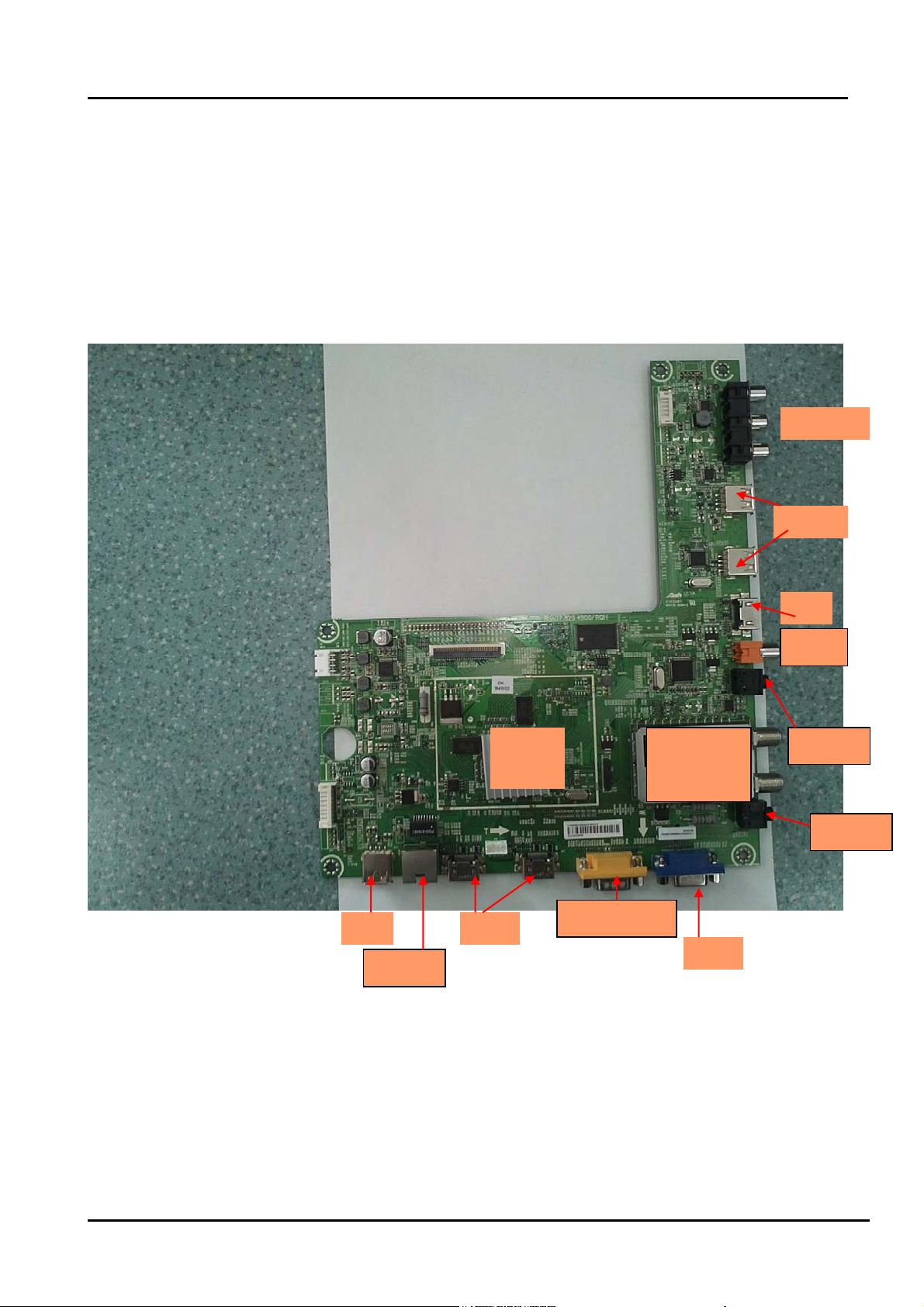
2.1Main Board:
Take LTDN32k316AMmain board(4900)for example:
Top
AV OTU
HDMI
USB
Coaxial
IC
MSD1328
Tuner
Cable Air
Earphone
PC Audio
USB HDMI
Ethernet
Comp/AV1/AV2
VGA
- 10 -
Page 11
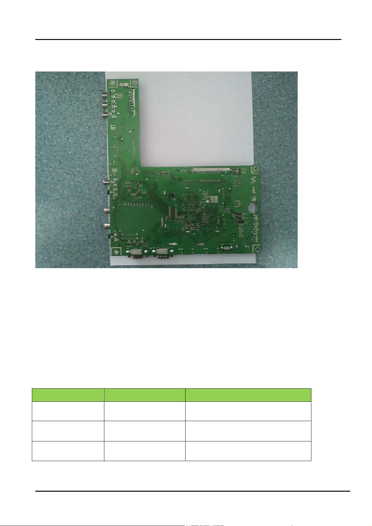
Bottom:
Note
Above “Main board image”is only for LTDN32k316AM, other products please look for the actual
units to determine the boards.
:
2.2 Following products are Chassis MSD1328:
Model Panel Mode LVDS(Main-Panel)
LTDN32k316AM HE315FH-E58\PW1\ROH FFC-30-367\ROH
LTDN42K310WAM
HE420FF-B57(1000)\ROH HX2-2x22KLB450P-CMO\ROH
- 11 -
Page 12

3. Factory/Service OSD Menu and Adjustment
3.1 To enter the Factory OSD Menu
a. With factory RC (remote control)
1. Press “M” button and enter factory mode.(Note1)
2. Press “Menu” button and enter factory OSD menu.
3. Press “CH+”/“CH-” button select the function menu, press “VOL+”/“VOL-” enter the selected
function menu. Press “VOL+”/“VOL-” button adjust values in the menu.
4. Press “M” button exit factory mode in the factory OSD menu.
When TV outgoing factory, user can not enter factory OSD menu with Factory Remote
Note:
1. In the “Factory Menu”, item “Function”->”TOFAC” ,you can select “M” or “U”, default is “U”.
----M-Means you can enter factory mode with factory RC or user RC.
----U-Means you can enter factory mode only with user’s RC.
2. Mode “M” is only used for factory production.
b. With user’s RC
Power on the TV.
1. Press “Menu” button and call up User OSD Menu.
2. Select “ Sound” -> “Balance” item.
3. Press number key 1->9->6 ->9 in sequence when “Balance” item is focused.
Note: If necessary, re-do number keys.
4. Factory OSD appears.
Note: Press the standby button then AC turn off and restart the TV, which can exit factory OSD menu.
3.2 Factory OSD Menu
The Factory OSD Menu comprises Factory Menu and Design Menu .
3.2.1、Factory Menu
- 12 -
Page 13

Factory Menu
White Balance
Auto Calibration
Option
Init
Test Pattern
Version
White Balance
R-DRV:
G- DRV:
B- DRV
R-CUT:
G- CUT:
B- CUT:
Color Temp: Medium
Panel Set : B1
Option
TO FAC : M or U
LOGO: Hisense
OSD language: English
Power Mode Memory
Set MAC_ADDR
PVR_RecordALL Off
HDCP EEP
Uart enable On
WDT On
C1 Key Null
3.2.2、Design Menu
Design Menu
Picture Mode
Audio Mode
Picture Curve
Audio Curve
SSC Adjust
Saving Mode
Overscan
Not Stand
Note:
The above “Factory/Service OSD Menus” are re ference on ly, please ref er to t he ac tual unit
to determine the appearances.
- 13 -
Page 14
4. Software updating
Software Upgrading includes MBoot and main software. Usually first update MBoot then main
software. With ISP_Tools、Tftp and SecureCRT upgrading Tools.
4.1 Upgrading Mboot software with the ISP-Tool
4.1.1 Hardware connecting
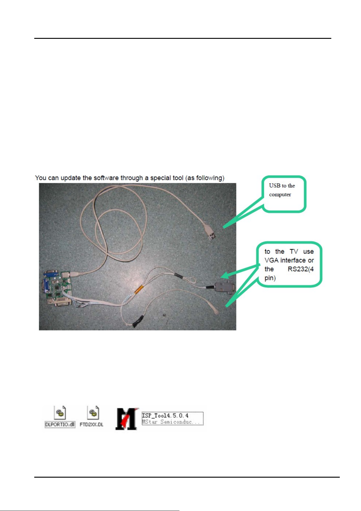
You can update the software through a special tool (as following)
Connect the Debug board to the TV use the RS232 (4 pin), the other USB port to the PC.
4.1.2 Install the ISP_TOOL4.5.0.4-------only for the first time update.
1、The software is upgraded by a burning tool- ISP_TOOL.exe
2、Find the folder where the ISP_TOOL4.5.0.4 lies in.
There are three folders/files in this folder together.
DLPORTIO.dll and FTD2XX.DLL must be in the same folder
- 14 -
Page 15
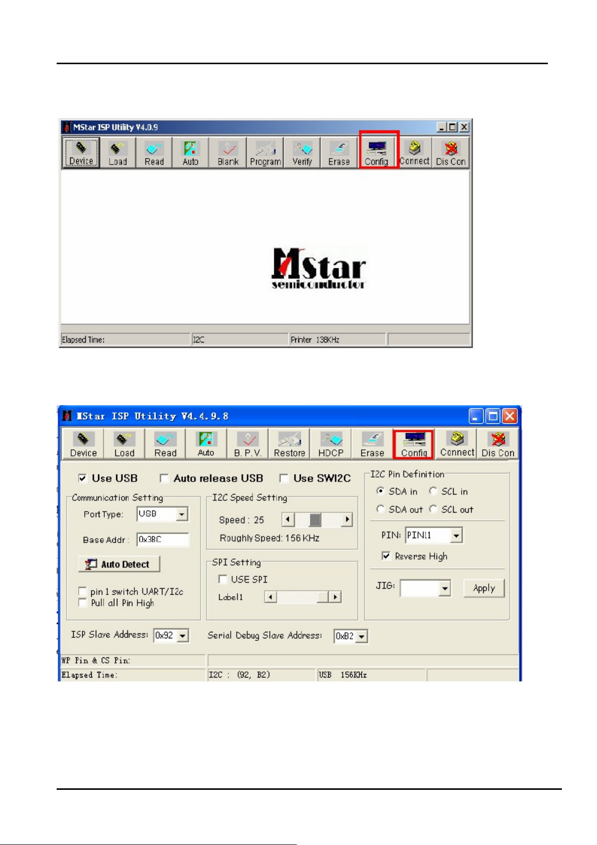
3、Double click the ISP_TOOL4.5.0.4 icon, and then a dialog window will show as below.
4、Click the” Config “button. And then a dialog window will show as below.
Draw on the front of “Use USB”
Port Type setting is USB
Base Addr setting is 0x38C
ISP Slave Address choose 0x92
Serial Debug Slave Address choose 0xB2,
- 15 -
Page 16

5、Click the “Connect”button,if appear the following figure, It indicates that the ISP_TOOL has
connected.(According to the tv set,”Device Type” maybe different.)
If appear the following figure,It indicates that the ISP_TOOL has not connected. Please click
the“DisCon”button and “Connect”button to connect..
6、Click the“Read ”button,Choose the correct update file。
- 16 -
Page 17

7、After the update file has been chosen successfully。
Click the“Auto”button and choose parameters as following。
8、Click the “Run” button and wait update end.
If show any error message ,then do “Dis Con” >> “Connect”,and click the “Run” button
again,till show the following dialog window.
- 17 -
Page 18

4.2 Upgrading main software with Tftp32、securecrt
a) Run Tftpd32.exe. Browse the Base Directory file “*_dtv.a7”
Settings as following, late click “OK”.
b) Run Securecrt.exe to set up a serical seccion.
Select FileConnectNew seccion
- 18 -
Page 19

AC power off the TV, this time the mouse must lies on the Securecrt interface. then AC
power on the TV, at the same time press “enter” key. you will see“<<mstar>>#”on the
Securecrt interface.
(the following image).
Next input : set ipaddr 192.168.5.200;set serverip 192.168.5.211;saveenv ,then press
- 19 -
Page 20

“enter” key. late input: “mstar mscript/auto_update.txt”to update (the following
image).note1
After software update has finished, the TV OSD appears following.
Note:
1) Serverip “192.168.5.211”is PC LAN IP address. When update the main software,you
must replace you PC IP address with 192.168.5.211,and net mask with 255.255.255.0 .
- 20 -
Page 21

4.3 Upgrading with the USB disk
4.3.1 TV in normal state
1. Copy the “USBUpgrade.bin” file that MBoot and main software named to the root directory of
two USB disks respectively.
2. Insert the USB disk into the USB slot of the TV SET.
3. Press “Menu” button of remote control and call up User OSD Menu, choose " OPTION
"->”Software Update(USB)” item.
- 21 -
Page 22

4. Press “OK”, it will show a confirm message box, Press [◀] button to select “yes” in the
confirm message box, TV will restart and start automatic update.
5. Then it will update the software automatically, Please don’t power off during the updating
process.
6. After update succeeds, TV SET will restart automatically.
7. First update the MBoot software, second update the main software. In order to convenience,
prepare two USB disks to save different software respectively.
4.3.2 TV in abnormal state
If the method of 4.3.1 can not update successfully or TV can not power on normally . You will
adopt the force update method. Insert the USB disk with USBUpgrade.bin into the USB slot of
the TV. AC power on the TV , at the moment ,press the” menu “key of TV keypad. Longer about
5 seconds. Then the TV will automatically update. If defeat, try again.
Note:
After updating, you must confirm the software version in the “Factory Menu” and you'd better
do a " UnProtected Clear" in the “Factory Menu”.
4.4 Network online updating
First, correctly connect network. Open the network setting image. “MENU””OPTION”
Second, Press right or OK key to enter the subpage of network settings menu. And select
“Network Upgrade” item and then press “OK” key to download the new firmware.
- 22 -
Page 23

Third, Checking if there is new firmware..
If there is new firmware on our server, you will see the dialog below and press arrow to
continue firmware download..Note2
- 23 -
Page 24

Next
This time download has finished, next to automatically update the firmware.
Note:
1) It will take sometimes to complete the upgrade. The time depend on your network speed.
- 24 -
Page 25

Don’t Turn off TV during upgrading.
2) If there is no new firmware on our server, see the dialog below.
3) If there is no network or not correctly connected it. See the below dialog below.
- 25 -
Page 26

5. Circuit instruction
5.1 Power assign and block diagram
- 26 -
Page 27

5.2 Main board signal process
- 27 -
Page 28

5.3 Troubleshooting
5.3.1 Troubleshooting for Remote Control
Remote control does not work
Try new batteries
NO
Replace RC
Check IR receiver
YES
YES
Replace battery
Replace remote control
Change Led & IR board
NO
Change Led & IR cable
NO
Replace main board
YES
Replace Led & IR BD
YES
Replace Led & IR cable
- 28 -
Page 29

5.3.2 Troubleshooting for Function Key
Buttons does not work
Check switches
YES
Check solder connections and
see if any switches are stuck.
NO
Check key board
NO
Check Key BD cable
YES
Replace Key BD
YES
Change Key BD
OK
NO
Replace main board
- 29 -
Page 30

5.3.3 TV won’t Power On
TV won’t power on
Is LED
light?
NO
Check Power
Output
YES
Make Sure Power
source is live
YES
NO
BLUE
RED
Panel Bright
NO
YES
Check signal
Source
YES
NO
Check Power
Cord
NO
Try Power on by
RC and Button
Neither
works
Replace Main
BD
YES
Only
one works
Both
Work
Replace
Power Cord
Check/replace IR
BD or Keypad
PCA
NO
(to contact Hisense tech support.)
Replace Main BD
Replace Panel
OK
YES
Power on
NO
Replace Power BD
YES
OK
- 30 -
Page 31

5.3.4 Troubleshooting for Audio
No sound
Check connecter
YES
Reconnect
NO
Check speaker wire
NO
Check speaker set
YES
YES
Replace speaker wire
Replace speaker set
NO
Replace main board
NO
YES
OK
Power Supply Board
- 31 -
Page 32

5.3.5 Troubleshooting for TV/VGA/HDMI input
No picture on the screen
NO
Check Signal Source
Make sure signal
source is available
YES
Check connect
NO
YES
Check cab l e
NO
Replace main board
Reconnect
Replace cable
- 32 -
Page 33

5.3.6 Troubleshooting for YPbPr input
No picture on the screen
Check Source work or not
YES
Check connect
NO
Check Wires (Green Blue, Red)
NO
Replace main board
NO
YES
YES
Check Source Device
Reconnect
Replace wires
- 33 -
Page 34

5.3.7 Troubleshooting for Video input
No picture on the screen
Check Source work or not
YES
Check connect
NO
Check Cable/ Wires
NO
Replace main board
NO
YES
YES
Check Signal Source
Reconnect
Replace Cable/Wires
- 34 -
Page 35

6. Schematic circuit diagram
7. Explode View
- 35 -
Page 36

XP801XP801
VD815
VD815
R861
R861
680R
680R
C850
C850
470n/63V
470n/63V
1
C932
C932
10u/350V
10u/350V
R974
R974
10R
10R
STB
470p/1KV
470p/1KV
C857
C857
470n/50V
470n/50V
R8581kR858
1k
C855
C855
1 2
MUR460G
MUR460G
R850
R850
68R/3W
68R/3W
NA 100n/100V
NA 100n/100V
R859
R859
NA 100k/2W
NA 100k/2W
1
3
VD817
VD817
MBRF20H100CTG
MBRF20H100CTG
1000u/25V
1000u/25V
R899
R899
4.7k
4.7k
C939
C939
220n/250VV
220n/250VV
W924W924
C831
C831
C851
C851
W919W919
R958
R958
6.2k
6.2k
C853
C853
68u/250V
68u/250V
12V
L805
L805
2
LEI-200B
LEI-200B
C858
C858
C854
C854
1000u/25V
1000u/25V
1000u/25V
1000u/25V
R959
R959
12k
12k
VD829
VD829
12
1N4148W
1N4148W
R898
R898
6.2k
6.2k
1
2 3
C878
C878
R895
R895
100n/50V
100n/50V
4.7k
4.7k
4
3
XP903XP903
2
2
1
1
XP901XP901
C804
C804
220n/AC275V
RT801
RT801
SCK10054LSY505
RV801
RV801
Q805
Q805
V801
V801
v801
v801
SCK10054LSY505
220n/AC275V
220n/AC275V
Q804
Q804
1
1
2
2
3
3
4
4
C803
C803
1 2
1 2
1 2
L803
L803
L806
L806
L809
L809
LCL-3505-HP
LCL-3505-HP
LCL-2508
LCL-2508
LCL-008-F\ROH
LCL-008-F\ROH
F801
F801
2
1
12
TVR10621KSKNY
Q803
Q803
VD817
VD817
TVR10621KSKNY
1
2
3
4
TR53821400
TR53821400
220n/AC275V
R801
R801
34
34
34
680k
680k
R802
R802
680k
680k
R803
R803
680k
680k
G805G805
G808G808
1
1
C801
C801
470p/AC400V
470p/AC400V
1 2
1 2
1 2
C802
C802
470p/AC400V
470p/AC400V
L804
L804
L807
L807
L808
L808
LCL-2508
LCL-2508
LCL-3505-HP
LCL-3505-HP
LCL-008-F\ROH
LCL-008-F\ROH
R819
R819
NA 150K
NA 150K
R806
R806
680k
680k
R807
R807
680k
680k
R811
R811
270k
270k
W921W921
34
34
34
12
1 2
VD804
VD804
R208
R208
C845
C845
10n/1KV
10n/1KV
2 34
100V
R905
R905
200k
200k
100n/50V
OVP
C942
C942
0R
R10080RR1008
100n/50V
W926W926
SW1
C943
C943
1u/50V
1u/50V
R10060RR1006
0R
W925W925
1n/50V
1n/50V
C941
C941
R908
R908
R907
R907
200k
200k
W920W920
8.2k
8.2k
12V_VCC
0R
R10050RR1005
100n/50V
100n/50V
OUT
VD807
VD807
R208
R208
VD806
VD806
R208
R208
V800
V800
BCP56-10T1G
BCP56-10T1G
1
1 2
VZ801
VZ801
MSZ16T1G
MSZ16T1G
C940
C940
12
C841
C841
10n/1KV
10n/1KV
1
4
5
6
7
8
C807
C807
470p/1KV
470p/1KV
12
1 2
C812
C812
470p/1KV
470p/1KV
R8081kR808
1k
VCC
C820
C820
100n/100V
100n/100V
L901
L901
LEI-302B
LEI-302B
N901
N901
CT
FLAG
OV2SHDN
UVLO3FB
EN
SSCOMP
VIN
VCC
OUT
GND
FAULT
HL3051_AP3041
HL3051_AP3041
C861
C861
47u/50V
47u/50V
SC
CS
RT
VD808
VD808
R208
R208
VD805
VD805
R208
R208
16
15
14
13
12
11
10
9
R987NAR987
NA
R983
R983
39k
39k
R982
R982
150k
150k
PWM
R10030RR1003
T801
T801
T802
V902
V902
1
1
12
R813
R813
10R
10R
VD822
VD822
FR104
FR104
1
23
W917W917
R993
R993
510k
510k
R996
R996
510k
510k
R995
R995
220k
220k
2
3
3
2
R973
R973
10R
10R
R10040RR1004
0R
T802
BCK-04HE
BCK-04HE
BCK-80-TM0047CQ
BCK-80-TM0047CQ
VCC
C862
C862
470n/63V
470n/63V
R851
R851
330R
330R
N807
N807
KA431AZutctl431
KA431AZutctl431
2 3
C933
C933
1n/50V
1n/50V
V903
V903
FDU3N40
FDU3N40
R985
R985
R972
R972
10R
10R
10R
10R
C848
1 2
2
3
C856
C856
47u/100V
47u/100V
R847
R847
0.33R/2W
0.33R/2W
W818W818
4
C843
C843
10n/50V
10n/50V
PC817BHS817BH11A817B
PC817BHS817BH11A817B
2.2n/AC400V
2.2n/AC400V
1 2
MUR160
MUR160
1 2
MUR160
MUR160
R9261RR926
1R
C935
C935
10n/50V
10n/50V
0R
C848
2.2n/1KV
2.2n/1KV
N808
N808
C840
C840
VD905
VD905
VD904
VD904
OVP
R994
R994
10k
10k
AOD3N50
AOD3N50
R960
R960
51k
51k
R10070RR1007
R835
R835
100k/2W
100k/2W
C810
C810
C809
C809
68u/450V
68u/450V
R848
NA 1N4148W
NA 1N4148W
FB
GND
MBR0520
MBR0520
NA VD831
NA VD831
VD820
VD820
1
2
3
4
12
R848
68R
68R
R1001
R1001
5.1k
5.1k
R922
R922
1R NA
1R NA
68u/450V
68u/450V
C847
C847
R846
R846
1n/50V
1n/50V
10k
10k
N801
N801
8
HV
Skip/latch
7
01
VCC6CS
5
R9991kR999
1k
C947
C947
1n/50V
1n/50V
OUT
R968
R968
220R
220R
C945
C945
100n/50V
100n/50V
10n/50V
10n/50V
Drv
NCP1271D65R2G
NCP1271D65R2G
R986
R986
NA 22R
NA 22R
C944
C944
R979
R979
47R
47R
R997
R997
22R
22R
C822
C822
100n/50V
100n/50V
0R
R843
R843
12
NA 5.1R
NA 5.1R
R849
R849
R8443kR844
3k
C844
C844
100p/50V
100p/50V
W817W817
1
R9690RR969
0R
VD813
VD813
RG1C
RG1C
V801
V801
STK0765BF
STK0765BF
1
10k
10k
1 2
VZ802
VZ802
MSZ16T1G
MSZ16T1G
W916W916
L902
L902
TEM2011
TEM2011
3
V901
V901
AOD3N50
AOD3N50
2
R9981RR998
1R
R975
R975
220k
220k
R984
R984
220k
220k
R976
R976
220k
220k
R971
R971
100k
100k
C852
C852
100n/50V
100n/50V
R924
R924
12k
12k
V917
V917
MMBT2222A
MMBT2222A
100V
VZ806
VZ806
MSZ16T1G
MSZ16T1G
SW
PWM
R8632kR863
2k
MMBT2222A
MMBT2222A
R864
R864
10k
10k
V911
V911
12
R909
R909
20k
20k
R8652kR865
2k
1
12V_VCC
R9701kR970
1k
C875
C875
100n/50V
100n/50V
2 3
C859
C859
100n/50V
100n/50V
R868
R868
5.1k
5.1k
R977
R977
24k
24k
R978
R978
24k
24k
100p/50V
100p/50V
C876
C876
R9811kR981
1k
1
W814W814
W915W915
R967
R967
100k
100k
R961
R961
24k
24k
R980
R980
24k
24k
1
V918
V918
MMBTA42
MMBTA42
2 3
XP902XP902
W923W923
7
STB
6
5
4
3
2
1
23
V912
V912
MMBT2907ALT1
MMBT2907ALT1
R9391kR939
1k
R942
R942
51k
51k
SW1
C914
C914
100n/50V
100n/50V
Page 37

5
LTDN32k316AM<DN42K310WAM main board:4900
4
3
2
1
TO Inverter Board
100n/16V/NCC5100n/16V/NC
R443 0R/NCR443 0R/NC
R409
R409
10k/NC
10k/NC
C34
C34
100n/16V
100n/16V
N11
N11
3
2
C43
C43
100n/16V
100n/16V
LD1117A-3.3AZ1117H-3.3/NC
LD1117A-3.3AZ1117H-3.3/NC
AP1084D33GAZ1084D-3.3
AP1084D33GAZ1084D-3.3
3
C53
C53
100n/16V
100n/16V
3
C86
C86
100n/16V
100n/16V
3.3Vstb
R50
R50
0R/NC
0R/NC
R60RR6
0R
R12
R12
1
4.7k/NC
4.7k/NC
C5
R54
R54
0R/NC
0R/NC
R18 10kR18 10k
100n/16V/NCC9100n/16V/NC
C292
C292
100n/16V
100n/16V
+3.3V
R440
R440
10k
10k
R439 10kR439 10k
3
V29
V29
1
2SCR523EB
2SCR523EB
2
C291
C291
100n/16V
100n/16V
N12
N12
VOUT
VIN
Vout
Vin
VOUT
ADJ
ADJ
1
1
VOUT
VIN
VOUT
ADJ
LD1117A-2.5AZ1117H-2.5
LD1117A-2.5AZ1117H-2.5
1
VOUT
VIN
VOUT
ADJ
LD1117A-2.5AZ1117H-2.5
LD1117A-2.5AZ1117H-2.5
1
N15
N15
N16
N16
R417 22kR417 22k
R1
4.7k/NCR14.7k/NC
R7 10kR7 10k
V1
V1
2SCR523EB/NC
2SCR523EB/NC
2 3
R418
R418
47k
47k
4
3
2
4
2
Power Input
兼容老电源板规范接口标准
XP18XP18
1
2
XP1XP1
5Vstb
R434
R434
10k
10k
V6
2SCR523EB V62SCR523EB
2 3
STPB2012-121PT/NC
STPB2012-121PT/NC
3
4
1
2
3
4
5
BL-ON/OFF
6
7
8
9
10
11
12
STANDBY
13
INV_12V
R59
R59
4.7k
4.7k
5Vstb
+12V_S
for 32" 37" only
for 40"/46"/55"
5Vstb
for 32" 37" only
+5V
for 40"/46"/55"
D D
C C
B B
For 32"/37"
7
6
5
4
BL-ON/OFF
3
2
1
XP2XP2
POWER_SW
HI = > OFF
LO = > ON
STANDBY
R210R R210R
BL-ADJUST
INV_12V
+12V
+5V_S
INV_12V
R444
R444
47k
47k
R435
R435
0R/NC
0R/NC
R442
R442
4.7k
4.7k
L37
L37
L41
L41
L38
L38
L39
L39
1
STPB2012-121PT
STPB2012-121PT
STPB2012-121PT/NC
STPB2012-121PT/NC
STPB2012-121PT
STPB2012-121PT
C515
C515
10u/16V
10u/16V
VVV
R15 0RR15 0R
+12V
STPB2012-121PT
STPB2012-121PT
1
STPB2012-121PT
STPB2012-121PT
BL-ADJUST
5Vstb
L59
L59
100n/16V
100n/16V
L36
L36
R53
R53
4.7k
4.7k
+12V
C514
C514
10u/16V
10u/16V
C140
C140
V8
2SCR523EB V82SCR523EB
2 3
Power Input
新电源板规范接口标准
BL-ADJUST BL-ON/OFF
STANDBY
5Vstb
C137
C137
R291
R291
22k
22k
100n/16V
100n/16V
R60
R60
10k
10k
C129
C129
100n/16V
100n/16V
1
R102
R102
47k
47k
R229
R229
10k
10k
V7
2SCR523EB V72SCR523EB
2 3
C132
C132
100n/16V
100n/16V
1
2
3
XP20XP20
1 2
3
R270R R270R
5
7
9
11
5Vstb
C13
C13
10u/10V
10u/10V
N40
N40
S1
D11
G1
D12
S2
D21
G24D22
IRF7314/AO4801/3
IRF7314/AO4801/3
C12
C12
100n/16V
100n/16V
8
7
6
5
Standby
VBLCTRL-P2
4
6
INV_12V
8
10
VVVVVV
12
+12V
C90
C90
C210
10u/16V
10u/16V
C210
C211
C211
C320
C320
10u/16V
10u/16V
100n/16V
100n/16V
100u/16V/NC
100u/16V/NC
STANDBY
100n/16VC3100n/16V
STANDBY:
HIGH->NORMAL
LOW->STANDBY
C3
5Vstb 3.3Vstb
R2
R9 100RR9 100R
R13
R13
4.7k/NC
4.7k/NC
4.7kR24.7k
V3
2 3
2SCR523EB V32SCR523EB
R10
R10
4.7k
4.7k
1
C6
100n/16V/NCC6100n/16V/NC
R3
10kR310k
V4
2 3
2SCR523EB V42SCR523EB
R11
R11
0R/NC
0R/NC
R14
R14
1
4.7k
4.7k
C7
4.7u/10V/NCC74.7u/10V/NC
R4
10kR410k
POWER_SW 2
1.2V FOR 1328BX CORE POWER
STPB2012-121PT/NC
STPB2012-121PT/NC
+5V
L16
L16
+12V
L7
L7
STPB2012-121PT
C10
C10
100n/16V
100n/16V
10u/16V
10u/16V
STPB2012-121PT
C26
C26
10u/16V
10u/16V
R20 220kR20 220k
+5V
STANDBY
C230 100n/16VC230 100n/16V
R22 100kR22 100k
R24 100k/NCR24 100k/NC
C25
C25
100n/16V
100n/16V
C29
C29
+5V
+12V
N8
1
SW
IN
8
BYP
FREQ
6
BST
EN
7
GND
FB
MP1492 N8MP1492
3
5
4.7u/10V
4.7u/10V
4
1u/25V
1u/25V
2
VCC_VSENSE3
L8 2.2 uHL8 2.2 uH
R35
R35
R330RR33
C30
C30
C31
C31
180k
180k
0R
R34
R34
22R
22R
C32
C32
1n/50V
1n/50V
VCC_VSENSE
C414
C414
220p/50V
220p/50V
C231
C231
100n/16V
100n/16V
R920RR92
R171 100RR171 100R
R36 16.9kR36 16.9k
R37
R37
36k
36k
0R
VCC1V
C232
C232
C28
C28
22u/6.3V
22u/6.3V
22u/6.3V
22u/6.3V
C413
C413
100n/16V
100n/16V
R38
R38
10k/NC
10k/NC
VBLCTRL-P22
BRI_ADJ-PWM2
BRI_ADJ-PWM22,8
Power for Panel
L13 STPB2012-121PTL13 STPB2012-121PT
+12V
L14
L14
+5V
STPB2012-121PT/NC
STPB2012-121PT/NC
H:OFF
L:ON
1 2
L9
L9
R4111kR411
1k
VD2
VD2
MBR0520LT1/B0520LW
MBR0520LT1/B0520LW
C33
C33
2.2u/10V
2.2u/10V
ON_PANEL2
3.3V Power_Standby only for AVDD_MPLL and IR
5Vstb
BLM18PG181SN1/NC
BLM18PG181SN1/NC
CORE POWER 1.2V, 1.16V<=VDDC<=1.24V
1.5V Power_DDR3(1105681)
C39
C39
22u/6.3V
22u/6.3V
L3 4.7 uHL3 4.7 uH
R23
R23
22R/NC
22R/NC
C18
C18
+1.5V_DDR3
C40
C40
22u/6.3V
22u/6.3V
C41
C41
100n/16V
100n/16V
C16
C16
330u/6V/NC
330u/6V/NC
C47
C47
22u/6.3V
22u/6.3V
3.3V Power_Normal
+5V
L11
L11
BLM18PG181SN1
BLM18PG181SN1
C42
C42
2.2u/10V
2.2u/10V
2.5V FOR 1328BX
+5V
L12
+5V_S
R26
R26
C66
C66
130k
130k
22p/50V
22p/50V
R25
R25
R136
R136
22k
22k
10k/NC
10k/NC
C513
C513
220u/16V/NC
220u/16V/NC
C14
C14
22u/6.3V
22u/6.3V
C22
C22
22u/6.3V
22u/6.3V
C21
C21
100n/16V
100n/16V
C15
C15
22u/6.3V/NC
22u/6.3V/NC
L12
BLM18PG181SN1
BLM18PG181SN1
+5V
L15
L15
BLM18PG181SN1
BLM18PG181SN1
C52
C52
2.2u/10V
2.2u/10V
2.2u/10V
2.2u/10V
C92
C92
+12V_S
L4
L4
STPB2012-121PT
STPB2012-121PT
+5V
R40 2R/2WR40 2R/2W
+5V FOR SYS
C19
C19
10u/16V
10u/16V
C20
C20
C17
C17
100n/16V
100n/16V
10u/16V
10u/16V
+5V_S
10n/50V
10n/50V
N10
3
2.2u/10V/NC
2.2u/10V/NC
EN
PG
VIN
C46
C46
10
11
12
7
6
3
8
N10
4
VOUT
2
VOUT
ADJ
1
Vout=0.765*(1+R1/R2)
C64 100n/25VC64 100n/25V
C508 100n/16VC508 100n/16V
R127 100kR127 100k
R165 100k/NCR165 100k/NC
1 2
R167
R167
LM3Z5V6T1G
LM3Z5V6T1G
100k/NC
100k/NC
VD13
VD13
C63
C63
1u/25V
1u/25V
R411kR41
1k
R42
R42
R603
R603
220R
220R
220R/NC
220R/NC
1n/50V/NC
1n/50V/NC
VDD_DDR
C37
C37
C38
C38
100n/16V
100n/16V
10u/10V
10u/10V
AZ1084S-ADJ
AZ1084S-ADJ
N7
N7
13
VIN1
SW1
VIN214SW2
4
SS
VBST
1
VO
2
VFB
5
R1660RR166
0R
C65
C65
GND
9
PGND2
TPS54426-HX
TPS54426-HX
15
VREG5
PGND1
PwPd
R490RR49
0R
1
+5V
R16
R16
4.7k
4.7k
1
V5
2SCR523EB V52SCR523EB
2 3
C9
C306
C306
1u/16V
1u/16V
3
V30
V30
1
2
R441
R441
10k
10k
VOUT=0.8*(1+R598/R599) V
C430
C430
22u/6.3V
22u/6.3V
C55
C55
10u/10V
10u/10V
4
2
10u/10V
10u/10V
+5V
2 3
N6
2
1
2SCR523EB
2SCR523EB
+2.5V_Normal
C54
C54
100n/16V
100n/16V
C91
C91
R5
4.7kR54.7k
R80RR8
0R
V2
2SCR523EB V22SCR523EB
R43
R43
10k/NC
10k/NC
R17 1kR17 1k
R19
R19
10k
10k
3
AO3401LN6AO3401L
N87 AP2127K-ADJN87 AP2127K-ADJ
1
3
+3.3V
C44
C44
100n/16V
100n/16V
22u/6.3V
22u/6.3V
L48
L48
BLM18PG121SN1/NC
BLM18PG121SN1/NC
L53
L53
BLM18PG121SN1
BLM18PG121SN1
C85
C85
100n/16V
100n/16V
BL-ADJUST
4.7u/10VC84.7u/10V
VCC-Panel
VIN
ShutD
C45
C45
C8
C288
C288
10u/16V
10u/16V
VOUT
ADJ
GND
2
100n/16V
100n/16V
BL-ON/OFF
C4
2.2u/10V/NCC42.2u/10V/NC
C301
C301
100n/16V
100n/16V
C62
C62
BL-ADJUST 8
5
R598
R598
22k
22k
4
R599
R599
6.8k
6.8k
C60
C60
100n/16V
100n/16V
C61
C61
100n/16V
100n/16V
C35
C35
10u/10V
10u/10V
2.5V_Demod
3.3Vstb
C36
C36
100n/16V
100n/16V
M2
M1
A A
5
4
3
NC/MARKM1NC/MARK
M3
NC/MARKM3NC/MARK
NC/MARKM2NC/MARK
M4
NC/MARKM4NC/MARK
Q1
Q1
12345
E1
E1
RSAG7.308.107
RSAG7.308.107
1
RSAG7.070.178
RSAG7.070.178
6
Title
Title
Title
MSD1328BX
MSD1328BX
MSD1328BX
Size Document Number Rev
Size Document Number Rev
Size Document Number Rev
A2
A2
A2
System Power
System Power
System Power
Thursday, December 29, 2011
Thursday, December 29, 2011
Thursday, December 29, 2011
Date: Sheet of
Date: Sheet of
2
Date: Sheet of
1
1
1
1
1.0
1.0
1.0
12
12
12
Page 38

USB
LTDN32k316AM<DN42K310WAM main board:4900
XP12XP12
VCC
GND_4
XP13XP13
VCC
D D+
GND
6
XP17XP17
VCC
D D+
GND
6
D D+
GND5GND
GND5GND
GND_55GND_6
6
1
2
3
4
1
2
3
4
5V_USB
5V_USB
5V_USB_WIFI
C93 100n/16VC93 100n/16V
C99 10u/16VC99 10u/16V
1
2
3
4
C94 100n/16VC94 100n/16V
C102 10u/16VC102 10u/16V
C96 100n/16VC96 100n/16V
C143 10u/16VC143 10u/16V
100u/16V/NC
100u/16V/NC
VD50
VD50
4
Vp
GND
3
I/O2
ESDA6V8UBA
ESDA6V8UBA
VD51
VD51
4
Vp
GND
3
I/O1
I/O2
ESDA6V8UBA
ESDA6V8UBA
VD52
VD52
4
Vp
GND
3
I/O1
I/O2
ESDA6V8UBA
ESDA6V8UBA
USB POWER
+5V
C277
C277
C56
C56
10u/10V
10u/10V
I/O1
1
2
1
2
C57
C57
100n/16V
100n/16V
1
2
C75
C75
10u/10V
10u/10V
R70 5.1RR70 5.1R
R71 5.1RR71 5.1R
C67
C67
100n/16V
100n/16V
USB_DM1
USB_DP1
USB_DM2
USB_DP2
F1
F1
nanoSMDC200F-2
nanoSMDC200F-2
F2
F2
nanoSMDC200F-2
nanoSMDC200F-2
USB0_DM 2
USB0_DP 2
12
12
5V_USB
5V_USB_WIFI
HUB 1_8V
HUB 1_8VHUB 1_8V
C517
C517
100n/16V
100n/16V
PIN 3 PIN 29
HUB 3_3V HUB 3_3V HUB 3_3V HUB 3_3V
C520
C520
100n/16V
100n/16V
PIN 19 PIN 32 PIN 41PIN 27
PIN 13
Bypass CAP , close to each indicated pin
of FE1.1, and should not be removed.
C518
C518
100n/16V
100n/16V
HUB 3_3V
C521
C521
100n/16V
100n/16V
100n/16V
100n/16V
X'TAL 12MHZ
16~20pF/30~50ppm
C522
C522
Z2
Z2
1 2
JAM12D
JAM12D
BLM18PG121SN1
BLM18PG121SN1
L44
L44
C523
C523
100n/16V
100n/16V
100n/16V
100n/16V
5V_USB
HUB 1_8V
VD_PLL
VS_PLL
C524
C524
R70910k R70910k
PIN 9
VD_PLL
C519
C519
100n/16V
100n/16V
Close to pin39
C525
C525
10n/50V
10n/50V
N9
N9
1
OVCB2
2
PWRB2
3
VD18_3
4
PWRB3
5
OVCB3
6
VSS
7
FE1_QFP48
FE1_QFP48
OVCB4
8
PWRB4
9
VD_PLL
10
VS_PLL
11
XOUT
12
XIN
USB_DM2
USB_DP2
48
OVCB1
13
HUB 3_3V
47
46
PWRB1
C235
C235
10u/16V
10u/16V
FE1.1-HX
FE1.1-HX
DP415DM414VD33_13
16
42
LED143LED244LED345LED4
HUB 3_3V
DRV
HUB 3_3V
500mA
C224
C224
Close to pin38(VD5_IN)
HUB 3_3V
38
41
37
39
40
VD33
TEST
VD5_IN
DIS_REG
VD33_OUT
VSS_33
VD33_32
VD18_29
VREG18
DP124DM123VSS_22
DP221DM220VD33_1919DP318DM317VSS_16
22
10u/16V
10u/16V
BUS_B
VBUSM
XRSTJ
DPU
DMU
REXT
VD3_IN
VS_A
500mA
+5V
L17 STPB2012-121PTL17 STPB2012-121PT
R31, R29, C1 are close to pin 35 (VBUSM).
HUB 3_3V
36
35
34
33
32
31
30
29
28
27
26
25
USB_DP1
USB_DM1
BUS_B
HUB 3_3V
R44
R44
R28
100k
100k
HUB 3_3V
HUB 1_8V
R28
100k
100k
R702 5.1RR702 5.1R
R700 5.1RR700 5.1R
300mA
300mA
R30
R30
2.7k
2.7k
2.7K+-1% close to pin 28
* 5 couples of DP, DM, must be at least
1500 mil with 15 of 45-degree-angle (USB-IF).
HUB 3_3V
HUB 1_8V
R29
R29
100k
100k
HUB 1_8V
10k
10k
C1
C1
100n/16V
100n/16V
USB1_DP
USB1_DM
C237
C237
Close to pin26
10u/16V
10u/16V
signal only 8 mil
R31
R31
USB1_DP 2
USB1_DM 2
+5V
Page 39

5
N89C
N89C
J2
C78
C78
2.2u/10V
2.2u/10V
3D_RL
SPDIF_OUT
VGA_RIN+
VGA_GIN+
VGA_BIN+
VGA_HSYNC
VGA_VSYNC
PR
PR5
Y
Y5
PB
PB5
SPI_CSN_1
SPI_SCK
SPI_SDI
SPI_SDO
C139
C139
C138
C138
2.2u/10V
2.2u/10V
SPI_SCK
SPI_SDI
R505 0RR505 0R
R506 0RR506 0R
R518 0R/NCR518 0R/NC
L67
L67
BLM18PG181SN1/NC
BLM18PG181SN1/NC
3.3Vstb
UART-RX
UART-TX
HDMI1-RX0N
HDMI1-RX0P
HDMI1-RX1N
HDMI1-RX1P
HDMI1-RX2N
HDMI1-RX2P
HDMI1-CLKN
HDMI1-CLKP
HDMI1-SCL
HDMI1-SDA
HDMI1-HPDIN
HDMI2-RX0N
HDMI2-RX0P
HDMI2-RX1N
HDMI2-RX1P
HDMI2-RX2N
HDMI2-RX2P
HDMI2-CLKN
HDMI2-CLKP
HDMI2-SCL
HDMI2-SDA
HDMI2-HPDIN
HDMI3-RX0N
HDMI3-RX0P
HDMI3-RX1N
HDMI3-RX1P
HDMI3-RX2N
HDMI3-RX2P
HDMI3-CLKN
HDMI3-CLKP
HDMI3-SCL
HDMI3-SDA
HDMI3-HPDIN
C87
C87
220p/50V
220p/50V
R75 22RR75 22R
R142 22RR142 22R
R144 22RR144 22R
R497 22RR497 22R
R131 1kR131 1k
7
6
5
3.3Vstb
HDMI1-RX0N4
HDMI1-RX0P4
HDMI1-RX1N4
HDMI1-RX1P4
HDMI1-RX2N4
HDMI1-RX2P4
HDMI1-CLKN4
HDMI1-CLKP4
HDMI1-SCL4
HDMI1-SDA4
HDMI1-HPDIN4
D D
HDMI2-RX0N4
HDMI2-RX0P4
HDMI2-RX1N4
HDMI2-RX1P4
HDMI2-RX2N4
HDMI2-RX2P4
HDMI2-CLKN4
HDMI2-CLKP4
HDMI2-SCL4
HDMI2-SDA4
HDMI2-HPDIN4
HDMI3-RX0N4
HDMI3-RX0P4
HDMI3-RX1N4
HDMI3-RX1P4
HDMI3-RX2N4
HDMI3-RX2P4
HDMI3-CLKN4
HDMI3-CLKP4
HDMI3-SCL4
HDMI3-SDA4
HDMI3-HPDIN4
HDMI-A_ARC4
HDMI-CEC4
SPDIF_OUT5
C C
VGA_RIN+5
VGA_GIN+5
VGA_BIN+5
VGA_HSYNC5
VGA_VSYNC5
Boot Loader SPI Flash
B B
3.3Vstb
100n/16V
100n/16V
XP7XP7
4
3
2
1
A A
Debug port
1
2
3
4
XP8XP8
A_RX0N
J1
A_RX0P
J3
A_RX1N
K1
A_RX1P
K2
A_RX2N
K3
A_RX2P
H2
A_RXCN
H3
A_RXCP
K6
DDCDA_CK/GPIO23
L7
DDCDA_DA/GPIO24
L6
HOTPLUGA/GPIO19
AC8
C_RX0N
AE8
C_RX0P
AD8
C_RX1N
AC9
C_RX1P
AD9
C_RX2N
AC10
C_RX2P
AD7
C_RXCN
AE7
C_RXCP
AA9
DDCDC_CK/GPIO27
AA8
DDCDC_DA/GPIO28
AB8
HOTPLUGC/GPIO21
F2
D_RX0N
F1
D_RX0P
F3
D_RX1N
G1
D_RX1P
G2
D_RX2N
G3
D_RX2P
E2
D_RXCN
E3
D_RXCP
J4
DDCDD_CK/GPIO29
J5
DDCDD_DA/GPIO30
K4
HOTPLUGD/GPIO22
R550RR55
K5
PAD_ARC0
0R
G5
CEC/GPIO5
H4
SPDIF_IN/GPIO152
U6
SPDIF_OUT/GPIO153
C88
C88
220p/50V
220p/50V
Close to MST IC
with wide trace
R73
R73
68R
68R
R74 33RR74 33R
R76
R76
68R
68R
R83 33RR83 33R
R85
R85
68R
68R
R87 33RR87 33R
R90 0RR90 0R
R95
R95
68R
68R
R96 33RR96 33R
R99
R99
68R
68R
R101 33RR101 33R
R104
R104
68R
68R
R107 33RR107 33R
R106 0RR106 0R
SPI-CS1N
SPI-SCK
SPI-SDI
SPI-SDO
FLASH-WPN1FLASH_WPN1
MX25L1605D-SST25VF016B
MX25L1605D-SST25VF016B
VCC8CS#
LOLD#
SCLK
SI/SIO0
N2
N2
R931MR93
1M
LED_CTL_IR
R114
R114
10k
10k
SO/SIO1
WP#/ACC
R941MR94
1M
KEYPAD-KEY1
KEYPAD-KEY0
5Vstb
R115
R115
10k
10k
1
2
3
4
GND
C115
C115
100n/16V
100n/16V
C133
C133
1n/50V
1n/50V
5
HDMI
HDMI
Audio
Audio
Analog
Analog
I2S_OUT_BCK/GPIO156
I2S_OUT_MCK/GPIO154
I2S_OUT_WS/GPIO155
I2S_OUT_SD/GPIO157
I2S_IN_BCK/GPIO150
I2S
I2S
MSD1328
N2
RIN0N
C103 47n/16VC103 47n/16V
C105 47n/16VC105 47n/16V
C107 47n/16VC107 47n/16V
C108 47n/16VC108 47n/16V
C109 47n/16VC109 47n/16V
C110 47n/16VC110 47n/16V
C112 1n/50VC112 1n/50V
C117 47n/16VC117 47n/16V
C119 47n/16VC119 47n/16V
C120 47n/16VC120 47n/16V
C123 47n/16VC123 47n/16V
C124 47n/16VC124 47n/16V
C126 47n/16VC126 47n/16V
C128 1n/50VC128 1n/50V
RIN0
GIN0N
GIN0
BIN0N
BIN0
SOGIN0
RIN2N
RIN2
GIN2N
GIN2
BIN2N
BIN2
SOGIN2
N1
M3
M1
L3
L2
M2
L4
L5
T1
R3
R1
R2
P2
N3
P3
T2
T3
W2
W1
V3
V1
U3
U2
V2
*100MHz, No any VIA hole!
SAR1
SAR0
3.3Vstb
R139
R139
10k/NC
10k/NC
XP6XP6
SPI_CSN_1
SPI_SDO
R98 1kR98 1k
R103 1kR103 1k
C134
C134
1n/50V
1n/50V
C116
C116
2.2u/10V
2.2u/10V
I2S_IN_WS/GPIO149
I2S_IN_SD/GPIO151
SPDIF
SPDIF
N89E
N89E
RIN0M
RIN0P
GIN0M
GIN0P
BIN0M
BIN0P
SOGIN0
HSYNC0
VSYNC0
RIN1M
RIN1P
GIN1M
GIN1P
BIN1M
BIN1P
SOGIN1
HSYNC1
VSYNC1
RIN2M
RIN2P
GIN2M
GIN2P
BIN2M
BIN2P
SOGIN2
R152
R152
10k
10k
IRKEY PAD
1
2
3
4
5
6
7
8
9
LINE_IN_0L
LINE_IN_0R
LINE_IN_1L
LINE_IN_1R
LINE_IN_2L
LINE_IN_2R
LINE_IN_3L
LINE_IN_3R
HP_OUT_1L
HP_OUT_1R
LINE_OUT_0L
LINE_OUT_0R
LINE_OUT_2L
LINE_OUT_2R
IRINT
RESET
XTALIN
XTALOUT
TESTPIN
MSD1328
W3
Y2
Y3
AA2
AA1
AA3
AA5
AB5
AB4
AC4
AB3
AC2
AC3
AD1
AA4
VRP
AB2
VAG
AB1
VRM
D5
D4
E5
E4
U4
U5
E7
G4
C4
AE2
AE3
K8
RGB
RGB
3.3Vstb
5
4
74HC1G08GW-HX/NC
74HC1G08GW-HX/NC
100n/16V/NC
100n/16V/NC
IR_IN
LED_CTL_IR
R508 0RR508 0R
R517 0RR517 0R
C83 2.2u/10VC83 2.2u/10V
C77 2.2u/10VC77 2.2u/10V
C68 2.2u/10VC68 2.2u/10V
C69 2.2u/10VC69 2.2u/10V
C70 2.2u/10VC70 2.2u/10V
C71 2.2u/10VC71 2.2u/10V
C72 2.2u/10VC72 2.2u/10V
C74 2.2u/10VC74 2.2u/10V
AUVRP
AUVAG
AUVRM
I2S-OUT_BCK
I2S-OUT_MCK
I2S-OUT_WS
I2S-OUT_SD
LD-EN
3D-EN
IRIN
System-RST
XTALI
XTALO
PAD_GPIO19
PAD_GPIO20
DM_P0
DP_P0
DM_P1
DP_P1
CVBS3P
CVBS2P
CVBS1P
CVBS0P
CVBS PHYUSB
CVBS PHYUSB
VCOM0
CVBS_OUT1
CVBS_OUT2
N90
N90
VCC
GND3Y
C415
C415
KEYPAD-KEY0
KEYPAD-KEY1
R1260R R1260R
B
A
COMP_AUL2
COMP_AUR2
VGA_AU_IN_L
VGA_AU_IN_R
RCA_AU_IN_3L
RCA_AU_IN_3R
MUTE_DRV632 9
AUVRM
AUVRP
AUVAG
C79
C79
4.7u/10V
4.7u/10V
Ethernet
A2
RN
B2
RP
B1
TN
C2
TP
C3
C1
A4
B4
AD10
AE10
T6
P6
P5
P4
R6
T4
T5
1
FLASH_WPN1
2
3.3Vstb
L66
L66
BLM18PG181SN1/NC
BLM18PG181SN1/NC
4
C80
C80
1u/10V
1u/10V
Close to IC
with width
trace
LAN-LED0
LAN-LED1
C118 47n/16VC118 47n/16V
C121 47n/16VC121 47n/16V
C125 47n/16VC125 47n/16V
2SCR523EB
2SCR523EB
4
RCA_AU_IN_0L 5
RCA_AU_IN_0R 5
COMP_AUL2 5
COMP_AUR2 5
VGA_AU_IN_L 5
VGA_AU_IN_R 5
RCA_AU_IN_3L 5
RCA_AU_IN_3R 5
I2S-OUT_MCK9
I2S-OUT_BCK9
C81
C81
100n/16V
100n/16V
LAN-LED0 7
LAN-LED1 7
USB0_DM 5
USB0_DP 5
USB1_DM 5
USB1_DP 5
SC_CVBS_OUT
3.3Vstb
R132
R132
2.2k
2.2k
V24
V24
2 3
5Vstb
C122
C122
100n/16V
100n/16V
EARPHONE_OUTL 9
EARPHONE_OUTR 9
AU_LOUT 9
AU_ROUT 9
I2S OUT
I2S-OUT_MCK
I2S-OUT_BCK
I2S-OUT_WS
I2S-OUT_WS9
I2S-OUT_SD
I2S-OUT_SD9
C82
C82
10u/10V
10u/10V
BLM18PG181SN1
BLM18PG181SN1
L19
L19
R558
R558
R545
R545
R546
R546
49.9R
49.9R
49.9R
49.9R
49.9R
49.9R
C435
C435
100n/16V
100n/16V
GNDGND
Close to MST IC
SC_CVBS-IN
R97 33RR97 33R
CVBS2-RCA
R100 33RR100 33R
VCOM0
R105 68RR105 68R
1
System-RST
R163 10kR163 10k
5Vstb 5Vstb
IR_IN
LED
C136
C136
100n/16V
100n/16V
PF_ALE
PF_AD_15
PF_CE0Z
PF_CE1Z
PF_OEZ
PF_WEZ
F_RBZ
R559
R559
49.9R
49.9R
C432
C432
100n/16V
100n/16V
SC_CVBS_OUT 5
R108
R108
4.7k/NC
4.7k/NC
R113 1k/NCR113 1k/NC
C135
C135
20p/50V
20p/50V
3.3Vstb
10k/NC
10k/NC
SC_CVBS-IN 5
CVBS2-RCA 5
R118
R118
R116
R116
PCM_A0
R299 22RR299 22R
PCM_A1
R301 22RR301 22R
PCM_A2
R302 22RR302 22R
PCM_A3
R303 22RR303 22R
PCM_A4
R304 22RR304 22R
PCM_A5
R305 22RR305 22R
PCM_A6
R306 22RR306 22R
PCM_A7
R307 22RR307 22R
R397 22RR397 22R
R308 22RR308 22R
R310 22RR310 22R
R311 22RR311 22R
R309 22RR309 22R
R398 22RR398 22R
R312 22RR312 22R
C443
C443
33p/50V
33p/50V
+3.3V
R134
R134
R137
R137
R140
R140
R143
R143
R147
R147
R150
R150
R153
R153
R154
R154
R156
R156
R157
R157
R109
R109
1k/NC
1k/NC
V11
V11
2SCR523EB/NC
2SCR523EB/NC
2 3
R120
R120
4.7k/NC
4.7k/NC
R112
R112
0R/NC
0R/NC
1
4.7k/NC
4.7k/NC
4.7k
4.7k
4.7k/NC
4.7k/NC
4.7k
4.7k
4.7k
4.7k
4.7k/NC
4.7k/NC
4.7k/NC
4.7k/NC
4.7k
4.7k
4.7k/NC
4.7k/NC
4.7k
4.7k
IRIN
5Vstb
V12
V12
2SCR523EB
2SCR523EB
2 3
靠近主
R110
R110
10k
10k
RXN 7
RXP 7
TXN 7
TXP 7
Mode Selection
1
R119
R119
100R
100R
10k
10k
N89B
N89B
AA20
PCM_D0
AC19
PCM_D1
AA21
PCM_D2
AC18
PCM_D3
AC16
PCM_D4
AD16
PCM_D5
AD17
PCM_D6
AC17
PCM_D7
AA19
PCM_A0
AB20
PCM_A1
Y20
PCM_A2
Y17
PCM_A3
Y19
PCM_A4
AD18
PCM_A5
AC20
PCM_A6
AE20
PCM_A7
AB17
PCM_A8
Y16
PCM_A9
AE16
PCM_A10
AB16
PCM_A11
AD19
PCM_A12
AA18
PCM_A13
Y18
PCM_A14
AD20
PCM_RESET
AB21
PCM_IRQA_N
AA17
PCM_IOWR_N
AC15
PCM_OE_N
AA16
PCM_IORD_N
AE17
PCM_CE_N
AE19
PCM_WE_N
AB22
PCM_CD_N
AB19
PCM_REG_N
AC21
PCM_WAIT_N
AE14
PCM_NAND_ALE
AC14
PCM_NAND_WPZ
AA15
PCM_NAND_CEZ
AD15
PCM_NAND_CLE
AA14
PCM_NAND_REZ
AD14
PCM_NAND_WEZ
Y15
PCM_NAND_RBZ
C442
C442
33p/50V
33p/50V
IC
GPIO PULL HIGH
6M30_RST8
3D_RL8
RF_AGC_SW6
MUTE_AMP9
I2C-SCL6,8
I2C-SDA6,8
POWER_SW1
UART-TX5
UART-RX5
ON_PANEL1
VBLCTRL-P21
BRI_ADJ-PWM21,8
Demod_RST#6
LED
I2S-OUT_BCK
I2S-OUT_MCK
PWM1
PWM0
LD-EN
R328
R328
47k
47k
3D-EN
R198
R198
47k
47k
LED_CTL_IR
3
MSD1328
6M30_RST
3D_RL
LD-EN
RF_AGC_SW
MUTE_AMP
I2C-SCL
I2C-SDA
POWER_SW
UART-TX
UART-RX
ON_PANEL
VBLCTRL-P2
BRI_ADJ-PWM2
Demod_RST#
EEPROM
1
1
3
R123 10kR123 10k
R124 10kR124 10k
R331 10kR331 10k
R133 10kR133 10k
R130 10kR130 10k
R146 10kR146 10k
R148 10kR148 10k
R151 10kR151 10k
1
A0
A12WP
A23SCL
4
GND
+3.3V
R327
R327
2.2k/NC
2.2k/NC
V13
V13
2SCR523EB
2SCR523EB
2 3
+3.3V
R330
R330
2.2k/NC
2.2k/NC
V15
V15
2SCR523EB
2SCR523EB
2 3
TS1_CLK
TS1_VLD
TS1_SYNC
TS0_CLK
TS0_VLD
TS0_SYNC
RF_TAGC
TGPIO0/UPGAIN
TGPIO2/ I2C_CLK
TGPIO3/ I2C_SDA
+3.3V
3.3Vstb
N18
N18
VCC
SDA
AT24C32N-10SI-2.7
AT24C32N-10SI-2.7
R569 0RR569 0R
R574 0RR574 0R
AC12
R535 22RR535 22R
TS1_D0
AD13
R536 22RR536 22R
TS1_D1
AD12
R537 22RR537 22R
TS1_D2
AC11
R538 22RR538 22R
TS1_D3
AD11
R539 22RR539 22R
TS1_D4
AA10
R540 22RR540 22R
TS1_D5
AB14
R541 22RR541 22R
TS1_D6
AA12
R542 22RR542 22R
TS1_D7
Y13
R543 22RR543 22R
AC13
R544 22RR544 22R
AE11
R565 22RR565 22R
AB13
TS0_D0
Y14
TS0_D1
AA11
TS0_D2
AB11
TS0_D3
AA13
TS0_D4
Y9
TS0_D5
AB10
TS0_D6
AE13
TS0_D7
Y10
Y12
Y11
AD5
IP
IP
AC6
IM
IM
AC5
VIFP
AE5
VIFM
AE4
IFAGC
IFAGC
AD4
TAGC
AD2
Demod_RST#
AD3
RF_AGC_SW
TGPIO1
AD6
R284 22RR284 22R
AC7
R296 22RR296 22R
I2C address at A0.
8
EEP_Vcc
7
6
R86 100RR86 100R
R88 100RR88 100R
5
LD_EN 8
3D_EN 8
C378 10n/50V/NCC378 10n/50V/NC
C379 10n/50V/NCC379 10n/50V/NC
C385 10n/50VC385 10n/50V
C386 10n/50VC386 10n/50V
R77 0R/NCR77 0R/NC
R82 0RR82 0R
System-RST
C101
C101
R596
R596
100n/16V
100n/16V
10k
10k
E2PROM_WP
C113 10p/50VC113 10p/50V
C114 10p/50VC114 10p/50V
TS1_OUT_D0
TS1_OUT_D1
TS1_OUT_D2
TS1_OUT_D3
TS1_OUT_D4
TS1_OUT_D5
TS1_OUT_D6
TS1_OUT_D7
TS1_OUT_CLK
TS1_OUT_VLD
TS1_OUT_SYNC
+3.3V
R246
R246
4.7k
4.7k
R155 10kR155 10k
I2C-SCL
I2C-SDA
3.3Vstb
C496
C496
100n/16V
100n/16V
VIFP 6
VIFM 6
R56
R56
10k
10k
R267
R267
4.7k
4.7k
I2C-SCL-TUNER
I2C-SDA-TUNER
R72 4.7kR72 4.7k
RESET
3
VCC
APX810-29SAG-7
APX810-29SAG-7
2
1.Ball G7, Ball G8, Ball F7, Ball D6,
Ball E7 ONLY SOCKET BOARD HAVE,
不建议使用,会割地
TS1_OUT_D[7:0] 6
C73 10p/50V/NCC73 10p/50V/NC
TS1_OUT_CLK 6
TS1_OUT_VLD 6
TS1_OUT_SYNC 6
5V_Tuner
C84
C84
100n/16V
100n/16V
R570RR57
0R
C89
C89
22n/25V
22n/25V
Close to chip
I2C-SCL-TUNER 6
I2C-SDA-TUNER 6
+3.3V
R129
R129
2.2k
2.2k
1
V17
V17
2SCR523EB
2SCR523EB
2 3
EEP_Vcc
N19
N19
1
8
A0
VCC
2
7
A1
WP
3
6
A2
SCL
5
VSS4SDA
AT24C04N-10SU-2.7/NC
AT24C04N-10SU-2.7/NC
N85
N85
2
RST
1
GND
PWM0 ON_PCMCIA
PWM1
BRI_ADJ-PWM2
MUTE_AMP
LED
SAR0
SAR1
SAR2
TP8TP8
RST_AMP8
SPI-SCK
SPI-SDI
SPI-SDO
SPI-CS1N
HP_IN9
UART-RX
UART-TX
I2C-SCL
I2C-SDA
FLASH-WPN1
ON_PANEL
POWER_SW
VBLCTRL-P2
E2PROM_WP
C234
C234
2.2u/10V
2.2u/10V
RF_AGC 6
R122 0RR122 0R
1
PF_AD_15
2
I2C address at A4
R78
R78
4.7k
4.7k
R89 100RR89 100R
R91 100RR91 100R
R6371kR637
1k
R638
R638
100k
100k
2
R51 100RR51 100R
R52 100RR52 100R
6M30_RST
N88
N88
B
VCC
A
GND3Y
74HC1G08GW-HX/NC
74HC1G08GW-HX/NC
C106
C106
100n/16V
100n/16V
I2C-SCL
I2C-SDA
System-RST
Y21
Y22
AA22
V24
U24
U23
+3.3V
5
4
+3.3V
R81
R81
2.2k
2.2k
N89D
N89D
PWM0/GPIO66
PWM1/GPIO67
PWM2/GPIO68
PWM3/GPIO69
G6
PWM_PM
E6
SAR0/GPIO31
F4
SAR1/GPIO32
F5
SAR2/GPIO33
F6
SAR3/GPIO34
C6
PM_SPI_CK/GPIO1
B6
PM_SPI_DI/GPIO2
B5
PM_SPI_DO/GPIO3
A5
PM_SPI_CS1/GPIO12/PM6
C5
PM_SPI_CS2/GPIO16/PM10
J6
DDCA_CK/UART0_RX
H5
DDCA_DA/UART0_TX
DDCR_CK/GPIO72
DDCR_DA/GPIO71
G8
PAD_GPIO4/GPIO40
F7
PAD_GPIO3/GPIO39
G7
PAD_GPIO2/GPIO38
A3
GPIO6/PM0/INT
B3
GPIO7/PM1/PM_UART_TX
D3
GPIO10/PM4
D2
GPIO11/PM5/PM_UART_RX/INT
D1
PM_SPI_WP2/GPIO14/PM8/INT
D6
PM_SPI_CZ
MSD1328
NAND FLASH
FLH_3.3V
R169
R169
4.7k
4.7k
F_RBZ
PF_AD_15
FLH_3.3V
R121
R121
4.7k
4.7k
R135
R135
4.7k/NC
4.7k/NC
+3.3V
R79
R79
R80
R80
2.2k
2.2k
100R
100R
EEP_Vcc
C111
C111
2.2u/10V
2.2u/10V
R117
R117
F_RBZ
PF_OEZ
PF_CE0Z
FLH_3.3V FLH_3.3V
PF_CE1Z
PF_ALE
PF_WEZ
1
两层板
W24
2 7
PWM
PWM
SAR
SAR
SPI GPIO
SPI GPIO
LVB0N/RLV6N
LVB0P/RLV6P
LVB1N/RLV7N
LVB1P/RLV7P
LVB2N/RLV8N
LVB2P/RLV8P
LVBCKN/LLVON
LVBCKP/LLVOP
LVB3N/LLV1N
LVB3P/LLV1P
LVB4N/LLV2N
LVB4P/LLV2P
LVA0N/LLV3N
LVA0P/LLV3P
LVA1N/LLV4N
LVDS
LVDS
LVA1P/LLV4P
LVA2N/LLV5N
LVA2P/LLV5P
LVACKN/LLV6N
LVACKP/LLV6P
LVA3N/LLV7N
LVA3P/LLV7P
LVA4N/LLV8N
LVA4P/LLV8P
RP10 10RRP10 10R
V23
1
4
W23
W25
3 6
Y24
2 7
RP11 10RRP11 10R
Y25
1
AA24
4
Y23
3 6
AB24
2 7
RP12 10RRP12 10R
1
AA23
4
AB23
AB25
3 6
AC24
2 7
RP13 10RRP13 10R
1
AC25
4
AD24
AD25
3 6
2 7
AC23
RP14 10RRP14 10R
1
AE24
AD23
4
AE23
3 6
2 7
AD22
RP15 10RRP15 10R
1
AE22
4
AD21
3 6
AC22
8
5
8
5
8
5
8
5
8
5
8
5
LVDS Block
C130
C130
10u/10V
10u/10V
C127
C127
100n/16V
100n/16V
NC_48
NC_47
NC_46
NC_45
NC_40
NC_39
NC_38
NC_35
NC_34
NC_33
NC_28
NC_27
NC_26
NC_25
FLH_3.3V
I/O7
I/O6
I/O5
I/O4
VCC
VSS
I/O3
I/O2
I/O1
I/O0
C131
C131
100n/16V
100n/16V
48
47
46
45
44
PCM_A7
43
PCM_A6
42
PCM_A5
41
PCM_A4
40
39
38
37
36
35
34
33
32
PCM_A3
31
PCM_A2
30
PCM_A1
29
PCM_A0
28
27
26
25
+3.3V
BLM18PG181SN1
BLM18PG181SN1
R111 0RR111 0R
4.7k/NC
4.7k/NC
L21
L21
N3
N3
1
NC_1
2
NC_2
3
NC_3
4
NC_4
5
NC_5
6
NC_6
7
R/B
8
RE
9
CE
10
NC_10
11
NC_11
12
VCC
13
VSS
14
NC_14
15
NC_15
16
CLE
17
ALE
18
WE
19
WP
20
NC_20
21
NC_21
22
NC_22
23
NC_23
24
NC_24
HY27UF082G2B-TPCB
HY27UF082G2B-TPCB
System XTAL
XTALO
R68 0RR68 0R
XTALI
VD25
VD25
1 2
E2PROM_WPSystem-RST
1N4148W
1N4148W
Title
Title
Title
MSD1328BX
MSD1328BX
MSD1328BX
Size Document Number Rev
Size Document Number Rev
Size Document Number Rev
Custom
Custom
Custom
MSD1328BX-MAIN
MSD1328BX-MAIN
MSD1328BX-MAIN
Thursday, December 29, 2011
Thursday, December 29, 2011
Thursday, December 29, 2011
Date: Sheet of
Date: Sheet of
Date: Sheet of
R691MR69
1M
12
Z1
Z1
HC-49SM24MHZ
HC-49SM24MHZ
1
C98 20p/50VC98 20p/50V
C100 20p/50VC100 20p/50V
RXO0+ 8
RXO0- 8
RXO1+ 8
RXO1- 8
RXO2+ 8
RXO2- 8
RXOC+ 8
RXOC- 8
RXO3+ 8
RXO3- 8
RXO4+ 8
RXO4- 8
RXE0+ 8
RXE0- 8
RXE1+ 8
RXE1- 8
RXE2+ 8
RXE2- 8
RXEC+ 8
RXEC- 8
RXE3+ 8
RXE3- 8
RXE4+ 8
RXE4- 8
2
2
2
1.0
1.0
1.0
12
12
12
Page 40

5
4
3
2
1
R159 22RR159 22R
R160 22RR160 22R
1 8
RP2 22RRP2 22R
2
3
4 5
1 8
RP3 22RRP3 22R
2
3
4 5
1 8
RP4 22RRP4 22R
2
3
4 5
1 8
RP5 22RRP5 22R
2
3
4 5
1 8
RP9 22RRP9 22R
2
3
4 5
1 8
RP6 22RRP6 22R
2
3
4 5
1 8
RP8 22RRP8 22R
2
3
4 5
1 8
RP7 22RRP7 22R
2
3
4 5
1 8
RP19 22RRP19 22R
2
3
4 5
1 8
RP16 22RRP16 22R
2
3
4 5
1 8
RP18 22RRP18 22R
2
3
4 5
1 8
RP17 22RRP17 22R
2
3
4 5
R161 22RR161 22R
R162 22RR162 22R
1 8
RP23 22RRP23 22R
2
3
4 5
1 8
RP20 22RRP20 22R
2
3
4 5
1 8
RP22 22RRP22 22R
2
3
4 5
1 8
RP21 22RRP21 22R
2
3
4 5
1 8
RP27 22RRP27 22R
2
3
4 5
1 8
RP24 22RRP24 22R
2
3
4 5
1 8
RP26 22RRP26 22R
2
3
4 5
1 8
RP25 22RRP25 22R
2
3
4 5
1 8
RP31 22RRP31 22R
2
3
4 5
1 8
RP28 22RRP28 22R
2
3
4 5
1 8
RP30 22RRP30 22R
2
3
4 5
1 8
RP29 22RRP29 22R
2
3
4 5
A-DDR3_MCLK
A-DDR3_MCLKZA_DDR3_MCLKZ
7
A-DDR3-CKE
6
A-DDR3-A10
7
A-DDR3-A12
6
A-DDR3-BA1
7
A-DDR3-A4
6
A-DDR3-A6
7
A-DDR3-A1
6
A-DDR3-A8
7
A-DDR3-A11
6
A-DDR3-A14
7
A-DDR3-CASZ
6
A-DDR3-RASZ
7
A-DDR3-A0
6
A-DDR3-WEZ
7
A-DDR3-A9
6
A-DDR3-A2
7
A-DDR3-A7
6
A-DDR3-A13
7
A-DDR3-A5
6
A-DDR3-RESET
7
A-DDR3-BA2
6
A-DDR3-A3
7
A-DDR3-ODT
6
A-DDR3-BA0
B-DDR3_MCLKB_DDR3_MCLK
B-DDR3_MCLKZB_DDR3_MCLKZ
7
B-DDR3-CKE
6
B-DDR3-A10
7
B-DDR3-A12
6
B-DDR3-BA1
7
B-DDR3-A4
6
B-DDR3-A6
7
B-DDR3-A1
6
B-DDR3-A8
7
B-DDR3-A11
6
B-DDR3-A14
7
B-DDR3-CASZ
6
B-DDR3-RASZ
7
B-DDR3-A0
6
B-DDR3-WEZ
7
B-DDR3-A9
6
B-DDR3-A2
7
B-DDR3-A7
6
B-DDR3-A13
7
B-DDR3-A5
6
B-DDR3-RESET
7
B-DDR3-BA2
6
B-DDR3-A3
7
B-DDR3-ODT
6
B-DDR3-BA0
A-DDR3-A0
A-DDR3-A1
A-DDR3-A2
A-DDR3-A3
A-DDR3-A4
A-DDR3-A5
A-DDR3-A6
A-DDR3-A7
A-DDR3-A8
A-DDR3-A9
A-DDR3-A10
A-DDR3-A11
A-DDR3-A12
A-DDR3-BA0
A-DDR3-BA1
A-DDR3-BA2
A-DDR3-RASZ
A-DDR3-CASZ
A-DDR3-WEZ
A-DDR3-ODT
A-MVREFCA
A-DDR3-A13
A-DDR3-A14
B-DDR3-A0
B-DDR3-A1
B-DDR3-A2
B-DDR3-A3
B-DDR3-A4
B-DDR3-A5
B-DDR3-A6
B-DDR3-A7
B-DDR3-A8
B-DDR3-A9
B-DDR3-A10
B-DDR3-A11
B-DDR3-A12
B-DDR3-BA0
B-DDR3-BA1
B-DDR3-BA2
B-DDR3-RASZ
B-DDR3-CASZ
B-DDR3-WEZ
B-DDR3-ODT
B-MVREFCA
B-DDR3-A13
B-DDR3-A14
AVDD_DDR0
AVDD_DDR0
N3
A0
P7
A1
P3
A2
N2
A3
P8
A4
P2
A5
R8
A6
R2
A7
T8
A8
R3
A9
L7
A10
R7
A11
N7
A12
M2
BA0
N8
BA1
M3
BA2
L2
CS_34
J3
RAS_35
K3
CAS_36
L3
WE_37
K1
ODT
M8
VREFCA
J1
NC1
J9
NC2
L1
NC3
L9
NC4
M7
NC5
T3
A13
T7
NC7
ZQL8VSST9VSS1T1VSS2P9VSS3P1VSS4M9VSS5M1VSS6J8VSS7J2VSS8G8VSS9E1VSS10A9VSSQG9VSSQ1G1VSSQ2F9VSSQ3E8VSSQ4E2VSSQ5D8VSSQ6D1VSSQ7B9VSSQ8
R553
R553
240R
240R
N3
A0
P7
A1
P3
A2
N2
A3
P8
A4
P2
A5
R8
A6
R2
A7
T8
A8
R3
A9
L7
A10
R7
A11
N7
A12
M2
BA0
N8
BA1
M3
BA2
L2
CS_34
J3
RAS_35
K3
CAS_36
L3
WE_37
K1
ODT
M8
VREFCA
J1
NC1
J9
NC2
L1
NC3
L9
NC4
M7
NC5
T3
A13
T7
NC7
ZQL8VSST9VSS1T1VSS2P9VSS3P1VSS4M9VSS5M1VSS6J8VSS7J2VSS8G8VSS9E1VSS10A9VSSQG9VSSQ1G1VSSQ2F9VSSQ3E8VSSQ4E2VSSQ5D8VSSQ6D1VSSQ7B9VSSQ8
R293
R293
240R
240R
R1801kR180
1k
R1811kR181
1k
R1841kR184
1k
R1851kR185
1k
N89A
N89A
C11
A_DDR3_A0
U10
U11
U12
U13
U14
U15
U16
U17
U18
W19
W20
W21
W22
N89FN89F
VSENSE_VSS
DVDD
VDDP
R158 0RR158 0R
R17
VDDC
R18
VDDC
T18
VDDC
T19
VDDC
T20
VDDC
T21
VDDC
U19
VDDC
U20
VDDC
U21
VDDC
U22
VDDC
V22
VDDC
T22
VSENSE
R19
VSENSE_VSS
P17
DVDD
N15
AVDDL_MOD
M15
AVDD11_ETH
N16
AVDD1P1_ADC
P16
AVDDLV_USB
L8
DVDD_NODIE
AA7
AVDD25_DADC
Y7
AVDD25_REF
Y8
AVDD25_REF
W8
AVDD25_ETH
W9
AVDD_MOD
AB7
AVDD25_PGA
AB6
PGA_VCOM
M8
AVDD_DMPLL
M5
AVDD_NODIE
M6
AVDD_DVI
M7
AVDD_DVI
N5
AVDD_AU33
N6
AVDD_EAR33
M4
AVDD3P3_ADC_MPLL
N4
VDDP
N7
AVDD_LPLL
H17
AVDD_DDR0_D
H16
AVDD_DDR0_D
J16
AVDD_DDR0_D
J17
AVDD_DDR0_D
H15
AVDD_DDR0_C
K18
AVDD_DDR1_D
L17
AVDD_DDR1_D
L18
AVDD_DDR1_D
M18
AVDD_DDR1_D
K17
AVDD_DDR1_C
J8
GND_FU
F8
GND
U25
DDR_GND
A9
DDR_GND
A12
DDR_GND
A15
DDR_GND
F20
DDR_GND
C21
DDR_GND
D19
DDR_GND
C25
DDR_GND
E19
DDR_GND
F19
DDR_GND
E22
DDR_GND
F25
DDR_GND
J25
DDR_GND
L23
DDR_GND
D22
DDR_GND
D7
GND
D8
GND
D9
GND
D10
GND
D11
GND
D12
GND
D13
GND
D14
GND
D15
GND
D16
GND
E8
GND
E9
GND
E10
GND
E11
GND
E12
GND
E13
GND
E14
GND
E15
GND
E16
GND
F9
GND
F10
GND
F11
GND
F12
GND
F13
GND
F14
GND
F15
GND
F16
GND
G22
GND
G9
GND
G10
GND
G11
GND
G12
GND
G13
GND
G14
GND
G15
GND
G16
GND
G17
GND
G18
GND
GNDU7GNDU8GNDU9GND
GND
GND
GND
GND
GND
GND
MSD1328
GND
GND
GND
GND
GND
GND
GNDW4GNDW5GNDW6GNDW7GND
GND
V9
C7
V10
V11
GND
V12
V13
V14
A20
W10
VDDC
D D
VCC_VSENSE1
TP13TP13
AVDDL_MOD
AVDD11_ETH
DVDD_NODIE
AVDD1P1_ADC
AVDDLV_USB
C145
C145
AVDD_ADC25
1u/10V
1u/10V
AVDD_REF25
AVDD_LAN
AVDD_MOD
AVDD25_PGA
PGA_VCOM
AVDD_DMPLL
AVDD_ALIVE
AVDD_DVI
AVDD_AU
AVDD_EAR
AVDD_MPLL
AVDD_LPLL
VDDIO_0
VDDIO_1
C C
B B
A A
V8
GND
GND
GND
GND
GND
GND
GNDV5GNDV6GNDV7GND
H6
GND
H7
GND
H8
GND
H9
GND
H10
GND
H11
GND
H12
GND
H13
GND
H14
GND
H22
GND
J7
GND
V4
GND
J10
GND
J11
GND
J12
GND
J13
GND
J14
GND
J15
GND
J22
GND
K7
GND
K9
GND
K10
GND
K11
GND
K12
GND
K13
GND
K14
GND
K15
GND
K16
GND
K20
GND
K21
GND
K22
GND
L9
GND
L10
GND
L11
GND
L12
GND
L13
GND
L14
GND
L15
GND
L16
GND
J9
GND
R22
GND
L22
GND
F22
GND
M9
GND
M10
GND
M11
GND
M12
GND
M13
GND
M14
GND
W15
GND
M16
GND
M17
GND
AA6
GND
N8
GND
N9
GND
N10
GND
N11
GND
N12
GND
N13
GND
N14
GND
V15
GND
V16
GND
N17
GND
P25
GND
N19
GND
P7
GND
P8
GND
P9
GND
P10
GND
P11
GND
P12
GND
P13
GND
P14
GND
P15
GND
W16
GND
V17
GND
P18
GND
P19
GND
R7
GND
R8
GND
R9
GND
R10
GND
R11
GND
R12
GND
R13
GND
R14
GND
R15
GND
R16
GND
W17
GND
V18
GND
R21
GND
R20
GND
T7
GND
T8
GND
T9
GND
T10
GND
T11
GND
T12
GND
T13
GND
T14
GND
T15
GND
T16
GND
T17
GND
W18
GND
V19
GND
V20
GND
V21
GND
N18
GND
GND
GND
GND
GND
GNDY4GNDY5GND
GND
GND
GND
Y6
B19
B23
R24
W11
W12
W13
W14
A_DDR3_A1
A_DDR3_A2
A_DDR3_A3
A_DDR3_A4
A_DDR3_A5
A_DDR3_A6
A_DDR3_A7
A_DDR3_A8
A_DDR3_A9
A_DDR3_A10
A_DDR3_A11
A_DDR3_A12
A_DDR3_A13
A_DDR3_A14
A_DDR3_CASZ
A_DDR3_RASZ
A_DDR3_WEZ
A_DDR3_ODT
A_DDR3_BA0
A_DDR3_BA1
A_DDR3_BA2
A_DDR3_RESET
A_DDR3_CKE
A_DDR3_DQL0
A_DDR3_DQL1
A_DDR3_DQL2
A_DDR3_DQL3
A_DDR3_DQL4
A_DDR3_DQL5
A_DDR3_DQL6
A_DDR3_DQL7
A_DDR3_DQU0
A_DDR3_DQU1
A_DDR3_DQU2
A_DDR3_DQU3
A_DDR3_DQU4
A_DDR3_DQU5
A_DDR3_DQU6
A_DDR3_DQU7
A_DDR3_DML
A_DDR3_DMU
A_DDR3_MCLK
A_DDR3_MCLKZ
A_DDR3_DQSL
A_DDR3_DQSLB
A_DDR3_DQSU
A_DDR3_DQSUB
Power interface
VDDC
VCC1V
Standby Power 3.3V
AVDD_ALIVE
3.3Vstb +2.5V_Normal
Normal Power 3.3V
VDDP
+3.3V
+1.5V_DDR3
AVDD_DDR0
C180
C180
100n/16V
100n/16V
+1.5V_DDR3
DVDD
C147
C147
C146
C146
100n/16V
100n/16V
10u/10V
10u/10V
Close to AVDD_DVI
C166
C166
100n/16V
100n/16V
AVDD_AU
C421
C421
C420
C420
2.2u/10V
2.2u/10V
100n/16V
100n/16V
AVDD_DDR0
C169
C169
2.2u/10V
2.2u/10V
C181
C181
100n/16V
100n/16V
AVDD_DDR1
C193
C193
2.2u/10V
2.2u/10V
AVDD_DDR1
C204
C204
100n/16V
100n/16V
A_DDR3_A0/DDR2_A5
B13
A_DDR3_A1/DDR2_A13
A10
A_DDR3_A2/DDR2_A9
C9
A_DDR3_A3/DDR2_A10
C15
A_DDR3_A4/DDR2_A2
A8
A_DDR3_A5/DDR2_A3
C14
A_DDR3_A6/DDR2_A4
C10
A_DDR3_A7/DDR2_A7
A13
A_DDR3_A8/DDR2_A8
B10
A_DDR3_A9/DDR2_A14
B15
A_DDR3_A10/DDR2_RASZ
C13
A_DDR3_A11/DDR2_A6
A14
A_DDR3_A12/DDR2_A0
B9
A_DDR3_A13/DDR2_A12
B12
A_DDR3_A14/DDR2_A11
A11
A_DDR3_CASZ/DDR2_BA0
B11
A_DDR3_RASZ/DDR2_BA1
C12
A_DDR3_WEZ/DDR2_A1
B7
A_DDR3_ODT/DDR2_WEZ
A7
A_DDR3_BA0/DDR2_CKE
B14
A_DDR3_BA1/DDR2_CASZ
C8
A_DDR3_BA2/DDR2_BA2
B8
A_DDR3_RESETB
C16
A_DDR3_CKE/DDR2_ODT
B22
A_DDR3_DQL0/DDR2_DQ6
C17
A_DDR3_DQL1/DDR2_DQ0
A22
A_DDR3_DQL2/DDR2_DQ1
B18
A_DDR3_DQL3/DDR2_DQ7
A23
A_DDR3_DQL4/DDR2_DQ4
B17
A_DDR3_DQL5/DDR2_DQ2
C22
A_DDR3_DQL6/DDR2_DQ3
A17
A_DDR3_DQL7/DDR2_DQ5
D17
A_DDR3_DQU0/DDR2_DQ15
E20
A_DDR3_DQU1/DDR2_DMU
E17
A_DDR3_DQU2/DDR2_DQ10
C20
A_DDR3_DQU3/DDR2_DQ9
F18
A_DDR3_DQU4/DDR2_DML
B20
A_DDR3_DQU5/DDR2_DQ12
F17
A_DDR3_DQU6/DDR2_DQ8
D20
A_DDR3_DQU7/DDR2_DQ14
C18
A_DDR3_DML//DDR2_DQ13
B21
A_DDR3_DMU/DDR2_DQ11
A16
A_DDR3_MCLK/DDR2_MCLK
B16
A_DDR3_MCLKZ/DDR2_MCLKZ
C19
A_DDR3_DQSL/DDR2_DQS0
A19
A_DDR3_DQSLB/DDR2_DQSB0
D18
A_DDR3_DQSU/DDR2_DQS1
E18
A_DDR3_DQSUB/DDR2_DQSB1
MSD1328
AVDDL_MOD
AVDD11_ETH
AVDDLV_USB
C149
C149
C148
C148
100n/16V
100n/16V
100n/16V
100n/16V
AVDD_DVI
AVDD_DMPLL
C156
C156
C157
C157
100n/16V
100n/16V
2.2u/10V
2.2u/10V
AVDD_LPLL
C422
C422
100n/16V
100n/16V
C170
C170
100n/16V
100n/16V
C182
C182
100n/16V
100n/16V
C194
C194
100n/16V
100n/16V
C205
C205
100n/16V
100n/16V
MIU0 MIU1
MIU0 MIU1
AVDD1P1_ADC
C440
C440
C445
C445
C151
C151
100n/16V
100n/16V
100n/16V
100n/16V
100n/16V
100n/16V
AVDD_MPLL
C423
C423
100n/16V
100n/16V
AVDD_EAR
C167
C167
100n/16V
100n/16V
Close to DDR POWER PIN
C171
C171
C172
C172
100n/16V
100n/16V
100n/16V
100n/16V
C184
C184
C183
C183
100n/16V
100n/16V
100n/16V
100n/16V
Close to DDR POWER PIN
C195
C195
C196
C196
100n/16V
100n/16V
100n/16V
100n/16V
C206
C206
C207
C207
100n/16V
100n/16V
100n/16V
100n/16V
B_DDR3_DQU0/DDR2_DQ15
B_DDR3_DQU2/DDR2_DQ10
B_DDR3_DQU5/DDR2_DQ12
B_DDR3_DQU7/DDR2_DQ14
B_DDR3_MCLK/DDR2_MCLK
B_DDR3_MCLKZ/DDR2_MCLKZ
B_DDR3_DQSL/DDR2_DQS0
B_DDR3_DQSLB/DDR2_DQSB0
B_DDR3_DQSU/DDR2_DQS1
B_DDR3_DQSUB/DDR2_DQSB1
DDR3 POWER
+1.5V_DDR3
2.2u/10V
2.2u/10V
2.5V
L23
L23
BLM18PG181SN1
BLM18PG181SN1
C173
C173
C174
C174
100n/16V
100n/16V
100n/16V
100n/16V
C185
C185
C186
C186
100n/16V
100n/16V
100n/16V
100n/16V
C198
C198
C197
C197
100n/16V
100n/16V
100n/16V
100n/16V
C208
C208
C209
C209
100n/16V
100n/16V
100n/16V
100n/16V
B_DDR3_A0/DDR2_A5
B_DDR3_A1/DDR2_A13
B_DDR3_A2/DDR2_A9
B_DDR3_A3/DDR2_A10
B_DDR3_A4/DDR2_A2
B_DDR3_A5/DDR2_A3
B_DDR3_A6/DDR2_A4
B_DDR3_A7/DDR2_A7
B_DDR3_A8/DDR2_A8
B_DDR3_A9/DDR2_A14
B_DDR3_A10/DDR2_RASZ
B_DDR3_A11/DDR2_A6
B_DDR3_A12/DDR2_A0
B_DDR3_A13/DDR2_A12
B_DDR3_A14/DDR2_A11
B_DDR3_CASZ/DDR2_BA0
B_DDR3_RASZ/DDR2_BA1
B_DDR3_WEZ/DDR2_A1
B_DDR3_ODT/DDR2_WEZ
B_DDR3_BA0/DDR2_CKE
B_DDR3_BA1/DDR2_CASZ
B_DDR3_BA2/DDR2_BA2
B_DDR3_RESETB
B_DDR3_CKE/DDR2_ODT
B_DDR3_DQL0/DDR2_DQ6
B_DDR3_DQL1/DDR2_DQ0
B_DDR3_DQL2/DDR2_DQ1
B_DDR3_DQL3/DDR2_DQ7
B_DDR3_DQL4/DDR2_DQ4
B_DDR3_DQL5/DDR2_DQ2
B_DDR3_DQL6/DDR2_DQ3
B_DDR3_DQL7/DDR2_DQ5
B_DDR3_DQU1/DDR2_DMU
B_DDR3_DQU3/DDR2_DQ9
B_DDR3_DQU4/DDR2_DML
B_DDR3_DQU6/DDR2_DQ8
B_DDR3_DML//DDR2_DQ13
B_DDR3_DMU/DDR2_DQ11
C161
C161
C158
C158
2.2u/10V
2.2u/10V
AVDD_ADC25
C152
C152
2.2u/10V
2.2u/10V
AVDD25_PGA
C175
C175
100n/16V
100n/16V
C187
C187
100n/16V
100n/16V
C199
C199
100n/16V
100n/16V
C428
C428
100n/16V
100n/16V
C159
C159
100n/16V
100n/16V
C153
C153
100n/16V
100n/16V
C155
C155
100n/16V
100n/16V
PGA_VCOM
PGA_VCOM
C176
C176
100n/16V
100n/16V
C188
C188
100n/16V
100n/16V
C200
C200
100n/16V
100n/16V
C427
C427
100n/16V
100n/16V
F23
H25
E24
C24
J23
D24
H23
C23
H24
E25
K24
G23
J24
D23
G24
F24
G25
E23
A24
B24
K25
B25
D25
K23
R23
N24
T24
N25
T23
M23
T25
M24
L21
M20
L20
P21
M22
P22
M21
N20
N23
P20
L24
L25
P23
P24
N21
N22
VDDIO_0
AVDD_LAN
C154
C154
100n/16V
100n/16V
L22
L22
BLM18PG181SN1
BLM18PG181SN1
100n/16V
100n/16V
100n/16V
100n/16V
100n/16V
100n/16V
100n/16V
100n/16V
C160
C160
100n/16V
100n/16V
C163
C163
100n/16V
100n/16V
C177
C177
C189
C189
C201
C201
C429
C429
AVDD_MODAVDD_REF25
B_DDR3_A0
B_DDR3_A1
B_DDR3_A2
B_DDR3_A3
B_DDR3_A4
B_DDR3_A5
B_DDR3_A6
B_DDR3_A7
B_DDR3_A8
B_DDR3_A9
B_DDR3_A10
B_DDR3_A11
B_DDR3_A12
B_DDR3_A13
B_DDR3_A14
B_DDR3_CASZ
B_DDR3_RASZ
B_DDR3_WEZ
B_DDR3_ODT
B_DDR3_BA0
B_DDR3_BA1
B_DDR3_BA2
B_DDR3_RESET
B_DDR3_CKE
B_DDR3_DQL0
B_DDR3_DQL1
B_DDR3_DQL2
B_DDR3_DQL3
B_DDR3_DQL4
B_DDR3_DQL5
B_DDR3_DQL6
B_DDR3_DQL7
B_DDR3_DQU0
B_DDR3_DQU1
B_DDR3_DQU2
B_DDR3_DQU3
B_DDR3_DQU4
B_DDR3_DQU5
B_DDR3_DQU6
B_DDR3_DQU7
B_DDR3_DML
B_DDR3_DMU
B_DDR3_MCLK
B_DDR3_MCLKZ
B_DDR3_DQSL
B_DDR3_DQSLB
B_DDR3_DQSU
B_DDR3_DQSUB
VDDIO_1
C164
C164
C162
C162
100n/16V
100n/16V
100n/16V
100n/16V
C165
C165
100n/16V
100n/16V
A_DDR3_MCLK
A_DDR3_CKE
A_DDR3_A10
A_DDR3_A12
A_DDR3_BA1
A_DDR3_A4
A_DDR3_A6
A_DDR3_A1
A_DDR3_A8
A_DDR3_A11
A_DDR3_A14
A_DDR3_CASZ
A_DDR3_RASZ
A_DDR3_A0
A_DDR3_WEZ
A_DDR3_A9
A_DDR3_A2
A_DDR3_A7
A_DDR3_A13
A_DDR3_A5
A_DDR3_RESET
A_DDR3_BA2
A_DDR3_A3
A_DDR3_ODT
A_DDR3_BA0
B_DDR3_CKE
B_DDR3_A10
B_DDR3_A12
B_DDR3_BA1
B_DDR3_A4
B_DDR3_A6
B_DDR3_A1
B_DDR3_A8
B_DDR3_A11
B_DDR3_A14
B_DDR3_CASZ
B_DDR3_RASZ
B_DDR3_A0
B_DDR3_WEZ
B_DDR3_A9
B_DDR3_A2
B_DDR3_A7
B_DDR3_A13
B_DDR3_A5
B_DDR3_RESET
B_DDR3_BA2
B_DDR3_A3
B_DDR3_ODT
B_DDR3_BA0
AVDD_DDR0
D9
R9
N9
H9
G7
B2
R1
K2
VDD
VDD3N1VDD2
VDD4K8VDD6
VDD1
123 789
123 789
VDDQ DQU5 DQU7
VDDQ DQU5 DQU7
VSSQ VDD VSS
VSSQ VDD VSS
VDDQ DQU3 DQU1
VDDQ DQU3 DQU1
VSSQ VDDQ DMU
VSSQ VDDQ DMU
VSS VSSQ DQL0
VSS VSSQ DQL0
VDDQ DQL2 DQSL
VDDQ DQL2 DQSL
VSSQ DQL6 DQSL#
VSSQ DQL6 DQSL#
VREFDQ VDDQ DQL4
VREFDQ VDDQ DQL4
NC VSS RAS#
NC VSS RAS#
ODT
ODT
VDD CAS#
VDD CAS#
NC CS# WE#
NC CS# WE#
VSS
VSS
BA0 BA2
BA0 BA2
VDD A3 A0
VDD A3 A0
VSS
VSS
A5 A2
A5 A2
VDD A7 A9
VDD A7 A9
VSS RST#
VSS RST#
R9
N9
R1
K2
VDD
VDD3N1VDD2
VDD4K8VDD6
VDD1
123 789
123 789
VDDQ DQU5 DQU7
VDDQ DQU5 DQU7
VSSQ VDD VSS
VSSQ VDD VSS
VDDQ DQU3 DQU1
VDDQ DQU3 DQU1
VSSQ VDDQ DMU
VSSQ VDDQ DMU
VSS VSSQ DQL0
VSS VSSQ DQL0
VDDQ DQL2 DQSL
VDDQ DQL2 DQSL
VSSQ DQL6 DQSL#
VSSQ DQL6 DQSL#
VREFDQ VDDQ DQL4
VREFDQ VDDQ DQL4
NC VSS RAS#
NC VSS RAS#
ODT
ODT
VDD CAS#
VDD CAS#
NC CS# WE#
NC CS# WE#
VSS
VSS
BA0 BA2
BA0 BA2
VDD A3 A0
VDD A3 A0
VSS
VSS
A5 A2
A5 A2
VDD A7 A9
VDD A7 A9
VSS RST#
VSS RST#
C179
C179
C178
C178
100n/16V
100n/16V
1n/50V
1n/50V
A-MVREFCA
C192
C192
C191
C191
100n/16V
100n/16V
1n/50V
1n/50V
VDD5
VDD5
A13
A13
G7
A13
A13
VDD8
VDD7_
A
A
B
B
C
C
D
D
E
E
F
F
G
G
H
H
J
J
K
K
L
L
M
M
N
N
P
P
R
R
T
T
AVDD_DDR1
D9
B2
VDD8
VDD7_
A
A
B
B
C
C
D
D
E
E
F
F
G
G
H
H
J
J
K
K
L
L
M
M
N
N
P
P
R
R
T
T
D2
VDDQ4F1VDDQ3H2VDDQ1
VDDQ5E9VDDQ6
DQU4 VDDQ VSS
DQU4 VDDQ VSS
DQSU# DQU6 VSSQ
DQSU# DQU6 VSSQ
DQSU DQU2 VDDQ
DQSU DQU2 VDDQ
DQU0 VSSQ VDD
DQU0 VSSQ VDD
DML VSSQ VDDQ
DML VSSQ VDDQ
DQL1 DQL3 VSSQ
DQL1 DQL3 VSSQ
VDD VSS VSSQ
VDD VSS VSSQ
DQL7 DQL5 VDDQ
DQL7 DQL5 VDDQ
CK VSS NC
CK VSS NC
CK# VDD CKE
CK# VDD CKE
A10 ZQ
A10 ZQ
NC VREFCA VSS
NC VREFCA VSS
A12 BA1
A12 BA1
A1 A4
A1 A4
A11 A6
A11 A6
NC A8 VSS
NC A8 VSS
H9
D2
VDDQ4F1VDDQ3H2VDDQ1
VDDQ5E9VDDQ6
DQU4 VDDQ VSS
DQU4 VDDQ VSS
DQSU# DQU6 VSSQ
DQSU# DQU6 VSSQ
DQSU DQU2 VDDQ
DQSU DQU2 VDDQ
DQU0 VSSQ VDD
DQU0 VSSQ VDD
DML VSSQ VDDQ
DML VSSQ VDDQ
DQL1 DQL3 VSSQ
DQL1 DQL3 VSSQ
VDD VSS VSSQ
VDD VSS VSSQ
DQL7 DQL5 VDDQ
DQL7 DQL5 VDDQ
CK VSS NC
CK VSS NC
CK# VDD CKE
CK# VDD CKE
A10 ZQ
A10 ZQ
NC VREFCA VSS
NC VREFCA VSS
A12 BA1
A12 BA1
A1 A4
A1 A4
A11 A6
A11 A6
NC A8 VSS
NC A8 VSS
AVDD_DDR1
R1861kR186
1k
AVDD_DDR1
R5521kR552
1k
C9
C9
A1
VDDQ8C1VDDQ7
NC
NC
VDD
VDD
VSS
VSS
VDD
VDD
RESET_94
A1
VDDQ8C1VDDQ7
NC
NC
VDD
VDD
VSS
VSS
VDD
VDD
RESET_94
A8
VDDQ9
DQSU_70
DQSL_81
VREFDQ
B1
A8
VDDQ9
DQSU_70
DQSL_81
VREFDQ
B1
R1871kR187
1k
R2951kR295
1k
N4
N4
H5TQ1G63DFR-H9C
H5TQ1G63DFR-H9C
VDDQ10
D3
DMU
C7
DQSU
B7
D7
DQU0
C3
DQU1
C8
DQU2
C2
DQU3
A7
DQU4
A2
DQU5
B8
DQU6
A3
DQU7
E7
DML
F3
DQSL
G3
E3
DQL0
F7
DQL1
F2
DQL2
F8
DQL3
H3
DQL4
H8
DQL5
G2
DQL6
H7
DQL7
H1
J7
CK
K7
CK_92
K9
CKE
T2
VSS
B3
N5
N5
H5TQ1G63DFR-H9C
H5TQ1G63DFR-H9C
VDDQ10
D3
DMU
C7
DQSU
B7
D7
DQU0
C3
DQU1
C8
DQU2
C2
DQU3
A7
DQU4
A2
DQU5
B8
DQU6
A3
DQU7
E7
DML
F3
DQSL
G3
E3
DQL0
F7
DQL1
F2
DQL2
F8
DQL3
H3
DQL4
H8
DQL5
G2
DQL6
H7
DQL7
H1
J7
CK
K7
CK_92
K9
CKE
T2
VSS
B3
B-MVREFDQA-MVREFDQ
C202
C202
100n/16V
100n/16V
B-MVREFCA
C425
C425
100n/16V
100n/16V
A_DDR3_DMU
A_DDR3_DQSU
A_DDR3_DQSUB
A_DDR3_DQU0
A_DDR3_DQU1
A_DDR3_DQU2
A_DDR3_DQU3
A_DDR3_DQU4
A_DDR3_DQU5
A_DDR3_DQU6
A_DDR3_DQU7
A_DDR3_DML
A_DDR3_DQSL
A_DDR3_DQSLB
A_DDR3_DQL0
A_DDR3_DQL1
A_DDR3_DQL2
A_DDR3_DQL3
A_DDR3_DQL4
A_DDR3_DQL5
A_DDR3_DQL6
A_DDR3_DQL7
A-MVREFDQ
A-DDR3_MCLK
A-DDR3_MCLKZ
A-DDR3-CKE
A-DDR3-RESET
B_DDR3_DMU
B_DDR3_DQSU
B_DDR3_DQSUB
B_DDR3_DQU0
B_DDR3_DQU1
B_DDR3_DQU2
B_DDR3_DQU3
B_DDR3_DQU4
B_DDR3_DQU5
B_DDR3_DQU6
B_DDR3_DQU7
B_DDR3_DML
B_DDR3_DQSL
B_DDR3_DQSLB
B_DDR3_DQL0
B_DDR3_DQL1
B_DDR3_DQL2
B_DDR3_DQL3
B_DDR3_DQL4
B_DDR3_DQL5
B_DDR3_DQL6
B_DDR3_DQL7
B-MVREFDQ
B-DDR3_MCLK
B-DDR3_MCLKZ
B-DDR3-CKE
B-DDR3-RESET
C203
C203
1n/50V
1n/50V
C426
C426
1n/50V
1n/50V
Close to DRAM
R173
R173
R172
R172
56R
56R
56R
56R
C168
C168
10n/50V
10n/50V
Close to DRAM
R294
R294
R174
R174
56R
56R
56R
56R
C424
C424
10n/50V
10n/50V
Title
Title
Title
MSD1328BX
MSD1328BX
MSD1328BX
Size Document Number Rev
Size Document Number Rev
Size Document Number Rev
A2
A2
A2
MSD1328BX POWER & DDR3
MSD1328BX POWER & DDR3
MSD1328BX POWER & DDR3
Date: Sheet of
Date: Sheet of
Wednesday, December 28, 2011
Wednesday, December 28, 2011
Wednesday, December 28, 2011
5
4
3
2
Date: Sheet of
1
3
3
3
1.0
1.0
1.0
12
12
12
Page 41

5
LTDN32k316AM<DN42K310WAM main board:4900
HDMI1
XS7
XS7
D D
GND120GND322GND221GND4
HPDET
+5V
CEC/GND
SDA
SCL
CEC
CLKCLKS
CLK+
DATA0-
DATA0S
DATA0+
DATA1-
DATA1S
DATA1+
DATA2-
DATA2S
DATA2+
DC1R019JB1
DC1R019JB1
23
19
HDMI1_HPDIN
18
HDMI1-5V
17
16
HDMI-1-SDA
15
HDMI-1-SCL
14
NC
13
HDMI1_CEC
12
11
10
9
8
7
6
5
4
3
2
1
HDMI1-5V
R232
R232
100k
100k
HDMI1_CLKN
HDMI1_CLKP
HDMI1_RX0N
HDMI1_RX0P
HDMI1_RX1N
HDMI1_RX1P
HDMI1_RX2N
HDMI1_RX2P
4
R233 10RR233 10R
R236 10RR236 10R
R238 10RR238 10R
R240 10RR240 10R
R241 10RR241 10R
R242 10RR242 10R
R245 10RR245 10R
R247 10RR247 10R
HDMI1-CLKN
HDMI1-CLKP
HDMI1-RX0N
HDMI1-RX0P
HDMI1-RX1N
HDMI1-RX1P
HDMI1-RX2N
HDMI1-RX2P
HDMI1-CLKN 2
HDMI1-CLKP 2
HDMI1-RX0N 2
HDMI1-RX0P 2
HDMI1-RX1N 2
HDMI1-RX1P 2
HDMI1-RX2N 2
HDMI1-RX2P 2
HDMI1-SCL2
HDMI1-SDA2
HDMI1_HPDIN
3
HDMI1-5V
2SCR523EB
2SCR523EB
HDMI1-SCL
HDMI1-SDA
R2431kR243
1k
V19
V19
2 3
HDMI1-5V
R237 22RR237 22R
R239 22RR239 22R
R248
R248
1
4.7k
4.7k
HDMI1_VCC
100n/16V
100n/16V
HDMI-1-SCL
HDMI-1-SDA
R244
R244
10k
10k
HDMI1-HPDIN
C216
C216
HDMI1-HPDIN 2
R234
R234
10k
10k
R235
R235
10k
10k
2
HDMI-1-SCL
HDMI-1-SDA
HDMI-2-SCL
HDMI-2-SDA
HDMI-3-SCL
HDMI-3-SDA
HDMI1_RX2P
HDMI1_RX2N
HDMI1_RX0P
HDMI1_RX0N
RV5 ASES12U020R2RV5 ASES12U020R2
RV6 ASES12U020R2RV6 ASES12U020R2
RV7 ASES12U020R2RV7 ASES12U020R2
RV8 ASES12U020R2RV8 ASES12U020R2
RV12 ASES12U020R2RV12 ASES12U020R2
RV18 ASES12U020R2RV18 ASES12U020R2
N30
N30
1
2
3
AOZ8905
AOZ8905
N41
N41
1
2
3
AOZ8905
AOZ8905
CH1
VN
CH2
CH1
VN
CH2
CH4
CH3
CH4
CH3
6
5
NC
4
6
5
NC
4
1
HDMI1_RX1N
HDMI1_RX1P
HDMI1_CLKN
HDMI1_CLKP
C C
B B
A A
HDMI2
XS8
XS8
HPDET
+5V_17
CEC/GND_16
SDA
SCL
NC
CEC
CLK-_11
CLKS
CLK+_9
DATA0-_8
DATA0S
DATA0+_6
DATA1-_5
DATA1S
DATA1+_3
DATA2-_2
DATA2S
DATA2+_0
GND120GND221GND322GND4
DC1R019JB1
DC1R019JB1
23
HDMI3 立式
XS9
XS9
HPDET
+5V
CEC/GND
SDA
SCL
NC
CEC
CLKCLKS
CLK+
DATA0-
DATA0S
DATA0+
DATA1-
DATA1S
DATA1+
DATA2-
DATA2S
DATA2+
GND120GND322GND221GND4
DC1R019JB1
DC1R019JB1
23
19
18
17
16
15
14
13
12
11
10
9
8
7
6
5
4
3
2
1
19
18
17
16
15
14
13
12
11
10
9
8
7
6
5
4
3
2
1
HDMI2_HPDIN
HDMI2-5V
HDMI-2-SDA
HDMI-2-SCL
HDMI2_CEC
HDMI3_HPDIN
HDMI3-5V
HDMI-3-SDA
HDMI-3-SCL
HDMI-A_ARC
HDMI3_CEC
HDMI2-5V
HDMI3-5V
HDMI-A_ARC 2
R249
R249
100k
100k
HDMI2_CLKNHDMI2_CLKN
HDMI2_CLKP
HDMI2_RX0N
HDMI2_RX0P
HDMI2_RX1N
HDMI2_RX1P
HDMI2_RX2N
HDMI2_RX2P
R270
R270
100k
100k
HDMI3_CLKN
HDMI3_CLKP
HDMI3_RX0N
HDMI3_RX0P
HDMI3_RX1N
HDMI3_RX1P
HDMI3_RX2N
HDMI3_RX2P
R255 10RR255 10R
R257 10RR257 10R
R259 10RR259 10R
R261 10RR261 10R
R262 10RR262 10R
R265 10RR265 10R
R266 10RR266 10R
R268 10RR268 10R
R271 10RR271 10R
R274 10RR274 10R
R276 10RR276 10R
R278 10RR278 10R
R279 10RR279 10R
R281 10RR281 10R
R283 10RR283 10R
R285 10RR285 10R
HDMI2-CLKN
HDMI2-CLKP
HDMI2-RX0N
HDMI2-RX0P
HDMI2-RX1N
HDMI2-RX1P
HDMI2-RX2N
HDMI2-RX2P
HDMI3-CLKN
HDMI3-CLKP
HDMI3-RX0N
HDMI3-RX0P
HDMI3-RX1N
HDMI3-RX1P
HDMI3-RX2N
HDMI3-RX2P
HDMI2-CLKN 2
HDMI2-CLKP 2
HDMI2-RX0N 2
HDMI2-RX0P 2
HDMI2-RX1N 2
HDMI2-RX1P 2
HDMI2-RX2N 2
HDMI2-RX2P 2
HDMI3-CLKN 2
HDMI3-CLKP 2
HDMI3-RX0N 2
HDMI3-RX0P 2
HDMI3-RX1N 2
HDMI3-RX1P 2
HDMI3-RX2N 2
HDMI3-RX2P 2
HDMI2-SCL2
HDMI2-SDA2
HDMI2_HPDIN
HDMI3-SCL2
HDMI3-SDA2
HDMI2-5V
2SCR523EB
2SCR523EB
HDMI3-5V
HDMI3_HPDIN
2SCR523EB
2SCR523EB
HDMI2-SCL
HDMI2-SDA
R2631kR263
1k
V20
V20
2 3
HDMI3-SCL
HDMI3-SDA
V21
V21
2 3
1
R2821kR282
1k
HDMI2-5V
R256 22RR256 22R
R258 22RR258 22R
R269
R269
HDMI2-HPDIN
4.7k
4.7k
HDMI3-5V
R275 22RR275 22R
R277 22RR277 22R
R286
R286
1
4.7k
4.7k
HDMI2_VCC
HDMI-2-SCL
HDMI-2-SDA
R264
R264
10k
10k
R280
R280
10k
10k
HDMI3-HPDIN
C217
C217
100n/16V
100n/16V
HDMI3_VCC
C218
C218
100n/16V
100n/16V
HDMI-3-SCL
HDMI-3-SDA
R252
R252
R251
R251
10k
10k
10k
10k
HDMI2-HPDIN 2
R272
R272
10k
10k
HDMI3-HPDIN 2
R273
R273
10k
10k
CEC
HDMI2_RX2P
HDMI2_RX2N
HDMI2_RX0P
HDMI2_RX0N
HDMI3_RX2P
HDMI3_RX2N
HDMI3_RX0P
HDMI3_RX0N
HDMI3_CEC
HDMI2_CEC
HDMI1_CEC
RV19
RV19
RV20
RV20
ASES12U020R2/NC
ASES12U020R2/NC
ASES12U020R2/NC
ASES12U020R2/NC
R250 0R/NCR250 0R/NC
R253 0R/NCR253 0R/NC
R260 0R/NCR260 0R/NC
RV21
RV21
ASES12U020R2/NC
ASES12U020R2/NC
N42
N42
1
2
3
AOZ8905
AOZ8905
N43
N43
1
2
3
AOZ8905
AOZ8905
N44
N44
1
2
3
AOZ8905
AOZ8905
N45
N45
1
2
3
AOZ8905
AOZ8905
CH1
VN
CH2
CH1
VN
CH2
CH1
VN
CH2
CH1
VN
CH2
6
CH4
5
NC
4
CH3
6
CH4
5
NC
4
CH3
6
CH4
5
NC
4
CH3
6
CH4
5
NC
4
CH3
R254 200R/NCR254 200R/NC
HDMI2_RX1N
HDMI2_RX1P
HDMI2_CLKN
HDMI2_CLKP
HDMI3_RX1N
HDMI3_RX1P
HDMI3_CLKN
HDMI3_CLKP
HDMI-CEC
HDMI-CEC 2
5
4
Title
Title
Title
MSD1328BX
MSD1328BX
MSD1328BX
Size Document Number Rev
Size Document Number Rev
Size Document Number Rev
A3
A3
A3
HDMI
HDMI
HDMI
Date: Sheet of
Thursday, December 22, 2011
Date: Sheet of
Thursday, December 22, 2011
Date: Sheet of
Thursday, December 22, 2011
3
2
1
1.0
1.0
1.0
124
124
124
Page 42

5
LTDN32k316AM<DN42K310WAM main board:4900
4
3
2
1
R503 NC/0RR503 NC/0R
VGA
XS2
XS2
VGA_RX
R188 100R/NCR188 100R/NC
VGA_TX
+5V
VGA5V
1
2
3
R211
R211
12k
12k
DDC_SCL
DDC_SDA
VGA_HSYNC 2
VGA_VSYNC 2
2
VD3
VD3
BAT54C /NC
BAT54C /NC
1
N20
N20
A0
A1
A2
Vss4SDA
24LC02B-I/SN/NC
24LC02B-I/SN/NC
VGA_AU_IN_R
VGA_AU_IN_L
R189 100R/NCR189 100R/NC
R191 100RR191 100R
R192 100RR192 100R
8
VCC
7
WP
6
SCL
5
6
11
VGA_TX
1
VGA_RIN+
DDC_SDA
VGA_GIN+
HS-RGB
VGA_BIN+
VGA5V
VS-RGB
VGA_RX
DDC_SCL
VGA_R
VGA_L
VGA_RIN+ 2
VGA_GIN+ 2
VGA_BIN+ 2
R202
R202
R201
R201
75R
75R
75R
75R
R193 10kR193 10k
R194 510RR194 510R
R197 510RR197 510R
R199 10kR199 10k
VGA_RIN+
VGA_GIN+
VGA_BIN+
R203
R203
75R
75R
R207 10kR207 10k
R208 10kR208 10k
R210
R210
12k
12k
HS_RGB
VS_RGB
7
12
2
8
13
3
9
14
4
10
15
5
XS1XS1
17 16
3
R
R
4
WR
WR
2
WL
WL
1
L
L
5
GND
GND
UART-RX 2
UART-TX 2
VGA_GIN+
VGA_BIN+
VGA_RIN+
VS-RGB
HS-RGB
R205
R205
R204
R204
4.7k/NC
4.7k/NC
4.7k/NC
4.7k/NC
VGA_AU_IN_R 2
VGA_AU_IN_L 2
VGA_R
VGA_L
R206
R206
4.7k/NC
4.7k/NC
3
DDC_SDA DDC_SDA
DDC_SCLDDC_SCL
RV37
RV37
AVLC18S02015
AVLC18S02015
RV38
RV38
AVLC18S02015
AVLC18S02015
RV39
RV39
AVLC18S02015
AVLC18S02015
RV40
RV40
AVLC18S02015
AVLC18S02015
RV46
RV46
AVLC18S02015
AVLC18S02015
RV47
RV47
AVLC18S02015
AVLC18S02015
RV48
RV48
AVLC18S02015
AVLC18S02015
COAXIAL Output
XS16黄XS16
1
SIGNAL1
3
黄
SIGNAL3
2
RV65
GND
RV65
AVLC18S02015
AVLC18S02015
R216
R216
10k
10k
C300
C300
100n/16V
100n/16V
R313
R313
100R
100R
R292
R292
200R
200R
C480
C480
100p/50V/NC
100p/50V/NC
SPDIF_OUT 2
VIDEO_OUT
XS18
XS18
左
左
黄
黄
中
中
白
白
右
右
红
红
SIGNAL1
SIGNAL3
SIGNAL4
SIGNAL6
SIGNAL7
SIGNAL9
GND
GND
GND
1
AVOUT-V
3
2
4
LINEOUTL
6
5
7
LINEOUTR
9
8
AVOUT-V
RV55
RV55
AVLC18S02015
AVLC18S02015
5V_B1
LINEOUTL
LINEOUTR
L33
L33
BLM18PG121SN1
BLM18PG121SN1
MMBT3906LT1
MMBT3906LT1
R583
R583
RV51
RV51
AVLC18S02015
AVLC18S02015
AVLC18S02015
AVLC18S02015
2
3
75R
75R
LINEOUTL 9
LINEOUTR 9
RV54
RV54
R231
R231
470R
470R
V27
V27
1
MMBT3904LT1
MMBT3904LT1
R584
R584
75R
75R
R582
R582
68R
68R
C283
C283
C284
C284
C286
R585
R585
22k
22k
100n/16V
100n/16V
3
V28
V28
1
2
R586
R586
12k
12k
10u/10V
10u/10V
C214 10u/16VC214 10u/16V
C223 10u/16VC223 10u/16V
C286
10u/10V/NC
10u/10V/NC
SC_CVBS_OUT 2
AV 1
RV60
RV60
AVLC18S02015
AVLC18S02015
R212 10kR212 10k
R213 10kR213 10k
RV62
RV62
AVLC18S02015
AVLC18S02015
R209
R209
75R
75R
SC_CVBS-IN
R215
R215
12k
12k
R214
R214
12k
12k
SC_CVBS-IN 2
RCA_AU_IN_3R
RCA_AU_IN_3L
RCA_AU_IN_3R 2
RCA_AU_IN_3L 2
AV1_V
D D
AV1_R
AV1_L
AVLC18S02015
AVLC18S02015
RV61
RV61
AV 2
AV2_V
RV63
RV63
R221
R221
75R
75R
AVLC18S02015
AVLC18S02015
AV2_R
R217 10kR217 10k
AV2_L
R219 10kR219 10k
RV66
RV66
RV64
C C
YPbPr
B B
HDTV Input
Y
PB
PR
RV56
RV56
RV50
RV50
RV57
RV57
AVLC18S02015
AVLC18S02015
AVLC18S02015
AVLC18S02015
AVLC18S02015
AVLC18S02015
HD2_R
R225 10kR225 10k
HD2_L
R226 10kR226 10k
RV59
RV59
RV58
RV58
AVLC18S02015
AVLC18S02015
AVLC18S02015
AVLC18S02015
RV64
AVLC18S02015
AVLC18S02015
R222
R222
R224
R224
R223
R223
75R
75R
75R
75R
75R
75R
R227
R227
R228
R228
12k
12k
12k
12k
R220
R220
12k
12k
AVLC18S02015
AVLC18S02015
Y2
PB 2
PR 2
COMP_AUR2
COMP_AUR2 2
COMP_AUL2
COMP_AUL2 2
CVBS2-RCA 2
RCA_AU_IN_0R 2
R218
R218
12k
12k
RCA_AU_IN_0L 2
6
PB
11
PR
1
Y
7
12
HD2_R
2
HD2_L
8
13
AV2_L
3
AV2_V
9
14
AV2_R
4
AV1_V
10
15
AV1_R
5
AV1_L
XS11XS11
17 16
A A
Title
Title
Title
MSD1328BX
MSD1328BX
MSD1328BX
Size Document Number Rev
Size Document Number Rev
Size Document Number Rev
A2
A2
A2
Video Interface
Video Interface
Video Interface
Thursday, December 22, 2011
Thursday, December 22, 2011
Thursday, December 22, 2011
Date: Sheet of
Date: Sheet of
5
4
3
2
Date: Sheet of
1
1.0
1.0
1.0
125
125
125
Page 43

5
A
LTDN32k316AM<DN42K310WAM main board:4900
4
3
TC90517
2
1
DEMO POWER
C274
C274
1u/16V
1u/16V
closed to Demod
C273
C273
1u/16V
1u/16V
closed to Demod
L26
L26
BLM18PG121SN1
BLM18PG121SN1
C382
C382
100n/16V
100n/16V
C279
C279
100n/16V
100n/16V
C287
C287
100n/16V
100n/16V
C215
C215
1u/16V
1u/16V
C221
C221
1u/16V
1u/16V
B3_3.3V
B4_1.2V
AD_AVDD2.5V_Demod DR2VDD
PLLVDD
C294
C294
100n/16V
100n/16V
C268
C268
100n/16V
100n/16V
C260
C260
100n/16V
100n/16V
C222
C222
100n/16V
100n/16V
C267
C267
100n/16V
100n/16V
120mA
C272
C272
100n/16V
100n/16V
C247
C247
1n/50V
1n/50V
靠近
tuner
C271
C271
100n/16V
100n/16V
C278
C278
100n/16V
100n/16V
C327
C327
100n/16V
100n/16V
放置
R340
60mA
C50
C50
22u/6.3V
22u/6.3V
5V_B1
C285
C285
100n/16V
100n/16V
C380
C380
22u/6.3V
22u/6.3V
C293
C293
100n/16V
100n/16V
C59
C59
22u/6.3V
22u/6.3V
C270
C270
100u/16V/NC
100u/16V/NC
TS1_OUT_D[7:0]2
TS1_OUT_VLD2
TS1_OUT_SYNC2
TS1_OUT_CLK2
T-IF-AGC
TS1_OUT_D52
TS1_OUT_D42
TS1_OUT_D32
TS1_OUT_D22
TS1_OUT_D12
TS1_OUT_D02
TS1_OUT_D72
TS1_OUT_D62
R346 33RR346 33R
RP35 33RRP35 33R
RP34 33RRP34 33R
R353 33RR353 33R
R370 33RR370 33R
C254
C254
100n/16V
100n/16V
Close to tuner
1 8
2
3
4 5
1 8
2
3
4 5
R3671kR367
1k
I2C-SCL-TUNER2
I2C-SDA-TUNER2
7
6
B4_1.2V
7
6
C251
C251
10p/50V/NC
10p/50V/NC
B4_1.2V
B3_3.3V
+5V
3.3V_Demod
R369
R369
1k/NC
1k/NC
AGC CIRCUIT
Demod_RST#2
I2C-SCL2
I2C-SDA2
R37110k R37110k
10k
10k
R372
R372
R364
R364
1k/NC
1k/NC
R342 100RR342 100R
R341 100RR341 100R
R557 0R/NCR557 0R/NC
R566 0R/NCR566 0R/NC
B3_3.3V
3.3V_Demod
3.3V_Demod
R396
R396
R340
N23
N23
49
VDDS
50
VSS
51
STSFLG0
52
SLOCK
53
RERR
54
RLOCK
55
RSEORF
56
VDDC
57
VSS
58
PBVAL
59
SBYTE
60
SRDT
61
SRCK
62
VSS
63
VDDC
64
VDDS
R392
R392
10k/NC
10k/NC
R395
R395
10k/NC
10k/NC
10k/NC
10k/NC
IF_AGC
T_I2C_TSCL
T_I2C_TSDA
N25
N25
LD1117A-3.3AZ1117H-3.3
LD1117A-3.3AZ1117H-3.3
3
VOUT
C48
C48
C275
C275
1u/16V
1u/16V
22u/6.3V
D D
22u/6.3V
C58
C58
1u/16V
1u/16V
22u/6.3V
22u/6.3V
VIN
R3800RR380
0R
3
R3820RR382
0R
N24
N24
AZ1117-1.2
AZ1117-1.2
VIN
VOUT
ADJ
0R/NC
0R/NC
1
VOUT
VOUT
ADJ
0R/NC
0R/NC
1
C289
C289
100n/16V
100n/16V
C290
C290
C264
C264
100n/16V
100n/16V
3.3V_Demod+5V
L34
C269
C269
100n/16V
100n/16V
C276
C276
100n/16V
100n/16V
1.2V_Demod3.3V_Demod
C49
C49
22u/6.3V
22u/6.3V
C51
C51
22u/6.3V
22u/6.3V
L34
BLM18PG121SN1
BLM18PG121SN1
L35
L35
BLM18PG121SN1
BLM18PG121SN1
4
2
R379
R379
4
2
R381
R381
TUNER POWER
+12V
R489
R489
10R/2W
10R/2W
R488
R488
10R/2W
10R/2W
C250
C250
10u/25V
10u/25V
C253
C253
100n/16V
100n/16V
1
Vin
N39
N39
GND
CW78D05CZ
CW78D05CZ
3
5V_Tuner
2
Vout
C381
C381
10u/10V
10u/10V
C C
2.5V_Demod
L20
C212
C212
100n/16V
100n/16V
C226
C226
100n/16V
100n/16V
L20
BLM18PG121SN1
BLM18PG121SN1
L32
L32
BLM18PG121SN1
BLM18PG121SN1
L40
L40
BLM18PG121SN1
BLM18PG121SN1
L31
L31
BLM18PG121SN1
BLM18PG121SN1
C311
C311
1u/16V
1u/16V
AD_DVDD
C259
C259
1u/16V
1u/16V
closed to Demod
3.3V_Demod
R339
R339
4.7k
4.7k
100R
100R
B4_1.2V
47
48
VSS
DR1VDD
TSMDO1XSEL12XSEL03VSS4SLADRS15SLADRS06AGC I7S_INFO8AGCCNTI9AGCCNTR10CKI11TNSCL12VDD3313TNSDA14VSS15VDDC
R35510k R35510k
R36010k R36010k
R35710k R35710k
R34510k R34510k
R344
R344
R34310k R34310k
40
41
TSMD1
SYRSTN
R35910k R35910k
R366100R R366100R
R368100R R368100R
10k
10k
DTMB
R36510k R36510k
C244
C244
100n/16V
100n/16V
39
DTCLK
10k
10k
C245
C245
18p/50V
18p/50V
B4_1.2V
38
37
36
35
VSS
VDDC
STSFLG1
R361
R361
B3_3.3V
DR2VDD
42
44
43
45
46
SCL
VSS
SDA
DR2VDD
TC90517FG
TC90517FG
R35810k R35810k
B4_1.2V
B3_3.3V
33
34
VSS
VDDS
DR1VDD
AD_VREFN
AD_VREFP
16
B4_1.2V
3.3V_Demod
R362
R362
4.7k
4.7k
C258
C258
18p/50V
18p/50V
AD_DVDD
AD_DVSS
ADI_AIP
ADI_AIN
ADQ_AIP
ADQ_AIN
AD_VREF
AD_AVSS
AD_AVDD
PLLVDD
PLLVSS
I2C
地址
30
R3480RR348
#IF_OUT
IF_OUT
#IF_OUT 2,9
IF_OUT 2,9
32
AD_DVDD
31
30
C239 1u/16VC239 1u/16V
29
C248 1u/16VC248 1u/16V
28
C308 100n/16VC308 100n/16V
27
C307 100n/16VC307 100n/16V
26
C249 100n/16VC249 100n/16V
25
C257 100n/16VC257 100n/16V
24
C282 100n/16VC282 100n/16V
23
22
AD_AVDD
21
C252 1.5n/50VC252 1.5n/50V
FIL
20
PLLVDD
19
X1
18
X0
17
R363
R363
4.7k
4.7k
R3511MR351
1M
R352
R352
1.2k
1.2k
L27
L27
C236
C236
xxp/50V/NC
xxp/50V/NC
BLM18PG121SN1/NC
BLM18PG121SN1/NC
C262 22p/50VC262 22p/50V
Z3
JAS4K Z3JAS4K
1 2
C310 22p/50VC310 22p/50V
0R
R3500RR350
0R
13
GND_13
12
GND_12
1
NC1
DIF_OUT+
DIF_OUT-
VA1P1BF8412
VA1P1BF8412
+B_5V
AIF_OUT
IF_AGC
GND_15
GND_14
NC2
NC3
AS
SCL
SDA
U4
U4
B B
SAW Drive
+12V
R376 300R/NCR376 300R/NC
R403 300R/NCR403 300R/NC
47n/16V
47n/16V
IF_TV
IF_TV
2
3
4
5
6
7
8
9
10
11
15
14
C296
C296
10n/50V/NC
10n/50V/NC
R461
R461
75R
75R
5
C302
C302
10p/50V
10p/50V
C364
C364
5V_B1
IF_AGC_T
C304
C304
100n/16V
100n/16V
R400
R400
33R
33R
10p/50V
10p/50V
C363
C363
T_I2C_TSCL
T_I2C_TSDA
L25 0.82 uH/NCL25 0.82 uH/NC
R554 0RR554 0R
#IF_OUT
IF_OUT
R390
R390
6.8k
6.8k
C303
C303
10n/50V
10n/50V
R4861kR486
1k
靠近
R555 680RR555 680R
tuner
R567 0RR567 0R
T_I2C_TSCL
C493
C493
10p/50V/NC
10p/50V/NC
VIF_12V
L28
L28
0.82 uH
0.82 uH
R383
R383
10k
10k
3
V22
V22
1
2SCR523EB
2SCR523EB
2
R386
R386
22R
22R
放置
T_I2C_TSDA
IF_TVIF_TV_1
R391
R391
680R
680R
R387
R387
22R/NC
22R/NC
C297 10n/50VC297 10n/50V
R402
R402
NC/390R
NC/390R
R478220R R478220R
R479220R R479220R
10p/50V
10p/50V
N22
N22
1
OUT2
IN1
IN22OUT1
GND
HS8601
HS8601
3
靠近
MSD1328
放置
I2C-SCL-TUNER 2
I2C-SDA-TUNER 2
C355
C355
C356
C356
10p/50V
10p/50V
2SCR523EB
2SCR523EB
IF_OUT
5
4
L30
L30
0.82 uH/NC
0.82 uH/NC
C359
C359
10p/50V/NC
10p/50V/NC
C298 10n/50VC298 10n/50V
close together
C299 10n/50VC299 10n/50V
C360
C360
10p/50V/NC
10p/50V/NC
VIFM 2
VIFP 2
#IF_OUT
4
312
5V_Tuner 5V_Tuner
3
V31
V31
2
R1
R3,R4
100n/16V/NC
100n/16V/NC
C309
C309
100n/16V/NC
100n/16V/NC
C313
C313
T-IF-AGC IF_AGC_T RF_AGCIF_AGC_T
2SAR523EB/NC
2SAR523EB/NC
V33
V33
R462
R462
R465
R465
10k
10k
远大于
R2
100k
100k
R3
R466
R466
1
R1
2SCR523EB
2SCR523EB
100k
100k
R2
电阻必须取比较大值,否则会影响
C510
C510
R682
R682
47p/50V
47p/50V
33R
33R
C511
C511
150p/50V
150p/50V
R684
R684
33R
33R
C512
C512
47p/50V
47p/50V
3
312
2SAR523EB/NC
2SAR523EB/NC
V34
V34
RF_AGC_SEL
0: DTV
R464
R464
R4631kR463
1k
3
1
V25
V25
2
Close Tuner
R683
R683
56R
56R
L91
L91
0.1 uH
0.1 uH
R685
R685
56R
56R
100k
100k
R468 10kR468 10k
IF-AGC信号.
R4
1: ATV
RF_AGC_SW 2
C312
C312
100n/16V/NC
100n/16V/NC
C314
C314
100n/16V/NC
100n/16V/NC
RF_AGC 2
VIFM 2
VIFP 2
Title
Title
Title
MSD1328BX
MSD1328BX
MSD1328BX
Size Document Number Rev
Size Document Number Rev
Size Document Number Rev
A2
A2
A2
TV Interface
TV Interface
TV Interface
Thursday, December 22, 2011
Thursday, December 22, 2011
Thursday, December 22, 2011
Date: Sheet of
Date: Sheet of
Date: Sheet of
2
1
612
612
612
1.0
1.0
1.0
A
Page 44

5
LTDN32k316AM<DN42K310WAM main board:4900
D D
TXP
TXN
C C
RXP
RXN
REGOUT
C227
C227
100n/16V
100n/16V
4
N21
N21
1
TD1+_0
2
CT1
3
TD1-_2
4
NC1
5
NC2
6
RD2+_5
7
CT2
RD2-_78RX2-_8
PM44-11BP
PM44-11BP
C228
C228
100n/16V
100n/16V
TX1+_15
CMT1
TX2-_13
NC4
NC3
RX2+_10
CMT2
16
15
R287 75RR287 75R
14
13
12
1n/2000V
1n/2000V
11
GND
10
R289 75RR289 75R
9
C229
C229
R288 75RR288 75R
R290 75RR290 75R
LAN-LED1
R297
R297
680R/NC
680R/NC
C225
C225
1n/2KV/NC
1n/2KV/NC
LAN-LED0
R300
R300
680R/NC
680R/NC
GND
R547
R547
680R
680R
3
XS13
XS13
1
NTX0+_0
2
NTX0-_1
3
NRX0+_2
6
NRX0-_5
RJ-45
RJ-45
4
4
5
R298
R298
680R
680R
7
8
13
14
11
12
PGND_10
5
PGND_9
7
8
Y+_13
Y-_14
G+_11
G-_12
RJ45-RJR-008103-HX
RJ45-RJR-008103-HX
9
10
Y
Y
GND
G
G
2
1
GND
B B
Internal PHY
+2.5V_Normal
A A
5
R390RR39
REGOUT
0R
4
GND
LAN-LED0
LAN-LED1
RXN
RXP
TXN
TXP
3
GND+3.3V
LAN-LED0 2
LAN-LED1 2
RXN 2
RXP 2
TXN 2
TXP 2
Title
Title
Title
MSD1328BX
MSD1328BX
MSD1328BX
Size Document Number Rev
Size Document Number Rev
Size Document Number Rev
A4
A4
A4
Ethernet
Ethernet
Ethernet
Date: Sheet of
Date: Sheet of
Date: Sheet of
Thursday, December 22, 2011
Thursday, December 22, 2011
Thursday, December 22, 2011
2
127
127
1
127
1.0
1.0
1.0
Page 45

5
LTDN32k316AM<DN42K310WAM main board:4900
4
3
2
1
LVDS CONNECTOR
XP19XP19
4950
4443
4748
9
7
5
3
1 2
XP16XP16
4241
4546
40
4344
38
4142
36
3940
34
3738
32
3536
30
3334
28
3132
26
2930
24
2728
22
2526
20
2324
18
2122
16
1920
14
1718
12
1516
10
1314
8
1112
6
910
4
78
56
34
12
LD_ENABLE
GN50
D D
LVDS_SL/SCL
LVDS_SL/SCL
BRI_OUT
C C
R426 0RR426 0R
R450 0R/NCR450 0R/NC
R448 0R/NCR448 0R/NC
RXO0+2 RXO0- 2
RXO1+2
RXO2+2
RXOC+2
RXO3+2
RXO4+2
RXE0+2
RXE1+2
RXE2+2
RXEC+2
RXE3+2
RXE4+2
R3320R R3320R
GN25
GN52
STPB2012-121PT
STPB2012-121PT
+12V
B B
L60
L60
RXO1+
RXO2+
RXOC+
RXO3+
RXO4+
RXE1+
RXEC+
RXE3+
RXE4+
GN9
39
37
35
33
31
29
27
25
23
21
19
17
15
13
11
VCC-PanelVCC-Panel
R425 0RR425 0R
R178 100R/NCR178 100R/NC
R141 100R/NCR141 100R/NC
R170 0RR170 0R
R175 NC/0RR175 NC/0R
RXO0-RXO0+
RXO1-
RXO1- 2
RXO2-
RXO2- 2
RXOC-
RXOC- 2
RXO3-
RXO3- 2
RXO4-
RXO4- 2
RXE0-RXE0+
RXE0- 2
RXE1-
RXE1- 2
RXE2-RXE2+
RXE2- 2
RXEC-
RXEC- 2
RXE3-
RXE3- 2
RXE4-
RXE4- 2
R1490R R1490R
R1640R/NC R1640R/NC
C142
C142
100u/16V
100u/16V
AI/SDA
BRI_EXT/DIS
Rotate_EN
R3330R R3330R
LD_EN 2
3D_EN 2
6M30_RST 2
VCC-Panel
31
32
XP21XP21
R705 0RR705 0R
30
29
28
27
26
25
24
23
22
21
20
19
18
17
16
15
14
13
12
11
10
9
8
7
6
5
4
3
2
1
LVDS_SL/SCL
RXO0RXO0+
RXO1RXO1+
RXO2RXO2+
RXOCRXOC+
RXO3RXO3+
Bit_SELGN9
VCC-Panel
BRI_EXT/DIS
BRI_OUT
R704 0R/NCR704 0R/NC
VCC-Panel
VCC-Panel
R145
R145
27k/NC
27k/NC
R168
R168
10k/NC
10k/NC
LD_ENLD_ENABLE
R61
R61
27k/NC
27k/NC
R1820RR182
0R
R670R/NC R670R/NC
R1380R/NC R1380R/NC
AI/SDA
+3.3V
R1790RR179
0R
LVDS_SL/SCL
VCC-Panel
R196
R196
NC/0R
NC/0R
LVDS_SL/SCL
0R/NC
0R/NC
R66
R66
AI/SDA
R1900R/NC R1900R/NC
R1770R/NC R1770R/NC
R125
R125
NC/2.2k
NC/2.2k
R183 NC/100RR183 NC/100R
R128
R128
NC/10k
NC/10k
I2C-SCL
BL-ADJUST 1
I2C-SDA
Rotate_EN
I2C-SCL 2
I2C-SDA 2
3D Sync
+5V
3D_SG_SYNC_IN
XP9XP9
2
3D_EN
4
XP15XP15
R34910k R34910k
R34710k R34710k
R1950RR195
0R
R5760R/NC R5760R/NC
1
2
3
1
3
3D_SG_SYNC
3D_RL
8
7
6
5
3D_SG_SYNC_IN
C501
C501
15p/50V
15p/50V
0R/NC
0R/NC
R504
R504
VSS
ICSPDAT
ICSPCLK
COUT
PIC12F609-I
PIC12F609-I
R5750R/NC R5750R/NC
R5790R/NC R5790R/NC
R5510R/NC R5510R/NC
N47
N47
CLKIN
CLKOUT
+3.3V
4.7k/NC
4.7k/NC
VDD
VPP
+5V
+3.3V
R373
R373
R577
R577
4.7k/NC
4.7k/NC
1
2
3
4
C150
C150
100n/16V
100n/16V
R550 100RR550 100R
R374
R374
4.7k/NC
4.7k/NC
R33810k R33810k
20p/50V/NC
20p/50V/NC
+5V
1
C190
C190
+5V
100n/16V
100n/16V
R33710k R33710k
R33610k R33610k
JAS8D/NC
JAS8D/NC
C500
C500
20p/50V/NC
20p/50V/NC
R375
R375
2.2k
2.2k
R4491kR449
1k
V35
V35
2SCR523EB/NC
2SCR523EB/NC
2 3
C213
C213
10u/10V
10u/10V
Z4
Z4
12
C499
C499
3D_SG_SYNC_IN
R578
R578
2.2k
2.2k
L63
L63
BLM18PG181SN1
BLM18PG181SN1
+5V
Bit_SEL
GN52GN25
VCC-Panel
R514
R514
27k/NC
27k/NC
R513
R513
10k
10k
3D_RL 2
LD_EN
Title
Title
Title
MSD1328BX
MSD1328BX
MSD1328BX
Size Document Number Rev
Size Document Number Rev
Size Document Number Rev
A3
A3
A3
LVDS
LVDS
LVDS
Tuesday, December 27, 2011
Date: Sheet of
Tuesday, December 27, 2011
Date: Sheet of
Tuesday, December 27, 2011
3
2
Date: Sheet of
812
812
812
1
1.0
1.0
1.0
R573
R573
27k
27k
R572 100R/NCR572 100R/NC
R571
R571
10k
10k
GN50
R708 0R/NCR708 0R/NC
GN25 3D_RL3D_RL
R707 0R/NCR707 0R/NC
GN52
A A
5
R507 0R/NCR507 0R/NC
GN50
R710 0R/NCR710 0R/NC
R570 0R/NCR570 0R/NC
R701 0RR701 0R
R500 0R/NCR500 0R/NC
R501R501
R706 0R/NCR706 0R/NC
4
Bit_SEL
3D_SG_SYNC
Page 46

5
LTDN32k316AM<DN42K310WAM main board:4900
MUTE Function
D D
C C
B B
MUTE
+12V
VCC-A
+5V
EARPHONE_OUTR2 EARPHONE_OUTL 2
Near MST.IC
Ground in the middle of the L/R
AU_ROUT2
Near MST.IC
Ground in the middle of the L/R
Power Off Mute
R388 0RR388 0R
R556 0R/NCR556 0R/NC
R394 0R/NCR394 0R/NC
R4051kR405
1k
12
VD19
VD19
1N4148W
1N4148W
R401
R401
100k
100k
R3350R R3350R
R354
R354
C240
C240
220k
220k
200p/50V
200p/50V
MUTE_632
R3230R R3230R
R563
R563
C243
C243
220k
220k
200p/50V
200p/50V
MUTE_632
VD15
VD15
1 2
R399 0R/NCR399 0R/NC
VD18 1N4148WVD18 1N4148W
C233
C233
100u/16V
100u/16V
C474
C474
1u/10V
1u/10V
R475
R475
10k
10k
C487
C487
1u/10V
1u/10V
R533
R533
10k
10k
BZT52C10 /NC
BZT52C10 /NC
1 2
R474 33kR474 33k
R532 33kR532 33k
POP_MUTE_DRV632
12
VD21
VD21
VD17
VD17
R385
R385
1k/NC
1k/NC
R356
R356
47k
47k
MUTE_AMP2
1N4148W
1N4148W
2SAR523EB
2SAR523EB
V26
V26
312
R389
R389
22k/NC
22k/NC
1N4148W
1N4148W
1 2
1 2
1 2
HEADPHONE
R523 100kR523 100k
C482
C482
R521 68kR521 68k
1n/50V
1n/50V
R525 47RR525 47R
C476
C476
4.7u/10V/NC
4.7u/10V/NC
AUDIO OUT
R561 100kR561 100k
C484
C484
1n/50V
1n/50V
R560 68kR560 68k
LINEOUTR5
R581 47RR581 47R
C489
C489
4.7u/10V/NC
4.7u/10V/NC
VD20
VD20
1N4148W
1N4148W
VD16
VD16
1N4148W
1N4148W
C479
C479
270p/50V
270p/50V
C492
C492
270p/50V
270p/50V
R377
R377
47k
47k
C478
C478
1u/16V
1u/16V
C491
C491
1u/16V
1u/16V
VD14
VD14
1N4148W
1N4148W
VD12
VD12
BAV99LT1
BAV99LT1
PWD_MT
0: Normal
1:
Shutdown
132
N37
N37
+INR1+INL
2
-INR
3
OUTR
4
GND
5
Mute
6
VSS
7
CN
DRV632
DRV632
N38
N38
+INR1+INL
2
-INR
3
OUTR
4
GND
5
Mute
6
VSS
7
CN
DRV632
DRV632
Power On Mute
12
R393
R393
100k
100k
VD22
VD22
R384
R384
10k
10k
OUTL
C477
C477
1u/10V
1u/10V
OUTL
C490
C490
1u/10V
1u/10V
C219 100u/16VC219 100u/16V
1 2
2SCR523EB
2SCR523EB
-INL
UVP
GND
VDD
CP
-INL
UVP
GND
VDD
CP
4
STPB2012-121PT/NC
STPB2012-121PT/NC
L42
C470
C470
200p/50V
200p/50V
C242
C242
100n/16V
100n/16V
R334
R334
220k
220k
VVV
R4320R R4320R
R407 0RR407 0R
VD23
VD23
1 2
C220
C220
200p/50V
200p/50V
L42
1N4148W
1N4148W
R3191kR319
1k
STPB2012-121PT
STPB2012-121PT
L43
L43
HP_IN 2
PWD_MT
R3151kR315
1k
R4300R R4300R
L39,For 32"/37"
L40,For 40"/46"
R414 0RR414 0R
+12V
R416 0R/NCR416 0R/NC
VCC-A
R415 0R/NCR415 0R/NC
+5V
R329
R329
BZT52C10 /NC
BZT52C10 /NC
10k
10k
R424
R424
V23
V23
3
1
R406
R406
4.7k
4.7k
2
14
13
12
11
10
9
8
14
13
12
11
10
9
8
R519 47RR519 47R
C472
C472
100n/16V
100n/16V
R502 47RR502 47R
C485
C485
100n/16V
100n/16V
R524 100kR524 100k
C295
C295
270p/50V
270p/50V
R467 0RR467 0R
L69 BLM18PG181SN1L69 BLM18PG181SN1
C475
C475
22u/6.3V
22u/6.3V
R564 100kR564 100k
C469
C469
270p/50V
270p/50V
L74 BLM18PG181SN1L74 BLM18PG181SN1
C488
C488
22u/6.3V
22u/6.3V
MUTEL
47R
47R
C241
C241
10u/16V/NC
10u/16V/NC
R522 33kR522 33k
C473
C473
1u/10V
1u/10V
R476
R476
68k
68k
PH-LinPH-Rin
XS17
XS17
R534
R534
68k
68k
LINEOUTL 5
R511 0RR511 0R
+3.3V
C458
C458
1n/50V
1n/50V
R
R
WR
WR
WL
WL
L
L
GND
GND
R562 33kR562 33k
C407
C407
1n/50V
1n/50V
R431
R431
R531
R531
220k
220k
10k
10k
R477
R477
+3.3V
+5V
Near MST.IC
1.5k/NC
1.5k/NC
Ground in the middle of the L/R
R427
R427
33k
33k
R423 10kR423 10k
3
4
2
1
5
RV67
RV67
RV68
RV68
R428
R428
C305
C305
56k
56k
10u/16V
10u/16V
AVLC18S02015
AVLC18S02015
AVLC18S02015
AVLC18S02015
C486
C486
1u/10V
1u/10V
+3.3V
R515
R515
10k
10k
+3.3V
R512
R512
1.5k/NC
1.5k/NC
Ground in the middle of the L/R
Near MST.IC
PH-Rin
PH-Lin
AU_LOUT 2
3
VCC-A+12V
SPEAKER AMP
I2S-OUT_MCK2
I2S-OUT_BCK2
I2S-OUT_WS2
I2S-OUT_SD2
+3.3V
R420
R420
18k
18k
R422
R422
C466
C466
15k
15k
10n/50V
10n/50V
+3.3V
R429
R429
15k/NC
15k/NC
R421
R421
15k/NC
15k/NC
RST_AMP
WOOFER AMP
I2S-OUT_MCK2
I2S-OUT_BCK2
I2S-OUT_WS2
I2S-OUT_SD2
+3.3V
R314
R314
18k
18k
R316
R316
C368
C368
10n/50V
10n/50V
15k
15k
+3.3V
R322
R322
15k/NC
15k/NC
R324
R324
15k
15k
I2S-OUT_MCK
I2S-OUT_BCK
I2S-OUT_WS
I2S-OUT_SD
I2C-SCL
I2C-SDA
R408 470RR408 470R
R410 470RR410 470R
R419 200RR419 200R
+3.3V
RST_AMP
I2C-SCL2
I2C-SDA2
R445 470RR445 470R
R446
R446
R320 200RR320 200R
+3.3V
RST_AMP
R413
R413
10k
10k
R509 0RR509 0R
R510 0RR510 0R
R480 0RR480 0R
R485 0RR485 0R
MUTEL
C453 4.7u/10VC453 4.7u/10V
C338 100n/16VC338 100n/16V
R458 NC/10kR458 NC/10k
R469 100RR469 100R
R318
R318
R4820RR482
R4830RR483
R490 0RR490 0R
R491 0RR491 0R
MUTEL
470R
470R
R459
R459
R454 100RR454 100R
22R
22R
R447
R447
R457 22RR457 22R
C319
C319
4.7n/50V
4.7n/50V
C449
C449
47n/16V
47n/16V
C330
C330
4.7n/50V
4.7n/50V
47n/16V
47n/16V
C444
C444
R230 18kR230 18k
C481 2.2n/50V/NCC481 2.2n/50V/NC
R412 22kR412 22k
C315
C315
1u/10V
1u/10V
10k
10k
0R
0R
R470 22RR470 22R
R453
R453
C336 4.7n/50VC336 4.7n/50V
C349 47n/16VC349 47n/16V
C339
C339
4.7n/50V
4.7n/50V
C357 47n/16VC357 47n/16V
R321
R321
18k
18k
C317 4.7u/10VC317 4.7u/10V
C321 100n/16VC321 100n/16V
C325
C325
NC/2.2n/50V
NC/2.2n/50V
R317
R317
22k
22k
NC/10k
NC/10k
22R
22R
C332
C332
1u/10V
1u/10V
VCC-A
C463
C463
1u/50V
1u/50V
C324 1u/50VC324 1u/50V
C333 1u/50VC333 1u/50V
N28
N28
15
21
20
22
24
23
19
8
11
12
10
16
18
6
7
14
25
VCC-A
15
21
20
22
24
23
19
8
11
12
10
16
18
6
7
14
25
MCLK
SCLK
LRCLK
SDIN
SCL
SDA
PDN_18
NC
PLL_FLTP
VR_ANA
PLL_FLTM
OSC_RES
VR_DIG
SSTIMER
OC_ADJ
FAULT_13
RESET_24
C366
C366
1u/50V
1u/50V
C345
C345
C329
C329
N29
N29
MCLK
SCLK
LRCLK
SDIN
SCL
SDA
PDN
PBTL
PLL_FLTP
VR_ANA
PLL_FLTM
OSC_RES
VR_DIG
SSTIMER
OC_ADJ
A_SEL
RESET_24
L61
L61
BLM21PG220SN1D
BLM21PG220SN1D
2
45
3
44
PVDD_A
PVDD_A_7
PVDD_B_46
TAS5707
TAS5707
PGND_AB47PGND_AB_2
48
L47
L47
BLM21PG220SN1D
BLM21PG220SN1D
1u/50V
1u/50V
1u/50V
1u/50V
3
PVDD_A12PVDD_A2
2
220u/25V
220u/25V
C471
C471
C343 1u/50VC343 1u/50V
41
40
PVDD_B
PVDD_C
PVDD_C_29
PGND_CD37PGND_CD_5
38
220u/25V
220u/25V
C323 1u/50VC323 1u/50V
C322 1u/50VC322 1u/50V
45
PVDD_B144PVDD_B2
PVDD_C140PVDD_C2
TAS5711
TAS5711
PGND_CD137PGND_CD2
PGND_AB147PGND_AB2
48
C95
C95
34
17
41
38
35
PVDD_D
DVSSO
9
C516
C516
17
1u/50V
1u/50V
PVDD_D_44
AVSS
PVDD_D134PVDD_D2
DVSSO
35
9
DVSS28GND29AGND
30
AVSS
DVSS28GND29AGND
13
30
+3.3V
L89
L89
BLM18PG181SN1
BLM18PG181SN1
10u/16V
10u/16V
C341
C341
100n/16V
100n/16V
C418
C418
27
AVDD
DVDD
OUT_A
BST_A
BST_B
OUT_B
GVDD_OUT_31
GVDD_OUT
OUT_C
BST_C
BST_D
OUT_D
VREG
STEST
EPAD
26
49
L92
L92
BLM18PG181SN1
BLM18PG181SN1
C335
C335
10u/16V
10u/16V
C372 100n/16VC372 100n/16V
27
13
AVDD
GVDD_OUT1
GVDD_OUT2
STEST
EPAD
26
49
BLM18PG181SN1
BLM18PG181SN1
+3.3V
DVDD
OUT_A
BST_A
BST_B
OUT_B
OUT_C
BST_C
BST_D
OUT_D
VREG
L90
L90
10u/16V
10u/16V
C411
C411
100n/16V
100n/16V
C434
C434
1
C340
C340
4
33n/50V
33n/50V
C410
C410
43
33n/50V
33n/50V
46
C408 1u/50VC408 1u/50V
5
C446 1u/50VC446 1u/50V
32
39
C504
C504
42
33n/50V
33n/50V
C438
C438
33n/50V
33n/50V
33
36
31
C457
C457
100n/16V
100n/16V
L93
L93
BLM18PG181SN1
BLM18PG181SN1
C337 10u/16VC337 10u/16V
C316 100n/16VC316 100n/16V
1
C342
C342
4
33n/50V
33n/50V
C344
C344
43
33n/50V
33n/50V
46
5
C369
C369
32
C374 1u/50VC374 1u/50V
39
42
33
36
31
C334
C334
100n/16V
100n/16V
+3.3V
+3.3V
1u/50V
1u/50V
15.0 uH
15.0 uH
15.0 uH
15.0 uH
15.0 uH
15.0 uH
15.0 uH
15.0 uH
L50
L50
L51
L51
L58
L58
L64
L64
15.0 uH
15.0 uH
15.0 uH
15.0 uH
R438 NC/4.7RR438 NC/4.7R
R436
R436
L52
L52
L49
L49
R437
R437
R456
R456
AMP-Rout+
AMP-RoutAMP-LoutAMP-Lout+
C417
C417
470n/50V
470n/50V
C348
C348
470n/50V
470n/50V
C507
C507
470n/50V
470n/50V
C433
C433
470n/50V
470n/50V
R473
R473
R460
R460
NC/4.7R
NC/4.7R
NC/4.7R
NC/4.7R
NC/4.7R
NC/4.7R
Woofer_IN+
Woofer_IN-
C358
C358
470n/50V
470n/50V
C362
C362
470n/50V
470n/50V
NC/4.7R
NC/4.7R
NC/4.7R
NC/4.7R
C447
C447
220n/50V
220n/50V
C503
C503
220n/50V
220n/50V
XP11XP11
4
3
2
1
C454
C454
C452
C452
220n/50V
220n/50V
C448 NC/1n/50VC448 NC/1n/50V
C439 NC/1n/50VC439 NC/1n/50V
C460
C460
220n/50V
220n/50V
C436 NC/1n/50VC436 NC/1n/50V
C331 NC/1n/50VC331 NC/1n/50V
C371
C371
220n/50V
220n/50V
C375
C375
220n/50V
220n/50V
C328 NC/1n/50VC328 NC/1n/50V
NC/1n/50V
NC/1n/50V
AMP-Rout+
C326
C326
NC/470n/50V
NC/470n/50V
AMP-Lout-
C509
C509
NC/470n/50V
NC/470n/50V
AMP-Lout+
XP10XP10
3
2
1
1
AMP-Rout-
Woofer_IN+
C365
C365
NC/470n/50V
NC/470n/50V
Woofer_IN-
POP_MUTE_DRV632
+3.3V
A A
MUTE_DRV6322
5
R5290RR529
0R
100n/16V
100n/16V
C483
C483
R528
R528
4.7k
4.7k
VD24
VD24
1 2
1N4148W
1N4148W
R680
R680
4.7k
4.7k
R678
R678
10k
10k
R681
R681
47k
47k
1
V38
V38
R526
R526
4.7k
4.7k
2SCR523EB
2SCR523EB
2 3
L70 BLM18PG181SN1L70 BLM18PG181SN1
MUTE_632
R679
R679
10k/NC
10k/NC
4
+3.3V
S5D4S5
S2D4S2
D4
D4
S3D4S3
S4D4S4
D4
3
2
S6D4S6
Title
Title
D4
D4
Title
MSD1328BX
MSD1328BX
MSD1328BX
Size Document Number Rev
Size Document Number Rev
Size Document Number Rev
A2
A2
A2
Audio Amplifier
Audio Amplifier
Audio Amplifier
Thursday, December 22, 2011
Thursday, December 22, 2011
Thursday, December 22, 2011
Date: Sheet of
Date: Sheet of
Date: Sheet of
1
912
912
912
1.0
1.0
1.0
Page 47

电源供电方案
LTDN32k316AM<DN42K310WAM main board:4900
I
+12V_IN
TPS54426
电源供电方案
+12V_IN
A4459
II
5VS
+12V
磁珠
5Vstb
磁珠
MP1492
CW78D05CZ
TPS54426
A4459
磁珠
+12V
磁珠
5Vstb
VCC-Panel
VCC-A
1.05V
5V-TUNER
5VS+12V_IN
磁珠
MP1492
A4459
CW78D05CZ
AMS1117-3.3
1100mA
200mA
+5V
VCC-Panel
5V_Tuner
A4459
3.3Vstb
1.05V
+5V
380mA
磁珠
1100mA
200mA
+5V
磁珠
5V_USB
500mA
5V_USB
1000mA
AMS1117-3.3
AZ1084S-ADJ
LD1117A-2.5AZ1117H-2.5
1000mA
230mA
+3.3V
+1.5V_DDR3
340mA
+2.5V_Normal
150mA
磁珠
AMS1117-3.3
+5V
3.3Vstb
500mA
380mA
230mA
AMS1117-3.3
AZ1084S-ADJ
LD1117A-2.5AZ1117H-2.5
+3.3V
+1.5V_DDR3
340mA
+2.5V_Normal
150mA
Page 48

Page 49

C804
32 power board RSAG7.820.4561
C804
220n/AC275V
220n/AC275V
R801
R801
34
34
34
680k
680k
R802
R802
680k
680k
R803
R803
680k
680k
G805G805
G808G808
1
1
C801
C801
470p/AC400V
470p/AC400V
1 2
1 2
1 2
C802
C802
470p/AC400V
470p/AC400V
L804
L804
L807
L807
L808
L808
LCL-2508
LCL-2508
LCL-3505-HP
LCL-3505-HP
LCL-008-F\ROH
LCL-008-F\ROH
XP801XP801
RT801
RT801
SCK10054LSY505
RV801
RV801
Q805
Q805
V801
V801
v801
v801
SCK10054LSY505
220n/AC275V
220n/AC275V
Q804
Q804
1
1
2
2
3
3
4
4
C803
C803
1 2
1 2
1 2
L803
L803
L806
L806
L809
L809
LCL-3505-HP
LCL-3505-HP
LCL-2508
LCL-2508
LCL-008-F\ROH
LCL-008-F\ROH
F801
F801
2
1
12
TVR10621KSKNY
Q803
Q803
VD817
VD817
TVR10621KSKNY
1
2
3
4
TR53821400
TR53821400
100V
R905
R905
200k
200k
R907
R907
200k
200k
W920W920
C941
C941
R908
R908
1n/50V
1n/50V
8.2k
8.2k
12V_VCC
0R
R10050RR1005
OUT
R819
R819
NA 150K
NA 150K
C942
C942
100n/50V
100n/50V
R10080RR1008
R806
R806
680k
680k
R807
R807
680k
680k
R811
R811
270k
270k
OVP
0R
VD815
VD815
1 2
MUR460G
MUR460G
C853
C807
C807
470p/1KV
470p/1KV
C848
1 2
2
3
C856
C856
47u/100V
47u/100V
R847
R847
0.33R/2W
0.33R/2W
W818W818
4
C843
C843
10n/50V
10n/50V
PC817BHS817BH11A817B
PC817BHS817BH11A817B
2.2n/AC400V
2.2n/AC400V
1 2
MUR160
MUR160
1 2
MUR160
MUR160
R9261RR926
1R
C935
C935
10n/50V
10n/50V
0R
C848
2.2n/1KV
2.2n/1KV
N808
N808
C840
C840
VD905
VD905
VD904
VD904
OVP
R994
R994
10k
10k
AOD3N50
AOD3N50
R960
R960
51k
51k
R10070RR1007
VD807
VD807
34
34
34
R208
R208
1 2
VD806
VD806
R208
R208
12
VD804
VD804
R208
R208
C841
C841
C845
C845
10n/1KV
10n/1KV
10n/1KV
10n/1KV
V800
V800
2 34
BCP56-10T1G
BCP56-10T1G
1
W921W921
1 2
VZ801
VZ801
MSZ16T1G
MSZ16T1G
C940
C940
100n/50V
100n/50V
W926W926
SW1
C943
C943
1u/50V
1u/50V
R10060RR1006
0R
W925W925
1 2
12
C812
C812
470p/1KV
470p/1KV
R8081kR808
1k
1
CT
OV2SHDN
UVLO3FB
4
EN
5
VIN
6
VCC
7
OUT
8
GND
HL3051_AP3041
HL3051_AP3041
VCC
C820
C820
100n/100V
100n/100V
N901
N901
SSCOMP
FAULT
12
C861
C861
47u/50V
47u/50V
L901
L901
LEI-302B
LEI-302B
FLAG
SC
CS
RT
VD808
VD808
R208
R208
VD805
VD805
R208
R208
16
15
14
13
12
11
10
9
R987NAR987
NA
R983
R983
39k
39k
R982
R982
150k
150k
PWM
R10030RR1003
C810
C810
C809
C809
68u/450V
68u/450V
R848
NA 1N4148W
NA 1N4148W
FB
GND
MBR0520
MBR0520
NA VD831
NA VD831
VD820
VD820
1
2
3
4
12
R848
68R
68R
R1001
R1001
5.1k
5.1k
R922
R922
1R NA
1R NA
68u/450V
68u/450V
C847
C847
R846
R846
1n/50V
1n/50V
10k
10k
N801
N801
8
HV
Skip/latch
7
01
VCC6CS
5
R9991kR999
1k
C947
C947
1n/50V
1n/50V
OUT
R968
R968
220R
220R
C945
C945
100n/50V
100n/50V
10n/50V
10n/50V
Drv
NCP1271D65R2G
NCP1271D65R2G
R986
R986
NA 22R
NA 22R
C944
C944
R979
R979
47R
47R
R997
R997
22R
22R
C822
C822
100n/50V
100n/50V
0R
R843
R843
12
NA 5.1R
NA 5.1R
R849
R849
R8443kR844
3k
C844
C844
100p/50V
100p/50V
W817W817
1
R9690RR969
0R
R835
R835
100k/2W
100k/2W
VD813
VD813
RG1C
RG1C
V801
V801
STK0765BF
STK0765BF
1
10k
10k
1 2
VZ802
VZ802
MSZ16T1G
MSZ16T1G
W916W916
L902
L902
TEM2011
TEM2011
3
V901
V901
AOD3N50
AOD3N50
2
R9981RR998
1R
V902
V902
1
1
12
R813
R813
10R
10R
VD822
VD822
FR104
FR104
1
23
W917W917
R993
R993
510k
510k
R996
R996
510k
510k
R995
R995
220k
220k
2
3
3
2
R973
R973
10R
10R
R10040RR1004
0R
T801
T801
T802
T802
BCK-04HE
BCK-04HE
BCK-80-TM0047CQ
BCK-80-TM0047CQ
VCC
C862
C862
470n/63V
470n/63V
R851
R851
330R
330R
N807
N807
KA431AZutctl431
KA431AZutctl431
C933
C933
1n/50V
1n/50V
V903
V903
FDU3N40
FDU3N40
R985
R985
R972
R972
10R
10R
10R
10R
2 3
R861
R861
680R
680R
C850
C850
470n/63V
470n/63V
1
C932
C932
10u/350V
10u/350V
R974
R974
10R
10R
STB
470p/1KV
470p/1KV
C857
C857
470n/50V
470n/50V
R8581kR858
1k
C855
C855
R850
R850
68R/3W
68R/3W
NA 100n/100V
NA 100n/100V
R859
R859
NA 100k/2W
NA 100k/2W
1
3
VD817
VD817
MBRF20H100CTG
MBRF20H100CTG
1000u/25V
1000u/25V
R899
R899
4.7k
4.7k
C939
C939
220n/250VV
220n/250VV
W924W924
C831
C831
C851
C851
W919W919
R958
R958
6.2k
6.2k
C853
68u/250V
68u/250V
12V
L805
L805
2
LEI-200B
LEI-200B
C858
C858
C854
C854
1000u/25V
1000u/25V
1000u/25V
1000u/25V
R959
R959
12k
12k
VD829
VD829
12
1N4148W
1N4148W
R898
R898
6.2k
6.2k
1
2 3
C878
C878
R895
R895
100n/50V
100n/50V
4.7k
4.7k
4
3
XP903XP903
2
2
1
1
XP901XP901
R975
R975
220k
220k
R984
R984
220k
220k
R976
R976
220k
220k
R971
R971
100k
100k
C852
C852
100n/50V
100n/50V
R924
R924
12k
12k
V917
V917
MMBT2222A
MMBT2222A
100V
VZ806
VZ806
MSZ16T1G
MSZ16T1G
SW
PWM
R8632kR863
2k
MMBT2222A
MMBT2222A
R864
R864
10k
10k
V911
V911
12
R909
R909
20k
20k
R8652kR865
2k
1
12V_VCC
R9701kR970
1k
C875
C875
100n/50V
100n/50V
2 3
C859
C859
100n/50V
100n/50V
R868
R868
5.1k
5.1k
R977
R977
24k
24k
R978
R978
24k
24k
100p/50V
100p/50V
C876
C876
R9811kR981
1k
1
W814W814
W915W915
R967
R967
100k
100k
R961
R961
24k
24k
R980
R980
24k
24k
1
V918
V918
MMBTA42
MMBTA42
2 3
XP902XP902
W923W923
7
STB
6
5
4
3
2
1
23
V912
V912
MMBT2907ALT1
MMBT2907ALT1
R9391kR939
1k
R942
R942
51k
51k
SW1
C914
C914
100n/50V
100n/50V
 Loading...