

Page 1

LCD Television
Service Manual
Chassis: MT5652+MST6M40
Product: LTDN85XT910XWAM3D 、LTDN55K680XWAM3D、
LTDN55K680XWAM3D(20)
Ver 1.0
September,2014
Page 2

Contents
Contents ....................................................................................................................................................................... - 2 -
Service Manual ........................................................................................................................................................... - 3 -
1. Precautions and notices ..................................................................................................................................... - 3 -
1.1 Warning ................................................................................................................................................... - 4 -
1.2 Notes ....................................................................................................................................................... - 7 -
2. Product Function ............................................................................................................................................... - 9 -
2.1 Products Base feature: ............................................................................................................................ - 9 -
2.2 TV Front and Rear ................................................................................................................................ - 10 -
2.3 Specification ......................................................................................................................................... - 15 -
2.4 Main board layout ................................................................................................................................. - 17 -
3. Factory/Service OSD Menu and Adjustment .................................................................................................. - 20 -
3.1 T o enter the Factory OSD Menu ........................................................................................................... - 20 -
3.2 Factory OSD Menu ............................................................................................................................... - 20 -
3.3 Designer Menu ...................................................................................................................................... - 23 -
4. Software Upgrading ........................................................................................................................................ - 25 -
4.1 USB Software Upgrading directly ........................................................................................................ - 25 -
4.2 USB upgrading unsuccessfully ............................................................................................................. - 25 -
4.3 Upgrading with the FlashTool0.6.0.exe ................................................................................................ - 28 -
4.4 Network updating ................................................................................................................................. - 31 -
5. Trouble shooting ............................................................................................................................................. - 37 -
5.1 Troubleshooting for Remote Control .................................................................................................... - 38 -
5.2 Troubleshooting for Function Key ........................................................................................................ - 39 -
5.3 TV won’t Power On .............................................................................................................................. - 40 -
5.4 Troubleshooting for Audio .................................................................................................................... - 41 -
5.5 Troubleshooting for TV/VGA/HDMI input .......................................................................................... - 42 -
5.6 Troubleshooting for YPbPr input .......................................................................................................... - 43 -
5.7 Troubleshooting for Video input ...........................................................................................
6. Signals Block Diagram and power assign: ..................................................................................................... - 45 -
7. Schematic circuit diagram .............................................................................................................................. - 45 -
8. Explode View .................................................................................................................................................. - 45 -
................ - 44 -
- 2 -
Page 3

Service Manual
1. Precautions and notices
BEFORE SERVICING THE LCD TV, READ THE SAFETY PRECAUTIONS IN
THIS MANUAL.
USE ONLY MANUFACTURER SPECIFIED REPLACEMENT PARTS WHEN
SERVICING.
USE OF NON-AUTHORIZED PARTS WILL VOID THE MANUFACTURE'S
WARRANTY
Proper service and repair is important to the safe, reliable operation of all Hisense
Equipment. The service procedures recommended by Hisense and described in this
Service Guide are effective methods of performing service operations. Some of these
service operations require the use of tools specially designed for the purpose. The special
tools should be used when and as recommended.
It is important to note that this manual contains various CAUTIONS and NOTICES
which should be carefully read in order to minimize the risk of personal injury to service
personnel. The possibility exists that improper service methods may damage the
equipment and pose risk of personal injury
. It is also important to understand that these CAUTIONS and NOTICES ARE NOT
EXHAUSTIVE. Service should only be performed by an experienced electronics
- 3 -
Page 4

techician trained in the proper Television safety and service methods and procedures
Hereafter throughout this manual, HISENSE will be referred to.
1.1 Warning
1.1.1
Critical components having special safety characteristics are identified with a
by the
Ref. No. in the parts list. Use of non-manufacturer's recommended parts may create
shock, fire, or other hazards.Under no circumstances should the original design be
modified or altered without written permission from RCA. Hisense Eassumes no liability,
express or implied, arising out of any unauthorized modification of design. Servicetech
assumes all liability.
DANGER CAUTION
TO ENSURE THE CONTINUED RELIABILITY OF THIS PRODUCT, USE ONLY
ORIGINAL MANUFACTURER'S REPLACEMENT PARTS, WHICH ARE LISTED WITH
THEIR PART NUMBERS IN THE PARTS LIST SECTION OF THIS SERVICE GUIDE.
1.1.2.
All ICs and many other semiconductors are susceptible to electrostatic discharges (ESD).
Careless handling during repair can reduce life drastically. When repairing, be sure to
use anti-static table mats and properly use a grounding wrist stra. Keep components and
tools also at this same potential.
- 4 -
Page 5

IMPORTANT:
Always disconnect the power cord from AC outlet before replacing parts or modules.
1.1.3
To prevent electrical shock, use only a properly grounded 3 prong outlet or extension
cord.
1.1.4
When replacement parts are required, be sure to use replacement parts specified by the
manufacturer or have the same characteristics as the original part. Unauthorized
substitutions may result in fire, electric shock, or other hazards and will void the
manufacturer's warranty.
1.1.5
Safety regulations require that after a repair the set must be returned in its original
condition. In addition, prior to closing set, check that:
-Note:
>All wire harnesses and flex cables are properly routed and secured with factory tape
and/or mounted cable clamps.
> All cables and connectors are properly insulated and do not have any bare wires/lead
exposed
1.1.6
(1) Do not supply a voltage higher than that specified to this product. This may
- 5 -
Page 6

damage the product and may cause a fire.
(2) Do not use this product:
> High humidity areas
> In an area where any water could enter or splash into the unit.
High humidity and water could damage the product and cause fire.
(3) If a foreign substance (such as water, metal, or liquid) gets inside the panel
module, immediately turn off the power. Continuing to use the product may cause fire
or electric shock.
(4) If the product emits smoke, and abnormal smell, or makes an abnormal sound,
immediately turn off the power. Continuing to use the product, it may cause fire or
electric shock.
(5) Do not pull out or insert the power cable from/to an outlet with wet hands. It may
cause electric shock.
(6) Do not damage or modify the power cable. It may cause fire or electric shock.
(7) If the power cable is damaged, or if the connector is loose, do not use the product:
otherwise, this can lead to fire or electric shock.
(8) If the power connector or the connector of the power cable becomes dirty or dusty,
wipe it with a dry cloth. Otherwise, this can lead to fire.
(9) Use only with the cart, stand, tripod, bracket, or table specified by the manufacturer,
or sold with the apparatus. When a cart is used, use caution when moving the
cart/apparatus combination to avoid injury from tip-over
- 6 -
Page 7

1.2 Notes
Notes on Safe Handling of the LCD panel and during service
The work procedures shown with the Note indication are important for ensuring the
safety of the product and the servicing work. Be sure to follow these instructions.
• Before starting the work, secure a sufficient working space.
• At all times other than when adjusting and checking the product, be sure to turn OFF
the POWER Button and disconnect the power cable from the power source of the TV
during servicing.
• To prevent electric shock and breakage of PC board, start the servicing work at least 30
seconds after the main power has been turned off. Especially when installing and
removing the power board, start servicing at least 2 minutes after the main power has
been turned off.
• While the main power is on, do not touch any parts or circuits other than the ones
specified. If any connection other than the one specified is made between the measuring
equipment and the high voltage power supply block, it can result in electric shock or
may trip the main circuit breaker When installing the LCD module in, and removing it
from the packing carton, be sure to have at least two persons perform the work.
• When the surface of the panel comes into contact with the cushioning materials, be
sure to confirm that there is no foreign matter on top of the cushioning materials before
the surface of the panel comes into contact with the cushioning materials. Failure to
- 7 -
Page 8

observe this precaution may result in, the surface of the panel being scratched by foreign
matter.
• Be sure to handle the circuit board by holding the large parts as the heat sink or
transformer. Failure to observe this precaution may result in the occurrence of an
abnormality in the soldered areas.
• Do not stack the circuit boards. Failure to observe this precaution may result in
problems resulting from scratches on the parts, the deformation of parts, and
short-circuits due to residual electric charge.
• Perform a safety check when servicing is completed. Verify that the peripherals of the
serviced points have not undergone any deterioration during servicing. Also verify that
the screws, parts and cables removed for servicing purposes have all been returned to
their proper locations in accordance with the original setup.
The lightning flash with arrowhead symbol, within an equilateral
triangle is intended to alert the user to the presence of uninsulated
dangerous voltage within the products enclosure that may be of sufficient magnitude to
constitute a risk of electric shock.
The exclamation point within an equilateral triangle is intended to alert
the user to the presence of important operating and maintenance (servicing)
instructions in the literature accompanying the set.
- 8 -
Page 9

2. Product Function
2.1 Products feature:
Product
LTDN85XT910XWAM3
D
LTDN55K680XWAM3D
LTDN55K680XWAM3D(
20)
Main & Power
board
5827、
5506-9/5506-10
5827-01、5567
Circuit part :Same to LTDN55K680XWAM3D
There is a little configuration different from LTDN55K680XWAM3D only .
LTDN55K680XWAM3D(20) delete power switch; change to blue flickering Hisense logo and
black glass stand. Configuration explode view can refer to LTDN55K680XWAM3D.
chassis Panel
MT5652+6M40 SDC*LTA850FJ01
MT5652+6M
40
HS*HE550HUD-B
31
LVDS cable (main board-
panel)
1、HX0.5-1X41KLB700-SAM\ROH
2、HX0.5-1X51KLB700-SAM\ROH
1、HX2-2X20KLB500-LG\ROH;
2、HX2-2X25KLB500-LG-1\ROH
Resolution
UD(3840*2160)
- 9 -
Page 10
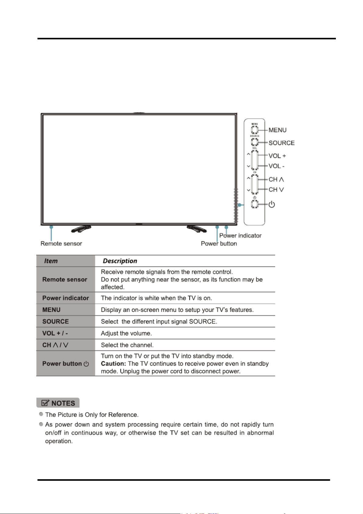
2.2 TV Front and Rear
TV Front
LTDN85XT910XWAM3D
- 10 -
Page 11
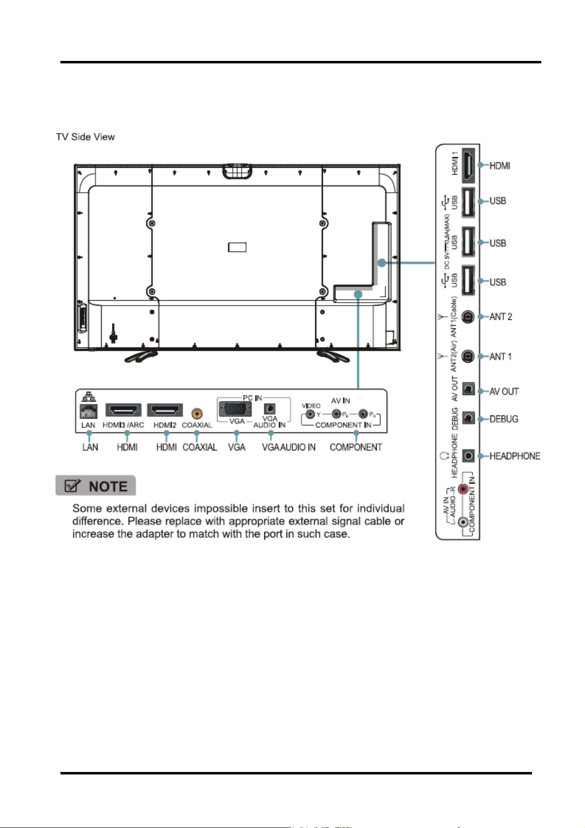
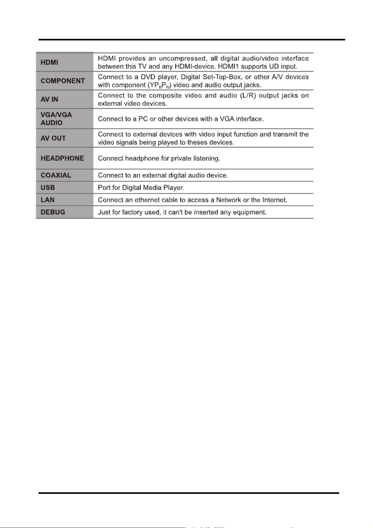
TV Back connections
LTDN85XT910XWAM3D
- 11 -
Page 12
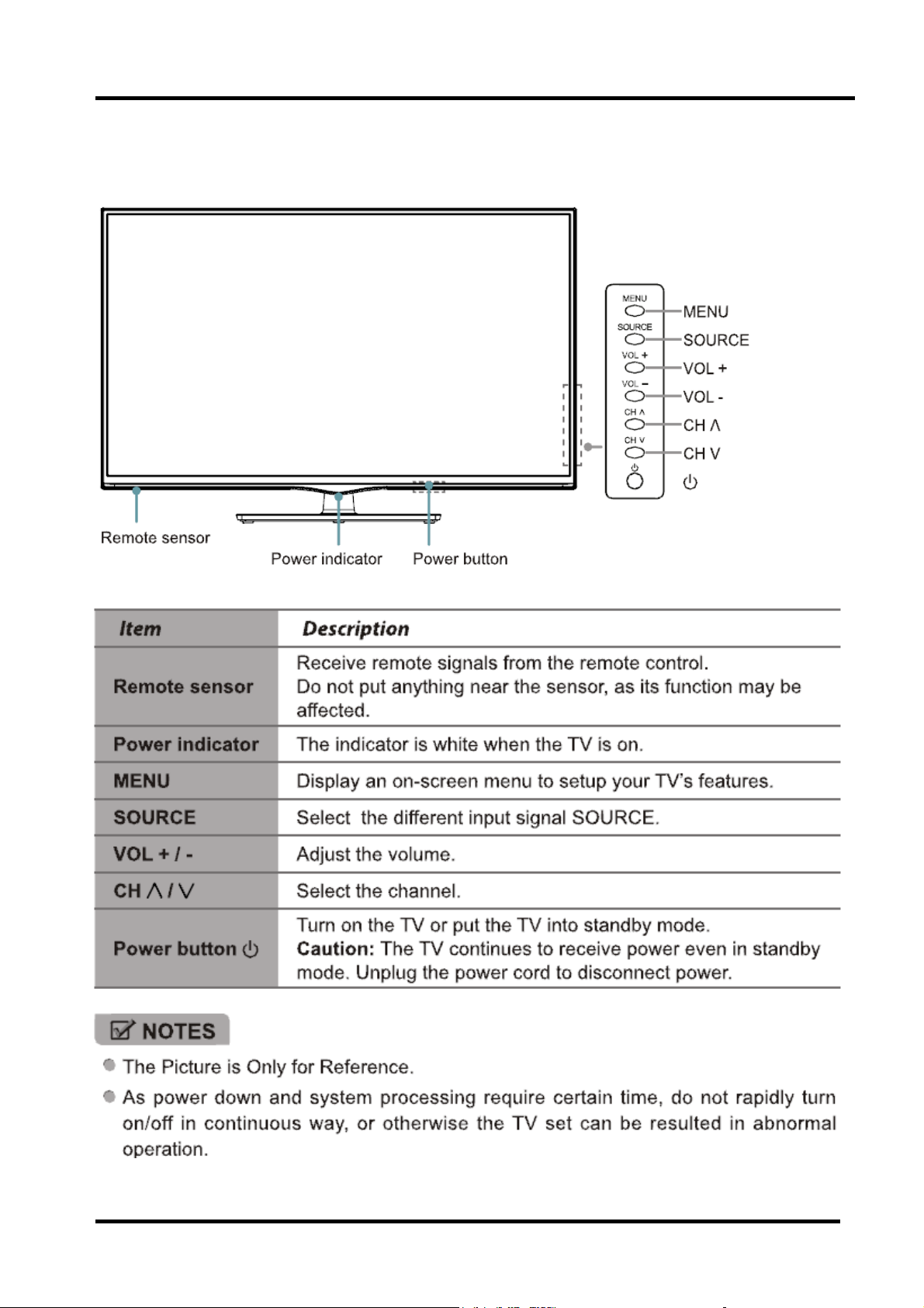
TV Front
LTDN55K680XWAM3D
- 12 -
Page 13
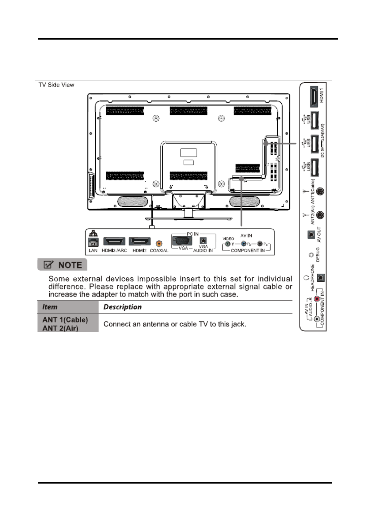
TV Back connections
LTDN55K680XWAM3D
- 13 -
Page 14
- 14 -
Page 15
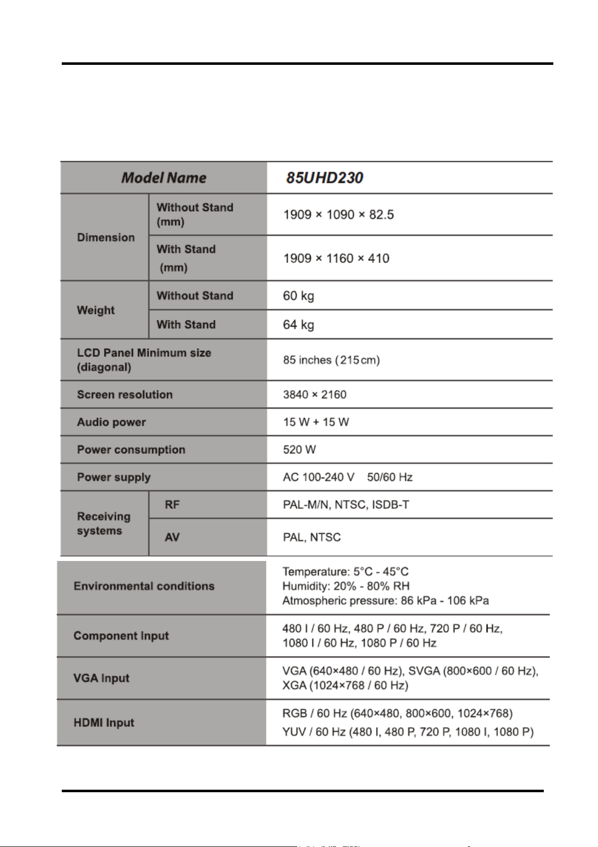
2.3 Specification
LTDN85XT910XWAM3D ---Spec.
- 15 -
Page 16

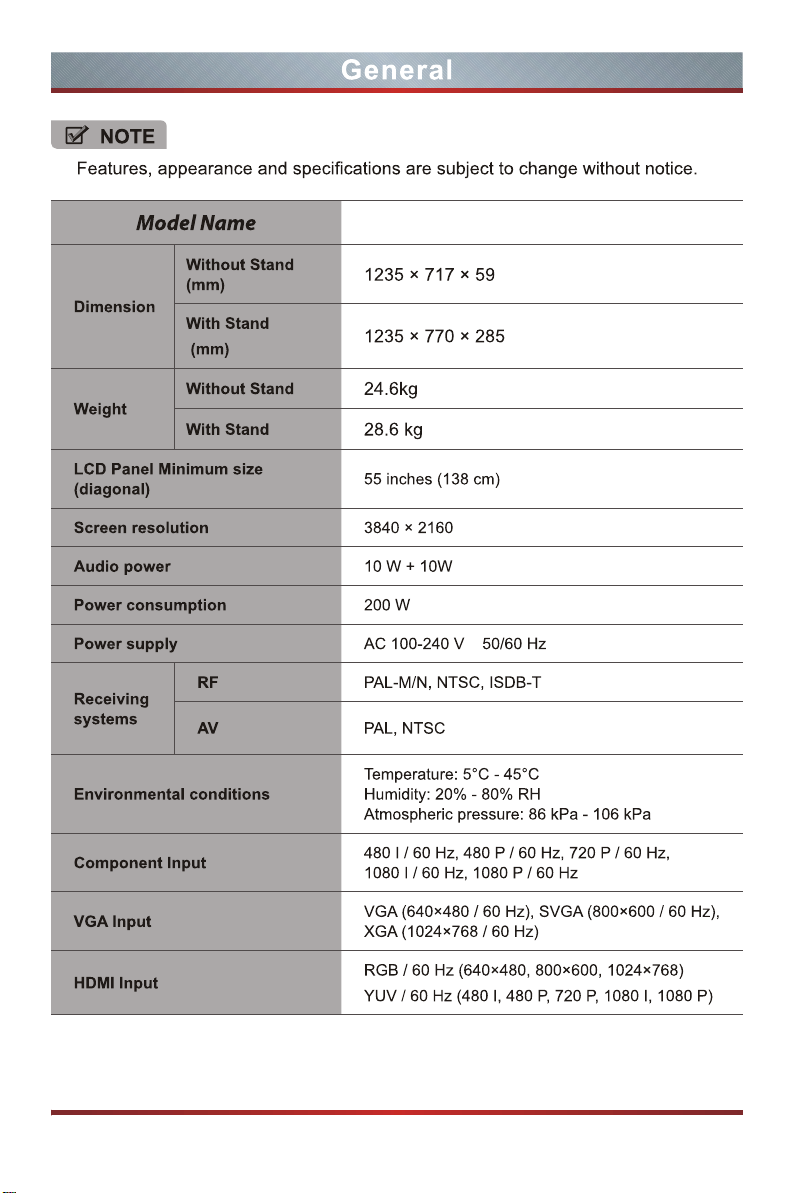
LTDN55K680XWAM3D--- Spec.
- 16 -
Page 17
LTDN55K680XWAM3D(20)
Page 18
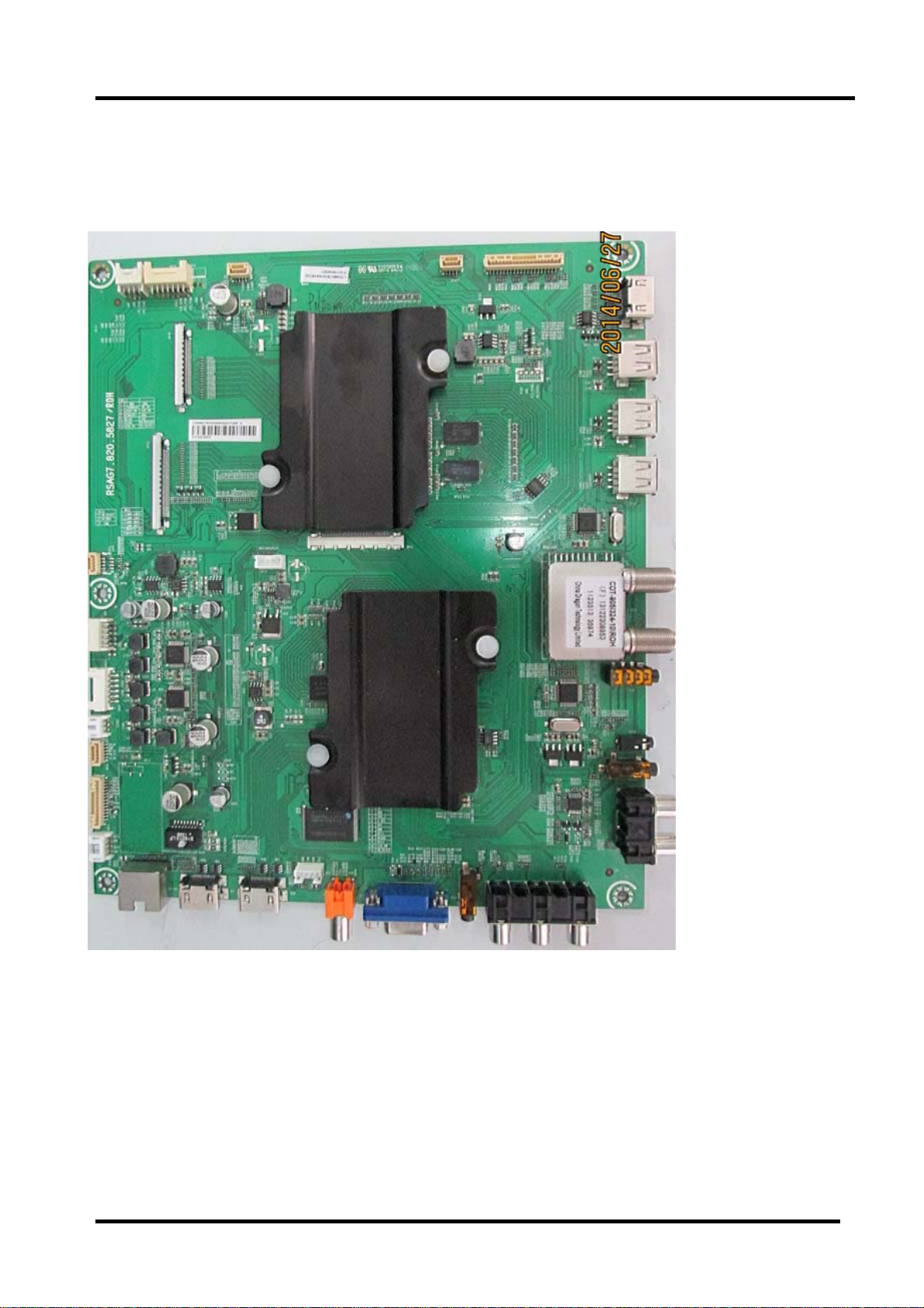
2.4 Main board layout
Main board: 5827 TOP:
Detail description look up the quick setup guide, please.
- 17 -
Page 19
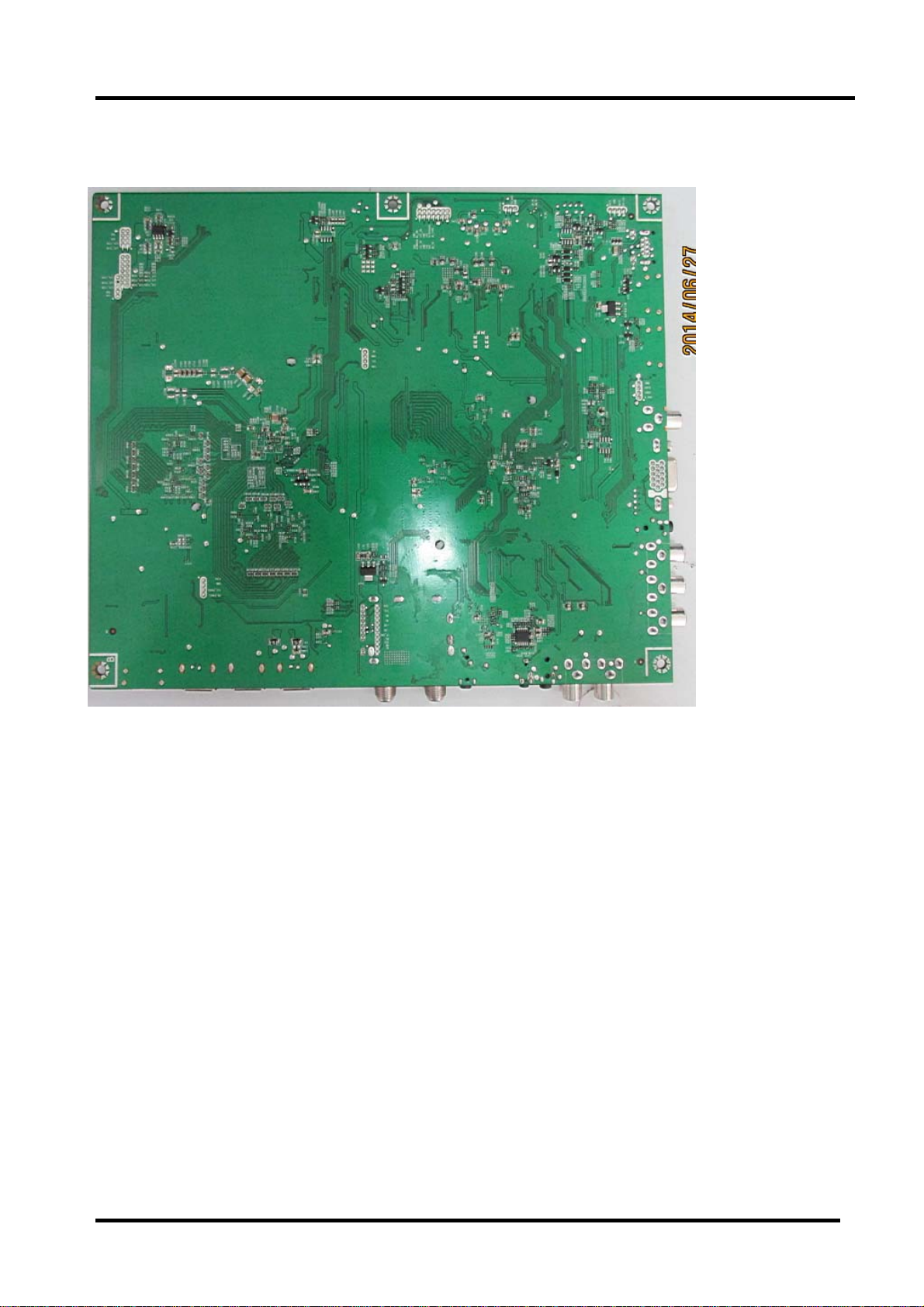
Bottom:
- 18 -
Page 20
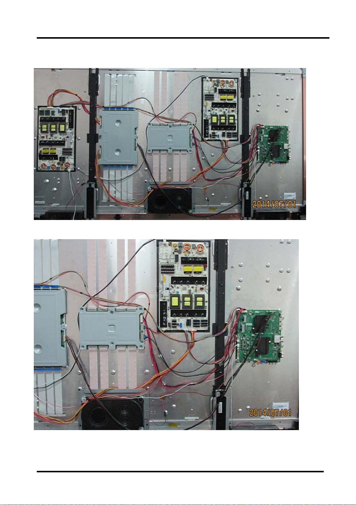
2.5 LTDN85XT910XWAM3D assemble figure
(Firgure-1)
(Firgure-2)
- 19 -
Page 21
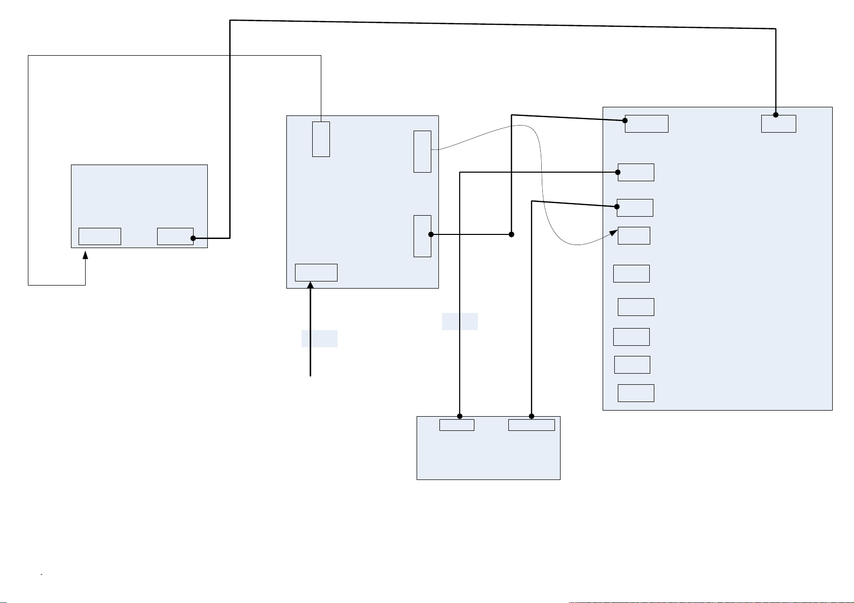
LTDN55K680XWAM3D
(1)
XP706
Inverter:
XP703
(2)
XP802
Power board : 5567
XP801
Power in
(3)
XP19
XP803 XP806
(4)
XP18
XP35
(5)
XP2
XP32
MB: 5827
XP23
XP10
(8)
(9)
(6)
(7)
XP34
XP17
XP20
(10)
(11)
(12)
TCON
Page 22
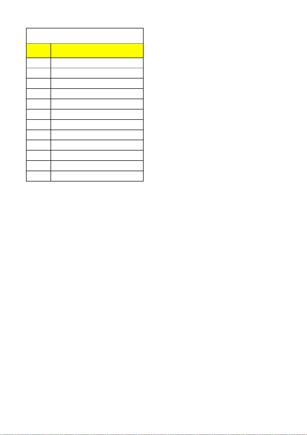
LTDN55K680XWAM3D
No. Connector
1 Inverter XP706---PB: XP802
2 Inverter XP703---MB: XP32
3 Power in
4 PB: XP803--MB:XP2
5 PB XP806--MB:XP19
6 MB: XP18---TCON
7 MB: XP35---TCON
8 MB:XP23 Speaker
9 MB:XP10 3D
10 MB:XP34 WIFI
11 MB:XP17 LED
12 MB:XP20 keypad
Page 23

3. Factory/Service OSD Menu and Adjustment
3.1 To enter the Factory OSD Menu
With user’s RC
1. Power TV On
2. Press Menu button and call up User OSD Menu
3. Select Audio-> Balance, when Balance is “0”
4. Enter 1->9->6->9 in sequence.
Note: If necessary, re-enter number keys.
5. Factory OSD appears.
6. Press "EXIT" Key on remote control then can leave factory OSD Menu.
3.2 Factory OSD Menu
Take LTDN50K660RWAM3D for example
- 20 -
Page 24

3.2.1 White Balance
Note: Different source has different WB values. Before adjusting, please change to desired source.
3.2.2 Signal prefabricate
- 21 -
Page 25

3.2.3 Factory Option
Item Default Options Notes
M-Can enter factory mode with factory
1 MODE M M, U
Note: MODE “M” is only used for factory production.
Item Default Options Note
1
2
Note: Software version info of the TV, readable only.
Item Meaning Note
Clean Protected Clear partly
Clean All Clear completely
Version
Date
U-Can enter factory mode only with
Software version
The date of current version
RC or user RC.
user’s RC.
- 22 -
Page 26

Note: The factory menu date varies according to different sources. Incase changing the factory
data by error, you can choose to “Clean ALL”, by which you can resume the default value.
To clear the EEPROM:
a. Select the item “Clean All”.
b. Press VOL+ button to clear the EEPROM data.
c. Close the OSD menu after 5 seconds.
d. Restart the TV.
3.3 Designer Menu
- 23 -
Page 27

Note:
The above “Factory/Service OSD Menu”is reference for chassis MTK5652 , please refer to
the actual units to determine the appearances for different TV.
- 24 -
Page 28

4. Software Upgrading
4.1 USB Software Upgrading directly
The software can be upgraded by USB Disk.
First, copy the upgrade_loader.pkg file to USB Disk;.
Second, make sure there is no other .pkg file in the root directory of USB Disk.
Insert USB Disk to USB port, and then power on the TV.
The TV will identify the software and upgrade automatically.
4.2 USB upgrading unsuccessfully
If USB upgrading unsuccessfully, then need burning the Nand Flash program
file“ *.bin ”to the Nand Flash.
Hardware connecting
Connect the unit to your pc with a USB-to-serial port cable. USB port connects to your PC and
serial port to the TV’s RS232 port. As following
Connect to
the TV RS232
port
USB Connect to
the PC
- 25 -
Page 29

4.2.1 Install the driver
Double click the icon , install the driver.
Select the default value, the driver will be installed step by step.
- 26 -
Page 30

- 27 -
Page 31

4.3 Upgrading with the FlashTool0.6.0.exe
1、FlashTool is a green program needing no installation. After Connect the unit to
your pc with a USB-to-serial port cable,run FlashTool0.6.0.exe.
following steps to set.
.
Select mode
of main chip
serial port
Communicate port
Please refer to the
Set Flash Baud Rate
How to choose
instruction..
Communicate port and flash baud rate? See the following
- 28 -
Page 32

Open “Device Manager” and find which port is connected with the TV. In above picture, COM4
is connected to the TV, so, select “COM4” and if COM6 is connected to the TV, so select “COM6”.
Select the right baud rate according to chip model. For this unit( chip model is MT5652), select 115200.
2、 Click to connect,if connect successfully then button from red turn
green
.
- 29 -
Page 33

Click , bounce the following dialog box. Load Bin File:find the upgrading
programfile,andselectit.forexample:HIS_5651_m1v2_oceania_secure_nandboot.bin.
Press“Upgrade”buttonandstartupgrading.,ifupdatedefeat,tryagain.
Start upgrade
Select *.bin file
If bootloader Tool upgrading is ok, then need renew USB upgrading.reference to 4.1( USB
Software Upgrading directly)
- 30 -
Page 34

4.4 Network updating
Network updating includes three ways. Auto Upgrade 、Network upgrade and USB upgrade.
No matter Auto Upgrade is ON or Off,Network Upgrade is validated
4.4.1 Auto Upgrade---- When set to “on” , system can automatically check whether or not have any new
updating file in servers after have connected to the network. Customer can download and
update according to the guide.
Network upgrade ---- Check the process and it will prompt you to upgrade the software.
Network upgrade
Press “menu” key with RC, select as following.
Figure-1
- 31 -
Page 35

Figure-2
Check new version, bounce the following.
Select Yes to downloading……
Figure-3
Figure-4
- 32 -
Page 36

After verify, bounce dialog to select “yes” to update the firmware. Waiting……
Figure-5
Figure-6
- 33 -
Page 37

Figure-7
- 34 -
Page 38

Bounding the following interface that indicates firmware update is successful.
Figure-8
Remote control Power off and restart TV. indication led is linking .about 5 minutes , TV bounce
following prompt message. otherwise upgrade is defeated.
Figure-9
- 35 -
Page 39

USB upgrade:
1. Copy the upgrade_loader.pkg file to USB Disk;.
2. Make sure there is no other .pkg file in the root directory of USB Disk.
3. Insert USB Disk to USB port. and then turn on the TV.
Next update steps can according to the network upgrade.
figure-2
- 36 -
Page 40

5. Trouble shooting
When there is something wrong with your TV, you can try turning off the TV and then restart it.
You can also operate according to the follow chart. If the problems still cann’t be solved, please
contact the profession technician.
- 37 -
Page 41

5.1 Troubleshooting for Remote Control
Remote control does not work
Try new batteries
NO
Replace RC
Check IR receiver
YES
YES
Replace battery
Replace remote control
Change Led & IR board
NO
Change Led & IR cable
NO
Replace main board
YES
Replace Led & IR BD
YES
Replace Led & IR cable
- 38 -
Page 42

5.2 Troubleshooting for Function Key
Buttons does not work
Check switches
YES
Check solder connections and
see if any switches are stuck.
NO
Check key board
NO
Check Key BD cable
YES
Replace Key BD
YES
Change Key BD
OK
NO
Replace main board
- 39 -
Page 43

5.3 TV won’t Power On
TV won’t power on
Is LED
light?
NO
Check Power
Output
YES
Make Sure Power
source is live
YES
NO
BLUE
RED
Panel Bright
NO
YES
Check signal
Source
YES
NO
Check Power
Cord
NO
Try Power on by
RC and Button
Neither
works
Replace Main
BD
YES
Only
one works
Both
Work
Replace
Power Cord
Check/replace IR
BD or Keypad
PCA
NO
(to contact HITACHItech support.)
Replace Main BD
Replace Panel
OK
YES
Power on
NO
Replace Power BD
YES
OK
Note:
Above the indicated led color is only for standby is red , normal is blue.
- 40 -
Page 44

5.4 Troubleshooting for Audio
No sound
Check connecter
YES
Reconnect
NO
Check speaker wire
NO
Check speaker set
YES
YES
Replace speaker wire
Replace speaker set
NO
Replace main board
NO
YES
OK
Power Supply Board
- 41 -
Page 45

5.5 Troubleshooting for TV/VGA/HDMI input
No picture on the screen
NO
Check Signal Source
Make sure signal
source is available
YES
Check connect
NO
YES
Check cab l e
NO
Replace main board
Reconnect
Replace cable
- 42 -
Page 46

5.6 Troubleshooting for YPbPr input
No picture on the screen
Check Source work or not
YES
Check connect
NO
Check Wires (Green Blue, Red)
NO
Replace main board
NO
YES
YES
Check Source Device
Reconnect
Replace wires
- 43 -
Page 47

5.7 Troubleshooting for Video input
No picture on the screen
Check Source work or not
YES
Check connect
NO
Check Cable/ Wires
NO
Replace main board
NO
YES
YES
Check Signal Source
Reconnect
Replace Cable/Wires
- 44 -
Page 48

6. Signals Block Diagram and power assign:
(The next page)
7. Schematic circuit diagram
8. Explode View
- 45 -
Page 49

V-By-1(0~7)
CSOT Panel
Speater_L
Speater_R
内置低音
RF IN
Ethernet
DDR3
2G+2G+2G+2G/64bit
SPI Flash
?
32M bit
AMP_1
TAS5707
AMP_2
TAS5711
EEPROM
32k Byte
DDR3
2G+2G
eMMC Flash(OPTION)
4G/Byte
SPI Flash(OPTION)
16M bit
TUNER
XUGUANG
PM44-11BP
MST6M40A
I2C1
I2C0 LVDS OUT
I2S
MT5652
I2C_TUNER
IP/IM
Ethernet
V-By-1(8~15)
LVDS(2ch)
LVDS(2ch)
HDMI IN
HDMI OUT
LVDS IN
HDMI3
HDMI2
HDMI1
AV
YPbPr
VGA
EarPhone
SPDIF
USB0
USB1
USB Hub
USB2514
LG Panel
AUO Panel
CMI Panel
HDMI SWITCH
Sil9687
AV1
YPbPr
VGA
EarPhone
SPDIF
WiFi
USB1
USB2
HDMI1
HDMI2
HDMI3/CEC
HDMI4/ARC
IR
JATG
UART
USB3
Page 50

A
MT5652
GPIO LIST
PIN NAME
GPIO_0
GPIO_1
GPIO_2
GPIO_3
GPIO_4
GPIO_5
GPIO_6
GPIO_7
GPIO_8
GPIO_9
GPIO_10
GPIO_11
ADIN0
ADIN1
ADIN2
ADIN3
ADIN4
ADIN5
OPCTRL0
OPCTRL1
OPCTRL2
OPCTRL3
OPCTRL4
OPWM0
A A
OPWM1
OPWM2
OPWM3
OPWM4
OPWM5
OPWM6
PACLE
CIGPIO0
GPIO Function
Function define
LOCAL_DIM_EN
TUNER_SW
LVDS_PWR_EN
EMMC_RST
Demod_RST#
not used
3D_EN
3D相关
3D相关
3D_OUT
HPDET#
SYS_EEPROM_WP
SCART_FS_SEL
通过10k接 地,未 使用
ADIN0
ADIN1
LED_DX
POWER_LED
FLASH写保护控制
BL_ON/OFF
AMP_MUTE
strap[2]
strap[3] RST_AMP
WIFI_EN
MEMC_ON/OFF
BL_DIMMING
MUTE_HP
3D_CTRL
LED2/PHYAD2
LED3/PHYAD3
strap[0]
RESERVED LVDS预留
NAND
Flash
Serial
Flash
DRAM
IR
JTAG
UART
NAND INTERFACE
SPI
Block Diagram
LVDS
LVDS Port
Main Chip
MT5652
USB2
HDMI1
HDMI0
HDMI2
USB0
USB1
RGB
Eth
Embedded
Eth PHY
SPDIF OUT SPDIF OUT
SPEAKER AMP
HPOUT
SPEAKER OUT
Headphone Out
Tuner IF+/IF-
TS STREAM
SC
DEMO
YPbPr1
LINE IN
CVBS
AV_OUT
LINE OUT
TUNER
CIGPIO15
CIGPIO16
CIGPIO17
CIGPIO18
CIGPIO19
CIGPIO20
CIGPIO21
CIGPIO22
CIGPIO23
CIGPIO24
CIGPIO25
TS1_OUT_CLK
TS1_OUT_VLD
TS1_OUT_SYNC
TS1_OUT_D0
TS1_OUT_D1
TS1_OUT_D2
TS1_OUT_D3
TS1_OUT_D4
TS1_OUT_D5
TS1_OUT_D6
TS1_OUT_D7
USBx3 HDMIx3
A
VGA
YPbPr1
AV IN
AV OUT
Hisense Electric Co.,LTD
Hisense Electric Co.,LTD
Hisense Electric Co.,LTD
Title
Title
Title
INDEX
INDEX
INDEX
Size Docum ent Number Rev
Size Docum ent Number Rev
Size Docum ent Number Rev
MT5652
MT5652
MT5652
A2
A2
A2
Date: Sheet of1 17
Friday, October 18, 2013
Date: Sheet of1 17
Friday, October 18, 2013
Date: Sheet of1 17
Friday, October 18, 2013
1.0
1.0
1.0
Page 51

LVDS IN & VB1 OUT
MB:5827
N45B MST6M40
AG9
RA0N
AH9
RA0P
AJ10
RA1N
AJ9
RA1P
AJ11
RA2N
AH10
RA2P
AH11
RACKN
AG10
RACKP
AG11
RA3N
AG12
RA3P
AJ12
RA4N
AH12
RA4P
AM4
T2A_N
RB0N
AL4
T2A_P
RB0P
AK4
T2B_N
RB1N
AL5
T2B_P
RB1P
AK5
T2C_N
RB2N
AL6
T2C_P
RB2P
AM6
T2CK_N
RBCKN
AK6
T2CK_P
RBCKP
AM7
T2D_N
RB3N
AL7
T2D_P
RB3P
AK7
T2E_N
RB4N
AL8
T2E_P
RB4P
AK8
T3A_N
RC0N
AL9
T3A_P
RC0P
AM9
T3B_N
RC1N
AK9
T3B_P
RC1P
AM10
T3C_N
RC2N
AL10
T3C_P
RC2P
AK10
T3CK_N
RCCKN
AL11
T3CK_P
RCCKP
AK11
T3D_N
RC3N
AL12
T3D_P
RC3P
AM12
T3E_N
RC4N
AK12
T3E_P
RC4P
AM13
RD0N
AL13
RD0P
AK13
RD1N
AL14
RD1P
AK14
RD2N
AL15
RD2P
AM15
RDCKN
AK15
RDCKP
AM16
RD3N
AL16
RD3P
AK16
RD4N
AL17
RD4P
AK17
RE0N
AL18
RE0P
AM18
RE1N
AK18
RE1P
AM19
RE2N
AL19
RE2P
AK19
RECKN
AL20
RECKP
AK20
RE3N
AL21
RE3P
AM21
RE4N
AK21
RE4P
AM22
RXM[0]
AL22
RXP[0]
AK22
RXM[1]
AL23
RXP[1]
AK23
RXM[2]
AL24
RXP[2]
AM24
RXM[3]
AK24
RXP[3]
AM25
RXM[4]
AL25
RXP[4]
AK25
RXM[5]
AL26
RXP[5]
AK26
RXM[6]
AL27
RXP[6]
AM27
RXM[7]
AK27
RXP[7]
AM28
RXM[8]
AL28
RXP[8]
AK28
RXM[9]
AL29
RXP[9]
AK29
RXM[10]
AL30
RXP[10]
AM30
RXM[11]
AK30
RXP[11]
AD28
VX1R_HTPD_O / GPIO[12]
AD29
VX1R_HTPD_V / GPIO[13]
AC27
VX1R_HTPD_V2 / GPIO[14]
AC28
VX1R_LOCK_O / GPIO[15]
AB27
VX1R_LOCK_V / GPIO[16]
AB28
VX1R_LOCK_V2 / GPIO[17]
LVDS in VX1RX
LVDS & VB1 out
A0P / MLVB4_0P / VBY0N
A0M / MLVB4_0N / VBY0P
A1P / MLVB4_1P / VBY1N
A1M / MLVB4_1N / VBY1P
A2P / MLVB4_2P / VBY2N
A2M / MLVB4_2N / VBY2P
ACKP / MLVB4_CKP / VBY3N
ACKM / MLVB4_CKN / VBY3P
A3P / MLVB4_3P / VBY4N
A3M / MLVB4_3N / VBY4P
A4P / MLVB4_4P/ VBY5N
A4M / MLVB4_4N / VBY5P
B0P / MLVB4_5P / VBY6N
B0M / MLVB4_5N / VBY6P
B1P / MLVB3_0P / VBY7N
B1M / MLVB3_0N / VBY7P
MOD_GPIO0 / MLVB3_1P
MOD_GPIO1 / MLVB3_1N
B2P / MLVB3_2P
B2M / MLVB3_2N
BCKP / MLVB3_CKP
BCKM / MLVB3_CKN
B3P / MLVB3_3P
B3M / MLVB3_3N
B4P / MLVB3_4P
B4M / MLVB3_4N
C0P / MLVB3_5P
C0M / MLVB3_5N
C1P / MLVB2_0P
C1M / MLVB2_0N
C2P / MLVB2_1P
C2M / MLVB2_1N
CCKP / MLVB2_2P
CCKM / MLVB2_2N
C3P / MLVB2_CKP
C3M / MLVB2_CKN
C4P / MLVB2_3P
C4M / MLVB2_3N
D0P / MLVB2_4P
D0M / MLVB2_4N
D1P / MLVB2_5P
D1M / MLVB2_5N
MOD_GPIO2 / MLVB1_0P
MOD_GPIO3 / MLVB1_0N
D2P / MLVB1_1P
D2M / MLVB1_1N
DCKP / MLVB1_2P
DCKM / MLVB1_2N
D3P / MLVB1_CKP
D3M / MLVB1_CKN
D4P / MLVB1_3P
D4M / MLVB1_3N
MOD_GPIO4 / MLVB1_4P
MOD_GPIO5 / MLVB1_4N
MOD_GPIO6 / MLVB1_5P
MOD_GPIO7 / MLVB1_5N
E0P / MLVF4_0P / VBY8N
E0M / MLVF4_0N / VBY8P
E1P / MLVF4_1P / VBY9N
E1M / MLVF4_1N / VBY9P
E2P / MLVF4_2P / VBY10N
E2M / MLVF4_2N / VBY10P
ECKP / MLVF4_CKP / VBY11N
ECKM / MLVF4_CKN / VBY11P
E3P / MLVF4_3P / VBY12N
E3M / MLVF4_3N / VBY12P
E4P / MLVF4_4P/ VBY13N
E4M / MLVF4_4N / VBY13P
F0P / MLVF4_5P / VBY14N
F0M / MLVF4_5N / VBY14P
F1P / MLVF3_0P / VBY15N
F1M / MLVF3_0N / VBY15P
MOD_GPIO8 / MLVF3_1P
MOD_GPIO9 / MLVF3_1N
F2P / MLVF3_2P
F2M / MLVF3_2N
FCKP / MLVF3_CKP
FCKM / MLVF3_CKN
F3P / MLVF3_3P
F3M / MLVF3_3N
F4P / MLVF3_4P
F4M / MLVF3_4N
G0P / MLVF3_5P
G0M / MLVF3_5N
G1P / MLVF2_0P
G1M / MLVF2_0N
G2P / MLVF2_1P
G2M / MLVF2_1N
GCKP / MLVF2_2P
GCKM / MLVF2_2N
G3P / MLVF2_CKP
G3M / MLVF2_CKN
G4P / MLVF2_3P
G4M / MLVF2_3N
H0P / MLVF2_4P
H0M / MLVF2_4N
H1P / MLVF2_5P
H1M / MLVF2_5N
MOD_GPIO10 / MLVF1_0P
MOD_GPIO11 / MLVF1_0N
H2P / MLVF1_1P
H2M / MLVF1_1N
HCKP / MLVF1_2P
HCKM / MLVF1_2N
H3P / MLVF1_CKP
H3M / MLVF1_CKN
H4P / MLVF1_3P
H4M / MLVF1_3N
MOD_GPIO12 / MLVF1_4P
MOD_GPIO13 / MLVF1_4N
MOD_GPIO14 / MLVF1_5P
MOD_GPIO15 / MLVF1_5N
TX_AO0NH
T2A_N
I2C-SDA-L
RP220R
TX_AO0PH
T2A_P
TX_AO1NH
T2B_N
TX_AO1PH
T2B_P
TX_AO2NH
T2C_N
RP250R
TX_AO2PH
T2C_P
TX_AOCKNH
T2CK_N
TX_AOCKPH
T2CK_P
TX_AO3NH
T2D_N
RP310R
TX_AO3PH
T2D_P
TX_AO4NH
T2E_N
TX_AO4PH
T2E_P
TX_AE0NH
T3A_N
RP1550R
TX_AE0PH
T3A_P
TX_AE1NH
T3B_N
TX_AE1PH
T3B_P
TX_AE2NH
T3C_N
RP1540R
TX_AE2PH
T3C_P
TX_AECKNH
T3CK_N
TX_AECKPH
T3CK_P
TX_AE3NH
T3D_N
RP340R
TX_AE3PH
T3D_P
TX_AE4NH
T3E_N
TX_AE4PH
T3E_P
GND
GND
+3.3V_6M40
+3.3V_6M4017,19,20
GPIO07
GPIO074,13
+12V
+12V12,13,16,17
1
SPI_CZ
R588
10R
2
SPI_DO
R541
10R
R589 10k
R1027 1k/NC
4
R1061
R1060
+3.3V_6M40
UART2_TX
R594
10k/NC
100R/NC
OSCL0
OSCL0 8,12,14
OSDA0
OSDA0 8,12,14
100R/NC
预留给 裸眼3D用 。
+12V
BLM18PG121SN1
L9
C1009
C725
C1010
R959
10u/16V
100n/16V
20k
C726
100n/16V
IO
口?
ON_SWITCH PANEL
ON_SWITCH PANEL
ON_SWITCH PANEL
LOW: OFF
HIGH:ON
VCC-Switch Panel
R961
20k
R963
0R
R962
4.7k
R964
IO
0R
XP31
61
60
59
58
57
56
54
55
21
22
XP32
local
dimming的pin
3D_EN ----- ----DIM4(GPIO3 6) ball AG21
SW_RESET ----D IM5(GPIO37) ba ll AG22
SCAN_EN --- -DIM6(GPIO38) ball AH22
LOCAL_EN ---- -DIM7(GPIO39) ball AG23
VSYNC_IN --- - VSYNC_Like b all AD27
SERIAL_STT --- -PWM0/SPI2_CK ball AF28
SERIAL_DATA - -----SPI4_DI b all AG28
SERIAL_CLK ------SPI4_CK ball AG27
1u/16V/NC
V64
3
R957
1
4.7k
2
ON_SWITCH PANEL
VCC-Switch Panel
PIN1
PIN1IO
1
2
OSCL0
R966
33R
3
OSDA0
R967
33R
4
5
6
7
8
9
10
11
12
T2A_N
13
T2A_P
14
T2B_N
15
T2B_P
16
T2C_N
17
T2C_P
18
19
T2CK_N
20
T2CK_P
21
22
T2D_N
23
T2D_P
24
T2E_N
25
T2E_P
26
27
28
T3A_N
29
T3A_P
30
T3B_N
31
T3B_P
32
T3C_N
33
T3C_P
34
35
T3CK_N
36
T3CK_P
37
38
T3D_N
39
T3D_P
40
T3E_N
41
T3E_P
42
43
44
45
46
47
48
49
50
51
52
53
20
19
18
17
16
15
14
13
12
11
10
9
8
7
6
5
4
3
2
1
VCC-Panel
R845 100R
R968 100R/NC
R802 100R
R859 100R
R1059 0R
R810 100R
R848 100R
R847 100R
R852 100R
R857 100R
TEST_MODE
3D_EN
SCAN_DEMO_EN
SCAN_EN
LD_EN1
VSYNC_IN
SERIAL_STT
SERIAL_DATA
SERIAL_CLK
R858 100R
调试用
3D_EN1
I2C-SCL-L
LOCAL- DIMMING
脚连接关系,请 参考如下表格:
三星75寸 背光控制
V51
R958
4.7k
MMBT3904LT1
PIN1
OSCL0 2,9,12
OSDA0 2,9,12
+3.3V_6M40
R969
4.7k
I2C-SDA-L
VCC-Switch Panel
312
AO3401L
C727
10u/16V
XP1
R960
4
3
0R
2
1
XP1
的封装?
R970
R971
R972
4.7k
4.7k
4.7k
+3.3V_6M40
R482
R973
4.7k
4.7k
ADD BYdiaochunnuan
R974
4.7k
100n/16V
C728
R488
4.7k
TX_AO0NH
2
TX_AO0PH2
TX_AO1NH2
2
TX_AO1PH
TX_AO2NH2
TX_AO2PH
2
TX_AOCKNH2
10R
10R
R601
R602
1
R796 100R
1
R795 100R
R603
R604
R1022
R1037
TX_AOCKPH2
TX_AO3NH
2
TX_AO3PH2
TX_AO4NH2
TX_AO4PH2
TX_AE0NH
2
TX_AE0PH2
TX_AE1NH2
2
TX_AE1PH
TX_AE2NH2
TX_AE2PH
2
TX_AECKNH2
TX_AECKPH2
TX_AE3NH
2
TX_AE3PH
2
TX_AE4NH2
TX_AE4PH2
3,4,5,6,7,8,9,10,11,12,13,14,15,16,17
MX25L1605D-SST25VF016B
VCC8CS#
7
SO/SIO1
LOLD#
6
WP#/ACC3SCLK
5
GND
SI/SIO0
N2
22R
6M40_SCL
22R
6M40_SDA
I2CM_SCL
I2CM_SDA
22R
6M40_UART1_RX18
22R
6M40_UART1_TX18
UART2_RX
33R
UART2_TX
33R
I2C-SCL-L
HDMI
AL2
VBY0N_TX
VBY0N_TX 20
AL1
VBY0P_TX
VBY0P_TX 20
AK3
VBY1N_TX
VBY1N_TX 20
AK1
VBY1P_TX
VBY1P_TX 20
AJ3
VBY2N_TX
VBY2N_TX 20
AJ2
VBY2P_TX
VBY2P_TX 20
AH3
VBY3N_TX
VBY3N_TX 20
AH2
VBY3P_TX
VBY3P_TX 20
AG3
VBY4N_TX
VBY4N_TX 20
AG1
VBY4P_TX
VBY4P_TX 20
AG2
VBY5N_TX
VBY5N_TX 20
AF3
VBY5P_TX
VBY5P_TX 20
AE3
VBY6N_TX
VBY6N_TX 20
AE2
VBY6P_TX
VBY6P_TX 20
AE1
VBY7N_TX
VBY7N_TX 20
AD3
VBY7P_TX
VBY7P_TX 20
AD2
AC3
AA5
Y4
AC2
AB3
Y5
Y6
AB2
AB1
W6
V6
AA3
AA1
W5
W4
AA2
Y3
V5
U4
Y2
W3
U5
U6
W2
W1
T6
R6
V3
V1
T5
T4
V2
U3
R5
P4
U2
T3
P5
P6
T1
VBY8N_TX
VBY8N_TX 20
R3
VBY8P_TX
VBY8P_TX 20
R1
VBY9N_TX
VBY9N_TX 20
R2
VBY9P_TX
VBY9P_TX 20
P2
VBY10N_TX
VBY10N_TX 20
N3
VBY10P_TX
VBY10P_TX 20
N2
VBY11N_TX
VBY11N_TX 20
N1
VBY11P_TX
VBY11P_TX 20
M1
VBY12N_TX
VBY12N_TX 20
M2
VBY12P_TX
VBY12P_TX 20
L3
VBY13N_TX
VBY13N_TX 20
L2
VBY13P_TX
VBY13P_TX 20
K2
VBY14N_TX
VBY14N_TX 20
K1
VBY14P_TX
VBY14P_TX 20
J3
VBY15N_TX
VBY15N_TX 20
J1
VBY15P_TX
VBY15P_TX 20
H3
H2
G3
G2
G1
F3
F1
F2
E3
E2
D3
D2
G4
G5
H5
H6
G6
F4
D1
D4
C1
C2
B1
B2
A2
C3
A3
B3
C4
B4
C5
B5
A5
C6
A6
B6
C7
B7
C8
B8
VBY12N_TX
VBY12N_TX 14
VBY12P_TX
VBY12P_TX 14
VBY13N_TX
VBY13N_TX 14
VBY13P_TX
VBY13P_TX 14
VBY14N_TX
VBY14N_TX 14
VBY14P_TX
VBY14P_TX 14
VBY15N_TX
VBY15N_TX 14
VBY15P_TX
VBY15P_TX 14
N45E MST6M40
GPIO[8] / HDMIRX_CEC
GPIO[9] / HDMIRX_HPD
GPIO[6] / DDCDA_CK
GPIO[7] / DDCDA_DA
HDMI_RXCP
HDMI_RXCN
HDMI RX
HDMI_RX0P
HDMI_RX0N
HDMI_RX1P
HDMI_RX1N
HDMI_RX2P
HDMI_RX2N
GPIO[4] / HDMITX_CEC
GPIO[5] / HDMITX_HPD
HDMITX_SCL
HDMITX_SDA
HDMITX_CLKP
HDMITX_CLKN
HDMI TX
HDMI_TX0P
HDMI_TX0N
HDMI_TX1P
HDMI_TX1N
HDMI_TX2P
HDMI_TX2N
R616
C1030 20p/50V
12
0R
XTALO_S
R617
1M
XTALI_S
Z4
C1029 20p/50V
TP5
TP6
TP11
TP12
DIM0
DIM1
DIM2
OSCL08,9,12
OSDA08,9,12
R1021 10k
R540 10k
R1034 10k
1
1
1
1
Glass Sync From 6M40
R508 0R
R325 100R
R324 100R
U_RESET
XTALO_S
XTALI_S
6M40_SDA
6M40_SCL
I2CM_SDA
I2CM_SCL
UART2_TX
UART2_RX
6M40_UART1_TX
6M40_UART1_RX
SPI_CZ
SPI_CK
SPI_DI
SPI_DO
INT_R20
GPIO10
GPIO11
R1028 0R
HC-49SM24MHZ
+3.3V_6M40
AA28
AH23
AG24
AG25
AE31
AD30
AD32
AE32
AB29
AA29
AH25
AG26
AA26
AA27
6M40_SCL
6M40_SDA
AM3
AL3
AJ22
Debug/ISP ADDR
Slave (Debug Port:0xB4, ISP:0x98)
CHIP_CONF: {DIM2, DIM1, DIM0}
CHIP_CONF= 3'd7: 111 : boot from SPI Flash
GPIO & Debug
Glass Sync From 6M40
UD_HDMISCL_110
UD_HDMISDA_110
UD_HDMI_HPD1
10
AH28
R634 0R/NC
AH29
R628 0R/NC
AJ27
R1025 0R
AJ28
R1032 0R
AH32
R626 0R
AH31
R627 0R
AG32
R629 0R
AG30
R632 0R
AF30
R635 0R
AG31
R1036 0R
AE30
R1024 0R
AF31
R609 0R
AH26
AH27
AJ25
AJ26
AL31
AM31
AK31
AL32
AJ30
AK32
AH30
AJ31
N45C MST6M40
RESET
XTALO
XTALI
I2CS_SDA
I2CS_SCL
I2CM_SDA
I2CM_SCL / VSYNC_Like1
E8
GPIO[0](UART2_TX)
D8
GPIO[1](UART2_RX)
D9
GPIO[2](UART1_TX)
E9
GPIO[3](UART1_RX)
SPI_CZ
SPI_CK
SPI_DI
SPI_DO
INT_R21 / GPIO[41]
INT_R20 / GPIO[42]
GPIO[10] / PWM_DIM_IN[0]
GPIO[11] / PWM_DIM_IN[1]
F8
IRE
TESTPIN
GND_EFUSE
R1035 0R/NC
R620 0R
R580 0R/NC
R587 0R/NC
R1029 0R
R596 0R
R599 0R
R539 0R
R557 0R
R542 0R
R586 0R
R1030 0R
+3.3V_6M40
3
R614100k
1
R585 10k
22u/6.3V
C503
UD_HDMISCL_1
UD_HDMISDA_1
UD_RX1C
UD_RX1CB
UD_RX1_0
UD_RX1_0B
UD_RX1_1
UD_RX1_1B
UD_RX1_2
UD_RX1_2B
V55
BAV99LT1
R618 0R
2
UD_HDMISCL_1
UD_CEC1
HDMI_3_RX_C
HDMI_3_RX_CB
HDMI_3_RX_0
HDMI_3_RX_0B
HDMI_3_RX_1
HDMI_3_RX_1B
HDMI_3_RX_2
HDMI_3_RX_2B
C165
相对
1
R1026 0R
R1033 0R
R1023 0R
UD_CEC1 10
UD_HDMI_HPD1 3,10
UD_RX1C 2
UD_RX1CB 2
UD_RX1_0 2
UD_RX1_0B 2
UD_RX1_1 2
UD_RX1_1B 2
UD_RX1_2 2
UD_RX1_2B 2
HDMI_3_HPD
HDMI_3_SCL 3
HDMI_3_SDA 3
HDMI_3_RX_C 3
HDMI_3_RX_CB 3
HDMI_3_RX_0 3
HDMI_3_RX_0B 3
HDMI_3_RX_1
HDMI_3_RX_1B 3
HDMI_3_RX_2 3
HDMI_3_RX_2B 3
的值取决于电源系统的
+5V_Standby
的延迟时间。延迟上电越长,
C501 10u/10V
23
V49
MMBT3906LT1
R613 1k
R615
10k
I2C_HSC_SDA / VSYNC_Like2
I2C_HSC_SCL / VSYNC_Like3
SPI1_CK / PWM2 / GPIO58
SPI1_DI / PWM3 / GPIO59
SPI2_CK / PWM0 / GPIO56
SPI2_DI / PWM1 / GPIO57
SPI3_CK / DIM10 / GPIO54
SPI3_DI / DIM11 / GPIO55
SPI4_CK / DIM8 / GPIO52
SPI4_DI / DIM9 / GPIO53
VSYNC_Like / PWM5 / GPIO40
Local DimmingTCON
TCON8 / VX1T_HTPDN
TCON9 / VX1T_LOCKN
TCON10 / I2CM_SDA1
TCON11 / I2CM_SCL1
HDMI_3_SCL
HDMI_3_SDAUD_HDMISDA_1
3
+12V_Normal,+5V_Normal
t<10mS C165=2.2u
10mS<t<50mS C165=10u
t>50mS C165=100u
C504
100n/16V
DIM0 / GPIO[32]
DIM1 / GPIO[33]
DIM2 / GPIO[34]
DIM3 / GPIO[35]
DIM4 / GPIO[36]
DIM5 / GPIO[37]
DIM6 / GPIO[38]
DIM7 / GPIO[39]
STV2 / TCON0
OE / TCON1
YV1C / TCON2
CPV / TCON3
STV1 / TCON4
SFT / TCON5
TPV / TCON6
POL / TCON7
TCON12
TCON13
TCON14
TCON15
HDMI_3_SCL 3
HDMI_3_SDA 3
HDMI_3_HPD
C165
容值需越大。
U_RESET
AH24
1
TP8
AJ24
1
TP9
AE28
LR_SYNC_6M40
AE29
AF28
SERIAL_STT
AE27
AG29
3D_EN_6M40
AF27
R965
AG27
R1031 22R
SERIAL_CLK LD_EN_6M40
AG28
SERIAL_DATA
AD27
1
VSYNC_IN
AH20
DIM0
AG20
DIM1
AJ21
DIM2
AH21
ON_SWITCH PANEL
AG21
3D_EN1
AG22
SCAN_DEMO_EN
AH22
SCAN_EN
AG23
LD_EN1
E7
F7
D6
D5
E6
E5
F6
F5
AF4
VX1T_HTPDN
VX1T_HTPDN 20
AE4
VX1T_LOCKN
VX1T_LOCKN 20
AF5
AG4
AG5
AH4
3D_FLAG_U
R39 0R
AH5
AJ5
IO
33R/NC
TP10
ON_SWITCH PANEL
LR_SYNC_6M40
3D_EN_6M40 18
GPIO07
Glass Sync From Panel
LD_EN_6M40
TR30
TR7
T2A_N
TR8
T2A_P
TR9
T2B_N
TR10
T2B_P
TR11
T2C_N
T2C_P
TR12
TR13
T2CK_N
T2CK_P
TR14
TR15
T2D_N
TR16
T2D_P
TR17
T2E_N
T2E_P
TR18
TR19
T3A_N
TR20
T3A_P
TR21
T3B_N
TR22
T3B_P
TR23
T3C_N
T3C_P
TR24
TR25
T3CK_N
T3CK_P
TR26
TR27
T3D_N
TR28
T3D_P
TR29
T3E_N
T3E_P
Nor Flash
+3.3V_6M40
C10282.2u/10V
C1027
SPI_CK
R592
100n/16V
SPI_DI
R595
Debug Port
XP29
1
2
3
4
TP14
TP15
XP30
1
2
3
4
XP27
6
5
1
2
3
4
6
5
Page 52

C_DDR3_A15
MB:5827
C_DDR3_CSB1
C_DDR3_CSB2
AVDD_DDR0_S
C582
100n/16V
D_DDR3_DQ2
D_DDR3_DQ0
D_DDR3_DQ15
D_DDR3_DQ9
D_DDR3_DQ12
D_DDR3_DQ14
D_DDR3_DQ10
D_DDR3_DQ3
D_DDR3_DQ1
D_DDR3_DQ4
D_DDR3_DQ6
D_DDR3_DM1
D_DDR3_DQ11
D_DDR3_DQ8
D_DDR3_DM0
D_DDR3_DQ7
D_DDR3_DQ5
D_DDR3_DQS1
D_DDR3_DQS1B
D_DDR3_DQS0
D_DDR3_DQS0B
C596
C224
100n/16V
100n/16V
C_DDR3_A0
C_DDR3_A1
C_DDR3_A2
C_DDR3_A3
C_DDR3_A4
C_DDR3_A5
C_DDR3_A6
C_DDR3_A7
C_DDR3_A8
C_DDR3_A9
C_DDR3_A10
C_DDR3_A11
C_DDR3_A12
C_DDR3_A13
C_DDR3_A14
C_DDR3_BA0
C_DDR3_BA1
C_DDR3_BA2
C_DDR3_RASZ
C_DDR3_CASZ
C_DDR3_WEZ
C_DDR3_ODT
C_DDR3_CKE
C_DDR3_RESET
C_DDR3_MCLK
C_DDR3_MCLKZ
C_DDR3_DQ0
C_DDR3_DQ1
C_DDR3_DQ2
C_DDR3_DQ3
C_DDR3_DQ4
C_DDR3_DQ5
C_DDR3_DQ6
C_DDR3_DQ7
C_DDR3_DQ8
C_DDR3_DQ9
C_DDR3_DQ10
C_DDR3_DQ11
C_DDR3_DQ12
C_DDR3_DQ13
C_DDR3_DQ14
C_DDR3_DQ15
C_DDR3_DM0
C_DDR3_DM1
C_DDR3_DQS0
C_DDR3_DQS0B
C_DDR3_DQS1
C_DDR3_DQS1B
C_DDR3_DQ16
C_DDR3_DQ17
C_DDR3_DQ18
C_DDR3_DQ19
C_DDR3_DQ20
C_DDR3_DQ21
C_DDR3_DQ22
C_DDR3_DQ23
C_DDR3_DQ24
C_DDR3_DQ25
C_DDR3_DQ26
C_DDR3_DQ27
C_DDR3_DQ28
C_DDR3_DQ29
C_DDR3_DQ30
C_DDR3_DQ31
C_DDR3_DM2
C_DDR3_DM3
C_DDR3_DQS2
C_DDR3_DQS2B
C_DDR3_DQS3
C_DDR3_DQS3B
C220
C1041
100n/16V
100n/16V
AVDD_DDR0_S
RP100 22R
1 8
2
3
4 5
RP102 22R
1 8
2
3
4 5
RP105 22R
1 8
2
3
4 5
RP107 22R
1 8
2
3
4 5
RP97 22R
1 8
2
3
4 5
4 5
3
2
1 8
RP98 22R
4 5
3
2
1 8
RP99 22R
4 5
3
2
1 8
RP101 22R
4 5
3
2
1 8
RP103 22R
4 5
3
2
1 8
RP104 22R
4 5
3
2
1 8
RP106 22R
C586
100n/16V
C587
100n/16V
D15
B11
D14
D12
B12
D13
A12
E12
D17
C9
B13
D16
E16
A9
A11
E15
D11
E17
E11
E14
B10
C10
E10
C14
E13
C15
A14
D10
F10
D22
D18
D23
D19
B21
B15
A21
C16
B17
D21
E18
B20
D20
E21
E19
E20
C17
A20
B19
C19
A18
C18
C28
E22
B28
E23
A29
B22
B29
C23
D25
D27
E24
C27
D26
B26
E25
C26
D24
A27
C25
B24
C24
A23
7
6
7
6
7
6
7
6
7
6
6
7
6
7
6
7
6
7
6
7
6
7
C583
100n/16V
N45A
A_DDR3_A0
A_DDR3_A1
A_DDR3_A2
A_DDR3_A3
A_DDR3_A4
A_DDR3_A5
A_DDR3_A6
A_DDR3_A7
A_DDR3_A8
A_DDR3_A9
A_DDR3_A10
A_DDR3_A11
A_DDR3_A12
A_DDR3_A13
A_DDR3_A14
A_DDR3_A15
A_DDR3_BA0
A_DDR3_BA1
A_DDR3_BA2
A_DDR3_RASZ
A_DDR3_CASZ
A_DDR3_WEZ
A_DDR3_ODT
A_DDR3_CKE
A_DDR3_RESETB
A_DDR3_MCLK
A_DDR3_MCLKZ
A_DDR3_CSB1
A_DDR3_CSB2
A_DDR3_DQ0
A_DDR3_DQ1
A_DDR3_DQ2
A_DDR3_DQ3
A_DDR3_DQ4
A_DDR3_DQ5
A_DDR3_DQ6
A_DDR3_DQ7
A_DDR3_DQ8
A_DDR3_DQ9
A_DDR3_DQ10
A_DDR3_DQ11
A_DDR3_DQ12
A_DDR3_DQ13
A_DDR3_DQ14
MST6M40
A_DDR3_DQ15
A_DDR3_DM0
A_DDR3_DM1
A_DDR3_DQS0
A_DDR3_DQS0B
A_DDR3_DQS1
A_DDR3_DQS1B
A_DDR3_DQ16
A_DDR3_DQ17
A_DDR3_DQ18
A_DDR3_DQ19
A_DDR3_DQ20
A_DDR3_DQ21
A_DDR3_DQ22
A_DDR3_DQ23
A_DDR3_DQ24
A_DDR3_DQ25
A_DDR3_DQ26
A_DDR3_DQ27
A_DDR3_DQ28
A_DDR3_DQ29
A_DDR3_DQ30
A_DDR3_DQ31
A_DDR3_DM2
A_DDR3_DM3
A_DDR3_DQS2
A_DDR3_DQS2B
A_DDR3_DQS3
A_DDR3_DQS3B
D-DDR3-DQ2
D-DDR3-DQ0
D-DDR3-DQ13D_DDR3_DQ13
D-DDR3-DQ15
D-DDR3-DQ9
D-DDR3-DQ12
D-DDR3-DQ14
D-DDR3-DQ10
D-DDR3-DQ3
D-DDR3-DQ1
D-DDR3-DQ4
D-DDR3-DQ6
D-DDR3-DM1
D-DDR3-DQ11
D-DDR3-DQ8
D-DDR3-DM0
D-DDR3-DQ7
D-DDR3-DQ5
D-DDR3-DQS1
D-DDR3-DQS1B
D-DDR3-DQS0
D-DDR3-DQS0B
C585
C584
100n/16V
100n/16V
AVDD_DDR0_S
C597
100n/16V
C569
C570
C222
100n/16V
100n/16V
100n/16V
B_DDR3_A0
B_DDR3_A1
B_DDR3_A2
B_DDR3_A3
B_DDR3_A4
B_DDR3_A5
B_DDR3_A6
B_DDR3_A7
B_DDR3_A8
B_DDR3_A9
B_DDR3_A10
B_DDR3_A11
B_DDR3_A12
B_DDR3_A13
B_DDR3_A14
B_DDR3_A15
B_DDR3_BA0
B_DDR3_BA1
B_DDR3_BA2
B_DDR3_RASZ
B_DDR3_CASZ
B_DDR3_WEZ
B_DDR3_ODT
B_DDR3_CKE
B_DDR3_RESETB
B_DDR3_MCLK
B_DDR3_MCLKZ
B_DDR3_CSB1
B_DDR3_CSB2
B_DDR3_DQ0
B_DDR3_DQ1
B_DDR3_DQ2
B_DDR3_DQ3
B_DDR3_DQ4
C601
100n/16V
MIU1
+1.5V_DDR_S
RP114 22R
1 8
2
3
4 5
RP116 22R
1 8
2
3
4 5
RP119 22R
1 8
2
3
4 5
RP121 22R
1 8
2
3
4 5
4 5
3
2
1 8
RP111 22R
4 5
3
2
1 8
RP112 22R
4 5
3
2
1 8
RP113 22R
4 5
3
2
1 8
RP115 22R
4 5
3
2
1 8
RP118 22R
RP117 22R
1 8
2
3
4 5
RP120 22R
1 8
2
3
4 5
R1045
0R
B版更改
B_DDR3_DQ5
B_DDR3_DQ6
B_DDR3_DQ7
B_DDR3_DQ8
B_DDR3_DQ9
B_DDR3_DQ10
B_DDR3_DQ11
B_DDR3_DQ12
B_DDR3_DQ13
B_DDR3_DQ14
B_DDR3_DQ15
B_DDR3_DM0
B_DDR3_DM1
B_DDR3_DQS0
B_DDR3_DQS0B
B_DDR3_DQS1
B_DDR3_DQS1B
B_DDR3_DQ16
B_DDR3_DQ17
B_DDR3_DQ18
B_DDR3_DQ19
B_DDR3_DQ20
B_DDR3_DQ21
B_DDR3_DQ22
B_DDR3_DQ23
B_DDR3_DQ24
B_DDR3_DQ25
B_DDR3_DQ26
B_DDR3_DQ27
B_DDR3_DQ28
B_DDR3_DQ29
B_DDR3_DQ30
B_DDR3_DQ31
B_DDR3_DM2
B_DDR3_DM3
B_DDR3_DQS2
B_DDR3_DQS2B
B_DDR3_DQS3
B_DDR3_DQS3B
7
6
7
6
7
6
7
6
6
7
6
7
6
7
6
7
6
7
7
6
7
6
AVDD_DDR0_S
D-DDR3-DQ25
D-DDR3-DQ28
D-DDR3-DQ30
D-DDR3-DQ26
D-DDR3-DQ24
D-DDR3-DM2
D-DDR3-DQ19D_DDR3_DQ19
D-DDR3-DQ20
D-DDR3-DQ22
D-DDR3-DQ18
D-DDR3-DQ16
D-DDR3-DM3
D-DDR3-DQ27
D-DDR3-DQ29
D-DDR3-DQ31
D-DDR3-DQ23
D-DDR3-DQ21
D-DDR3-DQS3B
D-DDR3-DQS3
D-DDR3-DQS2B
D-DDR3-DQS2
C1049
C1037
100n/16V
100n/16V
MIU0
D_DDR3_DQ25
D_DDR3_DQ28
D_DDR3_DQ30
D_DDR3_DQ26
D_DDR3_DQ24
D_DDR3_DM2
D_DDR3_DQ17 D-DDR3-DQ17
D_DDR3_DQ20
D_DDR3_DQ22
D_DDR3_DQ18
D_DDR3_DQ16
D_DDR3_DM3
D_DDR3_DQ27
D_DDR3_DQ29
D_DDR3_DQ31
D_DDR3_DQ23
D_DDR3_DQ21
D_DDR3_DQS3B
D_DDR3_DQS3
D_DDR3_DQS2B
D_DDR3_DQS2
C567
C599
100n/16V
100n/16V
H29
E31
G29
C30
F30
B31
F32
G28
K29
C31
G31
J29
L28
C32
E30
K28
B30
M28
F29
J28
D31
D32
E29
G30
H28
J31
H30
A30
D29
R29
L29
T29
M29
R30
J30
R32
K32
L31
P29
N28
P31
N29
T28
P28
R28
K30
P30
N31
N32
M32
M31
AB32
U28
AB31
V28
AC30
T31
AC31
T30
V29
Y29
W28
AA31
W29
Y31
Y28
W30
U29
AA32
W32
V30
V31
U30
Close to DDR POWER PIN
C1033
C1045
C1043
100n/16V
100n/16V
100n/16V
D_DDR3_A0
D_DDR3_A1
D_DDR3_A2
D_DDR3_A3
D_DDR3_A4
D_DDR3_A5
D_DDR3_A6
D_DDR3_A7
D_DDR3_A8
D_DDR3_A9
D_DDR3_A10
D_DDR3_A11
D_DDR3_A12
D_DDR3_A13
D_DDR3_A14
D_DDR3_BA0
D_DDR3_BA1
D_DDR3_BA2
D_DDR3_RASZ
D_DDR3_CASZ
D_DDR3_WEZ
D_DDR3_ODT
D_DDR3_CKE
D_DDR3_RESET
D_DDR3_MCLK
D_DDR3_MCLKZ
D_DDR3_DQ0
D_DDR3_DQ1
D_DDR3_DQ2
D_DDR3_DQ3
D_DDR3_DQ4
D_DDR3_DQ5
D_DDR3_DQ6
D_DDR3_DQ7
D_DDR3_DQ8
D_DDR3_DQ9
D_DDR3_DQ10
D_DDR3_DQ11
D_DDR3_DQ12
D_DDR3_DQ13
D_DDR3_DQ14
D_DDR3_DQ15
D_DDR3_DM0
D_DDR3_DM1
D_DDR3_DQS0
D_DDR3_DQS0B
D_DDR3_DQS1
D_DDR3_DQS1B
D_DDR3_DQ16
D_DDR3_DQ17
D_DDR3_DQ18
D_DDR3_DQ19
D_DDR3_DQ20
D_DDR3_DQ21
D_DDR3_DQ22
D_DDR3_DQ23
D_DDR3_DQ24
D_DDR3_DQ25
D_DDR3_DQ26
D_DDR3_DQ27
D_DDR3_DQ28
D_DDR3_DQ29
D_DDR3_DQ30
D_DDR3_DQ31
D_DDR3_DM2
D_DDR3_DM3
D_DDR3_DQS2
D_DDR3_DQS2B
D_DDR3_DQS3
D_DDR3_DQS3B
C573
C1051
100n/16V
100n/16V
C588
100n/16V
AVDD_DDR0_S
D_DDR3_A15
D_DDR3_CSB1
D_DDR3_CSB2
C577
C578
100n/16V
100n/16V
4 5
C-CSB2
C-CSB1
C-DDR3-BA0-T1
C-DDR3-BA2-T1
C-DDR3-A3-T1
C-DDR3-A9-T1 C-DDR3-DM1
C-DDR3-A13-T1
C-DDR3-A0-T1 C_DDR3_A0
C-DDR3-WEZ-T1
C-DDR3-CASZ-T1
C-DDR3-RASZ-T1
C-DDR3-A15-T1 C_DDR3_A15
C-DDR3-A1-T1
C-DDR3-A11-T1
C-DDR3-A4-T1
C-DDR3-A12-T1
C-DDR3-BA1-T1
C-DDR3-A10-T1
C-DDR3-CKE-T1
C_DDR3_DQ3
C_DDR3_DQ1
C_DDR3_DQ2
C_DDR3_DQ0
C_DDR3_DQ13
C_DDR3_DQ15
C_DDR3_DQ9
C_DDR3_DQ12
C_DDR3_DQ14 C-DDR3-DQ19
C_DDR3_DQ10
C_DDR3_DQ7
C_DDR3_DQ5
C_DDR3_DQ4
C_DDR3_DQ6
C_DDR3_DM1
C_DDR3_DQ11
C_DDR3_DQ8
C_DDR3_DM0
C_DDR3_DQS1
C_DDR3_DQS1B
C_DDR3_DQS0
C_DDR3_DQS0B
D-CSB2
D-DDR3-ODT-T1
D-CSB1
D-DDR3-BA0-T1
D-DDR3-BA2-T1
D-DDR3-A3-T1 D-DDR3-A3-T2
D-DDR3-A5-T1 D-DDR3-A5-T2
D-DDR3-A9-T1
D-DDR3-A13-T1
D-DDR3-A0-T1
D-DDR3-WEZ-T1
D-DDR3-CASZ-T1
D-DDR3-RASZ-T1 D-DDR3-RASZ-T2
D-DDR3-A15-T1 D_DDR3_A15
D-DDR3-A1-T1
D-DDR3-A11-T1
D-DDR3-A6-T1 D_DDR3_A6 D-DDR3-A6-T2D_DDR3_A6
D-DDR3-A4-T1
D-DDR3-A12-T1
D-DDR3-BA1-T1
D-DDR3-A10-T1
D-DDR3-CKE-T1
C574
C580
C575
C576
C598
C581
C579
100n/16V
100n/16V
100n/16V
100n/16V
100n/16V
100n/16V
100n/16V
C_DDR3_CSB2
3
6
C_DDR3_ODT
2
7
C_DDR3_CSB1
1 8
C_DDR3_BA0
RP131 22R
4 5
C_DDR3_BA2
3
6
2
7
C_DDR3_A3
1 8
C_DDR3_A5C-DDR3-A5-T1
RP50 22R
4 5
C_DDR3_A7C-DDR3-A7-T1
3
6
C_DDR3_RESETC-DDR3-RESET-T1
2
7
C_DDR3_A9
1 8
C_DDR3_A13
RP95 22R
4 5
C_DDR3_A2C-DDR3-A2-T1
3
6
2
7
C_DDR3_WEZ
1 8
C_DDR3_CASZ
RP122 22R
4 5
C_DDR3_RASZ
3
6
2
7
C_DDR3_A1
1 8
C_DDR3_A14C-DDR3-A14-T1
RP128 22R
4 5
C_DDR3_A11
3
6
C_DDR3_A8C-DDR3-A8-T1
2
7
C_DDR3_A6C-DDR3-A6-T1
1 8
C_DDR3_A4
RP142 22R
4 5
C_DDR3_A12
3
6
C_DDR3_BA1
2
7
C_DDR3_A10
1 8
C_DDR3_CKE
RP57 22R
RP124 22R
1 8
2
7
C-DDR3-DQ3
3
6
C-DDR3-DQ1
4 5
RP150 22R
1 8
2
7
C-DDR3-DQ2
3
6
C-DDR3-DQ0
4 5
RP58 22R
1 8
2
7
C-DDR3-DQ13
3
6
C-DDR3-DQ15
4 5
RP90 22R
1 8
2
7
C-DDR3-DQ9
3
6
C-DDR3-DQ12
4 5
RP94 22R
1 8
2
7
C-DDR3-DQ14
3
6
C-DDR3-DQ10
4 5
4 5
3
6
C-DDR3-DQ7
2
7
C-DDR3-DQ5
1 8
RP110 22R
4 5
3
6
C-DDR3-DQ4
2
7
C-DDR3-DQ6
1 8
RP127 22R
4 5
3
6
C-DDR3-DM1
2
7
C-DDR3-DQ11
1 8
RP132 22R
4 5
3
6
C-DDR3-DQ8
2
7
C-DDR3-DM0
1 8
RP143 22R
4 5
3
6
C-DDR3-DQS1
2
7
C-DDR3-DQS1B
1 8
RP85 22R
4 5
3
6
C-DDR3-DQS0
2
7
C-DDR3-DQS0B
1 8
RP88 22R
4 5
D_DDR3_CSB2
3
6
D_DDR3_ODT
2
7
D_DDR3_CSB1
1 8
D_DDR3_BA0
RP136 22R
4 5
D_DDR3_BA2
3
6
2
7
D_DDR3_A3
1 8
D_DDR3_A5
RP137 22R
4 5
3
6
D_DDR3_RESET
2
7
D_DDR3_A9
1 8
D_DDR3_A13
RP138 22R
4 5
D_DDR3_A2
3
6
D_DDR3_A0
2
7
D_DDR3_WEZ
1 8
D_DDR3_CASZ
RP139 22R
4 5
D_DDR3_RASZ
3
6
2
7
D_DDR3_A1
1 8
RP140 22R
4 5
D_DDR3_A11
3
6
2
7
1 8
D_DDR3_A4
RP134 22R
4 5
D_DDR3_A12
3
6
D_DDR3_BA1
2
7
D_DDR3_A10
1 8
D_DDR3_CKE
RP135 22R
AVDD_DDR0_S
C-MVREFDQ-T1
R768
R765
1k
1k
C-MVREFCA-T1
R766
R767
1k
1k
AVDD_DDR0_S AVDD_DDR0_S
C-MVREFDQ-T2
C1046
100n/16V
R761
R759
1k
1k
C-MVREFCA-T2
R760
1k
R762
1k
100n/16V
100n/16V
100n/16V
100n/16V
C565
C563
1n/50V
C566
C564
1n/50V
C1050
C1035
1n/50V
C557
C1034
1n/50V
4 5
3
D-MVREFDQ-T1
R1044
1k
D-MVREFCA-T1
R1042
1k
D-MVREFDQ-T2
R755
1k
D-MVREFCA-T2
R756
1k
100n/16V
100n/16V
100n/16V
100n/16V
2
1 8
RP93 22R
4 5
3
2
1 8
RP109 22R
4 5
3
2
1 8
RP126 22R
4 5
3
2
1 8
RP130 22R
4 5
3
2
1 8
RP153 22R
4 5
3
2
1 8
RP87 22R
4 5
3
2
1 8
RP91 22R
RP96 22R
1 8
2
3
4 5
RP123 22R
1 8
2
3
4 5
RP133 22R
1 8
2
3
4 5
RP144 22R
1 8
2
3
4 5
RP86 22R
1 8
2
3
4 5
4 5
3
2
1 8
RP89 22R
4 5
3
2
1 8
RP92 22R
4 5
3
2
1 8
RP108 22R
4 5
3
2
1 8
RP129 22R
RP125 22R
1 8
2
3
4 5
4 5
3
2
1 8
RP141 22R
4 5
3
2
1 8
RP147 22R
4 5
3
2
1 8
RP148 22R
4 5
3
2
1 8
RP149 22R
4 5
3
2
1 8
RP151 22R
4 5
3
2
1 8
RP152 22R
4 5
3
2
1 8
RP145 22R
4 5
3
2
1 8
RP146 22R
C1048
C1047
C1038
C1039
6
7
6
7
6
7
6
7
6
7
6
7
6
7
7
6
7
6
7
6
7
6
7
6
6
7
6
7
6
7
6
7
7
6
6
7
6
7
6
7
6
7
6
7
6
7
6
7
6
7
C1031
1n/50V
C1032
1n/50V
C1036
1n/50V
C1044
1n/50V
C-DDR3-ODT-T2C-DDR3-ODT-T1
C-DDR3-BA0-T2
C-DDR3-BA2-T2
C-DDR3-A5-T2
C-DDR3-A7-T2C_DDR3_A7
C-DDR3-RESET-T2
C-DDR3-A9-T2
C-DDR3-A13-T2
C-DDR3-A0-T2
C-DDR3-WEZ-T2
C-DDR3-CASZ-T2
C-DDR3-RASZ-T2
C-DDR3-A15-T2
C-DDR3-A1-T2
C-DDR3-A14-T2
C-DDR3-A8-T2C_DDR3_A8
C-DDR3-A6-T2C_DDR3_A6
C-DDR3-A4-T2
C-DDR3-BA1-T2
C-DDR3-A10-T2
C-DDR3-CKE-T2
C-DDR3-DQS3B
C-DDR3-DQS3
C-DDR3-DQ25
C-DDR3-DQ28
C-DDR3-DQ30
C-DDR3-DQ26
C-DDR3-DQ24
C-DDR3-DM2
C-DDR3-DQ17
C-DDR3-DQ20
C-DDR3-DQ22
C-DDR3-DQ18
C-DDR3-DQ16
C-DDR3-DM3
C-DDR3-DQ27
C-DDR3-DQ29
C-DDR3-DQ31
C-DDR3-DQS2B
C-DDR3-DQS2
C-DDR3-DQ23
C-DDR3-DQ21
D-DDR3-ODT-T2
D-DDR3-BA0-T2
D-DDR3-BA2-T2
D-DDR3-RESET-T2D-DDR3-RESET-T1
D-DDR3-A9-T2
D-DDR3-A13-T2
D-DDR3-A2-T2D-DDR3-A2-T1
D-DDR3-A0-T2
D-DDR3-WEZ-T2
D-DDR3-CASZ-T2
D-DDR3-A15-T2D_DDR3_A15
D-DDR3-A1-T2
D-DDR3-A11-T2
D-DDR3-A4-T2
D-DDR3-A12-T2
D-DDR3-BA1-T2
D-DDR3-A10-T2
D-DDR3-CKE-T2
C_DDR3_ODT
C_DDR3_BA0
C_DDR3_BA2
C_DDR3_A3 C-DDR3-A3-T2
C_DDR3_A5
C_DDR3_RESET
C_DDR3_A9
C_DDR3_A13
C_DDR3_A2 C-DDR3-A2-T2
C_DDR3_A0
C_DDR3_WEZ
C_DDR3_CASZ
C_DDR3_RASZ
C_DDR3_A15
C_DDR3_A1
C_DDR3_A14
C_DDR3_A11 C-DDR3-A11-T2
C_DDR3_A4
C_DDR3_A12 C-DDR3-A12-T2
C_DDR3_BA1
C_DDR3_A10
C_DDR3_CKE
C_DDR3_DQS3B
C_DDR3_DQS3
C_DDR3_DQ25
C_DDR3_DQ28
C_DDR3_DQ30
C_DDR3_DQ26
C_DDR3_DQ24
C_DDR3_DM2
C_DDR3_DQ19
C_DDR3_DQ17
C_DDR3_DQ20
C_DDR3_DQ22
C_DDR3_DQ18
C_DDR3_DQ16
C_DDR3_DM3
C_DDR3_DQ27
C_DDR3_DQ29
C_DDR3_DQ31
C_DDR3_DQS2B
C_DDR3_DQS2
C_DDR3_DQ23
C_DDR3_DQ21
D_DDR3_ODT
D_DDR3_BA0
D_DDR3_BA2
D_DDR3_A3
D_DDR3_A5
D_DDR3_A7 D-DDR3-A7-T2D-DDR3-A7-T1 D_DDR3_A7
D_DDR3_RESET
D_DDR3_A9
D_DDR3_A13
D_DDR3_A2
D_DDR3_A0
D_DDR3_WEZ
D_DDR3_CASZ
D_DDR3_RASZ
D_DDR3_A1
D_DDR3_A14 D-DDR3-A14-T2D-DDR3-A14-T1 D_DDR3_A14
D_DDR3_A11
D_DDR3_A8D-DDR3-A8-T1 D-DDR3-A8-T2D_DDR3_A8
D_DDR3_A4
D_DDR3_A12
D_DDR3_BA1
D_DDR3_A10
D_DDR3_CKE
AVDD_DDR0_S
R1041
1k
R1040
1k
R753
1k
R754
1k
DDR3 1G bit 16 00MHz
N3
C-DDR3-A0-T1
P7
P3
C-DDR3-A2-T1
N2
C-DDR3-A3-T1
P8
C-DDR3-A4-T1
P2
C-DDR3-A5-T1
R8
C-DDR3-A6-T1
R2
C-DDR3-A7-T1
T8
C-DDR3-A8-T1
R3
C-DDR3-A9-T1
L7
C-DDR3-A10-T1
R7
N7
C-DDR3-A12-T1
M2
C-DDR3-BA0-T1
N8
C-DDR3-BA1-T1
M3
C-DDR3-BA2-T1
L2
C-CSB1
J3
C-DDR3-RASZ-T1
K3
C-DDR3-CASZ-T1
L3
C-DDR3-WEZ-T1
K1
C-DDR3-ODT-T1
M8
C-MVREFCA-T1
J1
J9
L1
L9
M7
C-DDR3-A15-T1
T3
C-DDR3-A13-T1
T7
C-DDR3-A14-T1
R773 240R
DDR3 1G bit 16 00MHz
N3
D-DDR3-A0-T1
P7
D-DDR3-A1-T1
P3
D-DDR3-A2-T1
N2
D-DDR3-A3-T1
P8
D-DDR3-A4-T1
P2
D-DDR3-A5-T1
R8
D-DDR3-A6-T1
R2
D-DDR3-A7-T1
T8
D-DDR3-A8-T1
R3
D-DDR3-A9-T1
L7
D-DDR3-A10-T1
R7
D-DDR3-A11-T1
N7
D-DDR3-A12-T1
M2
D-DDR3-BA0-T1
N8
D-DDR3-BA1-T1
M3
D-DDR3-BA2-T1
L2
D-CSB1
J3
D-DDR3-RASZ-T1
K3
D-DDR3-CASZ-T1
L3
D-DDR3-WEZ-T1
K1
D-DDR3-ODT-T1
M8
D-MVREFCA-T1
J1
J9
L1
L9
M7
D-DDR3-A15-T1
T3
D-DDR3-A13-T1
T7
D-DDR3-A14-T1
R758 240R
AVDD_DDR0_S
D9
N9
G7
B2
R1
K2
R9
VDD
VDD3N1VDD2
VDD4K8VDD6
VDD8
VDD1
VDD5
VDD7_
1 2 3 7 8 9
A0
A
A1
VDDQ DQU5 DQU7
A2
B
A3
VSSQ VDD VSS
A4
C
A5
VDDQ DQU3 DQU1
A6
D
A7
VSSQ VDDQ DMU
A8
E
A9
VSS VSSQ DQL0
A10
F
A11
VDDQ DQL2 DQSL
A12
G
VSSQ DQL6 DQSL#
BA0
H
BA1
VREFDQ VDDQ DQL4
BA2
J
NC VSS RAS#
CS_34
K
RAS_35
VDD CAS#
ODT
CAS_36
L
WE_37
NC CS# WE#
ODT
M
BA0 BA2
VSS
VREFCA
N
VDD A3 A0
NC1
P
NC2
A5 A2
VSS
NC3
R
NC4
VDD A7 A9
NC5
T
A13
VSS RST#
A13
NC7
ZQL8VSST9VSS1T1VSS2P9VSS3P1VSS4M9VSS5M1VSS6J8VSS7J2VSS8G8VSS9E1VSS10A9VSSQG9VSSQ1G1VSSQ2F9VSSQ3E8VSSQ4E2VSSQ5D8VSSQ6D1VSSQ7B9VSSQ8
AVDD_DDR0_S
D9
N9
G7
B2
R1
K2
R9
VDD
VDD3N1VDD2
VDD4K8VDD6
VDD8
VDD1
VDD5
VDD7_
1 2 3 7 8 9
A0
A1
A2
A3
A4
A5
A6
A7
A8
A9
A10
A11
A12
BA0
BA1
BA2
CS_34
RAS_35
CAS_36
WE_37
ODT
VREFCA
NC1
NC2
NC3
NC4
NC5
A13
NC7
A
VDDQ DQU5 DQU7
B
VSSQ VDD VSS
C
VDDQ DQU3 DQU1
D
VSSQ VDDQ DMU
E
VSS VSSQ DQL0
F
VDDQ DQL2 DQSL
G
VSSQ DQL6 DQSL#
H
VREFDQ VDDQ DQL4
J
NC VSS RAS#
K
VDD CAS#
ODT
L
NC CS# WE#
M
BA0 BA2
VSS
N
VDD A3 A0
P
A5 A2
VSS
R
VDD A7 A9
T
VSS RST#
A13
ZQL8VSST9VSS1T1VSS2P9VSS3P1VSS4M9VSS5M1VSS6J8VSS7J2VSS8G8VSS9E1VSS10A9VSSQG9VSSQ1G1VSSQ2F9VSSQ3E8VSSQ4E2VSSQ5D8VSSQ6D1VSSQ7B9VSSQ8
H9
D2
VDDQ5E9VDDQ6
DQU4 VDDQ VSS
DQSU# DQU6 VSSQ
DQSU DQU2 VDDQ
DQU0 VSSQ VDD
DML VSSQ VDDQ
DQL1 DQL3 VSSQ
VDD VSS VSSQ
DQL7 DQL5 VDDQ
CK VSS NC
CK# VDD CKE
A10 ZQ
NC VREFCA VSS
A12 BA1
A1 A4
A11 A6
NC A8 VSS
H9
D2
VDDQ5E9VDDQ6
DQU4 VDDQ VSS
DQSU# DQU6 VSSQ
DQSU DQU2 VDDQ
DQU0 VSSQ VDD
DML VSSQ VDDQ
DQL1 DQL3 VSSQ
VDD VSS VSSQ
DQL7 DQL5 VDDQ
CK VSS NC
CK# VDD CKE
A10 ZQ
NC VREFCA VSS
A12 BA1
A1 A4
A11 A6
NC A8 VSS
A1
A8
VDDQ8C1VDDQ7C9VDDQ4F1VDDQ3H2VDDQ1
VDDQ9
VDDQ10
DQSU_70
DQSL_81
NC
VDD
VREFDQ
VSS
VDD
RESET_94
B1
C_DDR3_MCLK
C_DDR3_MCLKZ
A1
VDDQ8C1VDDQ7C9VDDQ4F1VDDQ3H2VDDQ1
VDDQ9
DQSU_70
NC
VDD
VSS
VDD
RESET_94
D_DDR3_MCLKZ
N34
H5TQ1G63DFR-H9C
DMU
DQSU
DQU0
DQU1
DQU2
DQU3
DQU4
DQU5
DQU6
DQU7
DML
DQSL
DQL0
DQL1
DQL2
DQL3
DQL4
DQL5
DQL6
DQL7
CK
CK_92
CKE
VSS
B3
N49
A8
H5TQ1G63DFR-H9C
VDDQ10
DMU
DQSU
DQU0
DQU1
DQU2
DQU3
DQU4
DQU5
DQU6
DQU7
DML
DQSL
DQSL_81
DQL0
DQL1
DQL2
DQL3
DQL4
DQL5
DQL6
DQL7
VREFDQ
CK
CK_92
CKE
VSS
B1
B3
D3
C7
B7
D7
C3
C8
C2
A7
A2
B8
A3
E7
F3
G3
E3
F7
F2
F8
H3
H8
G2
H7
H1
J7
K7
K9
T2
D3
C7
B7
D7
C3
C8
C2
A7
A2
B8
A3
E7
F3
G3
E3
F7
F2
F8
H3
H8
G2
H7
H1
J7
K7
K9
T2
R774 22R
R763 22R
R772 22R
R600 22R
C-DDR3-DQS1
C-DDR3-DQS1B
C-DDR3-DQ8
C-DDR3-DQ9
C-DDR3-DQ10
C-DDR3-DQ11
C-DDR3-DQ12
C-DDR3-DQ13
C-DDR3-DQ14
C-DDR3-DQ15
C-DDR3-DM0
C-DDR3-DQS0
C-DDR3-DQS0B
C-DDR3-DQ0
C-DDR3-DQ1
C-DDR3-DQ2
C-DDR3-DQ3
C-DDR3-DQ4
C-DDR3-DQ5
C-DDR3-DQ6
C-DDR3-DQ7
C-MVREFDQ-T1
C_DDR3-MCLK
C_DDR3-MCLKZ
C-DDR3-CKE-T1
C-DDR3-RESET-T1
D-DDR3-DM1
D-DDR3-DQS1
D-DDR3-DQS1B
D-DDR3-DQ8
D-DDR3-DQ9
D-DDR3-DQ10
D-DDR3-DQ11
D-DDR3-DQ12
D-DDR3-DQ13
D-DDR3-DQ14
D-DDR3-DQ15
D-DDR3-DM0
D-DDR3-DQS0
D-DDR3-DQS0B
D-DDR3-DQ0
D-DDR3-DQ1
D-DDR3-DQ2
D-DDR3-DQ3
D-DDR3-DQ4
D-DDR3-DQ5
D-DDR3-DQ6
D-DDR3-DQ7
D-MVREFDQ-T1
D_DDR3-MCLK
D_DDR3-MCLKZ
D-DDR3-CKE-T1
D-DDR3-RESET-T1
C_DDR3-MCLK
C_DDR3-MCLKZ
D_DDR3-MCLKD_DDR3_MCLK
D_DDR3-MCLKZ
R77656R
R74356R
C595
10n/50V
Close to DRAM
R775 22R
R777 22R
R66356R
R103956R
C1040
10n/50V
Close to DRAM
R598 22R
R764 22R
DDR3 1G bit 16 00MHz
N3
C-DDR3-A0-T2
A0
P7
C-DDR3-A1-T2
A1
P3
C-DDR3-A2-T2
A2
N2
C-DDR3-A3-T2
A3
P8
C-DDR3-A4-T2
A4
P2
C-DDR3-A5-T2
A5
R8
C-DDR3-A6-T2
A6
R2
C-DDR3-A7-T2
A7
T8
C-DDR3-A8-T2
A8
R3
C-DDR3-A9-T2
A9
L7
C-DDR3-A10-T2
A10
R7
C-DDR3-A11-T2
A11
N7
C-DDR3-A12-T2
A12
M2
C-DDR3-BA0-T2
BA0
N8
C-DDR3-BA1-T2
BA1
M3
C-DDR3-BA2-T2
BA2
L2
C-CSB2
CS_34
J3
C-DDR3-RASZ-T2
RAS_35
K3
C-DDR3-CASZ-T2
CAS_36
L3
C-DDR3-WEZ-T2
WE_37
K1
C-DDR3-ODT-T2
ODT
M8
C-MVREFCA-T2
VREFCA
J1
NC1
J9
NC2
L1
NC3
L9
NC4
M7
C-DDR3-A15-T2
NC5
T3
C-DDR3-A13-T2
A13
T7
C-DDR3-A14-T2
NC7
R757 240R
C-DDR3_MCLK
C-DDR3_MCLKZ
DDR3 1G bit 16 00MHz
N3
D-DDR3-A0-T2
A0
P7
D-DDR3-A1-T2
A1
P3
D-DDR3-A2-T2
A2
N2
D-DDR3-A3-T2
A3
P8
D-DDR3-A4-T2
A4
P2
D-DDR3-A5-T2
A5
R8
D-DDR3-A6-T2
A6
R2
D-DDR3-A7-T2
A7
T8
D-DDR3-A8-T2
A8
R3
D-DDR3-A9-T2
A9
L7
D-DDR3-A10-T2
A10
R7
D-DDR3-A11-T2
A11
N7
D-DDR3-A12-T2
A12
M2
D-DDR3-BA0-T2
BA0
N8
D-DDR3-BA1-T2
BA1
M3
D-DDR3-BA2-T2
BA2
L2
D-CSB2
CS_34
J3
D-DDR3-RASZ-T2
RAS_35
K3
D-DDR3-CASZ-T2
CAS_36
L3
D-DDR3-WEZ-T2
WE_37
K1
D-DDR3-ODT-T2
ODT
M8
D-MVREFCA-T2
VREFCA
J1
NC1
J9
NC2
L1
NC3
L9
NC4
M7
D-DDR3-A15-T2
NC5
T3
D-DDR3-A13-T2
A13
T7
D-DDR3-A14-T2
NC7
R745 240R
D-DDR3_MCLK
D-DDR3_MCLKZ
AVDD_DDR0_S
D9
H9
D2
N9
G7
B2
R1
K2
R9
VDD
VDD3N1VDD2
VDD4K8VDD6
VDD8
VDD1
VDD5
VDD7_
VDD CAS#
BA0 BA2
A5 A2
A13
A
DQU4 VDDQ VSS
B
DQSU# DQU6 VSSQ
C
DQSU DQU2 VDDQ
D
DQU0 VSSQ VDD
E
DML VSSQ VDDQ
F
DQL1 DQL3 VSSQ
G
VDD VSS VSSQ
H
DQL7 DQL5 VDDQ
J
CK VSS NC
K
CK# VDD CKE
L
A10 ZQ
M
NC VREFCA VSS
N
A12 BA1
P
A1 A4
R
A11 A6
T
NC A8 VSS
VDDQ5E9VDDQ6
NC
VDD
VSS
VDD
1 2 3 7 8 9
VDDQ DQU5 DQU7
VSSQ VDD VSS
VDDQ DQU3 DQU1
VSSQ VDDQ DMU
VSS VSSQ DQL0
VDDQ DQL2 DQSL
VSSQ DQL6 DQSL#
VREFDQ VDDQ DQL4
NC VSS RAS#
ODT
NC CS# WE#
VSS
VDD A3 A0
VSS
VDD A7 A9
VSS RST#
ZQL8VSST9VSS1T1VSS2P9VSS3P1VSS4M9VSS5M1VSS6J8VSS7J2VSS8G8VSS9E1VSS10A9VSSQG9VSSQ1G1VSSQ2F9VSSQ3E8VSSQ4E2VSSQ5D8VSSQ6D1VSSQ7B9VSSQ8
A1
VDDQ8C1VDDQ7C9VDDQ4F1VDDQ3H2VDDQ1
RESET_94
A1
VDDQ8C1VDDQ7C9VDDQ4F1VDDQ3H2VDDQ1
RESET_94
A8
VDDQ9
DQSU_70
DQSL_81
VREFDQ
B1
A8
VDDQ9
DQSU_70
DQSL_81
VREFDQ
B1
VDDQ10
CK_92
VDDQ10
CK_92
DQSU
DQU0
DQU1
DQU2
DQU3
DQU4
DQU5
DQU6
DQU7
DQSL
DQL0
DQL1
DQL2
DQL3
DQL4
DQL5
DQL6
DQL7
DQSU
DQU0
DQU1
DQU2
DQU3
DQU4
DQU5
DQU6
DQU7
DQSL
DQL0
DQL1
DQL2
DQL3
DQL4
DQL5
DQL6
DQL7
N112
H5TQ1G63DFR-H9C
D3
DMU
C7
B7
D7
C3
C8
C2
A7
A2
B8
A3
E7
DML
F3
G3
E3
F7
F2
F8
H3
H8
G2
H7
H1
J7
CK
K7
K9
CKE
T2
VSS
B3
N47
H5TQ1G63DFR-H9C
D3
DMU
C7
B7
D7
C3
C8
C2
A7
A2
B8
A3
E7
DML
F3
G3
E3
F7
F2
F8
H3
H8
G2
H7
H1
J7
CK
K7
K9
CKE
T2
VSS
B3
C-DDR3-DM3
C-DDR3-DQS3C-DDR3-A1-T1
C-DDR3-DQS3B
C-DDR3-DQ24
C-DDR3-DQ25
C-DDR3-DQ26
C-DDR3-DQ27
C-DDR3-DQ28
C-DDR3-DQ29
C-DDR3-DQ30
C-DDR3-DQ31C-DDR3-A11-T1
C-DDR3-DM2
C-DDR3-DQS2
C-DDR3-DQS2B
C-DDR3-DQ16
C-DDR3-DQ17
C-DDR3-DQ18
C-DDR3-DQ19
C-DDR3-DQ20
C-DDR3-DQ21
C-DDR3-DQ22
C-DDR3-DQ23
C-MVREFDQ-T2
C-DDR3_MCLK
C-DDR3_MCLKZ
C-DDR3-CKE-T2
C-DDR3-RESET-T2
D-DDR3-DM3
D-DDR3-DQS3
D-DDR3-DQS3B
D-DDR3-DQ24
D-DDR3-DQ25
D-DDR3-DQ26
D-DDR3-DQ27
D-DDR3-DQ28
D-DDR3-DQ29
D-DDR3-DQ30
D-DDR3-DQ31
D-DDR3-DM2
D-DDR3-DQS2
D-DDR3-DQS2B
D-DDR3-DQ16
D-DDR3-DQ17
D-DDR3-DQ18
D-DDR3-DQ19
D-DDR3-DQ20
D-DDR3-DQ21
D-DDR3-DQ22
D-DDR3-DQ23
D-MVREFDQ-T2
D-DDR3_MCLK
D-DDR3_MCLKZ
D-DDR3-CKE-T2
D-DDR3-RESET-T2
Close to DRAM
Close to DRAM
R103856R
C1042
10n/50V
R77156R
C602
10n/50V
R104356R
R76956R
3,4,5,6,7,8,9,10,11,12,13,14,15,16,17
GND
GND
Page 53

V23
MB:5827
W23
Y23
AA23
AB23
AC23
AD23
AE23
AF23
A24
F24
G24
H24
J24
K24
L24
M24
N24
P24
R24
T24
U24
V24
W24
Y24
AA24
AB24
AC24
AD24
AE24
VSS
VSS
VSS
VSS
VSS
VSS
VSS
VSS
VSS
VSS
VSS
VSS
VSS
VSS
VSS
VSS
VSS
VSS
VSS
VSS
VSS
VSS
VSS
VSS
VSS
VSS
VSS
VSS
VSS
VSS
VSS
VSS
VSS
VSS
VSS
VSS
VSS
VSS
VSS
VSS
VSS
VSS
VSS
VSS
VSS
VSS
VSS
VSS
VSS
VSS
VSS
VSS
VSS
VSS
VSS
VSS
VSS
J18
L18
F18
B18
AJ17
AH17
AG17
P13
R13
T13
U13
V13
VSS
VSS
VSS
VSS
VSSA8VSSG8VSSH8VSSJ8VSSK8VSSL8VSSM8VSSN8VSSP8VSSR8VSST8VSSU8VSSV8VSSW8VSSY8VSS
AD1
AH1
AF2
VSS
VSS
VSSJ2VSST2VSS
VDDC 1V
VDDC 1V
VDDC 1V
VDDC 1V
Y12
Y11
AA11
AB11
AA10
H18
G18
AC13
W13
Y13
VSS
VSS
VSS
AK2
AM2
VSS
VSS
VDDC 1V
VDDC 1V
VDDC 1V
AC7
AA12
AB12
T18
K18
P18
N18
R18
AD13
AE13
AF13
AG13
AH13
AJ13
VSS
VSS
VSS
VSS
VSS
VSS
M3
VSSK3VSS
VSSP3VSSJ4VSSK4VSSL4VSSM4VSSN4VSS
VDDC 1V
VDDC 1V
VDDC 1V
VDDC 1V
VDDC 1V
VDDC 1V
AE7
AB8
AE8
AD7
AC8
AD8
VCORE
V18
U18
W18
AE18
AC18
AD18
B14
F14
G14
H14
J14
K14
VSS
VSS
VSS
VSS
VSS
VSS
VSS
VSS
VSS
VSS
VSS
AJ8
AF8
AA8
AH8
AG8
AD4
AJ4
AC4
AA4
AB4
VSS
VSS
VSS
VSS
VDDC 1V
VDDC 1V
VDDC 1V
VDDC 1V
VDDC 1V
VDDC 1V
VDDC 1V
AA9
AB9
AC9
AD9
AB10
AC10
VSS
J19
L19
F19
K19
H19
G19
AJ18
AF18
AH18
AG18
L14
M14
N14
P14
R14
T14
U14
V14
W14
Y14
VSS
VSS
VSS
VSS
VSS
VSS
VSS
VSS
VSS
VSSB9VSSG9VSSH9VSSJ9VSSK9VSSL9VSSM9VSSN9VSSP9VSSR9VSST9VSSU9VSSV9VSSW9VSSY9VSS
VSS
F9
N5
AD5
AE5
AB5
AC5
VSSM5VSS
VSSJ5VSSK5VSSL5VSS
VSS
VSS
VSS
AVDDL_HDMITX 1V
AVDDL_LVDSRX 1V
AVDDL_LVDSRX 1V
AVDDL_VB1RX 1V
AVDDL_VB1RX 1V
DVDD_DDR_RX 1V
DVDD_DDR 1V
Y15
W15
AA16
AA14
AB14
AA13
AB13
DVDD_DDR
AVDDL_VB1RX
AVDDL_LVDSRX
AVDDL_HDMITX
1.5V Power for 6M40 DDR(1040mA)
N89
+12V
1
2
C29510u/16V
C54710u/16V
C1062100n/16V
3
4
8
C294 1 0n/50V
SS
BS
7
IN
EN
6
C297 3 .9n/50V
COMP
SW
5
FB
GND
PAD
AIC2862-5GR8TB
9
Core Power(至少需使用4A DC/DC)
R841 0R/NC
L33 BLM18PG121SN1/NC
+5V
L20 BLM18PG121SN1/NC
+12V
Rb
6.2K
5.1K
4.3K+240R
3.9K
VCORE
1.05V
1.1V
1.15V
1.20V
R843 0R
+5V
C1002
470u/16V
R1050 100k
AF24
B25
F25
G25
H25
J25
K25
L25
M25
N25
P25
R25
T25
U25
V25
W25
Y25
AA25
AB25
AC25
AD25
AE25
AF25
A26
VSS
VSS
VSS
VSS
VSS
VSS
VSS
VSS
VSS
VSS
VSS
VSS
VSS
VSS
VSS
VSS
VSS
VSS
VSS
VSS
VSS
VSS
VSS
VSS
VSS
VSS
VSS
VSS
VSS
VSS
VSS
VSS
VSS
VSS
VSS
VSS
VSS
VSS
VSS
VSS
VSS
VSS
VSS
VSS
VSS
VSS
VSS
J20
T19
P19
V19
N19
R19
U19
AC14
AD14
AE14
AF14
AG14
AH14
VSS
VSS
VSS
VSS
VSS
VSS
VSS
AA6
AB6
VSSJ6VSSK6VSSL6VSSM6VSSN6VSS
VSS
VSS
AVDDL_MOD 1V
AVDDL_MOD 1V
AVDDL_MOD 1V
AVDDL_MOD 1V
AVDDL_MOD 1V
AVDDL_MOD 1V
P11
P12
Y10
R11
W11
W10
AVDDL_MOD
C718
10n/50V
R498 100k
R1049 100k/NC
C296 100n/16V
R448 9.1k
W19
AC19
AD19
AJ14
A15
F15
G15
VSS
VSS
VSS
VSS
VSS
AF9
H10
G10
AE9
AD6
AE6
AF6
AC6
VSS
VSS
AVDDL_DRV 1V
AVDDL_DRV 1V
AVDDL_DRV 1V
T11
T12
R12
U11
AVDDL_DRV
L10更改为 4.7uF
Bi Chunguang
20130228
+12V
AF19
AE19
H15
J15
VSS
VSS
VSS
VSS
VSS
VSS
J10
K10
AH6
AG6
VSS
VSS
VSS
AVDDL_DRV 1V
AVDDL_DRV 1V
AVDDL_DRV 1V
V11
U12
L10 4.7 uH
R44922R/NC
C555
1n/50V/NC
L20
F20
K20
P20
C20
H20
N20
G20
AJ19
AH19
AG19
K15
L15
M15
N15
P15
R15
T15
U15
V15
AA15
AB15
AC15
VSS
VSS
VSS
VSS
VSS
VSS
VSS
VSS
VSS
VSS
VSS
VSS
VSS
VSS
VSS
VSS
VSS
VSS
VSS
VSS
VSS
N10
N11
P10
AVDD_MOD 2.5
AVDD_MOD 2.5
M12
T10
R10
U10
AVDD_MOD 2.5
Y18
N12
C556
220p/50V/NC
VSS
V10
C11
AF10
AE10
AD10
AVDD_DVI 3.3
VDDP 3.3
VDDP 3.3
VDDP 3.3
VDDP 3.3
Y21
Y19
AA18
AB19
AA19
L10
M10
AJ6
VSSG7VSSH7VSSJ7VSSK7VSSL7VSSM7VSSN7VSSP7VSSR7VSST7VSSU7VSSV7VSSW7VSSY7VSS
VSS
AVDD_MOD 2.5
M11
AVDD_LVDS
R606
180k/NC
C717100n/16V/NC
V_OUT = 0.925 x ((R1+R2)/R2)
MST6M40 POWER
C69810u/16V
C105410u/16V
C1060
100n/16V
EN_VCCK1
C702
100n/16V
R605 150k
R384
20k/NC
R391
100k
V_SNS1
C699
4.7u/10V
N52
1
2
3
4
5
6
7
TPS54821
RT/CLK
GND_2
GND_3
PVIN_4
PVIN_5
VIN
V_SNS
GND
GND
+12V
+12V
+5V
+5V2,5,6,7,8,9,10,12,14,15,16
+3.3V_6M40
LVDS_PWR_EN
电路
R446
C759
C762
2K/NC
10u/16V
100n/16V
Power output
XP19
XP28
1 2
3
5
7
BLM18KG260TN1D
BLM18KG260TN1D
BLM18KG260TN1D/NC
R331
20k
R1020 0R
V32
MMBT3904LT1/NC
3,4,5,6,7,8,9,10,11,12,13,14,15,16,17
XP25
4
6
8
待机控制
VCC-Panel
1
S1
2
G1
3
C761
S2
G24D22
1u/16V
N29 IRF7314
R1048
10k
1
V29
MMBT3904LT1
2 3
12,13,16,17
17,19,20
1
2
3
4
5
+12Vtcon-out
VCC-Panel
D11
D12
D21
+3.3V_6M40
LVDS_PWR_EN4
For SAMSUNG
8
7
6
5
C757
10u/16V
AVDD_DDR_1_S
C128
C638
100n/16V
100n/16V
C1056
22u/6.3V/NC
C13522u/6.3V
C459
10u/10V
C13622u/6.3V
L83 B版增加
C635
C636
100n/16V
100n/16V
C471
22u/6.3V
+2.5V_6M40
C445
100n/16V
VCC1.15V
C54447u/1 0V
C59147u/1 0V
+3.3V_6M40
+3.3V_6M40
C456
100n/16V
F26
G26
H26
J26
K26
L26
M26
N26
P26
R26
T26
U26
V26
W26
Y26
AB26
AC26
AD26
AE26
AF26
B27
E27
F27
G27
H27
J27
K27
L27
M27
N27
P27
R27
T27
U27
V27
W27
Y27
D28
E28
C29
D30
L30
M30
N30
Y30
AA30
AB30
A31
F31
H31
K31
R31
U31
W31
AD31
B32
G32
J32
T32
VSS
VSS
VSS
VSS
VSS
VSS
VSS
VSS
VSS
VSS
VSS
VSS
VSS
VSS
VSS
VSS
VSS
VSS
F23
T23
B23
U23
AF22
AE22
AC22
AD22
AVDD_DDR_0_S
C654
C649
C6532.2u/10V
C651
100n/16V
100n/16V
100n/16V
AP1084D33GAZ1084D-3.3
Vout
Vin
ADJ
N117
1
N116
LD1117A-2.5AZ1117H-2.5
3
VOUT
VIN
VOUT
ADJ
1
VCORE
V_SNS1
R387
12k
V32
N45G
MST6M40
VSS
VSS
R23
C652
C6372.2u/10V
100n/16V
3
4
2
E26
VSS
VSS
VSS
VSS
VSS
VSS
VSS
VSS
VSS
VSS
VSS
VSS
VSS
VSS
VSS
VSS
VSS
VSS
VSS
VSS
VSS
VSS
VSS
VSS
VSS
VSS
VSS
VSS
VSS
VSS
VSS
VSS
VSS
VSS
VSS
VSS
VSS
VSS
VSS
VSS
VSS
VSS
VSS
VSS
VSS
VSS
VSS
VSS
VSS
VSS
VSS
V20
W20
AB20
AE20
AC20
AD20
AG15
AH15
AJ15
B16
F16
G16
H16
VSS
VSS
VSS
VSS
VSS
VSS
VSS
VSS
VSS
VSS
VSS
VSS
VSS
VSS
VSS
VSS
J11
L11
K11
AF11
AE11
AC11
AD11
AA7
AB7
AF7
AG7
AH7
AJ7
VSS
VSS
VSS
VSS
VSS
AVDD_VB1RX 3.3
AVDD_PLL 3.3
AVDD_VB1RX 3.3
AVDD_XTAL 3.3
AVDD_LVDSRX 3.3
Y17
Y20
AA20
AA17
AVDD_PLL
VDDP
+1.5V_DDR_S
C55122u/6.3V
C54622u/6.3V
C71922u/6.3V
C721尽量靠 近主芯 片管 脚放置
14
13
C673 100n/16V
12
PH2
11
PH1
10
EN_VCCK1
EN
9
8
R392
C7012.2n/50V
510R
C694
22n/25V
VSS
C21
AJ20
AF20
J16
K16
L16
VSS
VSS
VSS
VSS
VSS
VSS
F12
C12
G12
AVDD_DDR0_D
AVDD_DDR0_D
AVDD_DDR0_D
M18
M19
M20
AVDD_DDR_0_S
C71510u/10V
C70022n/25V
T20
R20
U20
AD15
AE15
AF15
VSS
VSS
VSS
VSS
VSS
VSS
F11
H11
G11
AVDD_HDMITX 3.3
AVDD_LVDSRX 3.3
AVDD_LVDSRX 3.3
AB17
AB18
AC17
R497 6.49k
R607 10k
PWRGD
BOOT
SS/TR
COMP
EPAD
15
VSS
J21
L21
F21
T21
K21
V21
H21
U21
G21
N16
P16
R16
T16
U16
V16
W16
Y16
AB16
VSS
VSS
VSS
VSS
VSS
VSS
VSS
VSS
VSS
VSS
VSS
VSS
VSS
VSS
VSS
VSS
VSS
VSS
J12
L12
K12
V12
H12
W12
AE12
AC12
AD12
AVDD_DDR0_D
AVDD_DDR0_C
AVDD_DDR0_C
AVDD_DDR1_D
AVDD_DDR1_D
AVDD_DDR1_D
AVDD_DDR1_D
P21
P22
R21
R22
M21
M16
M17
AVDD_DDR_1_S
C72010u/10V
C72122u/6.3V
C1059100n/16V
CORE POWER 1.15V
L89
2.2 uH
R60822R/NC
C693220p/50V/NC
VSS
VSS
VSS
VSS
VSS
VSS
VSS
VSS
VSS
F22
C22
W21
AF21
AA21
AB21
AE21
AC21
AD21
AD16
AE16
AF16
AG16
AH16
AJ16
A17
F17
G17
AC16
VSS
VSS
VSS
VSS
VSS
VSS
VSS
VSS
VSS
VSS
VSS
VSS
VSS
VSS
VSS
VSS
VSS
VSS
J13
L13
F13
K13
C13
H13
N13
G13
M13
AF12
N45D
MST6M40
AVDD_DDR1_C
AVDD_DDR1_C
N21
N22
C716100n/16V
C70622u/6.3V
C69522u/6.3V
C69622u/6.3V
C1001
470u/16V
VOUT = 0.6(1+R1/R2)
C47,C69,C544尽量 靠近主 芯片 管脚放 置
Bi Chunguang
20130222
F28
VSS
VSS
VSS
VSS
VSS
VSS
VSS
VSS
VSS
VSS
VSS
VSS
VSS
VSS
VSS
VSS
VSS
VSS
VSS
VSS
VSS
VSS
VSS
VSS
VSS
VSS
VSS
VSS
VSS
VSS
VSS
VSS
J22
L22
T22
K22
Y22
H22
G22
M22
W22
AA22
AB22
H17
J17
K17
N17
P17
R17
T17
U17
V17
W17
L17
VSS
VSS
VSS
VSS
VSS
VSS
VSS
VSS
VSS
VSS
VSS
VSS
VSS
3.3V Power for 6M40(600mA)
+5V
L113
BLM18PG121SN1
2.5V Power for 6M40 LVDS(200mA)
+5V
L36
BLM18PG121SN1
VCC1.15V
C71047u/1 0V
C70922u/6.3V
C69210u/10V
C50822u/6.3V
C70722u/6.3V
VSS
VSS
VSS
VSS
VSS
VSS
VSS
VSS
VSS
VSS
J23
L23
V22
K23
P23
U22
H23
N23
G23
M23
AD17
AE17
AF17
N45F
MST6M40
VSS
VSS
VSS
+1.5V_DDR_S
2
C437
C1055
100n/16V
2.2u/10V
C473
C446
100n/16V
2.2u/10V
538MA
0R/NC
R839
C71222u/6.3V
R837 0R
C697100n/16V
R390510R
C711560p/50V
R38610k
Bead
L80
BLM18PG121SN1
R1046 0R
BLM18PG121SN1
AVDD_PLL
R53
0R
VCORE
C630
C1052
100n/16V
100n/16V
AVDDL_MOD
L114BLM18PG121SN1
C631
C1058
100n/16V
100n/16V
AVDDL_LVDSRX
L112
AVDDL_VB1RX
C592
100n/16V
100n/16V
+2.5V_6M40 AVDD_LVDS
C640
C639100n/16V
2.2u/10V
+3.3V_6M40
靠近6M40放置 130403
C603
C589
C1061
C1057
10u/10V
100n/16V
100n/16V
100n/16V
AVDDL_DRV
C590
C1053
100n/16V
100n/16V
DVDD_DDR
C593
C629
100n/16V
100n/16V
AVDDL_HDMITX
C594
C644
C645
C643
C646
C6472.2u/10V
100n/16V
100n/16V
100n/16V
100n/16V
VDDP
C655
C642
C657
C6562.2u/10V
C127
C641
100n/16V
100n/16V
100n/16V
100n/16V
100n/16V
84寸LG屏使用,C版本增加
+12Vtcon-in
+5V
+12Vtcon-out
BLM18PG121SN1
BLM18KG260TN1D
L99
BLM18KG260TN1D
L100
单颗电流
1.5A
R393
4.7k/NC
LVDS_PWR_EN
R394 4.7k
额定电流
+12Vtcon-out
C758
10u/16V
R1047 0R
R505
10k/NC
1 2
3 4
5 6
7 8
9 10
11 12
13 14
+12Vtcon-in
C760
100n/16V
1
C756
100n/16V
2A
L98
L97
L117
2 3
+12V POWER
Page 54

VBY0N_TX12
MB:5827
VBY0P_TX12
VBY1N_TX12
VBY1P_TX12
VBY2N_TX12
VBY2P_TX12
VBY3N_TX12
VBY3P_TX12
VBY4N_TX12
VBY4P_TX12
VBY5N_TX12
VBY5P_TX12
VBY6N_TX12
VBY6P_TX12
VBY7N_TX12
VBY7P_TX12
VBY8N_TX12
VBY8P_TX12
VBY9N_TX12
VBY9P_TX12
VBY10N_TX12
VBY10P_TX12
VBY11N_TX12
VBY11P_TX12
VBY12N_TX12
VBY12P_TX12
VBY13N_TX12
VBY13P_TX12
VBY14N_TX12
VBY14P_TX12
VBY15N_TX12
VBY15P_TX12
电容靠近
V-BY ONE
R1019 0R/NC
312
P_SDA
V53
2N7002K
R1018 0R/NC
312
P_SCL
V54
2N7002K
3,4,5,6,7,8,9,10,11,12,13,14,15,16,17
C1261 100n/16V
C1266 100n/16V
C1262 100n/16V
C1263 100n/16V
C1265 100n/16V
C1269 100n/16V
C1271 100n/16V
C1272 100n/16V
C1250 100n/16V
C1244 100n/16V
C1246 100n/16V
C1248 100n/16V
C1249 100n/16V
C1251 100n/16V
C1245 100n/16V
C1247 100n/16V
C1273 100n/16V
C1264 100n/16V
C1270 100n/16V
C1258 100n/16V
C1259 100n/16V
C1260 100n/16V
C1267 100n/16V
C1268 100n/16V
C1256 100n/16V
C376 100n/16V
C1253 100n/16V
C1254 100n/16V
C1255 100n/16V
C1257 100n/16V
C1252 100n/16V
C433 100n/16V
信号走等长线
I2C-SDA-3D
I2C-SCL-3D
+3.3V_6M40
17,19,20
3.3VS3,4,5,10,11
GND
6M40
放置
3.3VS
GND
VBY0N
VBY0P
VBY1N
VBY1P
VBY2N
VBY2P
VBY3N
VBY3P
VBY4N
VBY4P
VBY5N
VBY5P
VBY6N
VBY6P
VBY7N
VBY7P
VBY8N
VBY8P
VBY9N
VBY9P
VBY10N
VBY10P
VBY11N
VBY11P
VBY12N
VBY12P
VBY13N
VBY13P
VBY14N
VBY14P
VBY15N
VBY15P
+3.3V_6M40
VCC-Panel
+3.3V_6M40
R405
R400
10k/NC
R1057
10k/NC
R582
4.7k/NC
R612
4.7k/NC
OSCL2
OSDA2
1
+3.3V_6M40
1
+3.3V_6M40
1
P_SDA
R496
10k/NC
3D_EN
V35
MMBT3904LT1
2 3
R404
10k/NC
LD_EN
V66
MMBT3904LT1
2 3
B版本更改封装
R401
10k
PANEL_LR_SYNC
V65
MMBT3904LT1
2 3
B版本更改封装
R636
4.7k
R793
P_SCL
R800
DVDD3V32
3D_EN
B版本更改封装
R778
4.7k/NC
SCAN_EN1
R779
4.7k/NC
DVDD3V3
R782
4.7k
R792 100R
R791 100R
100R/NC
100R/NC
OSDA0
OSCL0
DVDD3V3
P_SCL
P_SDA
OSDA0
OSCL0
Glass Sync From 6M40
Glass Sync From Panel
R1053 100R/NC
+3.3V_6M40
LD_EN_6M40
+5V2,5,6,7,8,9,10,12,14,15,16
R584 100R
R503 10k/NC
R799 10 0R/NC
R597 100R /NC
R402 10k/NC
R798 100R
R577 100R /NC
R621
4.7k/NC
R622
4.7k/NC
+5V
10k/NC
R1051
10k/NC
3D_EN_MT5651
3D_EN_6M40
LD_EN_MT5651
LD_EN_6M40
LR_SYNC_MT5651
LR_SYNC_6M40
+3.3V_6M40
+3.3V_6M40
R1054
R338
10k
10k
R922 0R
R923 0R
+3.3V_6M40
16
Glass Sync From 6M40
Glass Sync From Panel
3D_EN_MT5651
LD_EN_MT5651
LR_SYNC_MT5651
LR_SYNC_6M40
LD_EN_6M40
3D_EN_6M4018
R1058
4.7k
R625
4.7k
R794
4.7k/NC
PCID_EN MODE_SEL_0MODE_SEL_1BIT_SEL
R797
4.7k/NC
HTPDN_TX
LOCKN_TX
Glass Sync From 6M40
Glass Sync From Panel
3D_EN_6M40
3D_EN_MT5651
LD_EN_MT5651
LR_SYNC_MT5651
LR_SYNC_6M40
R991
27k
R992
10k
VX1T_HTPDN18
VX1T_LOCKN18
VB1 for SAMSUNG
VBY7P
VBY7N
VBY6P
VBY6N
VBY5P
VBY5N
VBY4P
VBY4N
VBY3P
VBY3N
VBY2P
VBY2N
VBY1P
VBY1N
VBY0P
VBY0N
LOCKN_TX
HTPDN_TX
0R
R1016
0R/NC
R1010
R1007 0R/NC
0R/NC
R1008
I2C-SCL-3D
R1009 0R
I2C-SDA-3D
R1012 0R
R1013 0R
R1014 0R
0R
R1015
BLM18PG121SN1
L110
L115
L116
BLM18PG121SN1
BLM18PG121SN1
+5V_MCU
C477
C1064
100n/16V
10u/10V
R501
R1055 0R/NC
4.7k/NC
R63 0R
R1056
4.7k/NC
3D IR & RF
R499 10 k
R1052 10k
R330 10 k
LD_EN
R1017
+5V
PANEL_LR_SYNC
0R/NC
PANEL_LR_SYNC
VCC-Panel
L82
BLM18PG121SN1
Glass Sync From Panel
3D_EN
3D_EN
Glass Sync From Panel
1
2
3
4
5
6
7
8
9
10
11
12
13
14
15
16
17
18
19
20
21
22
23
24
25
26
27
28
29
30
31
32
33
34
35
36
37
38
39
40
41
42
43
44
45
46
47
48
49
50
51
52
53
55
54
1
4
C476
0.1u
R619 100R /NC
R328
1
4.7k
XP35
FI-RES-HF-51
61
60
59
58
57
56
N43
VDD
CLKIN2ICSPDAT
CLKOUT3ICSPCLK
VPP
PIC12F609-I/NC
+5V_MCU3.3VS
R329
2.2k
R583
0R
V45
MMBT3904LT1
2 3
B版本更改封装
COUT
XP18
FI-RES-HF-41
1
2
3
4
5
6
7
8
9
10
11
12
13
14
15
16
17
VBY15P
VBY15N
VBY14P
VBY14N
VBY13P
VBY13N
VBY12P
VBY12N
VBY11P
VBY11N
VBY10P
VBY10N
VBY9P
VBY9N
VBY8P
VBY8N
8
VSS
7
6
5
R624
2.2k/NC
R307 10k
R500 10k/NC
3D_GLASS_SYNC
R770
0R
C1065
15p/50V/NC
+5V_MCU
100n/16V
C1063
18
19
20
21
22
23
24
25
26
27
28
29
30
31
32
33
34
35
36
37
38
39
40
41
42
43
3D_GLASS_SYNC
1
2
3
XP10
51
50
49
48
47
46
45
44
4.7k/NC
RESERVED_1
10K/NC
RESERVED_14
RESERVED_24
RESERVED_34
RESERVED_44
DVDD3V3DVDD3V3
R952
R953
4.7k/NC
RESERVED_2
10K/NC
R950
R951
4.7k/NC
10K/NC
RESERVED_1
RESERVED_2
RESERVED_3
RESERVED_4
R948
R949
DVDD3V3DVDD3V3
R947
4.7k/NC
RESERVED_4RESERVED_3
R946
10K/NC
Page 55

V-By-1(0~7)
MB:5827
CSOT Panel
Speater_L
Speater_R
内置低音
RF IN
Ethernet
DDR3
2G+2G+2G+2G/64bit
SPI Flash
32M bit
?
AMP_1
TAS5707
AMP_2
TAS5711
EEPROM
32k Byte
DDR3
2G+2G
eMMC Flash(OPTION)
4G/Byte
SPI Flash(OPTION)
16M bit
TUNER
XUGUANG
PM44-11BP
MST6M40A
I2C1
I2C0 LVDS OUT
I2S
MT5651
I2C_TUNER
IP/IM
Ethernet
V-By-1(8~15)
LVDS(2ch)
LVDS(2ch)
HDMI IN
HDMI OUT
LVDS IN
HDMI3
HDMI2
HDMI1
AV
YPbPr
VGA
EarPhone
SPDIF
USB0
USB1
USB Hub
USB2514
LG Panel
AUO Panel
CMI Panel
HDMI SWITCH
Sil9687
AV1
YPbPr
VGA
EarPhone
SPDIF
WiFi
USB1
USB2
HDMI1
HDMI2
HDMI3/CEC
HDMI4/ARC
IR
JATG
UART
USB3
Page 56

MAIN POWER
MB:5827
兼容2X6Pin双排插座
DIMMING BL_EN
+12V_IN
ON/OFF
5VS
+14V +14V
L51
BLM18PG330SN1D/NC
R40 0R
3D_EN 3D_GLASS_SYNC
XP2
1 2
3
5
7
9 10
11
4
6
+12V_IN
8
12
BLM18PG330SN1D/NC
1413
BLM18PG330SN1D/NC
R13 0R
+12V
BLM18PG330SN1D/NC
+12VPOWER
BLM18PG330SN1D
+12V +14V
BLM18PG330SN1D/NC
+5V
L43
L53
DVDD3V3
L40
L41
L42
+12V_IN
5VS
C7
R11
100n/16V
10k/NC
ON/OFF
V2
MMBT3904LT1/NC
OPWRSB
HIGH = > OPEN FRAME POWER OFF
LOW = > OPEN FRAME POWER ON
R15
0R
R18
1
4.7k/NC
2 3
5VS
+12V_IN
100u/16V
R12
2k
V3
2 3
C2
1
100n/16V
100n/16V
C8
4.7k
A
GND3,4,5,6,7,8,9,10,11,12,13,14,15,16,17
5VS
C320
100u/16V
OPWRSB
R21
10k
C364
100n/16V
C3
R19
3.3VS
3.3VS
+5V
DVDD3V3
+5V
R6
10k
BL_DIMMING
BL_ON/OFF
R14
1k
R16
10k
C1
100n/16V/NC
C4
100n/16V/NC
R9
4.7k
R20
1
4.7k
R1
1k/NC
R3
1k
R7
0R/NC
1
V4
MMBT3904LT1
2 3
V1
MMBT3904LT1
2 3
R17
1k
Back Light Control
R8
0R
C5
C6
100n/16V
10u/10V/NC
R22
10k/NC
BL_EN
C9
2.2u/10V
+5V
R5
1k/NC
DIMMING
R10
1.8k/NC
+5V5,6,7,8,9,10,12,14,15,16,17
+12V12,13,16,17
+14V17
5VS5,16
3.3VS3,4,5,10,11
AVDD3V32,3,4,6,8,9,10,13
DVDD3V33,5,11,12,16,17
AVDD1V28,10,12
VCCK3,5
OPWRSB3
BL_DIMMING4
BL_ON/OFF4
3D_EN12
3D_GLASS_SYNC2,5,20
GND
+5V
+12V
+14V
5VS
3.3VS
AVDD3V3
DVDD3V3
AVDD1V2
VCCK
OPWRSB
BL_DIMMING
BL_ON/OFF
3D_EN
3D_GLASS_SYNC
12V-->5V
+12V_IN
C10
10u/16V
A A
DIGITAL POWER DVDD3V3
+5V
C34
10u/10V
1.25 x _1+180/110_ = 3.3V
POWER CONTROL
OPWRSB
C21
10u/16V/NC
N10
C35
100n/16V
AP1084DGAZ1084D-ADJ
5VS
R58
4.7k
+12V_IN
C11
100n/16V
C27
100n/16V
Vin_22VOUT
ADJ
1
+12VPOWER
C221
100n/16V
R57
4.7k
R233
1
1u/25V
1k
V17
R23
10k
C28
C29
8.2n/50V
3V3
3
R56
20k
R430 4.7k
R54
4.7k
2 3
N30
8
VIN
1
EN
3
VRG5
SS4GND
R33
110R
R36
180R
C217
1u/16V
V16
1
SW
VBST
VFB
EPAD
TPS54528
9
L47
BLM18PG121SN1
C46
C36
1u/10V
10u/10V
AO4459
1
S1
2
S2
3
S3
4
G
C215
100n/16V
2 3
6
7
2
5
N20
D1
D1
D2
D2
100n/16V
Buck Converter 5A
4.7 uH
C12
R28
22R/NC
C30
1n/50V/NC
AVDD3V3
DVDD3V3
C39
100n/16V
+12V
8
7
6
5
+12V
C223
10u/16V
L1
C14
R24
C13
22p/50V
130k
R31
R30
140k
27k
STANDBY POWER 3V3SB
5VS
C38
C37
100n/16V
10u/10V
OPWRSB
HIGH = > OPEN FRAME POWER ON
LOW = > OPEN FRAME POWER OFF
5VS
R59
20k
C228
100n/16V
C15
22u/6.3V
22u/6.3V
closed to L
Vout=0.765*1+R24/(R30//R31)=5.159V
N17
VIN3VOUT
VOUT_3
ADJ
1
SPX1117M3-ADJLD1117A-ADJ
1.25 x _1+180/110_ = 3.3V
1
2
C227
3
4
1u/16V
R61 4.7k
R60
V18
4.7k
VCCK
1
2 3
5V
22u/6.3V
N16
AO4459
S1
S2
S3
G
C16
4
2
D1_8
D1_7
D2_6
D2_5
100n/16V
C225
L39
BLM18PG330SN1D/NC
L44
BLM18PG330SN1D/NC
L66
BLM18KG260TN1D
L45
BLM18KG260TN1D
C17
100n/16V
R34
110R
R37
180R
+5V
8
7
6
5
+5V
C229
4.7u/10V
3.3VS
C40
10u/10V
3.3VS
+5V
CORE POWER 1.1V
+5V
5VS
+12V
5VS
C41
100n/16V
L46
STPB2012-121PT
DVDD3V3
10u/10V/NC
C18
10u/16V
10u/16V
100n/16V
C31
1u/25V
C20
C19
ANALOG POWER AVDD1V2
N11
C42
VIN3VOUT
C43
100n/16V/NC
SPX1117M3-ADJLD1117A-ADJ/NC
VOUT_3
ADJ
1
R25
10k
C32
3.3n/50V
4
2
N33
8
VIN
1
EN
3
VRG5
SS4GND
R35
100R/NC
R38
0R/NC
VBST
VFB
EPAD
TPS54528
9
SW
10u/10V
6
7
2
5
AVDD1V2
C44
C22
100n/16V
L48
BLM18PG121SN1
C45
100n/16V
L2
2.2 uH
R29
22R/NC
C33
1n/50V/NC
Buck Converter 3A
R26
R27
0R/NC
7.87k
R32
12.4k
VCCK
VCCK
C24
C47
C48
C23
22u/6.3V
22p/50V/NC
22u/6.3V
22u/6.3V
closed to L
Vout=0.765*1+R27/R32=1.25V
C25
22u/6.3V
VCCK
C26
100n/16V
Hisense Electric Co.,LTD
Hisense Electric Co.,LTD
Hisense Electric Co.,LTD
Title
Title
Title
POWER AND INVERTOR
POWER AND INVERTOR
POWER AND INVERTOR
Size Document Number Rev
Size Document Number Rev
Size Document Number Rev
MT5652
MT5652
MT5652
A3
A3
A3
Thursday, November 07, 2013
Date: Sheet of
Thursday, November 07, 2013
Date: Sheet of
Thursday, November 07, 2013
A
Date: Sheet of
2 17
2 17
2 17
1.0
1.0
1.0
Page 57

5
MB:5827
N3I
OSDA0
OSCL0
U0TX
U0RX
OXTALI
D D
OXTALO
AVSS33_XTAL_STB
AVDD33_XTAL_STB
AVDD33_PLL
AVSS33_PLLGP
R7
OSDA0
R6
OSCL0
W10
U0TX
Y10
U0RX
AE21
XTALI
AD21
XTALO
AD20
AVSS33_XTAL_STB
AE20
AVDD33_XTAL_STB
AE17
AVDD33_PLL
V15
W9
MT5651_0928
AVSS33_PLLGP
POR_BND
R51
0R
POR_BND:
H or NC : Internal Reset
L : External Rest
ORESET__B
POWE#
POOE#
POCE1#
POCE0#
PDD0
PDD1
PDD2
PDD3
PDD4
PDD5
PDD6
PDD7
PARB#
PACLE
PAALE
OPWRSB
OIRI
FSRC_WR
FSRC_RD
AB6
AC5
AC6
AC4
AC2
AB1
AB2
AA3
AA2
Y3
Y2
Y1
AC1
AB5
AA5
AE8
Y9
AB10
F21
F20
POWE#
POOE#
POCE1#
POCE0#
PDD0
PDD1
PDD2
PDD3
PDD4
PDD5
PDD6
PDD7
PARB#
PACLE
PAALE
ORESET#
OPWRSB
OIRI
FSRC_WR
FSRC_RD
E-Fuse
VCCK
Core Power
C C
C62
10u/10V
C63
4.7u/10V
22u/6.3V/NC
C75
C64
4.7u/10V
C65
100n/16V
C76
100n/16V/NC
C66
4.7u/10V
10u/10V
C77
100n/16V/NC
C84
C67
22u/6.3V/NC
C78
100n/16V/NC
Chip bottom
C68
22u/6.3V/NC
C79
100n/16V/NC
R55
4.7k
C69
1u/10V/NC
C80
100n/16V/NC
4
NAND Flash
DVDD3V3
R46
R47
4.7k
330R
PARB#
POOE#
POCE1#
DVDD3V3 DVDD3V3
PACLE
PAALE
POWE#
R41 0R
Flash_WP#OPCTRL3
C55
100n/16V/NC
N3K
AVDD33_VGA_STB
AVSS33_VGA_STB
MT5651_0928
DVDD3V3
1
2
3
4
5
6
7
8
9
10
11
12
13
14
15
16
17
18
19
20
21
22
23
AVDD10_LDO
N56
NC22
NC24
NC11
NC25
NC10
NC26
NC9
NC27
NC7
DQ7
NC/R/B
DQ6
R/B
DQ5
RE
DQ4
CE
NC32
NC/CE
NC33
NC
PRE
VCC
VCC
VSS
VSS
NC13
NC37
NC14
NC38
CLE
NC39
ALE
DQ3
WE
DQ2
WP
DQ1
NC18
DQ0
NC19
NC44
NC21
NC45
NC8
NC46
NC2024NC47
HY27UF084G2B-TPCB
AE10
AVDD33_VGA_STB
V10
AVSS33_VGA_STB
AD10
AVDD10_LDO
48
47
46
45
44
43
42
41
40
39
38
37
36
35
34
33
32
31
30
29
28
27
26
25
PDD7
PDD6
PDD5
PDD4
PDD3
PDD2
PDD1
PDD0
3
Serial Flash _ Co-Layout _
DVDD3V3
R49
R48
4.7k
4.7k
POCE0#
Flash_WP#
N55
1
2
3
EN25B40EN25F40-100GCP/NC
CS#_0
VCC
DO
HOLD#_6
WP#_2
CLK
VSS4DI
2
8
7
6
5
DVDD3V3
R50
4.7k
100n/16V
HOLD#PDD0
POOE#
PDD1
1
GND2,4,5,6,7,8,9,10,11,12,13,14,15,16,17
3.3VS2,4,5,10,11
AVDD3V32,4,6,8,9,10,13
DVDD3V32,5,11,12,16,17
OPWRSB2
C54
OPCTRL44,16
OPCTRL34
OSCL011,14,16,17
OSDA011,14,16,17
U0RX7
U0TX7
SPDIF_OUT9
OIRI5
OPCTRL04
VCCK2,5
SYS_EEPROM_WP4
PDD35
PDD25
POWE#5
PAALE5
PACLE5
PARB#5
PDD75
PDD65
PDD55
PDD45
OIRI5
Flash_WP#3,4
GND
3.3VS
AVDD3V3
DVDD3V3
OPWRSB
OPCTRL4
OPCTRL3
OSCL0
OSDA0
U0RX
U0TX
SPDIF_OUT
OIRI
OPCTRL0
VCCK
SYS_EEPROM_WP
PDD3
PDD2
POWE#
PAALE
PACLE
PARB#
PDD7
PDD6
PDD5
PDD4
OIRI
Flash_WP#
R62
0R
C70
4.7u/10V
C56
Z1
JAS27K
R82
4.7k
12
100n/16V
4.7u/10V
C87
100n/16V
3.3VS
R83
4.7k
C71
C94
27p/50V
Analog Power
R78
4.7k
R76 0R
R79 22R
R80 22R
R86
82k
5
3.3VS
C90
100n/16V
1
R77
4.7k
0R
R66
3.3VS
DVDD3V3
R81
10k
V7
2 3
AVDD33_VGA_STB
C91
100n/16V
8
7
6
5
C96
100n/16V
3.3VS
R65
AVDD33_XTAL_STB AVDD33_PLL
0R
C89
10u/10V
B B
SYSTEM EEPROM
LO = > WP
HI = > WRITE
SYS_EEPROM_WP
OSCL0
OSDA0
R75
4.7k
RESET Circuit
A A
VD1
1N4148W
1 2
C95
10u/10V
R88
4.7k
AVDD3V3
I2C ADDRESS "A0"
N50
A0
VCC
A1
WP
A2
SCL
GND
SDA
AT24C32N-10SI-2.7
R84
ORESET#
1k
R710
18k/NC
R67
0R
C92
100n/16V
27MHz CRYSTAL
OXTALI OXTALO
DVDD3V3
C85
4.7u/10V
C93
27p/50V
3.3V IO Power
C86
100n/16V
1
2
3
4
UART0
R85
U0RX
U0TX
100R
R87
100R
4
3.3VS
C57
4.7u/10V
C72
4.7u/10V
C88
10n/50V
1
2
3
4
C58
4.7u/10V
C73
4.7u/10V
XP3
C60
C59
100n/16V
100n/16V
C81
C82
100n/16V
100n/16V
3.3VS
DVDD3V3
ES IC STRAPPING
C61
100n/16V
C83
100n/16V
STRAPPING
R68 10k/NC
R70 10k
R73 10k
3
OPCTRL4
OPCTRL3
OPCTRL0
PACLE
R69 10k
R71 10k/NC
R72 10k
R74 10k/NC
Hisense Electric Co.,LTD
Hisense Electric Co.,LTD
Hisense Electric Co.,LTD
Title
Title
Title
PERIPHERAL
PERIPHERAL
PERIPHERAL
Size Document Number Rev
Size Document Number Rev
Size Document Number Rev
MT5652
MT5652
MT5652
A3
A3
A3
Date: Sheet of3 17
Friday, October 18, 2013
Date: Sheet of
Friday, October 18, 2013
Date: Sheet of
2
Friday, October 18, 2013
1
3 17
3 17
1.0
1.0
1.0
Page 58

5
MB:5827
N3G
AA10
U24
U25
T24
T25
R24
R25
P25
P17
P7
AA7
U7
Y5
AD1
W7
AC3
U6
V6
Y6
AC9
AB8
Y7
Y12
MT5651_0928
N3F
USB_DP_P0
USB_DM_P0
USB_DP_P1
USB_DM_P1
GPIO10
GPIO11
AVDD33_USB
AVSS33_USB
GPIO0
GPIO1
GPIO2
GPIO3
GPIO4
GPIO5
GPIO6
GPIO7
GPIO8
GPIO9
OPCTRL0
OPCTRL1
OPCTRL2
OPCTRL3
OPCTRL4
MT5651_0928
LD_EN_MT5651
TUNER_SW
LVDS_PWR_EN
EMMC_RST
OPWM5
Demod_RST#
GPIO05
3D_EN_MT5651
OPWM2
GPIO07
GPIO08
LR_SYNC_MT5651
D D
C C
OPCTRL0
BL_ON/OFF
AMP_MUTE
OPCTRL3
OPCTRL4
USB_DP_P0
USB_DM_P0
USB_DP_P1
USB_DM_P1
HPDET#
SYS_EEPROM_W P
AVDD33_USB
AVSS33_USB
ADIN0_SRV
ADIN1_SRV
ADIN2_SRV
ADIN3_SRV
ADIN4_SRV
ADIN5_SRV
OPWM0
OPWM1
OPWM2
OPWM3
OPWM4
OPWM5
OPWM6
AVDD33_ETH
AVSS33_ELDO
AVSS33_COM
AVDD10_ELDO
W12
V11
AA9
AA6
AB7
AB9
G23
F23
E22
E23
G21
G22
F22
RXVN_1
RXVP_1
TXVN_0
TXVP_0
REXT
AVSS33_LD
SCART_FS_SEL
ADIN0
ADIN1
LED_DX
POWER_LED
WIFI_EN
MEMC_ON/OFF
BL_DIMMING
MUTE_HP
3D_CTRL
LED2/PHYAD2
LED3/PHYAD3
TS1_OUT_D[7:0]2
AD2
AE2
AD3
AE3
AE1
AD4
Y8
V9
W8
AE4
RXVN
RXVP
TXVN
TXVP
REXT
AVDD33_ETH
AVSS33_LD
AVSS33_ELDO
AVSS33_COM
AVDD10_ELDO
ETHERNET PHY
N100
TXVP
TXVN
B B
RXVP
RXVN
1
TD1+_0
2
CT1
3
TD1-_2
4
NC1
5
NC2
6
RD2+_5
7
CT2
RD2-_78RX2-_8
PM44-11BP
BLM18PG121SN1
R99
R98
0R
0R
REGOUT REGOUT
BLM18PG121SN1
BLM18PG121SN1
BLM18PG121SN1
C106
10n/50V
10n/50V
10n/50V
C109
10n/50V
BLM18PG121SN1/NC
C108
C107
BLM18PG121SN1/NC
A A
5
TX1+_15
CMT1
TX2-_13
NC4
NC3
RX2+_10
CMT2
16
15
14
13
12
11
10
9
C103
5p/50V
L69
L70
L71
L72
L73
L74
4
OPWM6
R90
R89
10k
10k
OPWM1
OPWM4
C98
4.7u/10V
C101
5p/50V
C104
5p/50V
XIGUO-20120924 贴片封装
LED2/PHYAD2
LED3/PHYAD3
1 2
LED2/PHYAD2
FC-3215BXK-465D/NC
1 2
LED3/PHYAD3
FC-3215BXK-465D/NC
4
TS1_OUT_CLK2
TS1_OUT_VLD2
TS1_OUT_SYNC2
TS1_OUT_D02
TS1_OUT_D12
TS1_OUT_D22
TS1_OUT_D32
TS1_OUT_D42
TS1_OUT_D52
TS1_OUT_D62
TS1_OUT_D72
R91
24k
C102
5p/50V
VD2
VD3
RESERVED
R94
75R
R483 0R/NC
RESERVED_4
RESERVED_3
RESERVED_2
RESERVED_1
R95
75R
R100
470R
R102
470R
R104
330R
R105
330R
H22
K23
K25
L25
L23
H16
H18
P23
K18
N21
P18
N20
H19
P24
K19
N23
U23
M18
AA21
N25
N24
U21
U22
J22
J21
M23
H23
H25
H24
Y19
C105
1n/2000V
N3H
CIGPIO0
CIGPIO1
CIGPIO2
CIGPIO3
CIGPIO4
CIGPIO5
CIGPIO6
CIGPIO7
CIGPIO8
CIGPIO9
CIGPIO10
CIGPIO11
CIGPIO12
CIGPIO13
CIGPIO14
CIGPIO15
CIGPIO16
CIGPIO17
CIGPIO18
CIGPIO19
CIGPIO20
CIGPIO21
CIGPIO22
CIGPIO23
CIGPIO24
CIGPIO25
CIGPIO26
CIGPIO27
CIGPIO28
CIGPIO29
MT5651_0928
AVDD3V3
3.3VS
AVDD3V3
R96
75R
R97
75R
R101
0R
R103
0R
R92
0R
R93
0R/NC
AVDD33_USB
C99
10n/50V
CIGPIO30
CIGPIO31
CIGPIO32
CIGPIO33
CIGPIO34
CIGPIO35
CIGPIO36
CIGPIO37
CIGPIO38
CIGPIO39
CIGPIO40
CIGPIO41
CIGPIO42
CIGPIO43
CIGPIO44
CIGPIO45
CIGPIO46
CIGPIO47
CIGPIO48
CIGPIO49
CIGPIO50
CIGPIO51
CIGPIO52
CIGPIO53
CIGPIO54
CIGPIO55
CIGPIO56
1u/10V/NC
U19
U20
T20
T19
H21
H20
G25
V18
U18
T22
T21
T18
AA23
N19
J19
J23
K24
N18
L22
J20
N22
Y22
G24
Y21
Y20
H17
L24
AVDD33_ETH
C97
100n/16V
C100
1
2
3
6
4
5
7
8
13
14
11
12
XS1
NTX0+_0
NTX0-_1
NRX0+_2
NRX0-_5
RJ-45
4
5
PGND_9
7
PGND_10
8
Y
Y+_13
Y-_14
G
G+_11
G-_12
RJR-008103
3
9
10
3
2
GND2,3,5,6,7,8,9,10,11,12,13,14,15,16,17
AVDD3V32,3,6,8,9,10,13
3.3VS2,3,5,10,11
OPCTRL33
OPCTRL43,16
SYS_EEPROM_WP3
WIFI_EN15
TUNER_SW11
HPDET#17
MUTE_HP17
LVDS_PWR_EN12
LD_EN_MT565113
POWER_LED5
ADIN05
ADIN15
USB_DP_P015
USB_DM_P015
USB_DP_P115
USB_DM_P115
EMMC_RST5
BL_DIMMING2
BL_ON/OFF2
LR_SYNC_MT565112
3D_CTRL12
MEMC_ON/OFF13
OPCTRL03
GPIO0712,13
AMP_MUTE16
LED_DX4,5
Flash_WP#3,4
Demod_RST#3,4
RESERVED12
RESERVED_112
RESERVED_212
RESERVED_312
RESERVED_412
3D_EN_MT565112
Hisense Electric Co.,LTD
Hisense Electric Co.,LTD
Hisense Electric Co.,LTD
Title
Title
Title
GPIO/AD/ETHERNET PHY
GPIO/AD/ETHERNET PHY
GPIO/AD/ETHERNET PHY
Size Document Number Rev
Size Document Number Rev
Size Document Number Rev
MT5652
MT5652
MT5652
A3
A3
A3
Thursday, November 07, 2013
Date: Sheet of
Thursday, November 07, 2013
Date: Sheet of
Thursday, November 07, 2013
Date: Sheet of4 17
2
1
GND
AVDD3V3
3.3VS
OPCTRL3
OPCTRL4
SYS_EEPROM_WP
WIFI_EN
TUNER_SW
HPDET#
MUTE_HP
LVDS_PWR_EN
LD_EN_MT5651
POWER_LED
ADIN0
ADIN1
USB_DP_P0
USB_DM_P0
USB_DP_P1
USB_DM_P1
EMMC_RST
BL_DIMMING
BL_ON/OFF
LR_SYNC_MT5651
3D_CTRL
MEMC_ON/OFF
OPCTRL0
GPIO07
AMP_MUTE
LED_DX
Flash_WP#
Demod_RST#
RESERVED
RESERVED_1
RESERVED_2
RESERVED_3
RESERVED_4
3D_EN_MT5651
1
4 17
4 17
1.0
1.0
1.0
Page 59

VCCK
MB:5827
U13
U14
R17
H14
U10
K16
K11
M11
N11
P11
R11
R10
K12
M12
N12
P12
R12
W18
K13
M13
N13
P13
R13
K14
M14
N14
P14
R14
E15
C12
M6
L6
M5
L5
M4
L4
M3
L3
M2
L2
M1
L1
M8
L8
M7
L7
N8
N9
N5
J15
N6
J10
J11
L11
U9
J12
L12
T11
J13
L13
T12
J14
L14
F15
N3E
VCCK
VCCK
VCCK
VCCK
VCCK
VCCK
VCCK
VCCK
VCCK
VCCK
VCCK
VCCK
VCCK
VCCK
VCCK
VCCK
VCCK
VCCK
VCCK
VCCK
VCCK
VCCK
VCCK
VCCK
VCCK
VCCK
VCCK
VCCK
VCCK
DVSS
DVSS
DVSS
DVSS
DVSS
DVSS
DVSS
DVSS
DVSS
DVSS
DVSS
DVSS
DVSS
DVSS
DVSS
DVSS
DVSS
DVSS
DVSS
DVSS
DVSS
DVSS
DVSS
DVSS
DVSS
DVSS
DVSS
DVSS
DVSS
DVSS
DVSS
DVSS
DVSS
DVSS
DVSS
MT5651_0928
VCCK
VCCK
VCCK
VCCK
VCCK
VCCK
VCCK
VCCK
VCC3IO_C
VCC3IO
VCC3IO_B
DVSS
DVSS
DVSS
DVSS
DVSS
DVSS
DVSS
DVSS
DVSS
DVSS
DVSS
DVSS
DVSS
DVSS
DVSS
DVSS
DVSS
DVSS
DVSS
DVSS
DVSS
DVSS
DVSS
DVSS
DVSS
DVSS
DVSS
DVSS
DVSS
DVSS
DVSS
DVSS
DVSS
DVSS
DVSS
DVSS
DVSS
DVSS
DVSS
DVSS
DVSS
DVSS
DVSS
DVSS
DVSS
DVSS
DVSS
DVSS
DVSS
DVSS
P9
R9
T9
U11
U12
U15
U16
T17
AA4
E25
AB3
F7
G14
D15
G7
U8
V8
J16
J17
L18
C11
G1
T10
T13
H6
P8
P10
N10
E5
F6
J6
P15
N15
M15
L15
K15
K17
T14
U17
T15
T16
N17
L17
V12
R16
P16
N16
M16
L16
M10
L10
K10
F8
M9
L9
K9
J9
M17
R15
G8
G9
VCCK
VCC3IO_C
VCC3IO
VCC3IO_B
DVDD3V3
调试插座去掉 YJX131025
MMC nandflash 去掉 YJX 131025
预留MMC nandflash
J10
U12
J11
J12
NC23
NC77
U13
U14
C190_NET
J13
J14
NC24
NC25
NC26
NC78
NC79V1NC80V2NC81V3NC82
NAND_N25A
PARB#
M12
M13
M14
B13
D14
N12
N13
N14
P12
P13
P14
A11
L12
L13
L14
N39B
B2
A4
D1
H2
M1
M2
M3
N1
N2
N3
P1
P2
R1
R2
R3
N39
H10
H11
H12
H13
NC9
NC11H8NC12H9NC13
NC64
NC65
R13
R14
NC14
NC66
NC67T1NC68T2NC69T3NC70
H14
NC15
NC16
NC17
NC18J1NC19J7NC20J8NC21J9NC22
KLM4G1FE3A-A001
NC71
NC72
T12
T13
T14
NC73U1NC74U2NC75U3NC76
H1
NC5
NC1
NC6
NC7
NC8
NC10
L3
NC39
L4
NC40
NC41
NC42
NC43
NC44
NC45
NC46
NC47
NC48
NC49
NC50
NC51
NC52
NC53
NC54
NC55
NC56
NC57
NC58
NC59
NC60
NC61
NC62
NC63
NC4
NC3
A9
R12
PARB#
K10
K11
NC27K1NC28K3NC29K7NC30K8NC31K9NC32
NC84
NC85W1NC86W2NC87W3NC88W7NC89W8NC90W9NC91
V12
V14
XP21
HX1.25-4P-L-K
6
5
NC33
1
2
3
4
K12
K13
NC37
NC38
NC34
NC35
NC122
NC120
NC108
NC109
NC110
NC111
NC112
NC113
NC114
NC115
NC116
NC117
NC118
NC119
NC121
NC107
NC106
NC105
NC104
NC103
NC102
NC101
NC100
NC99
NC98
NC97
NC96
NC95
NC83
NC2
K14
W10
W13
NC36
W11
NC94
NC92
W12
L1
L2
AH11
AH6
A6
AA2
AA8
AA9
AA11
AA12
AA13
AA14
AE1
AE14
AG2
AG13
AH4
AH9
AA1
Y14
Y13
Y12
Y11
Y10
Y9
Y8
Y7
Y6
Y3
Y1
W14
V13
NC93
4
3
2
1
PDD7
PARB#
GND
PDD3
6
5
XP24
HX1.25-4P-L-K
R662
180R/NC
PDD2
POWE#
PAALE
PACLE
PARB#
PDD7
PDD6
PDD5
PDD4
5VS5VS
DVDD3V3
R630
4.7k
C540
2.2u/10V/NC
R661
180R/NC
R656 0R
R657 0R
R658
RST_n_1EMMC_RST
C539
100n/16V
0R
100n/16V
R429
R411
22R
C560
R674
R672
R668
R652
R631
R647
R653
R633
DVDD3V3
C190_NET
RST_n_1
22R
NAND_N25A
C74
10p/50V
R659 0R/NC
R660 0R/NC
AA10
U10
AA7
10K
10K
10K
10K
10K
10K
100n/16V
U9
T10
N5
M6
K2
U5
W6
W5
J6
J5
J4
J3
J2
H5
H4
H3
R5
T5
U6
U7
10K
10K
C561
VCC_U9
VCC_T10
VCC_N5
VCC_M6
VDDI
RST_n
CLK
CMD
DAT7
DAT6
DAT5
DAT4
DAT3
DAT2
DAT1
DAT0
RFU_R5
RFU_T5
RFU_U6
RFU_U7
RFU_U10
RFU_AA7
RFU_AA10
LED_DXPW
DVDD3V3
C562
10u/10V
GND
N39A
VCCQ_K6
VCCQ_W4
VCCQ_Y4
VCCQ_AA3
VCCQ_AA5
VSS_M7
VSS_P5
VSS_R10
VSS_U8
VSSQ_K4
VSSQ_Y2
VSSQ_AA4
VSSQ_AA6
VSSQ_Y5
RFU_H6
RFU_H7
RFU_K5
RFU_M5
RFU_M8
RFU_M9
RFU_M10
RFU_N10
RFU_P3
RFU_P10
KLM4G1FE3A-A001
PW_LED
K6
W4
Y4
AA3
AA5
M7
P5
R10
U8
K4
Y2
AA4
AA6
Y5
H6
H7
K5
M5
M8
M9
M10
N10
P3
P10
DVDD3V3
PAALE
POWE#
PACLE
GND
C559
10u/10V
GND
C558
100n/16V
GND
GND2,3,4,6,7,8,9,10,11,12,13,14,15,16,17
VCCK2,3
+5V2,6,7,8,9,10,12,14,15,16,17
5VS2,16
DVDD3V32,3,11,12,16,17
3.3VS2,3,4,10,11
HDMI_1_SCL10
HDMI_1_SDA10
HDMI_2_SCL10
HDMI_2_SDA10
HDMI_2_HPD10
POWER_LED4
ADIN04
ADIN14
OIRI3
3D_GLASS_SYNC12
PDD33
PDD23
POWE#3
PAALE3
PACLE3
PARB#3
EMMC_RST4
GND
VCCK
+5V
5VS
DVDD3V3
3.3VS
HDMI_1_SCL
HDMI_1_SDA
HDMI_2_SCL
HDMI_2_SDA
HDMI_2_HPD
POWER_LED
ADIN0
ADIN1
OIRI
3D_GLASS_SYNC
PDD3
PDD2
POWE#
PAALE
PACLE
PARB#
EMMC_RST
PDD73
PDD63
PDD53
PDD43
LED_DX4,5
PDD7
PDD6
PDD5
PDD4
LED_DX
兼容射频遥控接口
XP17
1
IR
2
3
4
5
6
7
8
9
10
11
12
13
15
14
10p/50V
LED_1
3D_GLASS_SYNC
R426 10R
C650 100n/16V
R442
10R
C367
R637 0R
R425 10R/NC
R648 0R
BLM18PG121SN1
BLM18PG121SN1
5VS
XP20
1
R462
V43
MMBT3904LT1
2 3
1
R419
0R
1
MMBT3906LT1/NC
4.7k
R464
0R/NC
R463
1
5VS
R412
4.7k
V41
MMBT3904LT1
2 3
1k
OIRI
PW_LED
KEY1
R643 0R/NC
LED_DXPW
L75
KEY2
L76
R638 0R
3.3VS
5VS
C648
100n/16V
3.3VS
5VS
5VS
R432
4.7k/NC
LED_DXPW
5VS
R431
4.7k
V39
MMBT3904LT1/NC
R444
4.7k/NC
2 3
2
V42
3
PW_LED
R471
4.7k/NC
LED_DX
R414
0R/NC
R420
1
POWER_LED
1k
KEY1
KEY2
ADIN0
ADIN1
2
3
4
R644
0R/NC
R645
0R/NC
C410
10u/10V/NC
3.3VS
C355
1n/50V
R415
2.2k
3.3VS
R416
2.2k
C381
1n/50V
5VS
RV59
RV60
R421
10R
R422
10R
KEY2
KEY1
OIRI
C541
10p/50V/NC
R713 330R/NC
R712
R646 100R/NC
红外工厂调试接口
5VS
3.3VS
0R/NC
XS18
1
2
3
4
GND
Page 60

5
MB:5827
N3A
C1
RDQ0
RDQ1
RDQ2
RDQ3
RDQ4
RDQ5
RDQ6
RDQ7
RDQ8
RDQ9
RDQ10
RDQ11
D D
C C
B B
A A
RDQ12
RDQ13
RDQ14
RDQ15
RDQ16
RDQ17
RDQ18
RDQ19
RDQ20
RDQ21
RDQ22
RDQ23
RDQ24
RDQ25
RDQ26
RDQ27
RDQ28
RDQ29
RDQ30
RDQ31
RDQS0
RDQS0#
RDQS1
RDQS1#
RDQS2
RDQS2#
RDQS3
RDQS3#
RDQM0
RDQM1
RDQM2
RDQM3
AVDD33_MEMPLL
AVSS33_MEMPLL
RVREF0
CAPs for DRAM IO Power ( Beneath the Main Chip )
DDRV
C120
10u/10V
DDRV
C129
C359
10u/10V
10u/10V
CAPs for DRAM IO Power ( Beneath the DDR#1 )
DDRV
C137
100u/16V/NC
DDRV
CAPs for DRAM IO Power ( Beneath the DDR#2 )
C152
100u/16V/NC
H3
D3
H2
C2
J1
B1
J2
J4
F5
H4
E4
H5
G3
J3
G4
A14
B9
B14
A9
B15
C8
C14
C9
D10
F14
E10
E14
D13
F13
E12
E13
D2
D1
F1
F2
A13
B13
A11
B11
G2
G5
B10
C13
C10
G10
E3
C121
100n/16V
C130
100n/16V
C138
10u/10V
C150
10u/10V
RDQ0
RDQ1
RDQ2
RDQ3
RDQ4
RDQ5
RDQ6
RDQ7
RDQ8
RDQ9
RDQ10
RDQ11
RDQ12
RDQ13
RDQ14
RDQ15
RDQ16
RDQ17
RDQ18
RDQ19
RDQ20
RDQ21
RDQ22
RDQ23
RDQ24
RDQ25
RDQ26
RDQ27
RDQ28
RDQ29
RDQ30
RDQ31
RDQS0
RDQS0#
RDQS1
RDQS1#
RDQS2
RDQS2#
RDQS3
RDQS3#
RDQM0
RDQM1
RDQM2
RDQM3
AVDD33_MEMPLL
AVSS33_MEMPLL
RVREF
MT5651_0928
C122
100n/16V
C131
100n/16V
C139
100n/16V
C151
10u/10V
5
C123
22u/6.3V/NC
C132
100n/16V
C140
100n/16V
DDR3_RST#
C141
10u/10V
C153
100n/16V
RA10
RA11
RA12
RA13
RA14
RBA0
RBA1
RBA2
RCLK0
RCLK0#
RCLK1
RCLK1#
RCS#
RCSX#
RCKE
RWE#
RCAS#
RRAS#
RODT
MEMTP
MEMTN
DDRV
DDRV
DDRV
DDRV
DDRV
DDRV
DDRV
DDRV
DDRV
RA0
RA1
RA2
RA3
RA4
RA5
RA6
RA7
RA8
RA9
100n/16V
D4
D8
C5
B6
E7
C4
D6
B5
C7
A6
F9
D5
E6
C6
D7
B7
D9
A7
E2
E1
B12
A12
B3
A3
E9
C3
B2
A2
A5
DDR3_RST#
A1
G11
G12
J5
K7
K6
K5
K4
K3
K2
K1
H7
Chip bottom
C124
100n/16V/NC
C133
100n/16V
C142
C143
100n/16V
C154
100n/16V
RA0
RA1
RA2
RA3
RA4
RA5
RA6
RA7
RA8
RA9
RA10
RA11
RA12
RA13
RA14
RBA0
RBA1
RBA2
RCLK0
RCLK0#
RCLK1
RCLK1#
RCS#
RCSX#
RCKE
RWE#
RCAS#
RRAS#
RODT
DDRV
C125
100n/16V/NC
C134
100n/16V
C155
100n/16V
4
AD/CM Damping
1_RWE#
1_RODT
1_RCAS#
1_RRAS#
RP2
1_RA7
1_RA2
1_RA5
1_RA0
RP3
1_RA3
1_RA9
1_RA13
1_DDR3_RST#
RP4
1_RCKE
1_RA10
1_RBA0
1_RBA2
RP5
1_RA14
1_RA4
1_RA1
1_RBA1
RP6
1_RA12
1_RA11
1_RA6
1_RA8
RP7
CS#
R125 22R
2_RRAS#
2_RCAS#
2_RODT
2_RWE#
RP8
2_RA0
2_RA5
2_RA2
2_RA7
RP9
2_RA13
2_RA9
2_RA3
RP10
2_RBA1
2_RA1
2_RA4
2_RA14
RP11
2_RA8
2_RA6
2_RA11
2_RA12
RP12
2_RBA2
2_RBA0
2_RA10
2_RCKE
RP13
CSX#
R134 22R
AVDD3V3
L49
BLM18PG121SN1
Chip bottom
C144
22u/6.3V/NC
C145
100n/16V/NC
C156
100n/16V
4
22R
22R
22R
22R
22R
22R
22R
22R
22R
22R
22R
22R
100n/16V
R138 0R
C146
1u/10V/NC
C157
100n/16V
RWE#
RODT
RCAS#
RRAS#
RA7
RA2
RA5
RA0
RA3
RA9
RA13
DDR3_RST#
RCKE
RA10
RBA0
RBA2
RA14
RA4
RA1
RBA1
RA12
RA11
RA6
RA8
RCS#
RRAS#
RCAS#
RODT
RWE#
RA0
RA5
RA2
RA7
DDR3_RST#2_DDR3_RST#
RA13
RA9
RA3
RBA1
RA1
RA4
RA14
RA8
RA6
RA11
RA12
RBA2
RBA0
RA10
RCKE
RCSX#
AVDD33_MEMPLL
C126
C147
100n/16V/NC
AVDD33_MEMPLL
C148
100n/16V/NC
C158
10u/10V
RDQ0
RDQ1
RDQ2
RDQ3
RDQ4
RDQ5
RDQ6
RDQ7
RDQ8
RDQ9
RDQ10
RDQ11
RDQ12
RDQ13
RDQ14
RDQ15
RDQS1
RDQS1#
RDQS0
RDQS0#
RDQM1
RDQM0
RVREF2
RVREF3
1_DDR3_RST#
R126
240R
DDRV
C149
22u/6.3V/NC
ZQ1
3
N60
E3
F7
F2
F8
H3
H8
G2
H7
D7
C3
C8
C2
A7
A2
B8
A3
C7
B7
F3
G3
D3
E7
H1
M8
L8
T2
A1
A8
C1
C9
D2
E9
F1
H2
H9
B2
D9
G7
K8
N1
N9
R9
R1
NT5CB64M16AP-CF
DQ0
DQ1
DQ2
DQ3
DQ4
DQ5
DQ6
DQ7
DQ8
DQ9
DQ10
A10/AP_63_63
DQ11
DQ12
A12/BC#_79_79
DQ13
NC_0
DQ14
DQ15
NC_1
NC_2
NC_3
UDQS
NC_4
UDQS#_4_4
NC_5
LDQS
NC_6
LDQS#_28_28
UDM
LDM
VREFDQ
CK#_56_56
CS#_62_62
VREFCA
CAS#_61_61
ZQ
ODT
RESET#_58_58
RAS#_55_55
WE#_54_54
CKE
VSSQ_0
VDDQ_0
VSSQ_1
VDDQ_1
VSSQ_2
VDDQ_2
VDDQ_3
VSSQ_3
VDDQ_4
VSSQ_4
VSSQ_5
VDDQ_5
VSSQ_6
VDDQ_6
VSSQ_7
VDDQ_7
VDDQ_8
VSSQ_8
VDD_0
VSS_0
VDD_1
VSS_1
VSS_2
VDD_2
VDD_3K2VSS_3
VSS_4
VDD_4
VDD_5
VSS_5
VSS_6
VDD_6
VSS_7
VDD_8
VSS_8
VDD_7
VSS_9
VSS_10
VSS_11
A11
BA0
BA1
BA2
N3
A0
A1
A2
A3
A4
A5
A6
A7
A8
A9
CK
1_RA0
P7
1_RA1
P3
1_RA2
N2
1_RA3
P8
1_RA4
P2
1_RA5
R8
1_RA6
R2
1_RA7
T8
1_RA8
R3
1_RA9
L7
1_RA10
R7
1_RA11
N7
1_RA12
J1
J9
L1
L9
M7
T3
1_RA13 2_RA13
T7
1_RA14
M2
1_RBA0
N8
1_RBA1
M3
1_RBA2
J7
CLK0
K7
CLK0#
L2
CS#
K3
1_RCAS#
K1
1_RODT
J3
1_RRAS#
L3
1_RWE#
K9
1_RCKE
B1
B9
D1
D8
E2
E8
F9
G1
G9
A9
B3
E1
G8
J2
J8
M1
M9
P1
P9
T1
T9
RDQ16
RDQ17
RDQ18
RDQ19
RDQ20
RDQ21
RDQ22
RDQ23
RDQ24
RDQ25
RDQ26
RDQ27
RDQ28
RDQ29
RDQ30
RDQ31
RDQS3
RDQS3#
RDQS2
RDQS2#
RDQM3
RDQM2
RVREF4
RVREF5
ZQ2 2_RCAS#
2_DDR3_RST#
R127
240R
DDRV
2
N61
E3
DQ0
F7
DQ1
F2
DQ2
F8
DQ3
H3
DQ4
H8
DQ5
G2
DQ6
H7
DQ7
D7
DQ8
C3
DQ9
C8
DQ10
C2
DQ11
A7
DQ12
A12/BC#_79_79
A2
DQ13
B8
DQ14
A3
DQ15
C7
UDQS
B7
UDQS#_4_4
F3
LDQS
G3
LDQS#_28_28
D3
UDM
E7
LDM
H1
VREFDQ
M8
VREFCA
L8
ZQ
T2
RESET#_58_58
A1
VDDQ_0
A8
VDDQ_1
C1
VDDQ_2
C9
VDDQ_3
D2
VDDQ_4
E9
VDDQ_5
F1
VDDQ_6
H2
VDDQ_7
H9
VDDQ_8
B2
VDD_0
D9
VDD_1
G7
VDD_2
VDD_3K2VSS_3
K8
VDD_4
N1
VDD_5
N9
VDD_6
R9
VDD_8
R1
VDD_7
NT5CB64M16AP-CF
DDR3#1 DDR3#2
Termination for CLK
RCLK0#
RCLK1
RCLK1#
3
Close to DRAM
CLK0RCLK0
R140
100R
CLK0#
CLK1
R142
100R
CLK1#
BLM18PG330SN1D
C218
22u/6.3V
靠近
DC-DC
DDR
供电改为
L88
L87
BLM18PG330SN1D/NC
R43
100k
DCDC-20130121-ZHIYUNAN
2
1
2,3,4,5,7,8,9,10,11,12,13,14,15,16,17
N3
A0
A1
A2
A3
A4
A5
A6
A7
A8
A9
A10/AP_63_63
A11
NC_0
NC_1
NC_2
NC_3
NC_4
NC_5
NC_6
BA0
BA1
BA2
CK
CK#_56_56
CS#_62_62
CAS#_61_61
ODT
RAS#_55_55
WE#_54_54
CKE
VSSQ_0
VSSQ_1
VSSQ_2
VSSQ_3
VSSQ_4
VSSQ_5
VSSQ_6
VSSQ_7
VSSQ_8
VSS_0
VSS_1
VSS_2
VSS_4
VSS_5
VSS_6
VSS_7
VSS_8
VSS_9
VSS_10
VSS_11
DRAM Power 1.5V-MP1470(2A)
+12V
+5V
3
VIN
1
GND
EN5FB
Vout=0.8V*(1+R1/R2)
2_RA0
P7
2_RA1
P3
2_RA2
N2
2_RA3
P8
2_RA4
P2
2_RA5
R8
2_RA6
R2
2_RA7
T8
2_RA8
R3
2_RA9
L7
2_RA10
R7
2_RA11
N7
2_RA12
J1
J9
L1
L9
M7
T3
T7
2_RA14
M2
2_RBA0
N8
2_RBA1
M3
2_RBA2
J7
CLK1
K7
CLK1#
L2
CSX#
K3
K1
2_RODT
J3
2_RRAS#
L3
2_RWE#
K9
2_RCKE
B1
B9
D1
D8
E2
E8
F9
G1
G9
A9
B3
E1
G8
J2
J8
M1
M9
P1
P9
T1
T9
N15
2
SW
6
BST
4
MP1470
Hisense Electric Co.,LTD
Hisense Electric Co.,LTD
Hisense Electric Co.,LTD
Title
Title
Title
DRAM X2
DRAM X2
DRAM X2
Size Document Number Rev
Size Document Number Rev
Size Document Number Rev
MT5652
MT5652
MT5652
A3
A3
A3
Friday, October 18, 2013
Date: Sheet of
Friday, October 18, 2013
Date: Sheet of
Friday, October 18, 2013
Date: Sheet of
2,3,4,8,9,10,13
RVREF_ as closed to Main Chip
DDRV
RVREF_as closed to UD1
DDRV DDRV
R128
1k
RVREF2
R130
1k
RVREF_as closed to UD2
DDRV
R132
1k
RVREF4
R135
1k
C53
R52
1u/25V
20R
C219
5p/50V
R123
R124
2.2 uH
R44
150k
1k
1k
L4
RVREF0
100n/16V/NC
100n/16V
DDRV
C116
100n/16V/NC
C118
100n/16V
R1
R2
GND
AVDD3V3
+5V2,5,7,8,9,10,12,14,15,16,17
+12V12,13,16,17
C112
C114
R45
22.1k
R42
24k
1
DDRV
C110
100n/16V/NC
C111
100n/16V
DDRV
R129
1k
RVREF3
R131
1k
DDRV
R133
1k
RVREF5
R136
1k
22u/6.3V
6 17
6 17
6 17
GND
AVDD3V3
+5V
+12V
C216
DDRV
C113
100n/16V/NC
C115
100n/16V
DDRV
100n/16V/NC
100n/16V
DDRV
靠近
DC-DC
C117
C119
C214
22u/6.3V
1.0
1.0
1.0
Page 61
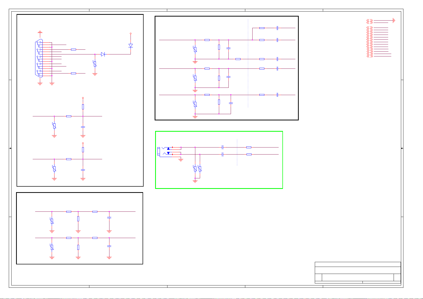
5
MB:5827
4
3
2
1
VGA INPUT
VD4
1N4148W /NC
+5V
12
XS2
5
15
VGASCL_IN
16 17
VGASCL_IN
VGASDA_IN
10
4
14
9
3
13
8
2
12
7
1
11
6
VSYNC#
BLU
HSYNC#
GRN
VGASDA_IN
RED
RV5
AVLC18S02015
RV6
AVLC18S02015
R158
100R
R164
100R
R147
100R
R152
100R
VGA_PLUGPWR
VGA_PLUGPWR
U0RX
U0TX
R157
10k
C167
100p/50V
R161
10k
C170
100p/50V
VGASCL
VGASDA
VD5
1 2
1N4148W
RV2
AVLC18S02015
VGA_PLUGPWR
D D
C C
Close to VGA CONN.
GRN
BLU BP
RED RP
R144
0R
RV1
AVLC18S02015
R150
0R
RV3
AVLC18S02015
R154
0R
RV4
AVLC18S02015
R146
75R
R153
75R
R156
75R
C161
47p/50V
C164
47p/50V
C166
47p/50V
R148
0R
VGA AUDIO INPUT
XS3
CKX-3.5-111\REFLOW
3
R
4
WR
2
WL
1
L
5
GND
RV7
AVLC18S02015
RV8
AVLC18S02015
C168 1u/10V
C169 1u/10V
Close to CONNECTOR
Close to MT5651
R160
30k
R162
30k
Close to Chip
R143
0R
R145
100R
R149
100R
R151
100R
R155
100R
VGA_R_IN
VGA_L_IN
C159
1.5n/50V
C160
10n/50V
C162
10n/50V
C163
10n/50V
C165
10n/50V
SOG
GP
VGACOM
GND2,3,4,5,6,8,9,10,11,12,13,14,15,16,17
+5V2,5,6,8,9,10,12,14,15,16,17
HSYNC8
VSYNC8
RP8
GP8
BP8
VGACOM8
SOG8
VGASDA8
VGASCL8
VGA_L_IN9
VGA_R_IN9
U0RX3
U0TX3
GND
+5V
HSYNC
VSYNC
RP
GP
BP
VGACOM
SOG
VGASDA
VGASCL
VGA_L_IN
VGA_R_IN
U0RX
U0TX
B B
ZHIYUNAN-20130114 更改通孔回 流封装耳机 端子
VGA SYNC SLICER
RV9
AVLC18S02015
RV10
AVLC18S02015
R167
0R
R170
0R
VSYNC#
HSYNC#
A A
5
R169
10k
R172
10k
R168
100R
R171
100R
C171
5p/50V
C172
5p/50V
VSYNC
HSYNC
4
Hisense Electric Co.,LTD
Hisense Electric Co.,LTD
Hisense Electric Co.,LTD
Title
Title
Title
VGA INPUT
VGA INPUT
VGA INPUT
Size Document Number Rev
Size Document Number Rev
Size Document Number Rev
MT5652
MT5652
MT5652
A3
A3
A3
Date: Sheet of
Thursday, November 07, 2013
Date: Sheet of
Thursday, November 07, 2013
Date: Sheet of
3
2
Thursday, November 07, 2013
1
1.0
1.0
1.0
177
177
177
Page 62

E
MB:5827
N3J
FAT_IN+
FAT_IN-
IF_AGC
AVDD12_RGB
AVSS12_RGB
D D
C C
AVDD33_DEMOD
AVSS33_DEMOD
AVDD12_DEMOD
AVSS12_DEMOD
AVDD33_VIDEO
AVSS33_VDAC
AVSS33_VDAC_BG
AVSS33_CVBS_1
AVSS33_CVBS_2
AVSS33_CPUPLL
AD19
AE19
AC17
AE18
AD18
AC18
AD17
W15
W17
M19
M20
V13
V16
V14
G15
Y17
ADCINP_DEMOD
ADCINN_DEMOD
IF_AGC
RF_AGC
AVDD12_RGB
AVSS12_RGB
AVDD33_DEMOD
AVSS33_DEMOD
AVDD12_DEMOD
AVSS12_DEMOD
AVDD33_VIDEO
AVSS33_VDAC
AVSS33_VDAC_BG
AVSS33_CVBS_1
AVSS33_CVBS_2
AVSS33_CPUPLL
MT5651_0928
VDACX_OUT
VDACY_OUT
HSYNC
VSYNC
COM
SOG
VGA_SCL
VGA_SDA
COM1
PB1P
PR1P
Y1P
SOY1
COM0
PB0P
PR0P
Y0P
SOY0
CVBS0P
CVBS1P
CVBS2P
CVBS3P
CVBS_COM
OSCL2
OSDA2
AC11
AC10
AB13
RP
AE12
GP
AB12
BP
AD12
AC12
AE9
AD9
AD14
AE14
AC14
AB14
AC13
AC16
AD16
AE16
AC15
AB15
AA14
Y14
W16
AB16
AA16
Y16
AA15
M21
M22
D
HSYNC
VSYNC
RP
GP
BP
VGACOM
SOG
VGASCL
VGASDA
COM0
PB0P
PR0P
Y0P
SOY0
TUNER_BYPASS _OUT
AV_bypass2
CVBS1P
CVBS_COM
OSCL2
OSDA2
R260
75R
C179
1u/10V
Analog Power
AVDD1V2
AVDD12_RGB
C173
100n/16V
AVDD3V3
AVDD33_DEMOD
C175
100n/16V
C176
100n/16V
C
AVDD3V3
AVDD33_VIDEO
AVDD1V2
AVDD12_DEMOD
C174
100n/16V
C177
100n/16V
B
GND2,3,4,5,6,7,9,10,11,12,13,14,15,16,17
+5V2,5,6,7,9,10,12,14,15,16,17
AVDD3V32,3,4,6,9,10,13
AVDD1V22,10,12
HSYNC7
VSYNC7
RP7
GP7
BP7
VGACOM7
SOG7
VGASDA7
VGASCL7
AINL_YPBPR9
AINR_YPBPR9
IF_AGC_H14
FAT_IN-14
FAT_IN+14
OSCL213
OSDA213
TUNER_BYPASS_OUT
9
A
GND
+5V
AVDD3V3
AVDD1V2
HSYNC
VSYNC
RP
GP
BP
VGACOM
SOG
VGASDA
VGASCL
AINL_YPBPR
AINR_YPBPR
IF_AGC_H
FAT_INFAT_IN+
OSCL2
OSDA2
TUNER_BYPASS _OUT
Tuner control
TR6
+5V
Close to Main Chip
R173
10k/NC
R174
10k
C178
47n/16V
IF_AGC_HIF_AGC
NEARLY YPBPR CONNECTOR
XS4
左
1
SIGNAL1
3
绿
SIGNAL3
2
GND
中
4
SIGNAL4
6
蓝
SIGNAL6
5
GND_1
右
7
SIGNAL7
9
红
SIGNAL9
8
GND_4
B B
S1
A A
D4
M2
MARK
M3
MARK
M1
MARK
M4
MARK
PB1_IN
PR1_IN
S2
D4
E
M5
MARK
S3
D4
M6
MARK
S4
D4
RV12
RV13
RV16
R194
18R
R186
18R
R178
18R
R190
56R
S5
D4
R181
56R
R193
56R
C184
47p/50V
D
R182
0R
C190
47p/50V
C191
47p/50V
NEARLY MT5651
R176
0R
R179
100R
R183
100R
R187
100R
R195
100R
1.5n/50V
C181
C182
22n/25V
C186
22n/25V
C188
22n/25V
C192
22n/25V
SOY0
Y0PY1_IN
COM0
PB0P
PR0P
RSAG7.308.0219
Component audio与AV audio in复用
NC11NC2
E1
C
C180
47n/16V
C185
1u/10V
AINL_YPBPR
AINR_YPBPR
CVBS1P
CVBS_COM
A
1.0
1.0
1.0
178
178
178
Y1_IN
XS5
1
3
2
4
6
5
RSAG7.308.0219
YPBPRL_IN0
YPBPRR_IN0
E2
SIGNAL1
白
SIGNAL3
GND
SIGNAL4
红
SIGNAL6
GND
2
BLM18PG121SN1
RV11
AVLC18S02015
RV14
NC11NC2
2
L19
C183
R177
47p/50V
75R/NC
C187
1u/10V
C189
1u/10V
Close to CONNECTOR Close to Chip
RV15
B
R175
100R
R180
0R
R185
30k
R188
30k
Hisense Electric Co.,LTD
Hisense Electric Co.,LTD
Hisense Electric Co.,LTD
Title
Title
Title
YPBPR/AV INPUT
YPBPR/AV INPUT
YPBPR/AV INPUT
Size Document Number Rev
Size Document Number Rev
Size Document Number Rev
MT5652
MT5652
MT5652
A3
A3
A3
Thursday, November 14, 2013
Date: Sheet of
Thursday, November 14, 2013
Date: Sheet of
Thursday, November 14, 2013
Date: Sheet of
Page 63

A
MB:5827
4
8
V/Y
3
7
R/PB
2
6
L/PR
51
GND
XS9
GND
+5V
AVDD3V3
3.3VS
AINL_YPBPR
AINR_YPBPR
VGA_L_IN
VGA_R_IN
AOMCLK_D
AOBCLK_D
AOLRCK_D
AOSDATA0_D
SPDIF_OUT
HDMI_ARC
AL0O
AR0O
U0RX
U0TX
U0TX
OIRI
5VS
MUTE_DRV632
TUNER_BYPASS _OUT
N3C
AINL_YPBPR
AINR_YPBPR
VGA_L_IN
VGA_R_IN
AVDD33_AADC
AVSS33_AADC
AVDD33_ADAC
AVSS33_ADAC
AVSS33_CLN
VMID_AADC
C199
100n/16V
+5V
SPDIF_OUT
A A
AB19
AB21
AB18
AB22
AB20
AC22
AC20
AB23
W14
AD22
Y18
AE23
W19
AA18
AD23
C200
1u/10V
L50
BLM18PG121SN1/NC
R200
100R
AIN1_L_AADC
AIN1_R_AADC
AIN2_L_AADC
AIN2_R_AADC
AIN3_L_AADC
AIN3_R_AADC
AIN4_L_AADC
AIN4_R_AADC
MPXP
AVDD33_AADC
AVSS33_AADC
AVDD33_ADAC
AVSS33_ADAC
AVSS33_CLN
VMID_AADC
MT5651_0928
R199
100R/NC
R201
100R/NC
C203
100p/50V
AVDD33_HPA
AVSS33_HPA
C202
10n/50V
AL0_ADAC
AR0_ADAC
AL1_ADAC
AR1_ADAC
AL2_ADAC
AR2_ADAC
ALIN
ASPDIFO0
AOBCK
AOLRCK
AOMCLK
AOSDATA0
AOSDATA1
AE24
AD25
AC24
AE25
AD24
AC25
AE6
AB4
AC8
AD7
AD8
AD6
AC7
AE22
V17
AL0O
AR0O
AL1O
AR1O
HDMI_ARC
SPDIF_OUT
AOBCLK_D
AOLRCK_D
AOMCLK_D
AOSDATA0_D
AVDD33_HPA
AVSS33_HPA
VD28
ICVL0518030FR
Analog Power
AVDD3V3
R196
0R
AVDD3V3
R197
0R
AVDD3V3
R198
0R
XS6
1
SIGNAL1
3
黄
SIGNAL3
2
GND
AVDD33_ADAC
AVDD33_AADC
C197
4.7u/10V
AVDD33_HPA
C194
4.7u/10V
1u/10V
C198
100n/16V
C201
100n/16V
C195
C196
10n/50V
R593
75R
Close to CONNECTORClose to IC
L3
1.8 uH
C478
47p/50V/NC
R590
C481
47p/50V
9
8
C475
47p/50V/NC
SCT1_AV_OUTTUNER_BYPASS_OUT SCT1_AV_OUT
VD27
ICVL0518030FR
0R
GND2,3,4,5,6,7,8,10,11,12,13,14,15,16,17
+5V2,5,6,7,8,10,12,14,15,16,17
AVDD3V32,3,4,6,8,10,13
3.3VS2,3,4,5,10,11
AINL_YPBPR8
AINR_YPBPR8
VGA_L_IN7
VGA_R_IN7
AOMCLK_D16,17
AOBCLK_D16,17
AOLRCK_D16,17
AOSDATA0_D16,17
SPDIF_OUT
HDMI_ARC10
AL0O17
AR0O17
U0RX3,7
U0TX3,7
U0TX3,7
OIRI3,5
5VS2,5,16
MUTE_DRV632
TUNER_BYPASS_OUT
CVBS OUT
AL1O
AR1O
R552
0R
C621
220p/50V/NC
R553
0R
C622
220p/50V/NC
Scart Audio Output
C496
R548
10k
1u/25V
C470
R724
220p/50V
82k/NC
C499
220p/50V
R546
10k
20k
AV-OUT AUDIO
1u/25V
R725
82k/NC
C494
R669
20k
C497
R554
47p/50V
6.8k
3
1
2
-INR
+INR
+INL14-INL13OUTL12UVP11GND10VDD9CP
R549
6.8k
C486
47p/50V
R670
R551
0R
DRV632 -MUTE: active low
5
6
GND4Mute
OUTR
R573
10k
R574
10k
R550
SCART1R_PA
0R
SCART1L_PA
C620
1u/16V
7
CN
VSS
8
DRV632
N42
100n/16V
4.7k/NC
C617
1u/16V
BLM18PG121SN1
C498
C616
22u/6.3V
R665
AVDD3V3
C495
100n/10V
L83
AVDD3V3
C493
4.7u/10V
R514
2.7k
MUTE_DRV632
C482
470p/50V
Audio Output
SCT1_AUL_OUT
VD26
ICVL0518030FR
SCT1_AUR_OUT
VD25
ICVL0518030FR
Hisense Electric Co.,LTD
Hisense Electric Co.,LTD
Hisense Electric Co.,LTD
Title
Title
Title
AUDIO IN/OUT/COAXIAL OUT
AUDIO IN/OUT/COAXIAL OUT
AUDIO IN/OUT/COAXIAL OUT
Size Document Number Rev
Size Document Number Rev
Size Document Number Rev
MT5652
MT5652
MT5652
A3
A3
A3
Date: Sheet of
Thursday, November 07, 2013
Date: Sheet of
Thursday, November 07, 2013
Date: Sheet of
Thursday, November 07, 2013
179
179
179
1.0
1.0
1.0
SCART1L_PA
R575
470R
SCART1R_PA
R579
470R
C480
470p/50V
A
Page 64
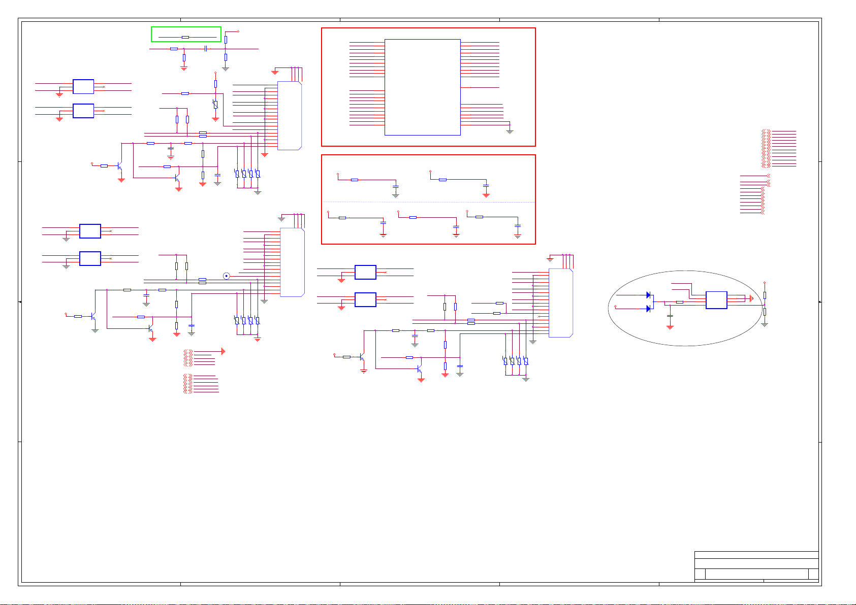
5
MB:5827
R202
CEC HDMI_CEC
22R/NC
R203
HDMI_ARC HDMI1_ARC
180R
R204
82R
N32
HDMI_2_RX_2
HDMI_2_RX_2B
HDMI_2_RX_0
HDMI_2_RX_0B
3.3VS
1
2
3
1
2
3
VN
AOZ8905
N31
VN
AOZ8905
1
2
3
1
2
3
R227
47k
N37
VN
AOZ8905
N38
VN
AOZ8905
1
CH46CH1
NC
CH34CH2
CH46CH1
NC
CH34CH2
3.3VS
5
5
R213
47k
CH46CH1
5
NC
CH34CH2
CH46CH1
5
NC
CH34CH2
3
V14
MMBT3904LT1
2
HDMI_1_RX_C
HDMI_1_RX_CB
HDMI_1_RX_1
HDMI_1_RX_1B
3
1
MMBT3904LT1
2
HDMI_2_RX_1
HDMI_2_RX_1B
HDMI_2_RX_C
HDMI_2_RX_CB
HDMI_2_HPD
R206
CEC
100R
HDMI1_5V
R207
R208
47k
47k
HDMI_1_SCL
HDMI_1_SDA
R211
HDMI1_5V
47k
V12
HDMI_1_HPD
HDMI2_5V
HDMI_2_SCL
HDMI_2_SDA
R225
47k
HDMI2_5V
R228
47R
1
C212
100n/16V
3
MMBT3904LT1
2
R438
0R
V15
GND2,3,4,5,6 ,7,8,9,11,12,13,14,15,16,17
AVDD3V32,3,4,6,8,9,13
AVDD1V22,8,12
3.3VS2,3,4,5,11
+5V2,5,6,7,8,9,12,14,15,16,17
HDMI_ARC9
HDMI_1_SCL5
HDMI_1_SDA5
HDMI_2_SCL5
HDMI_2_SDA5
HDMI_2_HPD5
R209 100R
R210 100R
R407
0R
C205
100n/16V
R214
47R
3
1
V13
MMBT3904LT1
2
R221
R222
47k
47k
R223 100R
R224 100R
R226
1k
R229
C213
100k
100n/16V
GND
AVDD3V3
AVDD1V2
3.3VS
+5V
HDMI_ARC
HDMI_1_SCL
HDMI_1_SDA
HDMI_2_SCL
HDMI_2_SDA
HDMI_2_HPD
HDMI_1_RX_0
HDMI_1_RX_0B
D D
HDMI_1_RX_2
HDMI_1_RX_2B
C C
B B
C204
1u/10V
RV22
R212
1k
R215
100k
3.3VS
TR1
R439
0R/NC
C206
100n/16V
R205
10k/NC
R382
10k/NC
+5V
HDMI1
HDMI_1_RX_2
HDMI_1_RX_2B
HDMI_1_RX_1
HDMI_1_RX_1B
HDMI_1_RX_0
HDMI_1_RX_0B
HDMI_1_RX_C
HDMI_1_RX_CB
CEC1
HDMI1_ARC
RV28
RV26
RV27
AVLC18S02015
AVLC18S02015
AVLC18S02015
HDMI2
HDMI_2_RX_2
HDMI_2_RX_2B
HDMI_2_RX_1
HDMI_2_RX_1B
HDMI_2_RX_0
HDMI_2_RX_0B
HDMI_2_RX_C
HDMI_2_RX_CB
CEC1
RV40
RV38
RV39
AVLC18S02015
AVLC18S02015
AVLC18S02015
4
RV29
AVLC18S02015
RV41
AVLC18S02015
1
2
3
4
5
6
7
8
9
10
11
12
13
14
15
16
17
18
19
XS7
DC1R019JB1
1
2
3
4
5
6
7
8
9
10
11
12
13
14
15
16
17
18
19
DATA2+_0
DATA2S
DATA2-_2
DATA1+_3
DATA1S
DATA1-_5
DATA0+_6
DATA0S
DATA0-_8
CLK+_9
CLKS
CLK-_11
CEC
NC
SCL
SDA
CEC/GND_16
+5V_17
HPDET
DATA2+_0
DATA2S
DATA2-_2
DATA1+_3
DATA1S
DATA1-_5
DATA0+_6
DATA0S
DATA0-_8
CLK+_9
CLKS
CLK-_11
CEC
NC
SCL
SDA
CEC/GND_16
+5V_17
HPDET
XS8
DC1R019JB1
3
N3D
P4
HDMI_1_RX_0
HDMI_1_RX_0B
HDMI_1_RX_1
HDMI_1_RX_1B
HDMI_1_RX_2
HDMI_1_RX_2B
HDMI_1_RX_C
HDMI_1_RX_CB
HDMI_1_SCL
HDMI_1_SDA
23
GND120GND221GND322GND4
HDMI_1_HPD
HDMI_2_RX_0
HDMI_2_RX_0B
HDMI_2_RX_1
HDMI_2_RX_1B
HDMI_2_RX_2
HDMI_2_RX_2B
HDMI_2_RX_C
HDMI_2_RX_CB
HDMI_2_SCL
HDMI_2_SDA
HDMI_2_HPD
Analog Power
AVDD3V3
R216
0R
AVDD1V2
R218
AVDD12_HDMI_1_RX
UD_RX1_2
UD_RX1_2B
UD_RX1_0
UD_RX1_0B
3.3VS
0R
N40
1
2
3
AOZ8905
N41
1
2
3
AOZ8905
R491
1
47k
23
GND120GND221GND322GND4
AVDD33_HDMI_RX
CH46CH1
VN
CH34CH2
CH46CH1
VN
CH34CH2
3
V26
MMBT3904LT1
2
HDMI_1_RX_0
P3
HDMI_1_RX_0B
R2
HDMI_1_RX_1
R1
HDMI_1_RX_1B
R4
HDMI_1_RX_2
R3
HDMI_1_RX_2B
N4
HDMI_1_RX_C
N3
HDMI_1_RX_CB
P5
HDMI_1_SCL
P6
HDMI_1_SDA
T8
HDMI_1_HPD
U2
HDMI_2_RX_0
U1
HDMI_2_RX_0B
U4
HDMI_2_RX_1
U3
HDMI_2_RX_1B
V4
HDMI_2_RX_2
V3
HDMI_2_RX_2B
T4
HDMI_2_RX_C
T3
HDMI_2_RX_CB
T5
HDMI_2_SCL
T6
HDMI_2_SDA
T7
HDMI_2_HPD
MT5651_0928
100n/16V
AVDD1V2
C209
100n/16V
UD_RX1_1
5
NC
UD_RX1_1B
UD_RX1C
5
NC
UD_RX1CB
R486
47k
HDMI_3_HPD
C207
UD_HDMI1_5V
R481
47R
R219
0R
UD_HDMISCL_1
UD_HDMISDA_1
C327
100n/16V
1
3
2
AVDD12_HDMI_1_RX
AVDD12_HDMI_2_RX
AVDD12_HDMI_3_RX
AVDD33_HDMI_RX
AVDD33_HDMI_3_RX
AVSS33_HDMI_RX
AVSS33_HDMI_3_RX
AVDD3V3
AVDD12_HDMI_2_RX
UD_HDMI1_5V
R479
0R
V25
MMBT3904LT1
HDMI_3_RX_0
HDMI_3_RX_0B
HDMI_3_RX_1
HDMI_3_RX_1B
HDMI_3_RX_2
HDMI_3_RX_2B
HDMI_3_RX_C
HDMI_3_RX_CB
HDMI_3_SCL
HDMI_3_SDA
HDMI_3_HPD
HDMI_CEC
R217
0R
R475
47k
R484
1k
R485
100k
Y25
Y24
W25
W24
V25
V24
AA25
AA24
W3
W4
W5
U5
W1
AVDD12_HDMI_1_RX
W2
AVDD12_HDMI_2_RX
AB24
AVDD12_HDMI_3_RX
N2
AVDD33_HDMI_RX
AB25
AVDD33_HDMI_3_RX
N7
AVSS33_HDMI_RX
R18
AVSS33_HDMI_3_RX
AVDD33_HDMI_3_RX
AVDD1V2
C211
100n/16V
R476
47k
UD_CEC1
R308 100R
R397 100R
C322
100n/16V
HDMI_3_RX_0
HDMI_3_RX_0B
HDMI_3_RX_1
HDMI_3_RX_1B
HDMI_3_RX_2
HDMI_3_RX_2B
HDMI_3_RX_C
HDMI_3_RX_CB
HDMI_3_SCL
HDMI_3_SDA
HDMI_3_HPD
HDMI_CEC
C208
100n/16V
R220
AVDD12_HDMI_3_RX
0R
CEC1
HDMI3
UD_RX1_2
UD_RX1_2B
UD_RX1_1
UD_RX1_1B
UD_RX1_0
UD_RX1_0B
R945
UD_RX1C
0R/NC
UD_RX1CB
R943
0R/NC
RV66
RV67
AVLC18S02015
C210
100n/16V
RV58
RV69
AVLC18S02015
AVLC18S02015
AVLC18S02015
1
2
3
4
5
6
7
8
9
10
11
12
13
14
15
16
17
18
19
DATA2+_0
DATA2S
DATA2-_2
DATA1+_3
DATA1S
DATA1-_5
DATA0+_6
DATA0S
DATA0-_8
CLK+_9
CLKS
CLK-_11
CEC
NC
SCL
SDA
CEC/GND_16
+5V_17
HPDET
XS11
DC1R019JB1
2
23
GND120GND221GND322GND4
VD21
1
UD_HDMI1_5V
+5V
2
BAT54C
3
UD_HDMISDA_1
UD_HDMISCL_1
R941
4.7k
C554
100n/16V
N107
5
6
SCL
7
WP
8
VCC
24LC02B-I/SN
UD通道外挂EDID
1
UD_CEC1
UD_RX1C
UD_RX1CB
UD_RX1_0
UD_RX1_0B
UD_RX1_1
UD_RX1_1B
UD_RX1_2
UD_RX1_2B
HDMI_3_RX_CB
HDMI_3_RX_C
HDMI_3_RX_0B
HDMI_3_RX_0
HDMI_3_RX_1B
HDMI_3_RX_1
HDMI_3_RX_2B
HDMI_3_RX_2
HDMI_3_SCL
HDMI_3_SDA
HDMI_3_HPD
HDMI1_5V
UD_CEC1 10
UD_HDMISCL_110
UD_HDMISDA_110
UD_RX1C 2
UD_RX1CB 2
UD_RX1_0 2
UD_RX1_0B 2
UD_RX1_1 2
UD_RX1_1B 2
UD_RX1_2 2
UD_RX1_2B 2
+5V
R942
4.7k/NC
R690
0R
HDMI_3_RX_CB11
HDMI_3_RX_C11
HDMI_3_RX_0B11
HDMI_3_RX_011
HDMI_3_RX_1B11
HDMI_3_RX_111
HDMI_3_RX_2B11
HDMI_3_RX_211
HDMI_3_SCL11
HDMI_3_SDA11
HDMI_3_HPD11
HDMI1_5V
UD_HDMISCL_1
UD_HDMISDA_1
Vss4SDA
3
A2
2
A1
1
A0
A A
Hisense Electric Co.,LTD
Hisense Electric Co.,LTD
Hisense Electric Co.,LTD
Title
Title
Title
HDMI1/HDMI2/HDMI3
HDMI1/HDMI2/HDMI3
HDMI1/HDMI2/HDMI3
Size Docum ent Number Rev
Size Docum ent Number Rev
Size Docum ent Number Rev
MT5652
MT5652
MT5652
A2
A2
A2
Date: Sheet of10 17
Friday, October 18, 2013
Date: Sheet of10 17
Friday, October 18, 2013
Date: Sheet of10 17
5
4
3
2
Friday, October 18, 2013
1
1.0
1.0
1.0
Page 65

A
MB:5827
N3B
C22
TCON0
C23
TCON1
D24
TCON2
B24
TCON3
C25
TCON4
A24
TCON5
D22
TCON6
B25
TCON7
C24
TCON8
E24
TCON9
D25
TCON10
D23
TCON11
A25
TCON12
R319
0R
A23
AVDD33_LVDSA
G16
AVSS33_LVDSA
F17
AVSS33_LVDSA
E20
AVSS33_LVDSA
B23
AVDD12_LVDSA
H15
AVSS12_LVDSA
MT5651_0928
AVDD12_LVDSA
C306
100n/16V
AVDD3V3
C307
1u/10V
AVDD33_LVDSA
AVSS33_LVDSA
AVSS33_LVDSA
AVSS33_LVDSA
AVDD12_LVDSA
AVSS12_LVDSA
Analog Power
AVDD1V2
A A
R320
0R
AO0P
AO0N
AO1P
AO1N
AO2P
AO2N
AOCKP
AOCKN
AO3P
AO3N
AO4P
AO4N
AO5P
AO5N
AE0P
AE0N
AE1P
AE1N
AE2P
AE2N
AECKP
AECKN
AE3P
AE3N
AE4P
AE4N
AE5P
AE5N
A16
B16
A17
B17
A18
B18
A19
B19
A20
B20
A21
B21
A22
B22
D16
E16
C17
C16
E17
D17
C19
C18
E19
D19
C21
C20
E21
D21
AVDD33_LVDSA
C308
100n/16V
LVDSTX_AO0P
LVDSTX_AO0N
LVDSTX_AO1P
LVDSTX_AO1N
LVDSTX_AO2P
LVDSTX_AO2N
LVDSTX_AOCKP
LVDSTX_AOCKN
LVDSTX_AO3P
LVDSTX_AO3N
LVDSTX_AO4P
LVDSTX_AO4N
LVDSTX_AE0P
LVDSTX_AE0N
LVDSTX_AE1P
LVDSTX_AE1N
LVDSTX_AE2P
LVDSTX_AE2N
LVDSTX_AECKP
LVDSTX_AECKN
LVDSTX_AE3P
LVDSTX_AE3N
LVDSTX_AE4P
LVDSTX_AE4N
C309
1u/10V
LVDSTX_AO0P TX_AO0PH
LVDSTX_AO0N TX_AO0NH
LVDSTX_AO1P TX_AO1PH
LVDSTX_AO4P TX_AO4PH
LVDSTX_AO4N TX_AO4NH
LVDSTX_AECKP TX_AECKPH
LVDSTX_AECKN TX_AECKNH
LVDSTX_AE3N TX_AE3NH
LVDSTX_AE4P TX_AE4PH
LVDSTX_AE4N TX_AE4NH
TX_AO1NHLVDSTX_AO1N
TX_AO2PHLVDSTX_AO2P
TX_AO2NHLVDSTX_AO2N
TX_AOCKPHLVDSTX_AOCKP
TX_AOCKNHLVDSTX_AOCKN
TX_AO3PHLVDSTX_AO3P
TX_AO3NHLVDSTX_AO3N
TX_AE0PHLVDSTX_AE0P
TX_AE0NHLVDSTX_AE0N
TX_AE1PHLVDSTX_AE1P
TX_AE1NHLVDSTX_AE1N
TX_AE2PHLVDSTX_AE2P
TX_AE2NHLVDSTX_AE2N
TX_AE3PHLVDSTX_AE3P
TX_AO0PH13
TX_AO0NH13
TX_AO1PH13
TX_AO1NH13
TX_AO2PH13
TX_AO2NH13
TX_AOCKPH13
TX_AOCKNH13
TX_AO3PH13
TX_AO3NH13
TX_AO4PH13
TX_AO4NH13
TX_AE0PH13
TX_AE0NH13
TX_AE1PH13
TX_AE1NH13
TX_AE2PH13
TX_AE2NH13
TX_AE3PH13
TX_AE3NH13
TX_AECKPH13
TX_AECKNH13
TX_AE4PH13
TX_AE4NH13
TX_AO0PH
TX_AO0NH
TX_AO1PH
TX_AO1NH
TX_AO2PH
TX_AO2NH
TX_AOCKPH
TX_AOCKNH
TX_AO3PH
TX_AO3NH
TX_AO4PH
TX_AO4NH
TX_AE0PH
TX_AE0NH
TX_AE1PH
TX_AE1NH
TX_AE2PH
TX_AE2NH
TX_AE3PH
TX_AE3NH
TX_AECKPH
TX_AECKNH
TX_AE4PH
TX_AE4NH
2,5,6,7,8,9,10,14,15,16,17
GND2,3,4,5,6,7,8,9,10,11,13,14,15,16,17
+5V
AVDD1V22,8,10
AVDD3V32,3,4,6,8,9,10,13
+12V2,13,16,17
LVDS_PWR_EN4
3D_EN4
GND
+5V
AVDD1V2
AVDD3V3
+12V
LVDS_PWR_EN
3D_EN
LVDS POWER CONTROL
+5V
BLM18PG121SN1 /NC
BLM18PG121SN1 /NC
+12V
LVDS_PWR_EN
HI = > LVDS POWER ON
LO = > LVDS POWER OFF
L103
L101
L102
BLM18PG121SN1
L104
BLM18PG121SN1
R956
20k
当供电为
调节
C1006
1u/10V
+5V
时,注意
R167/R171/C186
C1005
100n/16V
1
V50
MMBT3904LT1
2 3
R167/R171
的比值,作用于
的值来调整开关导通时间,以调整
1
2
3
4
C1008
R955
2.2u/10V
56k
R954
56k
C1007
100n/16V/NC
S1
S2
S3
G
MOS
管的压差要大于
N108
AO4459
D1
D1
D2
D2
LVDS_VDD
8
7
6
5
的斜率。
VCC-Panel
C1003
10u/10V
3.3V
C1004
100n/16V
。
Hisense Electric Co.,LTD
Hisense Electric Co.,LTD
Hisense Electric Co.,LTD
Title
Title
Title
LVDS POWER CONTROL
LVDS POWER CONTROL
LVDS POWER CONTROL
Size Document Number Rev
Size Document Number Rev
Size Document Number Rev
MT5652
MT5652
MT5652
A3
A3
A3
Thursday, October 31, 2013
Date: Sheet of
Thursday, October 31, 2013
Date: Sheet of
Thursday, October 31, 2013
A
Date: Sheet of
1.0
1.0
1.0
1711
1711
1711
Page 66

A
MB:5827
DEMO POWER
C417
1u/16V
closed to Demod
C416
1u/16V
closed to Demod
C330
47p/50V/NC
R702
680R
C337
47p/50V/NC
15
11
SDA
10
SCL
9
NC4
8
NC3
7
IF+
6
IF-
5
IF AGC
4
NC2
3
2
1
NC1
SHARP-VA4N1BC1201/NC
C421
100n/16V
C423
100n/16V
R406
51R
TUNER_SDA
TUNER_SCL
DFAT_IN+
DFAT_IN-
IF_T_AGC
B3_3.3V
C428
100n/16V
B4_1.2V
C412
100n/16V
R403
51R
TUNER_SCL
TUNER_SDA
3V3-TUNER
TUNER-SW
C411
100n/16V
120mA
C415
100n/16V
FAT_IN-
FAT_IN+
C323
33p/50V
60mA
C414
100n/16V
C420
100n/16V
33p/50V
Near Tuner
Close to Tuner
C429
100n/16V
C50
22u/6.3V
C427
C422
100n/16V
100n/16V
R395 100R/NC
R396
100R/NC
C324
R494
4.7k
C436
10n/50V
BLM18PG121SN1
C430
10u/10V
L52
BLM18PG121SN1
C424
22u/6.3V
Si-Tuner POWER
+5V
10u/10V
OSCL0
OSDA0
IF_AGC_H
L79
1.2VD
C325
+3.3V_TUNER
N19
3
VIN
C326
100n/16V
SPX1117M3-ADJLD1117A-ADJ
1.25 x _1+180/110_ = 3.3V
27p/50V
R398
110R
R399
180R
R310
47k
C328
10n/50V
V24
AO3401L/NC
2
C457
1u/10V
1
R480 10k
R314 100R
R313 22k/NC
R309
22k
+3.3V_TUNER
C329
10u/10V
3
V20
1
TUNER-SW
2 3
4
VOUT
2
VOUT
ADJ
1
+3.3V_TUNER
TUNER_SW2
C365
47p/50V
C366
47p/50V
IF_AGC
RF_SW
ANT(5V)
C425
100n/16V
C281
100n/16V
14
IF_P
IF_N
GND
SDA
SCL
N25
LD1117A-3.3AZ1117H-3.3
3
VOUT
VIN
VOUT
ADJ
1
R437
0R
N24
AZ1117-1.2
3
VOUT
VIN
VOUT
ADJ
1
R473
0R
C333
1u/50V
C335
1u/50V
I2C Address:
Write:C0
Read:C1
此两款
tuner
10
IF_T_AGC
9
DFAT_IN+
8
DFAT_IN-
7
6
5
TUNER_SDA
4
TUNER_SCL
3
3V3-TUNER
2
TUNER-SW
1
CDT-9051324-10_ZLT
+5V
C49
C418
1u/16V
22u/6.3V
C193
C426
1u/16V
22u/6.3V
IFBPF
DFAT_IN-
DFAT_IN+
A A
U8
GND111GND212GND313GND4
Clock Out
+B1(3.3V)
4
2
0R/NC
R436
4
2
0R/NC
R472
L64
0.22 uH
L65
0.22 uH
均使用
C413
100n/16V
C419
100n/16V
18273
3.3V_Demod
C52
22u/6.3V
1.2V_Demod3.3V_Demod
C51
22u/6.3V
R700
1k
R701
1k
芯片
L34
BLM18PG121SN1
L35
BLM18PG121SN1
U9
GND112GND213GND314GND4
B1_3.3V
RF_SW
GND2,3,4,5,6 ,7,8,9,10,11,12,13,15,16,17
+5V2,5,6,7,8,9,10,12,15,16,17
DVDD3V32,3,5,11,12,16,17
OSCL03,11,16,17
OSDA03,11,16,17
IF_AGC_H8
FAT_IN-8
FAT_IN+8
TUNER_SCL
TUNER_SDA
C528
C538
27p/50V
B4_1.2V
L111
BLM18PG121SN1
B3_3.3V
B4_1.2V
L37
BLM18PG121SN1
L38
BLM18PG121SN1
DFAT_IN+
DFAT_IN-
C526 C534改为100n---20130705zhiyunan
C510 33p/50V
25.4MHz晶振
C511 33p/50V
R682 0R
R683 0R
B3_3.3V
C512
1u/10V
C514 1 00n/16V
R6994.7k/NC
R7080R
C515 1 00n/16V
C516
1u/10V
C531
1u/10V
R7220 R
R7230 R
GND
+5V
DVDD3V3
OSCL0
OSDA0
IF_AGC_H
FAT_INFAT_IN+
IF_AGC_H
R6934.7k
R6944.7k
12
Z3
JAS16D
C513
100n/16V
1.2VD
1.2VD
C529
100n/16V
C532
100n/16V
C526 1 00n/16V
C534 1 00n/16V
C535 1 00n/16V
C536 1 00n/16V
100n/16V
R6951 00R
R696100R
R698
0R
Demod_RST#2
TP7
XOUT
R697
1M
XIN
CLOCK_OUT#
22XO23XI24
25
26
27
28
29
30
31
32
33
34
35
36
XCKO
PLLVDD_25
PLLVSS_26
VDDC_27
CKI
SLADRS1
TSMD
VSS_31
VDDC_32
ADCVDD_33
ADCVSS_34
VREFL_35
VREFH_36
AINPI37AINNI38AINPQ39AINNQ40VPGM41SYRSTN42STSFLG143SRSFLG044SCL45SDA46VSS_4747VDDS_48
IF_IP
IF_IN
IF_QP
IF_QN
B3_3.3V
R684 100R
R689 20 k
C527
20
21
TNSDA
R7214.7k
TNSCL
B3_3.3V
19
AGCCNTR
R685
100R
C542
100n/16V
TC90537
R688
4.7k/NC
16
17
18
AGCCNTI
SLADRS0
B3_3.3V
R6914.7k/NC
R6920R
B3_3.3V
C533
100n/16V
N7
13
14
15
SBYTE
TC90537FG
12
VSS_13
RSEORF
SRCK
VDDS_14
11
PBVAL
SLOCK
RLOCK
SLPEN
VDDC_1
48
SRDT
PERR
GPIO2
GPIO1
GPIO0
VSS_2
10
9
8
7
6
5
4
3
2
1
B3_3.3V
C537
100n/16V
R686 100R
R687 100R
1.2VD
R7054.7k
R7074.7k
B3_3.3V
100n/16V
OSDA0
OSCL0
C530
RP32 22R
RP33 22R
R720 22 R
R719 22 R
R706 22 R
1 8
2
3
4 5
1 8
2
3
4 5
C431
TS1_OUT_D[7:0] 2
10p/50V/NC
TSI_SYNC
TS1_OUT_SYNC 2
TSI_CLK
TS1_OUT_CLK 2
TSI_VLD
TS1_OUT_VLD 2
7
6
7
6
TS1_OUT_D7 2
TS1_OUT_D6 2
TS1_OUT_D5 2
TS1_OUT_D4 2
TS1_OUT_D3 2
TS1_OUT_D2 2
TS1_OUT_D1 2
TS1_OUT_D0 2
Hisense Electric Co.,LTD
Hisense Electric Co.,LTD
Hisense Electric Co.,LTD
Title
Title
Title
SILICON TUNER
SILICON TUNER
SILICON TUNER
Size Docum ent Number Rev
Size Docum ent Number Rev
Size Docum ent Number Rev
MT5652
MT5652
MT5652
A2
A2
A2
Date: Sheet of13 17
Thursday, November 07, 2013
Date: Sheet of13 17
Thursday, November 07, 2013
Date: Sheet of13 17
A
Thursday, November 07, 2013
1.0
1.0
1.0
Page 67

A
MB:5827
GND2,3,4,5,6,7,8,9,10,11,12,13,14,16,17
+5V2,5,6,7,8,9,10,12,14,16,17
DVDD3V32,3,5,11,12,16,17
USB_DP_P04
USB_DM_P04
USB_DP_P14
USB_DM_P14
WIFI_EN4
6
4
GND
3
D+
GND5GND
2
D -
1
VCC
XP11
6
4
GND
3
D+
GND5GND
2
D -
1
VCC
XP13
3
4
47
PWRB1
10u/16V
46
FE1.1-HX
C517
100n/16V
C382
42
LED143LED244LED345LED4
HUB 3_3V
HUB 3_3V
HUB 3_3V
40
41
DRV
VD33
HUB 1_8VHUB 1_8V
39
TEST
VD33_OUT
100n/16V
500mA
38
VD5_IN
C518
L17 STPB2012-121PT
C357
10u/16V
Close to pin38(VD5_IN)
XRSTJ
DPU
DMU
REXT
VS_A
HUB 3_3V
36
BUS_B
35
34
33
32
31
30
29
28
27
26
25
USB3_DP
USB3_DM
BLM18PG121SN1
L68
37
DIS_REG
BUS_B
VBUSM
VSS_33
VD33_32
VD18_29
VD3_IN
VREG18
DP124DM123VSS_2222DP221DM220VD33_1919DP318DM317VSS_1616DP415DM414VD33_13
HUB 1_8V
HUB 3_3V
R159
+5V
signal only 8 mil
C354
100n/16V
R165
10k
R163
100k
500mA
R165, R163, C354 are close to pin 35 (VBUSM).
R184
100k
100k
HUB 3_3V
HUB 1_8V
300mA
300mA
R166
2.7k
2.7K+-1% close to pin 28
* 5 couples of DP, DM, must be at least
1500 mil with 15 of 45-degree-angle (USB-IF).
VD_PLL
C519
100n/16V
R704 5.1R
R703 5.1R
HUB 3_3V
HUB 1_8V
USB_DP_P0
USB_DM_P0
HUB 1_8V
C369
10u/16V
Close to pin26
+5V
C371
100u/16V
USB_HUB
5V_USB
R70910k
HUB 1_8V
Z2
1 2
JAM12D
HUB 3_3V
USB2_DM
USB2_DP
USB1_DM
USB1_DP
HUB 3_3V
100n/16V
C522
VD_PLL
C523
100n/16V
X'TAL 12MHZ
16~20pF/30~50ppm
A A
HUB 3_3V HUB 3_3V HUB 3_3V HUB 3_3V
C520
C521
100n/16V
100n/16V
Close to pin39
C525
10n/50V
N9
1
OVCB2
2
PWRB2
3
VD18_3
4
PWRB3
5
OVCB3
6
VSS
7
FE1_QFP48
OVCB4
8
PWRB4
9
VD_PLL
10
VS_PLL
11
XOUT
12
XIN
C524
100n/16V
48
OVCB1
13
+5V
10u/10V
C374
USB POWER
C370
C373
100n/16V
10u/10V
5V_USB
F2
12
C372
100n/16V
nanoSMDC200F-2
F4
nanoSMDC200F-2
12
5V_USB
5V_USB_WIFI
Near Connector
EQUAL LENGTH and DIFFERENTIAL
IMPEDANCE 90ohm
USB1_DP
USB1_DM
USB2_DP
USB2_DM
C341
10u/10V
C349
10u/10V
R434 0R
R435 0R
C338
10u/10V/NC
R440 0R
R441 0R
C350
10u/10V/NC
C339
10p/50V
C351
10p/50V
C340
10p/50V
C352
10p/50V
USB PORT 1
N103
3
I/O1
I/O2
4
GND
VP
ESDA6V8UB
USB PORT 2
I/O12I/O2
1
GND
ESDA6V8UB
2
1
N104
VP
GND
+5V
DVDD3V3
USB_DP_P0
USB_DM_P0
USB_DP_P1
USB_DM_P1
WIFI_EN
PIN 19 PIN 32 PIN 41PIN 27
PIN 13
Bypass CAP , close to each indicated pin
of FE1.1, and should not be removed.
WIFI
+5V
L31
BLM18PG121SN1
BLM18PG121SN1/NC
C342
100n/16V
L32
R408
10k
WIFI_CTRL
MMBT3904LT1
C343
2.2u/10V
R409
1k
V37
2
AO3401L
1
V38
2 3
PIN 3 PIN 29
3
C344
10u/10V
R410
1
4.7k
C353
100n/16V
PIN 9
EQUAL LENGTH and DIFFERENTIAL
IMPEDANCE 90ohm
C379
100n/16V
WIFI_EN
C346
10u/10V
USB_DM_P1
USB_DP_P1
C347
10p/50V
5V_USB_WIFI_M
10p/50V
C380
RV56
RV55
5V_USB_WIFI_M
USB_DM_P1
USB_DP_P1
WIFI_EN
N105
1
GND
C361
10p/50V
I/O12I/O2
ESDA6V8UB
5V_USB_WIFI
XP12
1
2
3
4
XP34
1
2
3
4
756
A
USB3_DPUSB3_DP
USB3_DM
C383
10u/10V
R443 0R
R445 0R
C363
10u/10V/NC
C360
10p/50V
USB PORT3
4
VP
3
Hisense Electric Co.,LTD
Hisense Electric Co.,LTD
Hisense Electric Co.,LTD
Title
Title
Title
USB
USB
USB
Size Document Number Rev
Size Document Number Rev
Size Document Number Rev
MT5652
MT5652
MT5652
A3
A3
A3
Monday, December 02, 2013
Date: Sheet of
Monday, December 02, 2013
Date: Sheet of
Monday, December 02, 2013
Date: Sheet of
6
4
GND
3
D+
GND5GND
2
D -
1
VCC
XP14
14 17
14 17
14 17
1.0
1.0
1.0
Page 68

5
MB:5827
SPEAKER Amplifier
I2C Address
= 0x6A
D D
C233
470n/50V
C238
C237
1u/50V/NC
220n/50V
L23
15.0 uH
15.0 uH
AVDDDVDD3V3
N21
1
OUT_A
2
PVDD_A
3
PVDD_A_7
4
BST_A
5
GVDD_OUT_31
6
SSTIMER
7
OC_ADJ
8
NC
9
AVSS
10
PLL_FLTM
11
PLL_FLTP
12
VR_ANA
C266
10u/10V
R265
10k
L24
C280
R281
2.2R/NC
10n/50V/NC
C C
VPA
L27
STPB2012-121PT
C246
220u/25V
C252
1u/25V
C261
C260
47n/16V
B B
A A
4.7n/50V
DVDD3V3
R302
18k
R262
15k
R299
470R
C268
100n/16V
5
C247
1u/25V
C253
2.2n/50V/NC
C262
4.7n/50V
C248
33n/50V
R293
22k
R249
470R
C263
47n/16V
L30
BLM18PG121SN1
AMP-Rout+
AMP-Rout-
C234
470n/50V
C239
220n/50V
C230
R282
2.2R/NC
10n/50V/NC
C243
33n/50V
C332
1u/25V
46
47
48
45
OUT_B
PVDD_B
PGND_AB
PGND_AB_2
TAS5707
AVDD13FAULT_13_1314MCLK15OSC_RES16DVSSO17VR_DIG18PDN_18_1819LRCLK20SCLK21SDIN22SDA23SCL
R301
C269
4.7u/10V
18k
R259
200R
C270
100n/16V
C267
100n/16V
4
1
2
3
4
5
6
AMP-Lout+
AMP-Lout-
470n/50V
220n/50V
10n/50V/NC
C231
C244
C235
C240
R283
2.2R/NC
C241
1u/50V/NC
L25
15.0 uH
470n/50V
220n/50V
L26
15.0 uH
R285
2.2R/NC
C236
C242
AMP-Lout+
AMP-LoutAMP-RoutAMP-Rout+
Woofer_INWoofer_IN+
C232
10n/50V/NC
33n/50V
C321
41
42
40
43
44
BST_B
PVDD_B_46
AVDD
BST_C
R266
10k
39
38
OUT_C
PVDD_C
PVDD_C_29
C271
4.7u/10V
4
37
PGND_CD
OUT_D
PGND_CD_5
PVDD_D_44
PVDD_D
BST_D
GVDD_OUT
VREG
AGND
GND
DVSS
DVDD
STEST
RESET_24_24
EPAD
24
AOSDATA0_D-AMP
AOBCLK_D-AMP
AOLRCK_D-AMP
AOMCLK_D-AMP
R267
10R/NC
1u/25V
36
35
34
33
32
31
30
29
28
27
26
25
49
MUTE_5707
RST_AMP
C249
33n/50V
C254
100n/16V
C264
100n/16V
C27222p/50V
C255
1u/25V
C257
10u/10V
C27422p/50V
C27322p/50V
C250
1u/25V
DVDD
C259
100n/16V
R251
100R/NC
R300
10k
R303 22R
R304 22R
R305 33R
R261 33R
R263 33R
R264 33R
C27522p/50V
3
XP22
AMP-Lout+
AMP-LoutAMP-RoutAMP-Rout+
8
7
L28
STPB2012-121PT
C251
220u/25V
L29
BLM18PG121SN1
R711
RST_AMP
0R
DVDD
AOSDATA0_D
靠近主IC放置
3
1
2
3
4
5
VPA
DVDD3V3
OPCTRL4
OSCL0
OSDA0
AOBCLK_D
AOLRCK_D
AOMCLK_D
XP23
6
MTUE CIRCUIT
+5V +12V
R291
R290
1k/NC
220R
R294
1k
12
R248
VD12
0R/NC
1N4148W
R254
47k
9,17
9,17
9,17
VD10
1 2
1N4148W
R298
56k
AOMCLK_D-AMP
AOBCLK_D-AMP9,17
AOLRCK_D-AMP
AOSDATA0_D-AMP
VD9
1 2
1N4148W /NC
R295
0R
C258
220u/16V
AMP_MUTE
2
POP_MUTE_DRV632
VD20
1N4148W
2 3
R253
0R
C265
100n/16V
AOMCLK_D-AMP
AOBCLK_D-AMP
AOLRCK_D-AMP
AOSDATA0_D-AMP
2
1N4148W /NC
1 2
V22
MMBT3906LT1
1
DVDD3V3
R280
4.7k/NC
1 2
1
+12V
R286
0R
R288
0R/NC
R289
0R
GND
+5V
+12V
+14V
5VS
DVDD3V3
3.3VS
OSCL0
OSDA0
AOMCLK_D
AOBCLK_D
AOLRCK_D
AOSDATA0_D
OPCTRL4
AMP_MUTE
HPDET#
AL0O
AR0O
RST_AMP
MUTE_5707
POP_MUTE_DRV632
Woofer_IN+
Woofer_IN-
R292
10k/NC
C256
10u/10V/NC
5VS
+5V
MUTE_5707
VD19
VD7
12
1N4148W/NC
VD8
1N4148W/NC
VD11
1 2
1N4148W
GND2,3,4,5,6,7,8,9,10,11,12,13,14,15,17
+5V2,5,6,7,8,9,10,12,14,15,17
+12V2,12,13,17
+14V2,17
5VS2,5
DVDD3V32,3,5,11,12,17
3.3VS2,3,4,5,10,11
OSCL03,11,14,17
OSDA03,11,14,17
AOMCLK_D9,17
AOBCLK_D9,17
AOLRCK_D9,17
AOSDATA0_D9,17
OPCTRL43,4
AMP_MUTE4
HPDET#4,17
AL0O9,17
AR0O9,17
RST_AMP17
POP_MUTE_DRV632
R234
0R/NC
R239
4.7k
1
V23
2 3
MUTE_570716,17
Woofer_IN+16,17
Woofer_IN-16,17
+5V
MUTE1
R297
47k/NC
16,17
12
C245
100u/16V
R287
68k
1 2
R296
MUTE
10k
R247
47k
VD13
1N4148W
Hisense Electric Co.,LTD
Hisense Electric Co.,LTD
Hisense Electric Co.,LTD
Title
Title
Title
SPEAKER/MUTE
SPEAKER/MUTE
SPEAKER/MUTE
Size Document Number Rev
Size Document Number Rev
Size Document Number Rev
MT5652
MT5652
MT5652
A3
A3
A3
Date: Sheet of
Friday, October 18, 2013
Date: Sheet of
Friday, October 18, 2013
Date: Sheet of
Friday, October 18, 2013
1
15 17
15 17
15 17
1.0
1.0
1.0
Page 69

+14V
MB:5827
+12V
DVDD3V3
L93
BLM18PG121SN1
L94
BLM18PG121SN1 /NC
AOMCLK_D-AMP
AOBCLK_D-AMP
AOLRCK_D-AMP
AOSDATA0_D-AMP
OSCL0
OSDA0
MUTE_5707
R311
18k
R312
C386
15k
10n/50V
DVDD3V3
R452
15k/NC
DVDD3V3
R453
15k
RST_AMP
VPA
STPB3216-121PT
VPA
R316 10k
R469 22R
R470
R450 470R
R451
470R
R317 200R
R468
10k
R465
100R/NC
L77
STPB3216-121PT
L78
C385
1u/25V
22R
C404 4.7n/50V
C348 47n/16V
C406
C356 47n/16V
R318
C393 4.7u/10V
C394 100n/16V
C397
R315 22k
4.7n/50V
18k
NC/2.2n/50V
C401
1u/10V
C345
220u/25V
C408 1u/25V
C399 1u/25V
15
21
20
22
24
23
19
8
11
12
10
16
18
6
7
14
25
N36
MCLK
SCLK
LRCLK
SDIN
SCL
SDA
PDN
PBTL
PLL_FLTP
VR_ANA
PLL_FLTM
OSC_RES
VR_DIG
SSTIMER
OC_ADJ
A_SEL
RESET_24
3
PVDD_A12PVDD_A2
45
PVDD_B144PVDD_B2
TAS5711
PGND_AB147PGND_AB2
48
C396 1u/25V
C395 1u/25V
35
41
PVDD_D134PVDD_D2
PVDD_C140PVDD_C2
AVSS
DVSSO
PGND_CD137PGND_CD2
9
17
38
BLM18PG121SN1
13
AVDD
DVSS28GND29AGND
30
DVDD3V3
L91
C403
10u/16V
C389 100n/16V
27
DVDD
OUT_A
BST_A
BST_B
OUT_B
GVDD_OUT1
GVDD_OUT2
OUT_C
BST_C
BST_D
OUT_D
VREG
STEST
EPAD
26
49
DVDD3V3
L92
BLM18PG121SN1
C405 10u/16V
C392 100n/16V
1
C407
4
33n/50V
43
C409
33n/50V
46
5
C387
1u/50V
32
C390 1u/50V
39
42
33
36
31
C402
100n/16V
WOOFER AMP
R466
15.0 uH
L54
15.0 uH
4.7R/NC
C358
470n/50V
C362
470n/50V
R467
4.7R/NC
L55
Woofer_IN+
Woofer_IN-
C400 1n/50V/NC
C388
220n/50V
C391
220n/50V
C398 1n/50V/NC
Woofer_IN+
C384
470n/50V/NC
Woofer_IN-
XIGUO-20120924
16,17
9
9,17
9,17
9,17
AVDD3V32,3,4,6,8,9,10,13
GND2,3,4,5,6,7,8,9,10,11,12,13,14,15,16
+5V2,5,6,7,8,9,10,12,14,15,16
+12V2,12,13,16
+14V2
5VS2,5,16
DVDD3V32,3,5,11,12,16
3.3VS2,3,4,5,10,11
OSCL03,11,14,16
OSDA03,11,14,16
AOMCLK_D9,16
AOBCLK_D9,16
AOLRCK_D9,16
AOSDATA0_D9,16
HPDET#4
MUTE_HP4
AL0O9
AR0O9
RST_AMP16
MUTE_570716,17
POP_MUTE_DRV632
MUTE_DRV632
Woofer_IN+16,17
Woofer_IN-16,17
AOMCLK_D-AMP
AOBCLK_D-AMP9,17
AOLRCK_D-AMP
AOSDATA0_D-AMP
AVDD3V3
GND
+5V
+12V
+14V
5VS
DVDD3V3
3.3VS
OSCL0
OSDA0
AOMCLK_D
AOBCLK_D
AOLRCK_D
AOSDATA0_D
HPDET#
MUTE_HP
AL0O
AR0O
RST_AMP
MUTE_5707
POP_MUTE_DRV632
MUTE_DRV632
Woofer_IN+
Woofer_IN-
AOMCLK_D-AMP
AOBCLK_D-AMP
AOLRCK_D-AMP
AOSDATA0_D-AMP
R455
AL0O
0R
C618
220p/50V/NC
AR0O
R457
0R
C619
220p/50V/NC
C443
1u/25V
R676
82k/NC
1u/25V
R677
82k/NC
10k
C441
R268
C276
220p/50V
R379
10k
AV-OUT AUDIO
C278
220p/50V
20k
HeadPhone Output
R666
20k
C444
R458
47p/50V
6.8k
1
2
-INR
+INR
+INL14-INL13OUTL12UVP11GND10VDD9CP
R269
6.8k
C440
47p/50V
R667
R456
0R
DRV632 -MUTE: active low
3
5
GND4Mute
OUTR
R459
10k
R460
10k
R454
0R
C615
1u/16V
6
VSS
HPOUTR
7
CN
8
HPOUTL
DRV632
N35
100n/16V
4.7k/NC
C614
1u/16V
BLM18PG121SN1
C447
C613
22u/6.3V
R664
L67
AVDD3V3
C442
100n/10V
4.7u/10V
AVDD3V3
C277
R377
MUTE_DRV632
2.7k
XIGUO-20120924
MUTE_HP
R433
100n/16V
HEADPHONE
XS10
CKX-3.5-111\REFLOW
3
R
4
WR
2
WL
1
L
5
GND
POP_MUTE_DRV632
DVDD3V3
R273
4.7k
1 2
0R
1N4148W
C378
HPOUTR
HPOUTL
VD18
R681
47k
R271
4.7k/NC
R680
4.7k
R678
10k
MMBT3904LT1
+5VAVDD3V3
R461
100k
1
V19
+5V
R274
5.6k
10k
2 3
VD14
1 2
1N4148W/NC
R270
4.7k
R655
33R/NC
DVDD3V3
R272
4.7k/NC
MUTE_DRV632
R679
XIGUO-20120924
1
C279
2.2u/10V
V40
3
MMBT3904LT1
2
+5V
R654
10k
HPDET#
R651
10k
XIGUO-20120924
Page 70
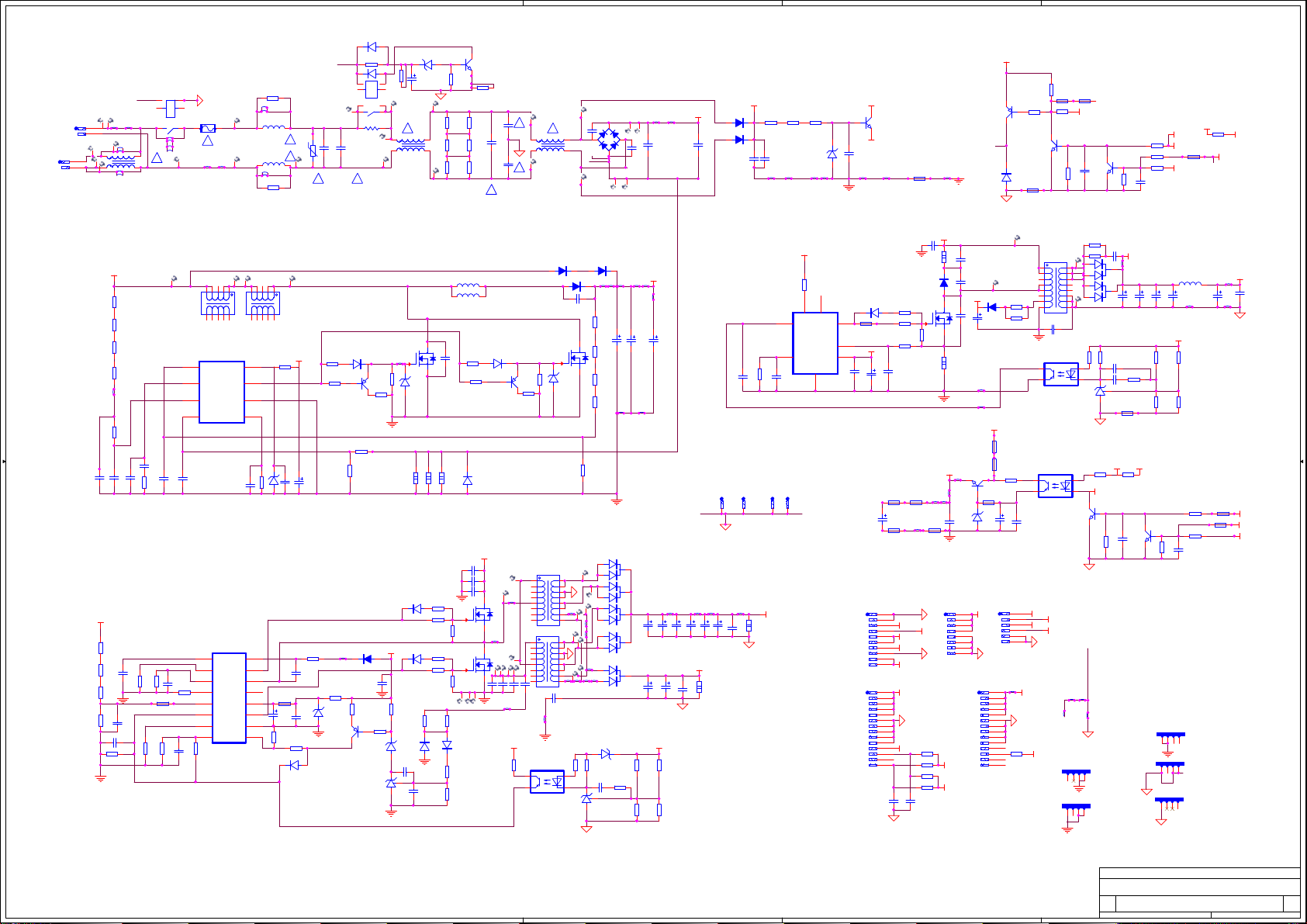
5
<RevCode>
<RevCode>
<RevCode>
PB:5506
LTDN85XT910XWAM3D PB:5506
A
VD843
1N4148W
RV801
TVR14561KOG9W
!
K801
HF162F
C801
470n/AC275V
C814
470n/AC275V
K802
HF162F
1 2
A
3 4
68 57
W881
W882
W829
W838
!
F803
1 2
!
W809
W833
XP801
XP802
1
2
W885
1
2
W886
W883
W880
L803
W879
LCL-3505-HC\BBY
W884
D D
W876
W877
R966
330R
L922
10uH
!
L923
10uH
!
W875
W874
R967
330R
R807
15k
3
2
8 7
RT801
SCK200510LS
!
4
VD846
1N4148W
R895
4
0R
1
56
L801
LCL-3505-HC\BBY
3
VZ815
BZT52C10
C859
47u/50V
!
V939
12
MMBT2222A
R884
R808
0R
200K
C802
C803
470n/AC275V
R801
1M
R802
1M
R803
1M
220p/AC400V
R804
!
1M
R805
1M
R806
!
1M
C804
220p/AC400V
!
!
L802
LCL-3505-HC\BBY
470p/1000VV
C805
B
VB802
VB801
KBJ1006G
KBJ1006G
M827
C807
220n/450V
M847
C806
470p/1000VV
W865
W864
C808
220n/450V
300V
VD908
FR107
VD909
FR107
10n/630V
300V-1
R954
R955
R953
510k
510k
510k
VDD
W811
C902
100n/50V
W825
C942
W831
C946
10n/630V
W810
VZ901
MSZ16T1G
W808
20V
V935
MMBT2222A
W842
2
12V
R925
4.7k
R905
R904
0R
R962
4.7k
V933
MMBT2222A
VD914
1N4148W
R899
0R
0R
P
R903
0R
V938
MMBT2222A/nc
R938
10k
C871
100n/50V
R964
4.7k/nc
V815
MMBT2907
A
W830
R890
0R
1 2
R897
100k/nc
C870
100n/nc
R937
10k
R898
100k/nc
1
19V-ON
STB
12V
19V-ON
19V-ON
R901
0R
DET
R902
0R
C822
PFC
R881
0R
VD906
1N4148W
VDD
C914
47u/50V
XP805
XP803
C861
1n/50V
220n/450V
R887
0R
R883
0R
XP808
W873
T901
1
2
3
4
R947
R946
5
10R
10R
6
8
7
BCK-04HA
C850
470p/AC400V
4
N894
PC817B
R919
1k
4
N892
PC817B
C910
470n/50V
1
BRI
2
SW
3
12V
4
STB
5
6
24V
R965
0R
SW
R945
56k/2W
VD910
UF4007
V934
R908
FQPF8N80C
33R
R950
56R
R949
1k
C941
330p/50V
R885
R888
0R
0R
R889
0R
W850
1
2
3
BRI
4
SW
5
12V
6
7
STB
8
9
10
18V
1
24V
2
3
4
5
6
7
8
9
10
R957
11
0R
DET
12
13
14
C866
1n/50V
C937
2.2n/2KV
C938
nc
20V
VD907
R958
nc
VCC
XP806
SW
BRI
W821
C912
470n/50V
C940
56p/1000VV
R948
0.47R/2W
W814
W815
V932
BCP56-10T1G
W822
VZ814
MSZ16T1G
1
2
3
4
5
6
7
8
R959
nc
R960
0R
12V
XP804
FR104
R886
0R
20V
C939
47u/50V
C911
10u/50VV
1
2
3
4
5
6
7
8
9
10
11
12
13
14
R911
5.1k
W816
R894
W832
0R
N902
NCP1271D65R2G
R951
12k
C928
1n/50V
G805
G806
1
24V
R862
2.2k/2W
300V-1
R952
1k
8
7
5
HV
2
NC
Drv
FB
3
CS
Skip/latch
6
VCC
GND
4
C854
100n/50V
C913
10u/50VV
1
1
VD811
VD813
1N5408\BBY
300V
R811
1M
R812
1M
C828
104/50V
R831
1M
R832
1M
R833
680k
R834
8.2k
C835
1n/50V
R841
2k
R813
1M
R829
1M
W820
R846
470K
C819
104/50V
C820
104n/50V
C818
1n/50V
R827
200k
C821
102/50V
PFC
R836
R835
C832
1u/50V
C831
470n/50V
C833
2.2M
4.7k
1u/50V
R935
15k
R880
0R
R838
C834
R839
15k
1n/50V
8.2k
C C
B B
A A
N810
1
FB
Vcontrol2Drv
IN3GND
4
CS
NCP1653ADR2G
C817
100p/50V
R936
39k
45
45
N831
NCP1396ADR2G
1
CSS
2
Fmax
3
Ctimer
4
RT
5
BO
6
FB
7
DT
FF8SF
9876
9876
Mupper
Mlower
11023
11023
VCC
VM
C825
102/50V
Vboot
Vcc
GND
L811
L813
BK-35-BD
BK-35-BD
HB
NC
11023
45
11023
45
L812
L814
BK-35-BD
BK-35-BD
9876
9876
VD815
R849
10k
VD832
1N4148W
VCC
C827
10u/50VV
C836
100n/50V
C837
100n/50V
R819
22R
MBR0520
R817
V812
5.1k
MMBT2907
R875
R818
22R
22
B
R874
1.5k
R871
nc
VD831
R842
20R
W878
R843
20R
VZ831
BZT52C18
V814
MMBT2907
MURS160T3G
C860
100n/50V
R844
2k
VZ832
3V3
N883
TL431
VCC
R845
10k
2 3
R828
20R
8
7
6
5
VZ812
R815
BZT52C18
51K
C816
100n/50V
16
15
14
13
R879
0R
12
11
C838
10
10u/50VV
9
R847
5.1k
V810
CS12N60
W812
R821
0.22R/2W
R848
1k
VD836
1N4148W
VZ811
BZT52C18
1
VD840
1N4148W
VD841
1N4148W
R820
0.22R/2W
C839
470n/63V
C840
100n/50V
C826
470p/2KV
R856
20R
R857
68R
R859
20R
R860
68R
R851
100k
L924
L925
R822
0.22R/2W
C824
NC
C813
220n/450V
C823
220n/450V
R850
100k
VD835
1N4148W
R852
2k
R853
3.3k
V856
10N60
R858
5.1k
R861
5.1k
R840
22R
V857
10N60
R873
22R
VD833
1N4148W
PFC
VD816
MBR0520
V813
MMBT2907
W819
C853
nc
W806
W818
C849
15n/1KV
C842
15n/1000V
C841
56p/1000VV
VCC
R854
1k
1N5408\BBY
VD812
SFF1506CT
V811
CS12N60
R837
5.1k
R816
22
T831
BCK-04TQ
T832
BCK-04TQ
4
N893
PC817B
220p/2000VV
VZ813
BZT52C18
R830
nc
W835
W837
C851
470p/AC400V
W860
R855
1k
1
23
N884
TL431
W862
W834
W805
C809
R823
680K
R824
620K
R825
620K
R826
nc
W856
W857
VD845
W852
SRF30100
W853
VD842
SRF30100
R863
1k
C852
470n/63V
1
2 3
W817
W827
W824
VZ833
3V3
R864
1k
W836
W826
VD838
SRF30100
VD844
SRF30100
VD839
SRF30100
C843
1000u/35V
C848
1000u/35V
W813
PFC
W804
C810
100u/450V
C811
100u/450V
C812
100u/450V
C929
1n/50V
G803
G802
1
1
C844
C846
1000u/35V
1000u/35V
W840
W839
C845
1000u/35V
C857
C867
1000u/35V
100n/50V
24V
R865
R866
82k
10k
R869
R868
1k
nc
C847
1000u/35V
18V
R870
2.2k/2W
W854
C858
1000u/35V
C868
100n/50V
W859
9
10
11
13
12
14
15
16
V936
MMBT2222A
W889
W844
Q801
123
Q802
123
R944
27R
R923
1k
1
23
1
23
W887
RSAG5.861.156
4
RSAG7.308.0211
4
R943
27R
C934
470p/1KV
12V-1
W849
C945
VD905
1500u/25V
VD911
C935
1500u/25V
R924
1k
C926
nc
C927
470n/63V
1
N885
TL431
2 3
R882
0R
R922
12V
1k
R896
0R
P
R961
4.7k
C856
100n/50V
W863
C944
1500u/25V
R872
1k
12V
V937
MMBT2222A
R963
nc
Q803
Q804
Q805
R940
nc
R942
nc
123
123
123
L921
LEI-038H
C943
1500u/25V
W848
12V-1
R939
15k
R941
3.9k
R956
4.7k
R867
nc
C855
nc
RSAG5.861.155
4
RSAG5.861.155
4
RSAG5.861.156
4
C936
1500u/25V
R892
0R
R900
0R
W855
W828
12V
C863
100n/50V
STB
DET
12V
5
4
Title
Title
Title
Title
Title
Title
<Title>
<Title>
<Title>
<Title>
<Title>
<Title>
Size Document Number Rev
Size Document Number Rev
Size Document Number Rev
Size Document Number Rev
Size Document Number Rev
Size Document Number Rev
<Doc>
A2
<Doc>
A2
<Doc>
A2
<Doc>
A2
<Doc>
A2
<Doc>
A2
Date: Sheet
Date: Sheet of
Date: Sheet of
Date: Sheet of
Date: Sheet of
3
2
Date: Sheet of
1
of
1 1Wednesday, October 16, 2013
1 1Wednesday, October 16, 2013
1 1Wednesday, October 16, 2013
1 1Wednesday, October 16, 2013
1 1Wednesday, October 16, 2013
1 1Wednesday, October 16, 2013
Page 71

1
1
2
2
3
3
4
4
5
5
6
6
7
7
8
8
D D
C C
B B
A A
Title
Number RevisionSize
A2
Date: 2013-9-12 Sheet of
File: E:\ \..\LED55K680X3DU_DY_5567_C.SCHDOCDrawn By:
103/630V
C842
STB
BLSW
474/50V
C831
8k2
R834
47n/CJ
C839
1N4148
VD832
5k1
R847
10k
R846
27R
R843
15K
R837
104/50V
C837
105
C833
105
C832
15k
R838
4K7
R835
2M2
R836
47uF/25V
C838
102/50V
C834
1k
R854
2K
R844
1K
R848
10K
R845
39K
R840
3K9
R839
22R
R842
104/50V
C836
MUR160
VD831
2907
V833
3V3
VZ832
104/50V
C840
100K
R850
2K
R853
2K
R852
100K
R851
1N4148
VD836
5K1
R858
68R
R857
22R
R856
2K
R841
VCC
BZT52C18
VZ831
102/50V
C835
PFC
PFC
48V
BLSW
10N60
V856
5K1
R861
68R
R860
22R
R859
1N4148
VD834
1N4148
VD835
VCC
CSS
1
Fmax
2
Ctimer
3
RT
4
BO
5
FB
6
DT
7
FF
8
SF
9
GND
10
Mlower
11
Vcc
12
13
HB
14
Mupper
15
Vboot
16
NCP1396
N871
TL431
N883
1
2
3
4
5
6
7
8
9
10
11
12
13
14
XP-14
XP802
BRI
BRI
12V
1M
R831
1M
R832
1M
R833
10N60
V857
1N4148
VD837
2200P/400V
C850
1000P/400V
C851
0R
R871
0RR872
0R
R874
0R
R873
0R
R875
0R0
R890
0RR876
0R0
R815
VCC
+20VVCC
STB
474
C912
474/CJ
C910
MMSZ18T1G
VZ903
2K
R919
PC817B
N892
1K
R931
4K7
R930
4K7
R929
104/50V
C92847uF/25V
C913
VCC
10uF/25V
C911
102/NC
C860
102/50V
C861
BRI BLSW
47u/50V
C908
11
11
7
7
5
5
3
3
1
1
10
10
8
8
6
6
EER35
12
12
9
9
T901
+20V
PFC
12V
12V
VDD
12V
12V
18V
VDD +20V
1000u/25V
C921
1000u/25V
C922
103/275V
C901
16V
VZ901
4148
VD810
22R
R828
SFF1506
VD812
474/50V
C819
1K
R822
104/50V
C816
1M/FR
R823
18V
VZ812
15K
R816
102
C818
225/50V
C820
24K
R827
10N60
V810
0.22/2W
R820
MUR460VD811
20K/FR
R826
47R
R819
512
R817
18V
VZ811
1K
R818
4148
VD815
101/50V
C817
24k
R829
20K/NC
R814
1M
R813
1M
R812
1M
R811
300V PFC
VCC
PFC
680K
R830
222/50V
C821
47u/50V
C814
0.22/2W
R821
1M/FR
R824
1M/FR
R825
(EMC)
C+
1
C-
2
82u/450V
C822
C+
1
C-
2
82u/450V
C823
221/2KV C826
0520/nc
VD813
15p/nc
C815
2907
V813
10R
R810
10N60
V811
47R
R918
512
R904
18V
VZ810
1K
R905
4148
VD814
2907
V812
10R
R900
100uH
L813
102/2KV
C809
15K
R809
1K
R914
NCP1608
FB
1
CTRL
2
Ct
3
CS
4
5
DRV
7
6
Vcc
8
Zcd
GND
N842
2907
V807
1M
R805
1M
R806
1M
R807680R
R808
18V
VZ807
104/50V
C810
472/50V
C811
4148
VD906
FR107
VD905
FR107
VD903
MUR10150
VD921
1K
R901
1K
R902
1K
R903
102
C902
100K/2W
R917
0R51/2W
R912
1K
R906
GND
4
HV
8
CS
3
DRV
5
Vcc
6
NC
7
Skip/Latch
1
FB
2
N851
N851
4148
VD922
4148
VD923
2222
V921
10R
R916
10R
R915
51K
R913
27R
R921
102/1KV
C909
102
C903
102
C904
331
C905
104
C906
22u/50V
C907
471/1kV
C920
nc
C926
106
C925
PC817B
N891
3N80C
V871
27R
R908
47R
R909
10K
R911
2K
R910
10K
R907
10K
R923
1K
R922
4K7
R924
TL431
N881
2K4
R927
22K6
R928
2K4
R926
6K2
R925
474/CJ
C927
MBRF30H100
VD838
48V
3V3
VZ833
48V
2200u/25V
C845
PC817B
N893
1K
R863
1000u/25V
C857
1K/3W
R870
18V
1K0
R864
12K
R865
8K2
R866
200K
R8681KR869
1K
R867
474
C843
18V
TL431
N882
MBRF30H100
VD839
2200u/25V
C844
2K2
R862
(EMC)
MBRF20H100
VD841
1000u/25V
C855
2200u/25V
C846
2200u/25V
C847
16
14
10
13
8
11
15
9
7 12
4523
T832
MBRF30H100
VD842
MBRF30H100
VD843
474/AC250V
C801
474/AC275V
C803
471/AC250V
C805
471/AC250V
C804
270k
R801
10D561
RV801
t
NTC5D-20
RT801LCL-2420H
L801
LCL-2420H
L802
102/2KV
C806
474/AC275V
C808
102/2KV
C807
300V
300V
270k
R802
270k
R803
V-
4
AC
2
V+
1
AC
3
10A/600V
VB801
(EMC) (EMC)
474/AC275V
C802
t
NTC5D-20
RT802
C+
1
C-
2
82u/450V
C824
5 6
9
743
1012
L812
(EMC)
1
2
3
4
5
6
7
8
9
10
XP-10
XP803
1
2
3
4
XP-04
Q801
1
2
3
4
XP-04
Q802
1
2
3
4
XP-04
Q803
1
2
3
4
XP-04
Q804
1
2
3
4
XP-04
Q805
W810
W811
W813
W815
W816W818 W821W823W824
W801
W802
W803
W804
W805
W806W808
0R
R804
0R
R877
0R
R886
0R
R887
0R
R881
0R
R882
0R
R878
0R
R879
0R
R880
BCP56-10T1G
V901
BCP56-10T1G
V903
16
14
10
13
8
11
15
9
7 12
4523
T831
0R
R891
0R
R888
0R
R889
103/630V
C849
W825
W829
W828
W822
W827W826
M830
M836
M831
M829
M826
M827
M824
M822
M821
M817
M816
M811
M813
M828
M820M819
M823
M825
M818
M815
M835
M834
M810
M807
M805
M809
M808
M806
M837
M838
M839
M842 M843M841
M832
27R
R920
0.22/2W
R849
102/1KV
C914
W820
W819
W817
5 6
9
743
1012
L811
2K4
R932
0R
R883
4u7
L921
1
2
3
4
5
6
7
8
9
10
11
12
XP-12
XP804
48V
104
C852
104
C923
221/2KV C916
W814
W812
M801
M803
W807
F801
L
1
N
2
XP801
W809
0R0
R885
AC
FR107
VD901
FR107
VD902
AC
AC
M802
M804M814
1000u/25V
C917
1000u/25V
C918
1
2
3
4
XP-04
Q811
56P/1KV
C813
270k
R893
270k
R894
270k
R895
M840
M833
0R
R884
0R
R855
5 6
9
743
1012
L815
5 6
9
743
1012
L816
1
2
3
4
5
6
XP-10
XP805
BRI
BLSW
12V
STB
C929
C915
C841
C853
3
3
1
1
2
2
TL431
N885
3
3
1
1
2
2
TL431
N886
3
3
1
1
2
2
TL431
N887
MUR10150
VD920
W830
W831
W832
1
2
3
4
XP-04
Q806
8
8
15
15
7
7
112
2
16
16
5
5
14
14
4
4
9
9
10
10
111112
12
13
13
T903
W833
M844
M846
M847
M848
1
2
3
4
5
6
7
8
XP-08
XP806
12V
W834
LTDN55K680XWAM3D BOARD
power board:5567
P0M80101
P0M80101
P0M80101
P0XP80102
P0XP80102
P0XP80102
P0XP80101
P0XP80101
P0XP80101
P0F80102
P0F80102
P0M83601
P0M83601
P0M83601
P0F80101 P0F80102
P0F80101
P0F80101
P0M83701
P0M83701
P0M83701
P0RV80102
P0RV80102
P0RV80101 P0RV80102
P0RV80101
P0RV80101
P0C80101 P0C80102
P0C80101
P0C80101
P0C80102
P0C80102
P0R80102
P0R89302
P0R80102
P0R89302
P0L80104
P0L80104
P0R80101 P0R80102 P0R80201 P0R80202 P0R80301 P0R80302
P0R89301 P0R89302 P0R89401 P0R89402 P0R89501 P0R89502
P0R80101 P0R80202
P0R89301 P0R89402
P0R80101 P0R80202
P0R89301 P0R89402
P0L80101 P0L80102
P0L80101
P0L80101
P0R80201 P0R80302
P0R89401 P0R89502
P0R80201 P0R80302
P0R89401 P0R89502
P0R80301
P0R89501
P0R80301
P0R89501
P0M80301
P0M80301
P0M80301
P0M81701
P0M81701
P0M81701
P0M82601
P0M82601
P0M82601
P0L80103 P0L80104
P0L80103 P0L80204
P0L80103 P0L80204
P0L80102
P0L80102
P0C80402
P0C80402
P0C80401 P0C80402
P0C80401
P0C80401
P0M82401
P0M82401
P0M82401
P0C80502
P0C80502
P0C80501 P0C80502
P0C80501
P0C80501
P0C80302
P0C80302
P0C80301 P0C80302
P0C80301
P0C80301
P0RT80101 P0RT80102
P0RT80101
P0RT80101
P0M82101
P0M82101
P0M82101
P0L80201 P0L80202
P0L80201
P0L80201
P0RT80102
P0RT80102
P0M80201
P0M80201
P0M80201
P0M83101
P0M83101
P0M83101
P0M80401
P0M81401
P0M80401
P0M81401 P0RT80202
P0M80401
P0M81401 P0RT80202
P0RT80201 P0RT80202
P0RT80201
P0RT80201
P0L80203 P0L80204
P0L80203
P0L80203
P0L80202
P0L80202
P0M82901
P0M82901
P0M82901
P0VB80103
P0VB80103
P0VB80103
P0C80602
P0C80602
P0C80601 P0C80602
P0C80601
P0C80601
P0C80701 P0C80702
P0C80701
P0C80702
P0C80701
P0C80702
P0VB80101
P0VB80101
P0VB80101
P0VB80102
P0VB80102
P0VB80102
P0VB80104
P0VB80104
P0VB80104
P0M83201
P0M83201
P0M83201
P0M81101
P0M81101
P0M81101
P0W80401
P0W80401
P0W80401
P0M83901
P0M83901
P0M83901
N0300V
N0300V
P0W80402
P0W80402
P0W80402
P0C80802
P0C80802
P0C80801 P0C80802
P0C80801
P0C80801
P0M82701
P0M84001
P0M82701
P0M84001
P0M82701
P0M84001
P0M83301
P0M83301
P0M83301
P0C80201 P0C80202
P0C80201
P0C80201
P0C80202
P0C80202
P0300V
P0300V
P0300V
P0C90101 P0C90102
P0C90101
P0C90101
P0C90102
P0C90102
P0VD90101 P0VD90102
P0VD90101
P0VD90101
P0VD90102
P0VD90102
P0R90101 P0R90102 P0R90201 P0R90202 P0R90301 P0R90302
P0R90101
P0R90101
P0R90102 P0R90201 P0R90202 P0R90301
P0R90102 P0R90201 P0R90202 P0R90301
P0R90302
P0R90302
P0VD90201 P0VD90202
P0VD90201
P0VD90201
P0VD90202
P0VD90202
P0V90103
P0V90103
P0R88501 P0R88502
P0R88901 P0R88902
P0R88501 P0R88502 P0R88901 P0R88902
P0R88501 P0R88502 P0R88901 P0R88902
P0C90202
P0C90202
P0C90201 P0C90202
P0C90201
P0C90201
P0V90101
P0V90101 P0VZ90102
P0V90101 P0VZ90102
P0VZ90101 P0VZ90102
P0VZ90101
P0VZ90101
P0V90102 P0V90103 P0V90104
P0V90102 P0V90104
P0V90102 P0V90104
P0T90101
P0T90301 P0T90302
P0T90101 P0T90301 P0T90302
P0T90101 P0T90301 P0T90302
P0T90103
P0T90304 P0T90305
P0T90103 P0T90304 P0T90305
P0T90103 P0T90304 P0T90305
P0M84701
P0M84701
P0T90106
P0T90308
P0T90106 P0T90308
P0T90106 P0T90308
P0T90105
P0T90307
P0T90105 P0T90307
P0T90105 P0T90307
P0M84601 P0M84701
P0M84601
P0M84601
P0Q80201
P0Q80201
P0Q80201
P0Q80202
P0Q80202
P0Q80202
P0Q80203
P0Q80203
P0Q80203
P0Q80204
P0Q80204
P0Q80204
P0R87102
P0R87102
P0R87201 P0R87202
P0R87201
P0R87201
P0R87302
P0R87302
P0R87402
P0R87402
P0R87502
P0R87502
P0R87602
P0R87602
P0N89104
P0N89104
P0N89104
P0N89103
P0N89103
P0N89201
P0R93101 P0R93102
P0N89201 P0R93101
P0N89201 P0R93101
P0N89202 P0N89203
P0N89202
P0N89202
P0R93102
P0R93102
P0V92103
P0V92103
P0V92101
P0R92902
P0R92902
P0V92102 P0V92103
P0V92102
P0V92102
P0R92901 P0R92902
P0R92901
P0R92901
P0C90901 P0C90902
P0C90901
P0C90901
P0C90902 P0C91401
P0C90902 P0C91401
P0C91401 P0C91402
P0C91402 P0C91602
P0C91402 P0C91602
P0C91601 P0C91602
P0C91601
P0C91601
P0N89204
P0N89204 P0R91902
P0N89204 P0R91902
P0N89203
P0N89203
N048V
N048V
P0M84401
P0M84401
P0M84401
P0R91601 P0R91602
P0R91601
P0R91601
P0R91501 P0R91502
P0R91501
P0R91501
P0VD90501 P0VD90502
P0VD90501
P0VD90501
P0VD90502
P0VD90502
P0C90801 P0C90802
P0C90801
P0C90801
P0C90802
P0C90802
P0R87101 P0R87102
P0R87101
P0R87101
P0R87202
P0R87202
P0R87301 P0R87302
P0R87301
P0R87301
P0R87401 P0R87402
P0R87401
P0R87401
P0R87501 P0R87502
P0R87501
P0R87501
P0R87601 P0R87602
P0R87601
P0R87601
P0M82201
P0M82201
P0M82201
P0R91602
P0R91602
P0R91502
P0R91502
P0R91302
P0R91302
P0R91301 P0R91302
P0R91301
P0R91301
N0PFC
P0R91701 P0R91702
P0R91701
P0R91701
P0R91702 P0VD90302 P0C91001
P0R91901 P0R91902
P0R91901
P0R91901
P0R91702 P0VD90302 P0C91001
P0VD90301 P0VD90302
P0V87102 P0V87103
P0V87102 P0VD90301
P0V87102 P0VD90301
P0R91201 P0R91202
P0R91201 P0V87103
P0R91201 P0V87103
P0R91202
P0R91202
P0C91001 P0C91002
P0C91502
P0C91502
P0C91501 P0C91502
P0C91002
P0C91501
P0C91002
P0C91501
P0Q80101
P0Q80101
P0Q80101
P0Q80102
P0Q80102
P0Q80102
P0Q80103
P0Q80103
P0Q80103
P0Q80104
P0Q80104
P0Q80104
P0XP80201
P0XP80201
P0XP80201
P0XP80202
P0XP80202
P0XP80202
P0XP80203
P0XP80203
P0XP80203
P0XP80204
P0XP80204
P0XP80204
P0XP80205
P0XP80205
P0XP80205
P0XP80206
P0XP80206
P0XP80206
P0XP80207
P0XP80207
P0XP80207
P0XP80208
P0XP80208
P0XP80208
P0XP80209
P0XP80209
P0XP80209
P0XP802010
P0XP802010
P0XP802010
P0XP802011
P0XP802011
P0XP802011
P0XP802012
P0XP802012
P0XP802012
P0XP802013
P0XP802013
P0XP802013
P0XP802014
P0XP802014
P0XP802014
P0VD90601 P0VD90602
P0VD90601
P0VD90601
P0R90902
P0R90902
P0R91002
P0R91002
P0R88201 P0R88202
P0R88201 P0R88202
P0R88201 P0R88202
P0V90302 P0V90303 P0V90304
P0V90302 P0V90304
P0V90302 P0V90304
P0R88601 P0R88602
P0R89101 P0R89102
P0R88601 P0R88602 P0R89101 P0R89102
P0R88601 P0R88602 P0R89101 P0R89102
P0V90301
P0V90301 P0VZ90302
P0V90301 P0VZ90302
P0VZ90301 P0VZ90302
P0VZ90301
P0VZ90301
N048V
P0V87101
P0V87101
P0V87101
P0R91102
P0R91102
P0R91101 P0R91102
P0R91101
P0R91101
P0C91101 P0C91102
P0C91101
P0C91101
P0C91102
P0C91102
P0R88301 P0R88302
P0R88301 P0R88302
P0R88301 P0R88302
P0R90601 P0R90602
P0R90601
P0R90601
P0C90402
P0C90402
P0C90401 P0C90402
P0C90401
P0C90401
P0N85102
P0N85102
P0N85102
P0N85101
P0N85101
P0N85101
P0N85107
P0N85107
P0N85107
P0R90602
P0R90602
P0W81501
P0W81502
P0W81501
P0W81502
P0W81501
P0W81502
P0N85108
P0N85108
P0N85108
P0N85104
P0N85104
P0N85104
P0N85105
P0N85105
P0N85105
P0N85106
P0N85106
P0N85106
P0N85103
P0N85103
P0N85103
P0C91301 P0C91302
P0C91301
P0C91301
P0C91302
P0C91302
N0300V
P0R81101 P0R81102 P0R81201 P0R81202 P0R81301 P0R81302 P0R81401 P0R81402
P0R81101
P0R81101
P0R81102 P0R81202 P0R81201 P0R81302
P0R81102 P0R81202 P0R81201 P0R81302
P0R81301 P0R81402
P0R81301 P0R81402
P0M84101
P0M84201
P0M84101
P0M84201
P0M84101
P0M84201
P0M82801
P0M82801
P0M82801
P0R82801 P0R82802
P0R82802
P0R82801
P0R82802
P0R82801
P0L81206 P0L81207 P0L81209
P0L81506 P0L81507 P0L81509
P0L81206 P0L81207 P0L81506 P0L81507
P0L81206 P0L81207 P0L81506 P0L81507
P0L81203 P0L81204 P0L81205
P0L81503 P0L81504 P0L81505
P0L81203 P0L81204 P0L81205 P0L81503 P0L81504 P0L81505
P0L81203 P0L81204 P0L81205 P0L81503 P0L81504 P0L81505
P0M82301
P0M82301
P0M82301
P0L81509
P0L81509
P0C82001 P0C82002
P0C82001
P0C82001
P0C82002 P0R82701
P0C82002 P0R82701
P0R82701 P0R82702
P0R82702
P0R82702
P0R81401
P0R81401
P0C82101 P0C82102
P0C82101
P0C82101
P0C82102
P0C82102
P0R85501 P0R85502
P0R85501 P0R85502 P0R88101 P0R88102
P0R85501 P0R85502 P0R88101 P0R88102
P0C81401 P0C81402
P0C81401
P0C81401
P0C81402
P0C81402
P0VZ81202
P0VZ81202
P0C81601 P0C81602
P0C81601
P0C81601
P0C81602
P0C81602
P0VZ81201 P0VZ81202
P0VZ81201
P0VZ81201
P0C81501 P0C81502
P0C81501
P0C81501
P0C81502
P0C81502
P0R82902
P0R82902
P0R82901 P0R82902
P0R82901
P0R82901
P0M81901
P0M82001
P0M81901
P0M82001
P0M81901
P0M82001
P0L81106 P0L81107 P0L81109
P0L81606 P0L81607 P0L81609
P0L81106 P0L81107 P0L81209
P0L81606 P0L81607
P0L81106 P0L81107 P0L81209
P0L81606 P0L81607
P0L812010
P0L815010
P0L812010
P0L815010
P0L812010
P0L815010
P0L81201 P0L81202
P0L81501 P0L81502
P0L81201 P0L81202 P0L81501 P0L81502
P0L81201 P0L81202 P0L81501 P0L81502
P0N84208
P0N84208
P0N84208
P0M81501
P0M81501
P0M81501
P0L81103 P0L81104 P0L81105
P0L81603 P0L81604 P0L81605
P0L81103 P0L81104 P0L81105
P0L81603 P0L81604 P0L81605
P0L81103 P0L81104 P0L81105
P0L81603 P0L81604 P0L81605
P0M83001
P0M83001
P0M83001
P0R80901 P0R80902
P0R80901
P0R80901
P0R81602
P0R81602
P0N84205
P0N84205
P0N84205
P0R81601 P0R81602
P0R81601
P0R81601
P0N84202
P0N84202
P0N84202
P0N84203
P0N84203
P0N84203
P0VD81302
P0VD81302
P0VD81301 P0VD81302
P0VD81301
P0VD81301
P0N84206
P0N84206
P0N84206
P0R80801 P0R80802
P0R80802
P0R80801
P0R80802
P0R80801
P0C81101 P0C81102
P0C81102
P0C81101
P0C81102
P0C81101
P0VD81002
P0VD81002
P0V80702 P0V80703
P0V80702
P0V80702
P0V80701
P0V80701
P0V80701
P0V80703
P0V80703
P0R80501 P0R80502 P0R80601 P0R80602 P0R80701 P0R80702
P0R80501
P0R80501
P0R80502 P0R80601 P0R80602 P0R80701
P0R80502 P0R80601 P0R80602 P0R80701
P0R80401 P0R80402
P0R80401 P0R80402
P0R80401 P0R80402
P0R80702
P0R80702
P0VZ80702
P0VZ80702
P0C81001 P0C81002
P0C81001
P0C81001
P0C81002
P0C81002
P0VZ80701 P0VZ80702
P0VZ80701
P0VZ80701
P0VD81001 P0VD81002
P0VD81001
P0VD81001
P0C81901 P0C81902
P0C81901
P0C81901
P0C81902
P0C81902
P0M82501
P0M82501
P0M82501
P0VD81101 P0VD81102
P0VD81101
P0VD81101
P0R80902
P0R80902
P0R81901 P0R81902
P0R81901
P0R81901
P0R81802
P0R81802
P0N84207
P0N84207
P0N84207
P0N84204
P0N84204
P0N84204
P0N84201
P0N84201
P0N84201
P0VD81102
P0VD81102
P0C81701 P0C81702
P0C81701
P0C81701
P0C81702
P0C81702
P0L81109
P0L81609
P0L81109
P0L81609
P0L811010
P0L816010
P0L811010
P0L816010
P0L811010
P0L816010
P0L81101 P0L81102
P0L81601 P0L81602
P0L81101 P0L81102 P0L81601 P0L81602
P0L81101 P0L81102 P0L81601 P0L81602
P0M81301
P0M81301
P0M81301
P0R81902 P0VD81501
P0R81902 P0VD81501
P0R81801 P0R81802
P0V81301
P0R81801 P0V81301
P0R81801 P0V81301
P0R82201 P0R82202
P0R82201
P0R82201
P0R91402
P0R91402
P0R91401 P0R91402
P0R91401
P0R91401
P0VD81502
P0VD81502
P0V81302 P0V81303
P0V81302
P0V81302
P0R81002
P0R81002
P0V81303
P0V81303
P0R82202
P0R82202
P0C81802
P0C81802
P0C81801 P0C81802
P0C81801
P0C81801
P0M84301
P0M84301
P0M84301
P0VZ81102
P0VZ81102
P0R81001 P0R81002
P0R81001
P0R81001
P0VZ81101 P0VZ81102
P0VZ81101
P0VZ81101
P0R88001 P0R88002 P0R88101 P0R88102
P0R88001 P0R88002
P0R88001 P0R88002
P0W82201
P0W82201
P0W82201
P0V81001
P0V81001
P0V81001
P0R81701 P0R81702
P0R81701
P0R81701
P0R81702
P0R81702
P0R82001 P0R82002
P0R82001
P0R82001
P0R82002
P0R82002
P0W82202
P0W82202
P0W82202
P0W82002
P0W82002
P0W82002
P0W82001
P0W82001
P0W82001
P0V81002 P0V81003
P0V81002
P0V81002
P0V81003
P0V81003
P0R82101 P0R82102
P0R84901 P0R84902
P0R82101
P0R84901
P0R82101
P0R84901
P0R82102
P0R84902
P0R82102
P0R84902
P0C82602
P0C82602
P0C82601 P0C82602
P0C82601
P0C82601
P0W80301
P0W80301
P0W80301
P0W80101
P0W80102
P0W80101
P0W80102
P0W80101
P0W80102
P0R91801 P0R91802
P0R91801
P0R91801
P0R90502
P0R90502
P0R87701 P0R87702
P0R87701 P0R87702
P0R87701 P0R87702
P0VD81201 P0VD81202
P0VD81201
P0VD81201
P0W80302
P0W80302
P0W80302
P0VD81401 P0VD81402 P0VD81501 P0VD81502
P0R91802 P0VD81401
P0R91802 P0VD81401
P0R90501 P0R90502
P0V81201
P0R90501 P0V81201
P0R90501 P0V81201
P0C80901 P0C80902
P0C80901
P0C80902
P0C80901
P0C80902
P0VD81402
P0VD81402
P0V81202 P0V81203
P0V81202
P0V81202
P0R90002
P0R90002
P0V81203
P0V81203
P0W80501
P0W80502
P0W83201
P0W80501
P0W80502 P0W81101
P0W83201
P0W80501
P0W80502 P0W81101
P0W83201
P0L81301 P0L81302
P0L81301 P0VD81202
P0L81301 P0VD81202
P0R90401 P0R90402
P0R90401
P0R90401
P0R90402
P0R90402
P0W83302
P0W83302
P0W83302
P0V81102 P0V81103
P0V81102
P0V81102
P0V81103
P0V81103
P0W81701
P0W81702
P0W81701
P0W81702
P0W81701
P0W81702
P0VZ81002
P0VZ81002
P0R90001 P0R90002
P0R90001
P0R90001
P0VZ81001 P0VZ81002
P0VZ81001
P0VZ81001
P0W83202
P0W83202
P0W83202
P0V81101
P0V81101
P0V81101
P0W83301
P0W83301
P0W83301
P0L81302
P0L81302
P0R82602
P0R82602
P0R82601 P0R82602
P0R82601
P0R82601
P0R82302
P0R82302
P0R82301 P0R82302 P0R82401 P0R82402 P0R82501 P0R82502
P0R82301 P0R82402 P0R82401 P0R82502
P0R82301 P0R82402 P0R82401 P0R82502
P0R82501
P0R82501
P0R83002
P0R83002
P0R83001 P0R83002
P0R83001
P0R83001
N0PFC
P0C82201
P0C82301
P0C82201
P0C82301
P0C82201
P0C82301
P0C82202
P0C82302
P0C82202
P0C82302
P0C82202
P0C82302
P0PFC
P0PFC
P0PFC
P0C82401
P0C82401
P0C82401
P0C82402
P0C82402
P0C82402
P0C90302
P0C90302
P0C90301 P0C90302
P0C90301
P0C90301
P0R90702
P0R90702
P0R90701 P0R90702
P0R90701
P0R90701
P0R90801 P0R90802
P0R90801
P0R90801
P0C90502
P0C90602
P0C90502
P0C90602
P0C90501 P0C90502
P0C90601 P0C90602
P0C90501
P0C90601
P0C90501
P0C90601
P0V90303
P0V90303
P0C91201 P0C91202
P0C91201
P0C91201
P0C91202
P0C91202
P0R90802 P0VD90602
P0R90802 P0VD90602
P0R90901 P0R90902
P0R90901
P0R90901
P0R91001 P0R91002
P0R91001
P0R91001
P0C90701 P0C90702
P0C90701
P0C90701
P0C90702
P0C90702
P0T83202 P0T83203 P0T83204 P0T83205
P0T83202 P0T83203 P0T83204 P0T83205
P0T83202 P0T83203 P0T83204 P0T83205
P0T832016
P0T832016
P0T832016
P0T832011
P0T832011
P0T832011
P0T832015
P0T832015
P0T832015
P0T832014
P0T832014
P0C85001 P0C85002
P0C85002
P0C85001
P0C85002
P0C85001
P0C85101 P0C85102
P0C85102
P0C85101
P0C85102
P0C85101
P0T83207 P0T83208
P0T83207 P0T83208
P0T83207 P0T83208
P0M81801
P0M81801
P0M81801
P0T832014
P0T832012
P0T832012
P0T832012
P0T832013
P0T832013
P0T832013
P0T832010
P0T832010
P0T832010
P0T83209
P0T83209
P0T83209
N0PFC
P0R83101 P0R83102 P0R83201 P0R83202 P0R83301 P0R83302 P0R83401 P0R83402
P0R83101
P0R83101
P0R83102 P0R83201 P0R83202 P0R83301
P0R83102 P0R83201 P0R83202 P0R83301
P0R83302 P0R83402
P0R83302 P0R83402
P0R83401
P0R83401
P0R83801 P0R83802
P0R83801
P0R83801
P0R83802
P0R83802
P0C83202
P0C83202
P0R83502
P0R83502
P0R83501 P0R83502
P0R83501
P0R83501
P0C83102
P0C83102
P0C83101 P0C83102 P0C83201 P0C83202
P0C83101 P0C83201
P0C83101 P0C83201
P0R83902
P0R83902
P0R83901 P0R83902
P0R83901
P0R83901
P0R83602
P0R83602
P0R83601 P0R83602
P0R83601
P0R83601
P0R88701 P0R88702
P0R88701 P0R88702
P0R88701 P0R88702
P0C83401 P0C83402
P0C83401
P0C83401
P0C83402
P0C83402
P0C83302
P0C83302
P0C83301 P0C83302
P0C83301
P0C83301
P0R83702
P0R83702
P0R84102
P0R84102
P0R84101 P0R84102
P0R84101
P0R84101
P0R83701 P0R83702
P0R83701
P0R83701
P0N87108
P0N87108
P0N87108
P0R84002 P0C83502
P0R84002 P0C83502
P0R84001 P0R84002
P0R84001
P0R84001
P0C83501 P0C83502
P0C83501
P0C83501
P0N87101
P0N87101
P0N87101
P0N87102
P0N87102
P0N87102
P0N87103
P0N87103
P0N87103
P0N87104
P0N87104
P0N87104
P0N87105
P0N87105
P0N87105
P0N87106
P0N87106
P0N87106
P0N87107
P0N87107
P0N87107
P0N871016
P0N871016
P0N871016
P0N871015
P0N871015
P0N871015
P0N871014
P0N871014
P0N871014
P0N871013
P0N871013
P0N871013
P0N871012
P0N871012
P0N871012
P0N871011
P0N871011
P0N871011
P0N871010
P0N871010
P0N871010
P0N87109
P0N87109
P0N87109
P0R84202
P0R84202
P0C83601 P0C83602
P0C83601
P0C83601
P0C83602
P0C83602
P0R89001 P0R89002
P0C83701 P0C83702
P0C83701
P0C83701
P0C83702
P0C83702
P0R84701 P0R84702
P0R84701
P0R84701
P0R84601 P0R84602
P0R84601
P0R84601
P0R84702
P0R84702
P0R84201 P0R84202
P0R84201 P0VD83102
P0R84201 P0VD83102
P0R87901 P0R87902
P0R87901 P0R87902 P0R89001 P0R89002
P0R87901 P0R87902 P0R89001 P0R89002
P0C83801 P0C83802
P0C83801
P0C83801
P0C83802
P0C83802
P0R84602
P0R84602
P0VD83101 P0VD83102
P0VD83101
P0VD83101
P0R84301 P0R84302
P0R84302
P0R84301
P0R84302
P0R84301
P0VZ83102
P0VZ83102
P0VZ83101 P0VZ83102
P0VZ83101
P0VZ83101
P0VD83201 P0VD83202
P0VD83201
P0VD83201
P0VD83202
P0VD83202
P0R84401 P0R84402
P0R84401
P0R84401
P0R84402 P0V83302
P0R84402 P0V83302
P0V83302 P0V83303
P0V83301
P0V83303
P0V83303
P0R84502 P0V83301
P0R84502 P0V83301
P0R81501 P0R81502
P0R87801 P0R87802
P0R88401 P0R88402
P0R88801 P0R88802
P0R81501 P0R81502
P0R87801 P0R87802 P0R88401 P0R88402 P0R88801 P0R88802
P0R81501 P0R81502
P0R87801 P0R87802 P0R88401 P0R88402 P0R88801 P0R88802
P0R84801 P0R84802
P0R84801
P0R84801
P0R84802 P0VZ83202
P0R84802 P0VZ83202
P0R84501 P0R84502
P0R84501
P0R84501
P0C85301 P0C85302
P0C83902 P0C85301
P0C83902 P0C85301
P0VZ83201 P0VZ83202
P0VZ83201
P0VZ83201
P0N88502
P0N88502
P0N88502
P0N88303
P0N88303
P0N88301
P0N88301
P0N88301
P0N88501
P0N88501
P0N88501
P0N88503
P0N88503
P0N88503
P0N88302 P0N88303
P0N88302
P0N88302
P0W81901
P0W81901
P0W81901
P0C83901 P0C83902
P0C83901
P0C85302
P0C83901
P0C85302
P0W80201
P0W81902
P0W80201
P0W81902
P0W80201
P0W81902
P0R85101 P0R85102
P0R85101
P0R85101
P0R85102 P0VD83402
P0R85102 P0VD83402
P0VD83401 P0VD83402
P0VD83401
P0VD83401
P0W80202
P0W80202
P0W80202
P0C84001 P0C84002
P0C84001
P0C84001
P0C84002
P0C84002
P0VD83602
P0VD83602
P0VD83702
P0VD83702
P0R85001 P0R85002
P0R85001
P0R85001
P0R85002
P0R85002
P0VD83501 P0VD83502
P0VD83501 P0R85201 P0VD83502
P0VD83501 P0R85201 P0VD83502
P0R85201 P0R85202 P0R85301 P0R85302
P0R85202 P0R85302
P0R85202 P0R85302
P0R85301
P0R85301
P0R85601 P0R85602
P0VD83601 P0VD83602
P0R85601 P0VD83601 P0R85602
P0R85601 P0VD83601 P0R85602
P0R85701 P0R85702
P0R85701
P0R85701
P0R85901 P0R85902
P0VD83701 P0VD83702
P0R85901 P0VD83701 P0R85902
P0R85901 P0VD83701 P0R85902
P0R86001 P0R86002
P0R86001
P0R86001
P0C81301 P0C81302
P0C81301 P0C84201
P0C81302
P0C81301 P0C84201
P0C81302
P0R85702
P0R85702
P0R86002
P0R86002
P0V85601
P0V85601
P0V85601
P0R85801 P0R85802
P0R85801
P0R85801
P0R85802
P0R85802
P0V85701
P0V85701
P0V85701
P0R86101 P0R86102
P0R86101
P0R86101
P0R86102
P0R86102
P0W81101
P0W81102
P0W81102
P0W81102
N0PFC
N0PFC
P0V85602 P0V85603
P0V85602
P0V85602
P0V85603 P0V85702
P0V85603 P0V85702
P0M83401
P0M83401
P0M83401
P0V85702 P0V85703
P0C84901 P0C84902
P0C84901
P0C84902
P0C84901
P0C84902
P0V85703
P0V85703
P0C84201 P0C84202
P0C84202
P0C84202
P0R85402
P0R85402
P0R85401 P0R85402
P0R85401
P0R85401
P0T83102 P0T83103 P0T83104 P0T83105
P0T83102 P0T83103 P0T83104 P0T83105
P0T83102 P0T83103 P0T83104 P0T83105
P0M80801 P0M80901
P0M80801
P0M80801
P0T83107 P0T83108
P0T83107 P0T83108
P0T83107 P0T83108
P0M81601
P0M81001
P0M81001 P0M81601
P0M81001 P0M81601
P0M80901
P0M80901
P0N89304
P0N89304
P0N89304
P0N89303
P0N89303
P0T831016
P0T831016
P0T831016
P0T831011
P0T831011
P0T831011
P0T831015
P0T831015
P0T831015
P0T831014
P0T831014
P0T831014
P0T831012
P0T831012
P0T831012
P0T831013
P0T831013
P0T831013
P0T831010
P0T831010
P0T831010
P0T83109
P0T83109
P0T83109
P0N89301
P0N89301
P0N89301
P0N89302 P0N89303
P0N89302
P0N89302
P0VD83801
P0VD83801
P0VD83801
P0M80501
P0M80501
P0M80501
P0VD83803
P0VD83803
P0VD83803
P0W81202
P0W82802
P0W81202 P0W82802
P0W81202 P0W82802
P0W81201
P0W82801
P0W81201
P0W82801
P0W81201
P0W82801
P0VD84203
P0W81402
P0W82902
P0VD84203
P0W81402
P0W82902
P0VD84203
P0W81402
P0W82902
P0W81401
P0W82901
P0W81401 P0W82901
P0W81401 P0W82901
P0VD84201
P0VD84201
P0VD84201
P0VD83901
P0VD83901
P0VD83901
P0M83501
P0M83501
P0M83501
P0VD83903
P0VD83903
P0VD83903
P0W80702
P0W80902
P0W80702 P0W80902
P0W80702 P0W80902
P0W80701
P0W80901
P0W80701 P0W80901
P0W80701 P0W80901
P0W82602
P0W82702
P0W82602 P0W82702
P0W82602 P0W82702
P0VD84303
P0VD84303
P0VD84303
P0W82601
P0W82701
P0W82601 P0W82701
P0W82601 P0W82701
P0VD84301
P0VD84301
P0VD84301
P0VD84103
P0VD84103
P0VD84103
P0VD84101
P0VD84101
P0VD84101
P0M80601
P0M80701
P0M80601
P0M80701
P0M80601
P0M80701
P0VZ83302
P0VZ83302
P0VZ83301 P0VZ83302
P0R86301 P0R86302
P0R86401 P0R86402
P0R86301
P0R86401 P0VZ83301
P0R86301
P0R86401 P0VZ83301
P0R86402
P0R86302
P0R86402
P0R86302
P0C84101 P0C84102
P0C84301 P0C84302
P0C84101 P0C84302 P0R86701 P0C84102 P0C84301
P0C84101 P0C84302 P0R86701 P0C84102 P0C84301
P0N88602
P0N88602
P0N88602
P0N88203
P0N88203
P0N88201
P0N88201
P0N88201
P0N88601
P0N88601
P0N88601
P0N88603
P0N88603
P0N88603
P0N88202 P0N88203
P0N88202
P0N88202
P0VD83802
P0VD83802
P0VD83802
P0VD84202
P0VD84202
P0VD84202
P0VD83902
P0VD83902
P0VD83902
P0VD84302
P0VD84302
P0VD84302
P0VD84102
P0VD84102
P0VD84102
P0R86701 P0R86702
P0R86702
P0R86702
P0W81801
P0W81802
P0W82401
P0W81802
P0W82401
P0W81802
P0W82401
P0R86202
P0R86202
P0W82402
P0W82402
P0W82402
P0C84501 P0C84502
P0C84501
P0C84501
P0C84502
P0C84502
P0W81801
P0W81801
P0C84401 P0C84402
P0C84401
P0C84401
P0C84402
P0C84402
P0C85501 P0C85502
P0C85501
P0C85501
P0C85502
P0C85502
P0R86601 P0R86602
P0R86601
P0R86601
P0R86602
P0R86602
P0R86801 P0R86802
P0R86801
P0R86801
P0R86501 P0R86502
P0R86501
P0R86501
P0R86502
P0R86502
P0R86901 P0R86902
P0R86901
P0R86901
P0R86802
P0R86802
P0R86902
P0R86902
P0W82301
P0W82302
P0W82301
P0W82302
P0W82301
P0W82302
P0C84701 P0C84702
P0C84701
P0C84701
P0C84702
P0C84702
P0R86201 P0R86202
P0R86201
P0R86201
P0W82501
P0W82501
P0W82501
P0C84601 P0C84602
P0C84601
P0C84601
P0C84602
P0C84602
P0C85701 P0C85702
P0C85701
P0C85701
P0C85702
P0C85702
P0W80601
P0W81601
P0W81602
P0W82502
P0W80601
P0W81601
P0W81602
P0W82502
P0W80601
P0W81601
P0W81602
P0W82502
N018V
P0R87002
P0R87002
P0C85201 P0C85202
P0C85201
P0C85201
P0R87001 P0R87002
P0C85202
P0R87001
P0C85202
P0R87001
P0W80602
P0W80801
P0W82101
P0W82102
P0W80602
P0W80801
P0W82101
P0W82102
P0W80602
P0W80801
P0W82101
P0W82102
P018V
P018V
P018V
P0W80802
P0W80802
P0W80802
N048V
P048V
P048V
P048V
P0XP80401
P0XP80401
P0XP80401
P0XP80402
P0XP80402
P0XP80402
P0XP80403
P0XP80403
P0XP80403
P0XP80404
P0XP80404
P0XP80404
P0XP80405
P0XP80405
P0XP80405
P0XP80406
P0XP80406
P0XP80406
P0XP80407
P0XP80407
P0XP80407
P0XP80408
P0XP80408
P0XP80408
P0XP80409
P0XP80409
P0XP80409
P0XP804010
P0XP804010
P0XP804010
P0XP804011
P0XP804011
P0XP804011
P0XP804012
P0XP804012
P0XP804012
P0R93001 P0R93002
P0R93001 P0V92101
P0R93001 P0V92101
P0C92801 P0C92802
P0C92801
P0C92801
P0C92802
P0C92802
P0Q80301
P0Q80301
P0Q80301
P0Q80302
P0Q80302
P0Q80302
P0Q80303
P0Q80303
P0Q80303
P0Q80304
P0Q80304
P0Q80304
P0XP80301
P0XP80301
P0XP80301
P0XP80302
P0XP80302
P0XP80302
P0XP80303
P0XP80303
P0XP80303
P0XP80304
P0XP80304
P0XP80304
P0XP80305
P0XP80305
P0XP80305
P0XP80306
P0XP80306
P0XP80306
P0XP80307
P0XP80307
P0XP80307
P0XP80308
P0XP80308
P0XP80308
P0XP80309
P0XP80309
P0XP80309
P0XP803010
P0XP803010
P0XP803010
P0C86001 P0C86002
P0C86001
P0C86001
P0C86002
P0C86002
P0T90108
P0T90309
P0T90108
P0T90309
P0T90108
P0T90309
P0T90107
P0T903010
P0T90107
P0T903010
P0T90107
P0T903010
P0T90109
P0T903011 P0T903012
P0T90109
P0T903011 P0T903012
P0T90109
P0T903011 P0T903012
P0T901010
P0T903014
P0T901010
P0T903014
P0T901010
P0T903014
P0T901011
P0T903016
P0T901011
P0T903016
P0T901011
P0T903016
P0T901012
P0T903015
P0T901012
P0T903015
P0T901012
P0T903015
P0T903013
P0T903013
P0T903013
P0N89101
P0N89101
P0N89101
P0N89102 P0N89103
P0N89102
P0N89102
P0M84801
P0M84801
P0M84801
P0VD92001
P0VD92101
P0VD92001
P0VD92101
P0VD92001
P0VD92101
P0VD92003
P0VD92103
P0VD92003
P0VD92103
P0VD92003
P0VD92103
P0R92001 P0R92002
P0R92002
P0R92001
P0R92002
P0R92001
P0R92101 P0R92102
P0R92102
P0R92101
P0R92102
P0R92101
P0M83801
P0M83801
P0M83801
P0R93002
P0R93002
P0W81301
P0W81302
P0W81301
P0W81302
P0W81301
P0W81302
N018V
N018V
P0C86101 P0C86102
P0C86101
P0C86101
P0C86102
P0C86102
P0L92101 P0L92102
P0L92101
P0L92101
P0L92102
P0L92102
P0VD92002
P0VD92102
P0VD92002 P0VD92102
P0VD92002 P0VD92102
P0C92002
P0C92002
P0C92001 P0C92002
P0C92001
P0C92001
P0C91701 P0C91702
P0C92101 P0C92102
P0C91701
P0C92101
P0C91701
P0C92101
P0C91702
P0C92102
P0C91702
P0C92102
P0C91801 P0C91802
P0C91801
P0C91801
P0C91802
P0C91802
P0C92201 P0C92202
P0C92201
P0C92201
P0C92202
P0C92202
P0W81001
P0W81002
P0W83401
P0W83402
P0W81001
P0W81002
P0W83401
P0W83402
P0W81001
P0W81002
P0W83401
P0W83402
P0R92302
P0R92302
P0VD92202
P0R92301 P0R92302
P0C92502 P0R92301
P0C92502 P0R92301
P0C92501 P0C92502
P0C92501
P0C92501
P0VD92202
P0R92402
P0R92402
P0VD92201 P0VD92202 P0VD92301 P0VD92302
P0VD92201 P0VD92302
P0VD92201 P0VD92302
P0R92401 P0R92402
P0R92401
P0R92401
P0VD92301
P0VD92301
P0C92701 P0C92702
P0C92701 P0C92902
P0C92701 P0C92902
P0N88702
P0N88702
P0N88702
P0N88103
P0N88103
P0N88101
P0N88101
P0N88101
P0N88701
P0N88701
P0N88701
P0N88703
P0N88703
P0N88703
P0N88102 P0N88103
P0N88102
P0N88102
P0Q80501
P0Q80501
P0Q80501
P0Q80502
P0Q80502
P0Q80502
P0Q80503
P0Q80503
P0Q80503
P0Q80504
P0Q80504
P0Q80504
P0C92901 P0C92902
P0C92702 P0C92901 P0R92502
P0C92702 P0C92901 P0R92502
P0R92201 P0R92202
P0R92201
P0R92201
P0R92202
P0R92202
P0Q80401
P0Q80401 P0Q80601
P0Q80401 P0Q80601
P0Q80402
P0Q80402
P0Q80402
P0Q80403
P0Q80403
P0Q80403
P0Q80404
P0Q80404
P0Q80404
P0C92602
P0C92602
P0R93202
P0R93202
P0R93201 P0R93202
P0R93201
P0R93201
P0C92601 P0C92602
P0C92601
P0C92601
P0R92501 P0R92502
P0R92501
P0R92501
P0R92802
P0R92802
P0R92801 P0R92802
P0R92801
P0R92801
P0R92602
P0R92602
P0R92601 P0R92602 P0R92701 P0R92702
P0R92601 P0R92702
P0R92601 P0R92702
P0R92701
P0R92701
P0Q80601
P0Q80602
P0Q80602
P0Q80602
P0Q80603
P0Q80603
P0Q80603
P0Q80604
P0Q80604
P0Q80604
P0C92301 P0C92302
P0C92301
P0C92301
P0C92302
P0C92302
P0XP80501
P0XP80501
P0XP80501
P0XP80502
P0XP80502
P0XP80502
P0XP80503
P0XP80503
P0XP80503
P0XP80504
P0XP80504
P0XP80504
P0XP80505
P0XP80505
P0XP80505
P0XP80506
P0XP80506
P0XP80506
P0Q81101
P0Q81101
P0Q81101
P0Q81102
P0Q81102
P0Q81102
P0Q81103
P0Q81103
P0Q81103
P0Q81104
P0Q81104
P0Q81104
P0W83001
P0W83002
P0W83001
P0W83002
P0W83001
P0W83002
P0W83101
P0W83102
P0W83101
P0W83102
P0W83101
P0W83102
P0XP80601
P0XP80601
P0XP80601
P0XP80602
P0XP80602
P0XP80602
P0XP80603
P0XP80603
P0XP80603
P0XP80604
P0XP80604
P0XP80604
P0XP80605
P0XP80605
P0XP80605
P0XP80606
P0XP80606
P0XP80606
P0XP80607
P0XP80607
P0XP80607
P0XP80608
P0XP80608
P0XP80608
Page 72

Page 73

1
2
3
4
5
6
7
8
9
10
11
12
13
14
15
16
17
18
19
20
21
22
A
A
B
B
C
C
10
14 15
D
D
E
E
F
F
9
16
G
G
11
H
H
8
12
I
I
17
13
J
J
22
K
1243567
181920
L
M
N
21
20
19
18
17
16
15
14
13
12
11
10
K
label
ornament
base unit
label
label
back cover
front cover
terminal bracket
main board
terminal bracket
power board
9
8
7
6
5
4
3
2
1
LCD panel
key board
bracket
Power cord
base bracket
In-speaker
Ex-receiver
RC board
lens
1
2
1
1
1
RSAG8.804.48461
RSAG6.434.0112-B1
166995-01201
RSAG8.804.50801
RSAG8.804.52131
RSAG8.074.18731
RSAG8.074.2124
RSAG8.041.13061
RSAG8.041.13071
RSAG2.908.55671
HE550HUD-B311
RSAG2.908.57541
RSAG8.078.3117
1
YS-16-8E-VH-2 1
RSAG8.038.43101
VIT70236-15W8Ω-02
T77H479.00
RSAG2.908.5990-03
RSAG8.640.0409
button label
blue ornament
bottom
right
bottom
RSAG2.908.5827-011
right
power button
speaker
wifi
RC board
L
M
N
O
旧底图总号
底图总号
签 名
(1)
格式
镀 涂
O
Exploded Drawing
更改标记
设 计
审 核
工 艺
标准化
批 准
1
2
3
4
5
6
7
8
9
10
11
12
13
14
15
16
17
18
更改单号
数量
平洋 2013.09.11
签名
19
日期
LTDN55K680XWAM3D(20)
20
21
阶段标记
质 量
比 例
1:3
第 页
1
共 页
1
青岛海信电器股份有限公司
22
幅面:A1
P
 Loading...