

Page 1

AUTOMATIC FILTERS SERIES: FC/D
FAC/D
INSTRUCTIONS MANUAL
WARNING!
The equipment must be used only for the utilization for which they have been
designed, as shown in the technical documentation.
Read carefully this leaflet until the end before starting any operation.
Proceed strictly according to all directions included in this manual.
Automatic filters series FC/D and FAC/D are designed to treat raw water supplied from
municipalities or from well.
ANY OTHER APPLICATIONS OF THE EQUIPMENT DIFFERENT THAN THE MENTIONED
ONES IS MADE UNDER THE ONLY RESPONSIBILITY OF THE USER.
For any assistance concerning the installations, maintenance or utilization of the equipment
apply the NOBEL Service Center closest to you or directly:
NOBEL S.r.l. via Monfalcone 8 - 20132 Milano
tel. +39 02 2827968 fax +39 02 2610839
REV.1
Page 1 of 14
p11.02-v34.f fcd_mi-r1.doc
Page 2

AUTOMATIC FILTERS INSTRUCTIONS MANUAL
INDEX
1. Safety.......................................................................................................................................3
1.1. General ...............................................................................................................................3
1.2. How to displace the unit......................................................................................................3
1.3. Hydraulics ...........................................................................................................................3
1.4. Electrical..............................................................................................................................3
1.5. How to store and delivery....................................................................................................3
2. Principles of working................................................................................................................4
2.1. Quartz-sand filters FC/D .....................................................................................................4
2.2. Activated-carbon filters FAC/D ............................................................................................4
3. Technical characteristics .........................................................................................................5
3.1. Assumed raw water characteristics.....................................................................................5
3.2. Technical characteristics (general) .....................................................................................5
3.3. Characteristics for each model............................................................................................5
3.4. Dimensions .........................................................................................................................6
3.5. Weight .................................................................................................................................6
4. Installation................................................................................................................................7
4.1. Room conditions .................................................................................................................7
4.2. How to remove packaging...................................................................................................7
4.3. How to move and lift the unit ...............................................................................................8
4.4. Placing & commissioning ....................................................................................................8
4.5. Hydraulic connections .........................................................................................................9
4.6. Electrical wiring connections ...............................................................................................9
5. End cycle and regeneration ...................................................................................................10
5.1. End cycle...........................................................................................................................10
5.2. Regeneration.....................................................................................................................10
5.3. How to set the time of regeneration ..................................................................................11
6. Starting-up .............................................................................................................................11
7. Service & maintenance..........................................................................................................12
7.1. Disposal ............................................................................................................................12
8. Main components ..................................................................................................................13
9. Trouble shooting guide ..........................................................................................................14
Annex
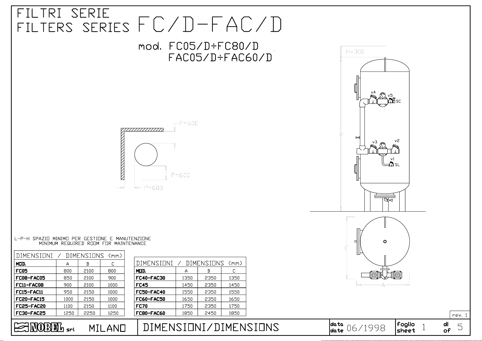
DRAWING 1: dimensions
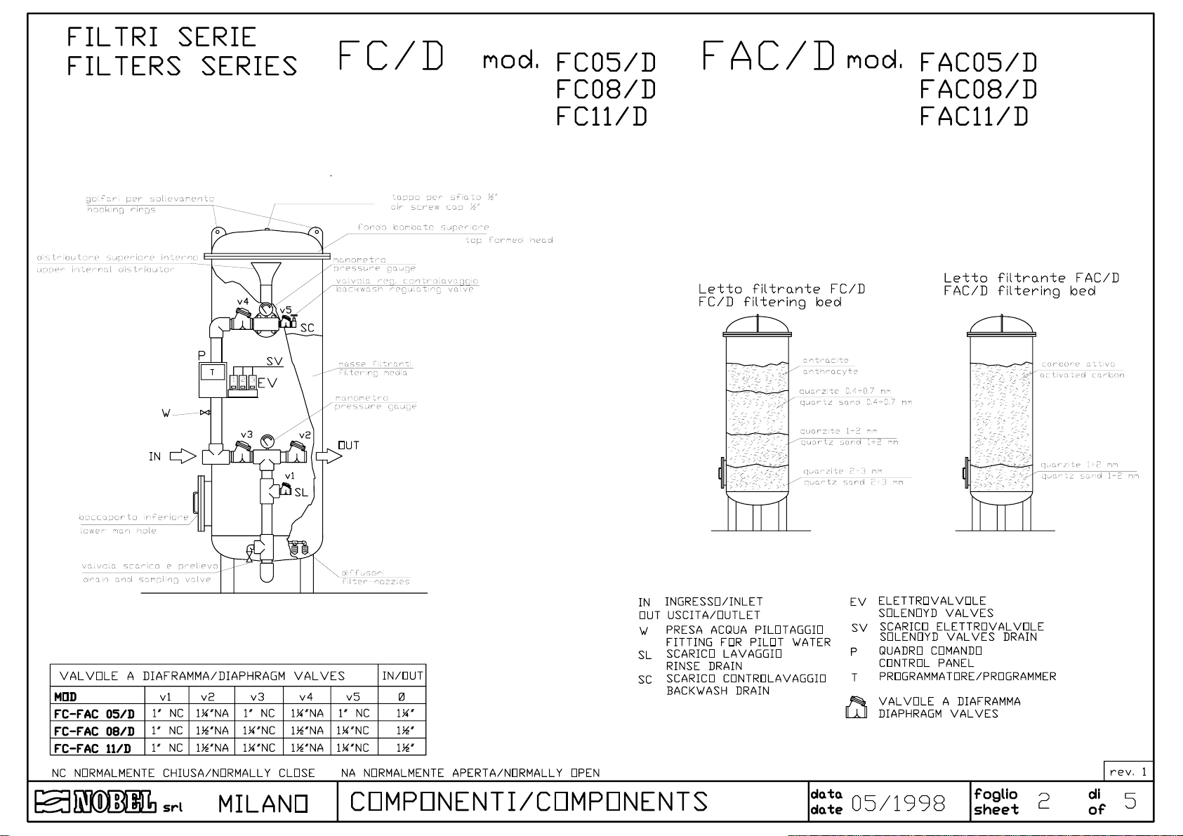
DRAWING 2: components models FC05/D÷FC11/D, FAC05/D÷ FAC11/D
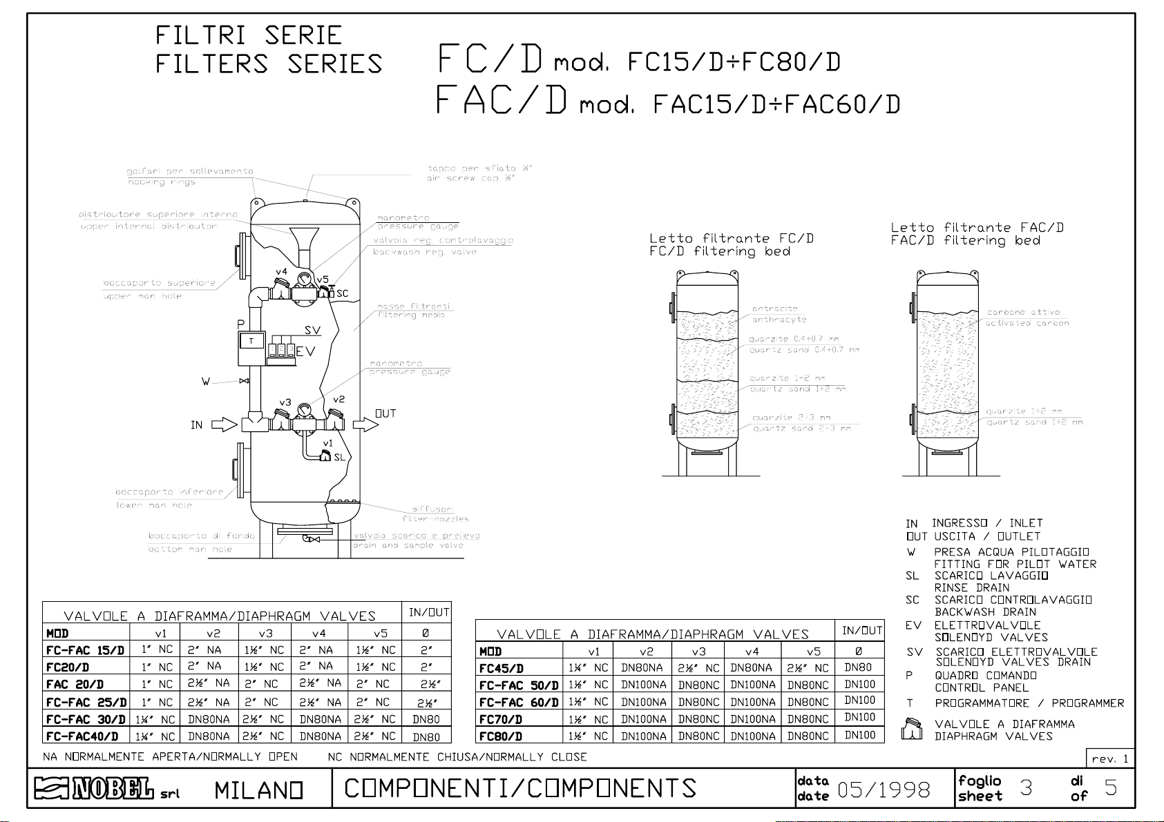
DRAWING 3: components models FC15/D÷FC80/D, FAC15/D÷FAC60/D
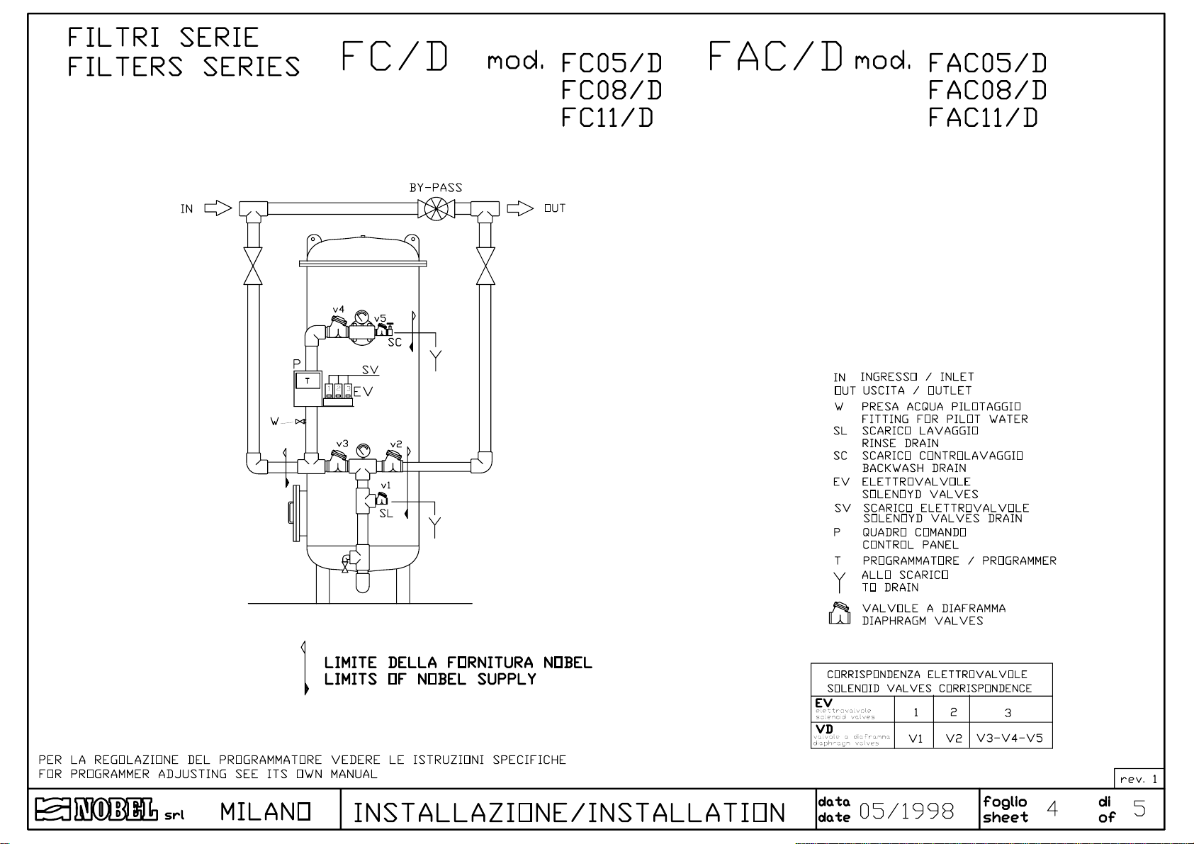
DRAWING 4: installation models FC05/D÷FC11/D, FAC05/D÷ FAC11/D
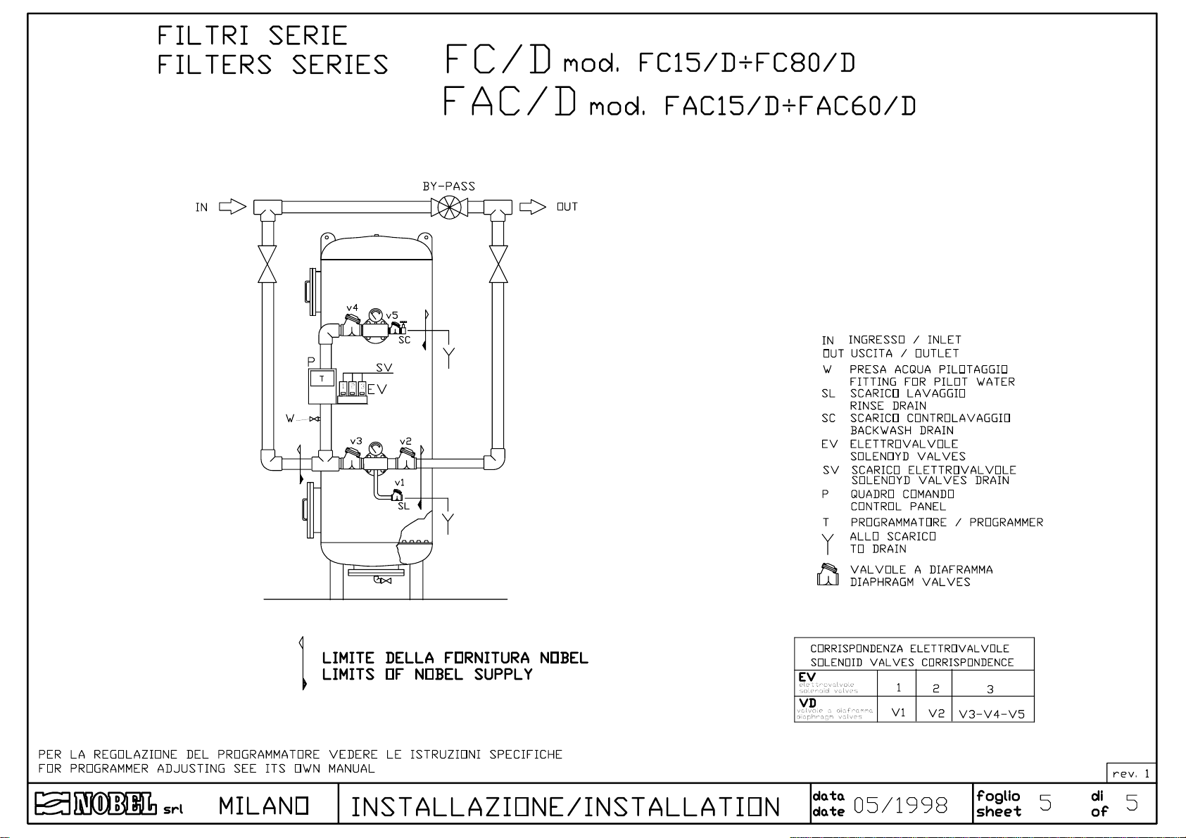
DRAWING 5: installation models FC15/D÷FC80/D, FAC15/D÷FAC60/D
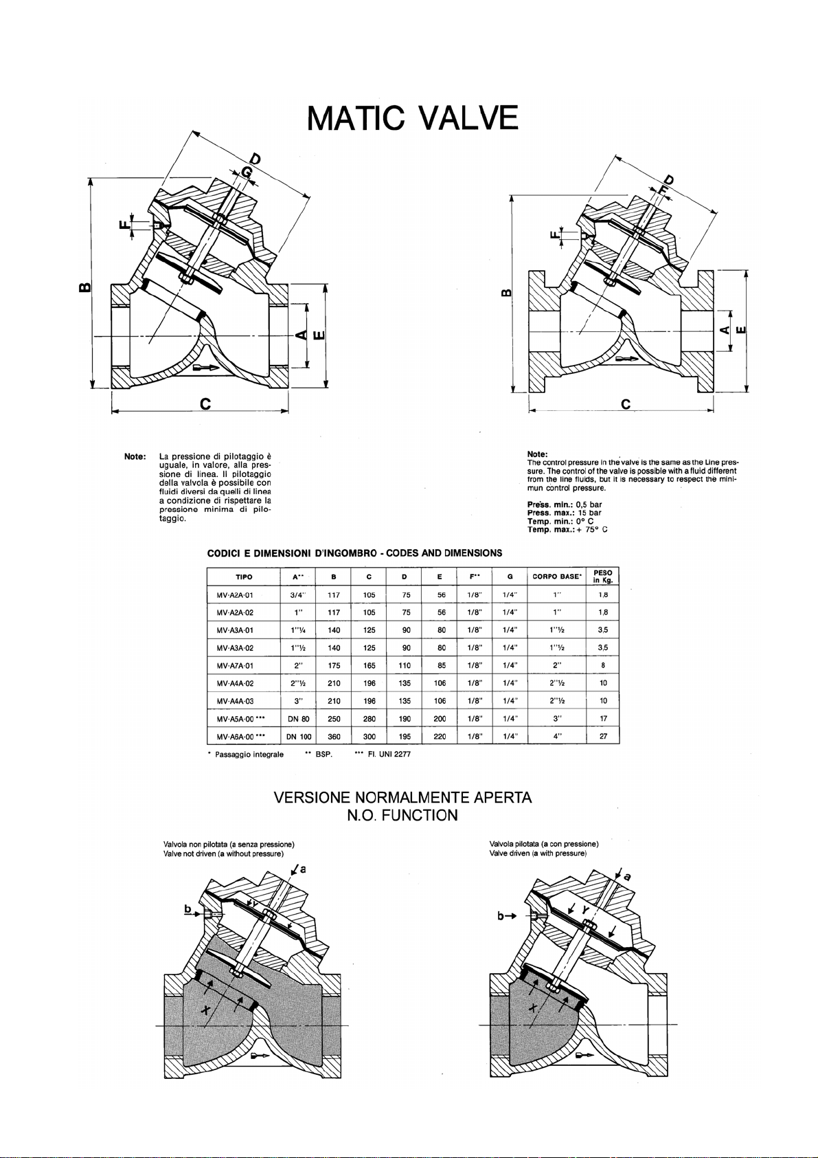
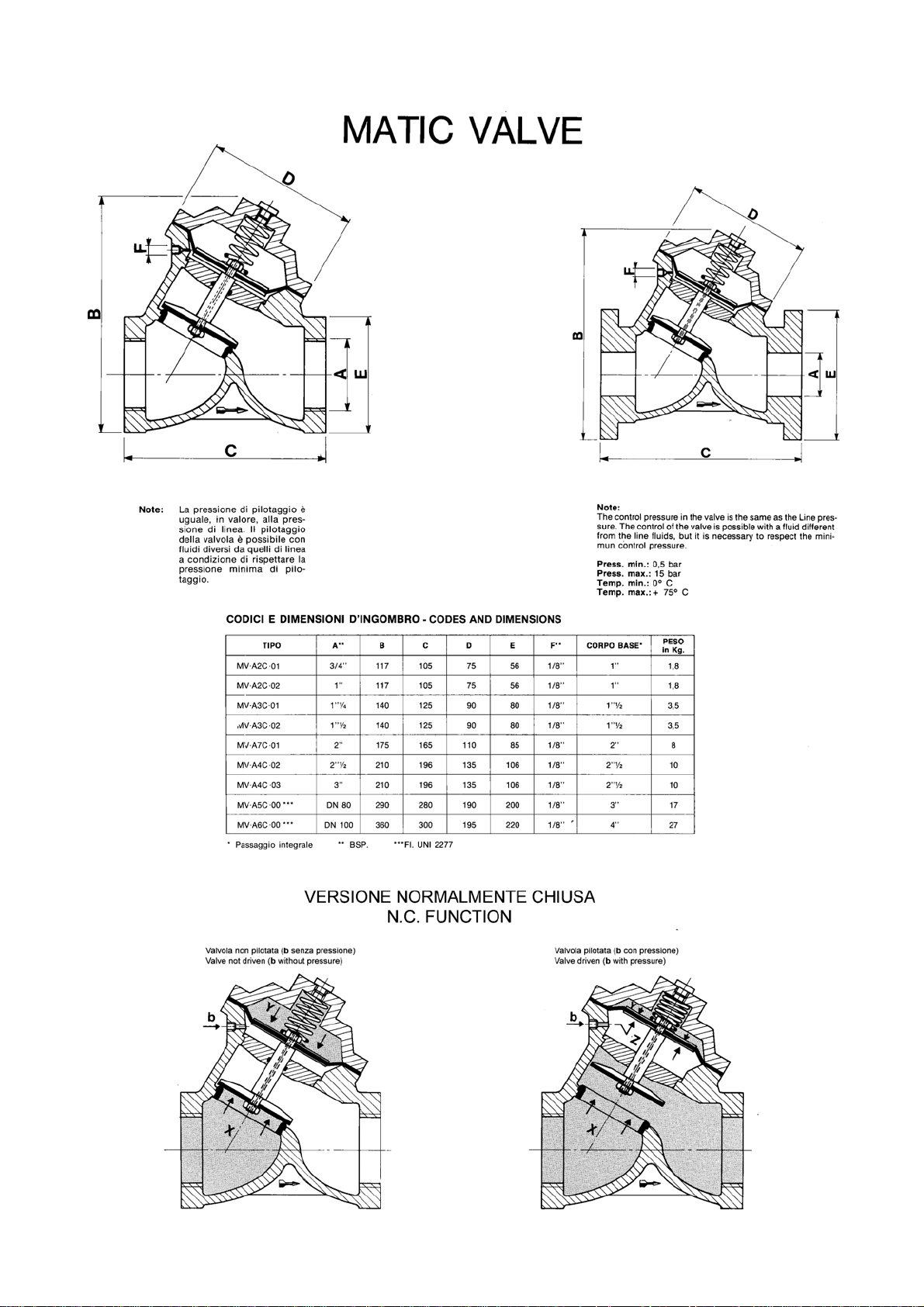
Special instructions membrane valves
Special instructions electronic programmer
FC/D - FAC/D
s.r.l.Milano - ITALY
Page 2 of 14
p11.02-v34.f fcd_mi-r1.doc
Page 3

AUTOMATIC FILTERS INSTRUCTIONS MANUAL
FC/D - FAC/D
1. Safety
1.1. General
The equipment has been designed and constructed according to D.P.R. n° 459 of 24th July
1996 (regulation for accomplishment of Norms 89/392/CEE, 91/368/CEE, 93/44/CEE and
93/68/CEE regarding the unification of States members laws in so far as machines are
concerned).
It has been designed and constructed according to European Norms UNI EN 292-1, UNI EN
292-2, UNI EN 292-2/A1, UNI EN 983, CEI EN 60439-1, CEI EN 60 204-1.
Only authorized and skilled personnel will be allowed to carry out installation, start up as well
as routine and planned maintenance.
1.2. How to displace the unit
Particular care and attention should be put in during moving and displacing of heavy items, in
order to avoid injuries to persons or damage properties. The heavy parts must be lifted and
displaced always hooking and lifting them by the points shown on the drawings (see fig. 1) and
using only suitable ropes, hooks and/or chains, according to the weight (see weight table § 3.5
page 6).
1.3. Hydraulics
All operations must be performed by and/or under direct supervision of skilled and authorized
operators, using proper tools and personal protection devices if required (CE marked).
Before any operation of taking out pipes or part of hydraulic system, it is required to release
the pressure inside and empty the part of the system.
1.4. Electrical
Before starting any operation on electrical devices, be sure that main power supply is OFF.
All operations must be performed by skilled and authorized operators.
In case of liquid leakage, switch off the main power supply before operate. Before the
switching ON, be sure all the parts of the system are perfectly dry. Check that the available
electrical power is correct, (see § 3.2 page 5) before connection. Do not make preliminary wiring
connections.
1.5. How to store and delivery
closed rooms
•
open space
•
transport
•
= ºC
5÷45 41÷113 5÷95%
5÷45 41÷113 5÷95%
5÷45 41÷113 5÷95%
= ºF humidity rel. notes
without condensate
without condensate
without condensate
protect from sun-light and rain.
protect from sun-light and rain.
s.r.l.Milano - ITALY
Page 3 of 14
p11.02-v34.f fcd_mi-r1.doc
Page 4

2. Principles of working
AUTOMATIC FILTERS INSTRUCTIONS MANUAL
FC/D - FAC/D
FC/D
and
FAC/D
series filters are used for water treatment for residential and industrial
applications as well. All the materials are food grade and approved for drinking water.
2.1. Quartz-sand filters FC/D
The filtration through a sand media is a mechanical process that allows to remove
suspended solids (even of small dimensions) from water.
The slower is the linear flow (speed of water trough the filtering bed), the better is the
filtration action.
During the process, as the filtering bed traps the suspended particles, as filtration action
increases, since the trapped solids works the same way of a filtering bed!
But it also increases the resistance of the filtering bed against the water flow; so the pressure
drop between inlet and outlet increases as well.
The maximum allowed pressure drop is 1 bar (100 kPa), after that it is required to backwash
the filtering bed.
The purpose of the backwashing is to re-built the filtering bed efficiency, by removing the
solids trapped during service; it is featured by a counter-flow of water through the filtering bed.
The working of the system is controlled by an automatic programmer, allowing to schedule
the day and the hour of the regeneration (backwashing).
For the best working of the filter, the backwashing should be featured before the pressure
drop reaches the threshold level (1 bar - 100 kPa). According to that, it is suggested to schedule
the regeneration according to a pressure drop of 0.6÷0.7 bar (60÷70 kPa).
During regeneration the water supplying is completely inhibited by means of a membrane
valve mounted on the outlet line.
2.2. Activated-carbon filters FAC/D
Filtration through a bed of activated carbon is the process that allows to remove organic
matters and chlorine from water.
The lower is the flow rate, the better is the filtration action.
FAC/D
activated-carbon used as de-chlorination (chlorine removal) is very long; it works as chemical
reduction of chlorine to chloride ion.
Activated carbon action is not selective in removing the substances contained in water and
crossing the filtering bed: hence, it removes also the organics the water contains, if any.
Therefore, it could happen that the filtering bed is exhausted or clogged by the trapping of
substances contained in water, even if the purpose of treatment was not the removal of these
substances, but just the de-chlorination.
Furthermore, it could happen that the filtering bed releases some of the substances
previously trapped in higher concentration than before.
Since it is quite impossible to forecast the exhaustion of the activated carbon bed, or to
monitor the exhaustion itself, with current instrumentation, the utilization of an activated carbon
filter must be strictly avoided without adequate pre-treatments, like quartz-sand filtration,
chlorination, etc.
series filters are designed and sized for chlorine removal. The expected life of
s.r.l.Milano - ITALY
Page 4 of 14
p11.02-v34.f fcd_mi-r1.doc
Page 5
AUTOMATIC FILTERS INSTRUCTIONS MANUAL
FC/D - FAC/D
Whether raw water contains organics and/or is biologically polluted,
CANNOT
be used without written authorization by NOBEL Technical Department.
FAC/D
series filters
The activated-carbon bed also works as a mechanic filter same way of quartz-sand bed.
Although this working should be avoided, it can happen that the pressure drop of activatedcarbon bed reaches a value of 1 bar (100 kPa); in this case the backwashing of the filtering bed
is required.
The equipment allows to schedule the days (how often) and time of day for the regeneration,
same way of quartz-sand filters, as above explained.
It is recommended to run the regeneration only when it is strictly required: the backwashing
causes the mixing of the bed and could displace the higher layers of activated carbon (most
polluted) from the top to the bottom of the column.
During regeneration the water supplying is completely inhibited by means of a membrane
valve mounted on the outlet line.
3. Technical characteristics
3.1. Assumed raw water characteristics
water temperature (min÷max)
•
water pressure (min÷max)
•
ºC (ºF) 5÷40 (41÷104)
bar (kPa) 1.5÷8.0 (150÷800)
3.2. Technical characteristics (general)
power supply
•
regeneration time
•
p min/max
• ∆
V ph/Hz W 230 1/50 50
min. 20÷30
bar (kPa) 0.2÷1.0 (20÷100)
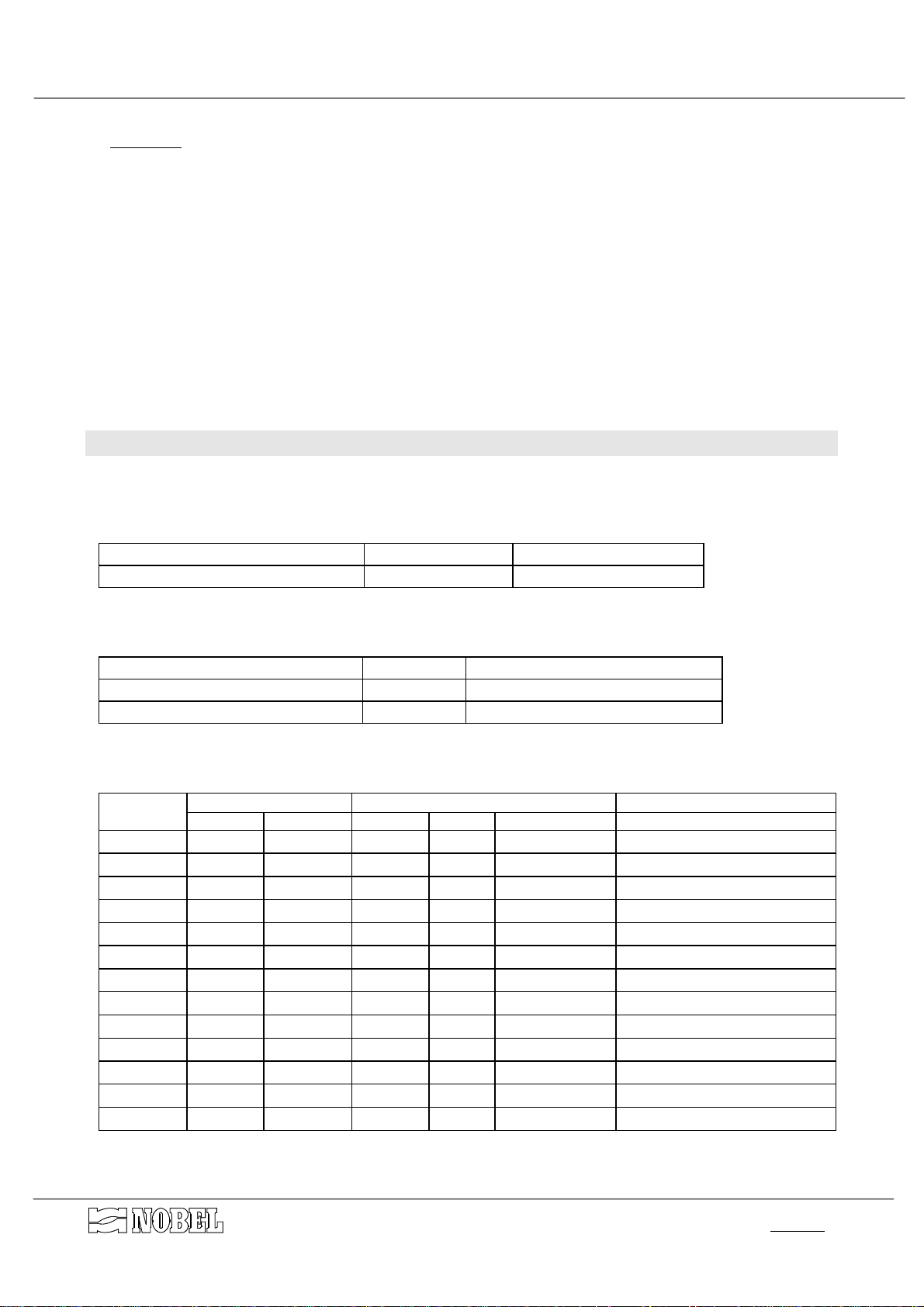
3.3. Characteristics for each model
MODEL
FC05/D
FC08/D
FC11/D
FC15/D
FC20/D
FC25/D
FC30/D
FC40/D
FC45/D
FC50/D
FC60/D
FC70/D
FC80/D
connections
IN/OUT drain
1¼" 1" 3.2 6.5 4.8 1600
1½" 1¼" 4.0 8.0 6.0 2000
1½" 1¼" 5.7 11.0 8.5 2850
2" 1½" 7.8 15.0 11.0 3900
2" 1½" 10.0 20.0 15.0 5000
2½" 2" 13.0 26.0 20.0 6500
DN80 2½" 16.0 32.0 24.0 8000
DN80 2½" 20.0 40.0 30.0 10000
DN80 2½" 23.0 46.0 35.0 11500
DN100 DN80 27.0 53.0 40.0 13500
DN100 DN80 31.0 62.0 46.0 15500
DN100 DN80 35.0 70.0 53.0 17500
DN100 DN80 40.0 80.0 60.0 20000
operating max
flow m³/h
backwash
backwashing water consumption
liters
s.r.l.Milano - ITALY
Page 5 of 14
p11.02-v34.f fcd_mi-r1.doc
Page 6
AUTOMATIC FILTERS INSTRUCTIONS MANUAL
FC/D - FAC/D
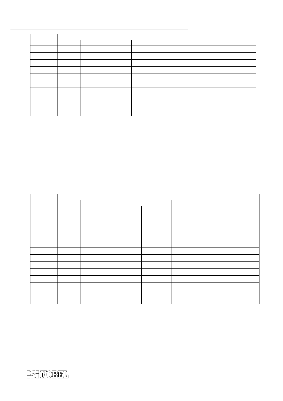
MODEL
FAC05/D
FAC08/D
FAC11/D
FAC15/D
FAC20/D
FAC25/D
FAC30/D
FAC40/D
FAC50/D
FAC60/D
connections
IN/OUT drain
1¼" 1" 5.0 5.0 500
1½" 1¼" 8.0 8.0 800
1½" 1¼" 11.0 11.0 1100
2" 1½" 15.0 15.0 1500
2½" 2" 20.0 20.0 2000
2½" 2" 24.0 24.0 2400
DN80 2½" 30.0 30.0 3000
DN80 2½" 40.0 40.0 4000
DN100 DN80 48.0 48.0 4800
DN100 DN80 61.0 61.0 6100
3.4. Dimensions
See DRAWING 1 dimensions
max
flow m³/h
backwash
backwashing water consumption
liters
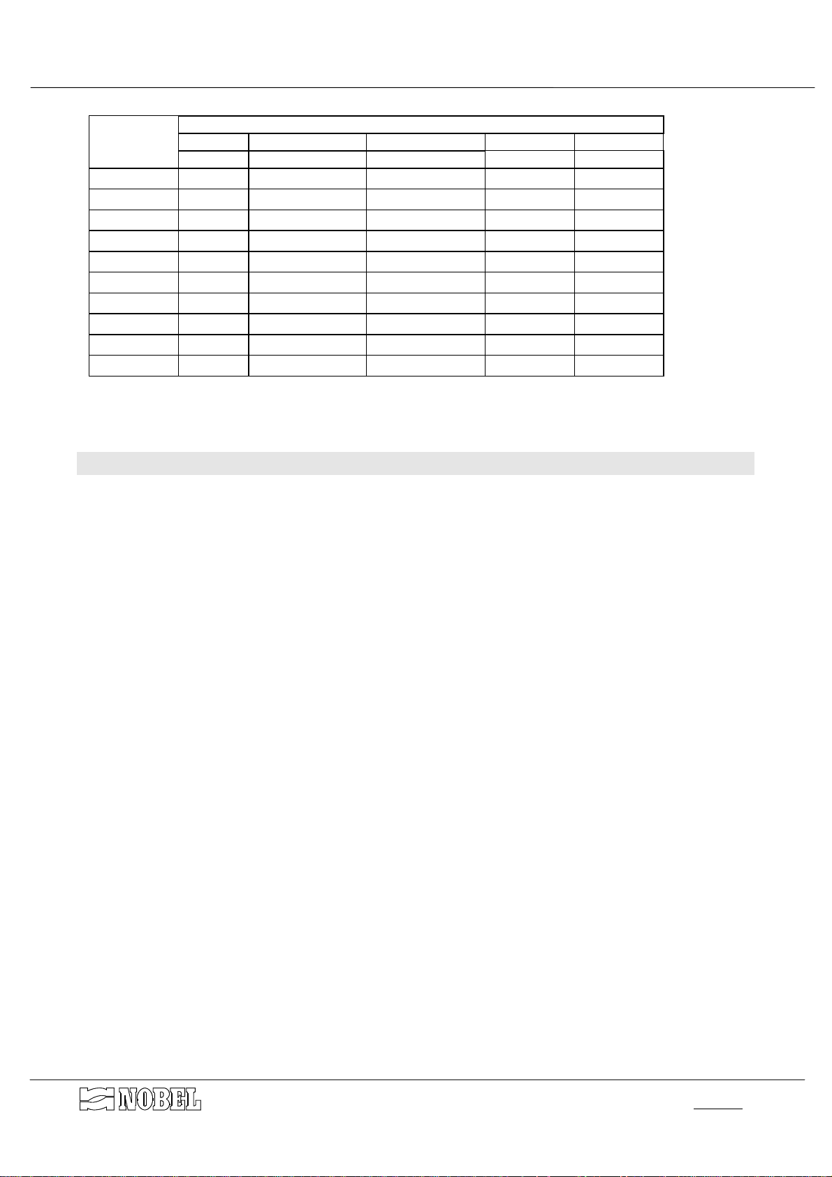
3.5. Weight
MODEL
FC05/D
FC08/D
FC11/D
FC15/D
FC20/D
FC25/D
FC30/D
FC40/D
FC45/D
FC50/D
FC60/D
FC70/D
FC80/D
WEIGHT
vessel quartz-sand kg
kg 04÷07 mm 1÷2 mm 2÷3 mm l (kg) approx. kg approx. kg
140 100 50 35 40(40) 400 600
155 120 60 50 50(50) 470 700
185 200 80 50 70(70) 620 960
300 250 100 100 100(100 900 1400
340 300 150 100 130(130 1100 1700
390 400 200 150 150(150) 1350 2100
435 500 200 200 200(200) 1650 2600
550 600 300 200 250(250) 2000 3200
610 700 350 250 300(300) 2350 3700
670 800 400 300 350(350) 2750 4500
740 900 450 350 400(400) 3100 5000
870 1100 500 400 450(450) 3500 5600
1100 1250 600 450 500(500) 4000 6400
anthracite shipping
on service
s.r.l.Milano - ITALY
Page 6 of 14
p8.04-v36.f fcd_mi-r1.doc
Page 7
MODEL
FAC05/D
FAC08/D
FAC11/D
FAC15/D
FAC20/D
FAC25/D
FAC30/D
FAC40/D
FAC50/D
FAC60/D
AUTOMATIC FILTERS INSTRUCTIONS MANUAL
WEIGHT
vessel quartz-sand 1-2 mm
kg kg l (kg) approx. kg approx. kg
155 30 200(96) 320 550
185 50 280(134) 410 750
300 50 350(168) 560 1100
340 75 500(240) 710 1300
390 100 650(312) 900 1700
435 100 800(463) 1000 1900
550 150 1000(480) 1300 2400
670 200 1350(648) 1650 3200
740 250 1600(768) 2000 3800
1100 300 2000(960) 2600 5000
activated carbon shipping
on service
FC/D - FAC/D
4. Installation
4.1. Room conditions
Room & climate conditions.
• room temperature
• humidity rel.
• sun-light
• rain, snow etc.
4.2. How to remove packaging
The vessels are shipped wrapped in a plastic foil; remove it with care before starting-up.
Keep the cards and everything contained inside the packaging.
The media filter are shipped as separated:
• in bags of 25 kg (35 liters) each or fraction anthracite
• in bags of 50 kg each or fraction quartz sand
• in bags of 25 kg (50 liters approx.) each or fraction activated carbon
5÷45ºC (41÷113ºF)
5÷95 % without condensate
protection required
protection required
s.r.l.Milano - ITALY
Page 7 of 14
p8.04-v36.f fcd_mi-r1.doc
Page 8
AUTOMATIC FILTERS INSTRUCTIONS MANUAL
FC/D - FAC/D
4.3. How to move and lift the unit
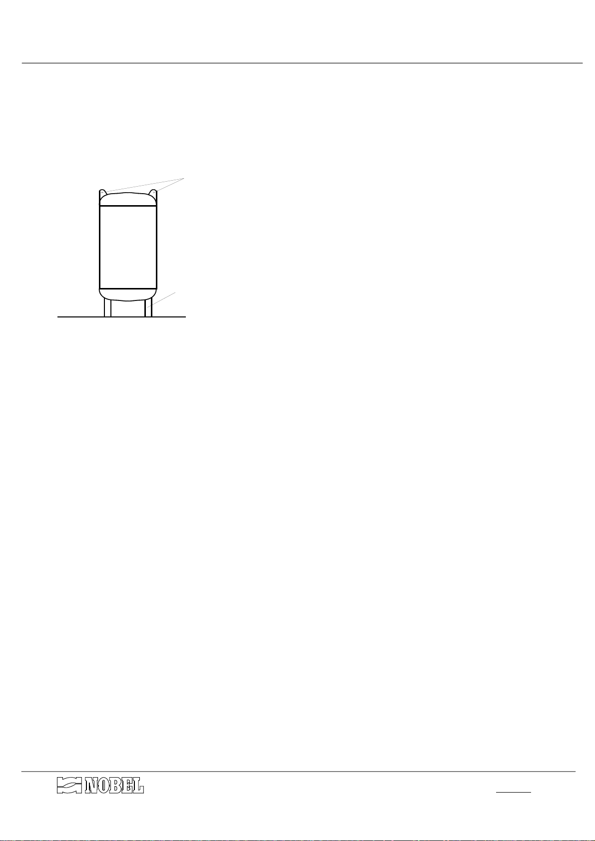
The vessels can be displaced when they are empty, hooking and lifting by the special rings
mounted on the upper part of the vessels (see fig. 1). It is recommended to use proper sized
hooks and ropes, according to the weight. It is also possible to hook and lift the vessel by the
bearing legs.
GOLFARI
CAUTION : DO NOT LIFT OR MOVE THE UNIT HOOKING OR
GAMBE DI SOSTEGNO
Figure A
CATCHING BY THE PRE-ASSEMBLED PARTS.
4.4. Placing & commissioning
Place the unit according to the available room of the site and the required room for current
maintenance and service of the equipment. See the dimensional drawing.
Place the column on a perfectly flat surface. The position shown on the installation drawing is
•
only suggested; the column can be placed in different positions, according to the inlet/outlet
connections on the valve group.
Load the supplied quartz-sand (2-3 mm size for FC/D filters, 1-2 mm size for FAC/D filters)
•
into the vessel, through the lower man-hole, until the sand covers completely the filter-
nozzles. Make a flat surface of the sand using a wooden tool, in order to avoid any damage
to the coating of the vessel. Close the man-hole tightening the nuts.
Load the rest of supplied media filter into the vessel, through the upper man-hole (or through
•
the upper head, see
components drawing
that the shipped and available quantity complies exactly with the quantity listed in the Weight
Table (§ 3.5 page 6).
Filtering media must be loaded, one after the other one, and according to the following order:
quartz sand 2÷3 mm (only for filters FC)
◊
quartz sand 1÷2 mm
◊
quartz sand 0.4÷0.7 mm (only for filters FC)
◊
anthracite (only for filters FC)
◊
activated carbon (only for filters FAC)
◊
After completed the loading, close the upper man-hole (or upper head)
•
Fix the group with membrane valves to the column (if separately shipped, see installation
•
drawing)
). The media filter are shipped separately; check
s.r.l.Milano - ITALY
Page 8 of 14
p11.02-v34.f fcd_mi-r1.doc
Page 9
AUTOMATIC FILTERS INSTRUCTIONS MANUAL
FC/D - FAC/D
4.5. Hydraulic connections
In order to avoid shut-off during maintenance operations, an emergency by-pass line
should be provided
Complete the line from inlet fittings to the raw water line.
•
Complete the line from outlet fittings (valve V2) to the treated water line.
•
Connect the drain valves (V1 and V5) to a floor drain. The gate valve mounted downstream
•
of the valve V5 will be used to adjust the backwash flow rate.
A common flexible pipe made in plastic or rubber can be used for the drain line; its diameter
must be of at least one size larger of the one mentioned on “CHARACTERISTICS FOR
EACH MODEL” table.
It is suggested the drain line could be inspected in order to check quantity and quality of
drain water, as well as any leakage of media filter from the unit.
Connect the inlet air fitting, placed on the base manifold of the solenoyd valves, to a
•
compressed air-mains, complete with pressure reducer, dehumidifier filter and shut-off valve.
The air pressure must be kept at value equal or higher of the pressure of water to be treated,
with max value of 8.0 bar.
Whether water is used to pilot the valves, the inlet fitting of the base manifold of the solenoyd
valves must be connected to the pilot water fitting (¼"), pre-arranged on the inlet manifold of
the column; run to the drain a pipe from the drain fitting (¼") of the base manifold of the
solenoyd valves.
Complete the line between the outlet fitting of each solenoyd valve to the correspondent
•
membrane valve:
SOLENOYD VALVE MEMBRANE VALVES
EV no. TYPE no. TYPE
1 NC V1 NC
2 NC V2 NA
3 NC V3-V4-V5 NC-NA-NC
All the solenoyd valves can be hand-driven by the lever placed at the base of each of them; the
turning of the lever simulate the action of the coil. Then, for valves NC type, the valve is closed
when the lever is on parallel to the base; it is opened when the lever is on perpendicular to the
base itself.
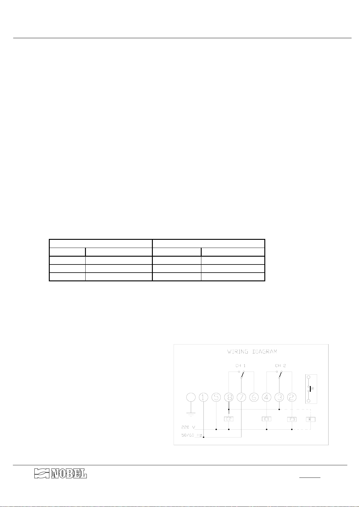
4.6. Electrical wiring connections
Connect the power cable of the
•
programmer to a power socket
check that the available power is
correct as listed in technical
characteristics (see § 3.2 page 5).
The relais R, available upon request,
•
allows to have a free voltage contact
for remote segnalation of running
regeneration; the wiring connection
must be done directly on the clamps
of NO contact on the relais itself.
s.r.l.Milano - ITALY
Page 9 of 14
p11.02-v34.f fcd_mi-r1.doc
Page 10
AUTOMATIC FILTERS INSTRUCTIONS MANUAL
FC/D - FAC/D
5. End cycle and regeneration
5.1. End cycle
The adjustment of the end cycle depends on the quantity of suspended solids the water
contains.
Take note of the parameters to be taken in consideration, as below listed, since a correct
adjustment can be made only checking the real operating conditions.
The end of a cycle is reached when the pressure drop across the filter is approx. 0.8÷1.0 bar
(80÷100 kPa). After checked after how long time the max allowable pressure drop is reached, it
is possible to adjust the time schedule of the regeneration definitely.
The filters are equipped with an electronic time programmer that allows to schedule the
automatic regeneration: it starts at selected time and day (24 h, 7 days).
5.2. Regeneration
The regeneration is automatically controlled; it can also be started manually, at any time.
The manual start of a regeneration can be made by a proper sequence of pushing the
buttons 1 and 2 placed on the programmer, in order to act the relays of the channels 1 and 2.
During the operation, the power must be ON.
When the regeneration, manually started, is completed, the unit will go on to work according
to the pre-set schedule.
The regeneration can also run in case of power failure, by hand-driving the lever of the pilot
solenoyd valves: the solenoyd valve is closed when the lever is on parallel to the base and it is
open when it is on perpendicular to the base itself. Naturally, the compressed air supplying (air
controlled valves) or pilot water supplying (water controlled valves) must be assured.
The correspondent membrane valves (controlled by the pilot solenoyd ones), if NC type is
open when the solenoyd valve is open, and viceversa if the membrane valve is NO type.
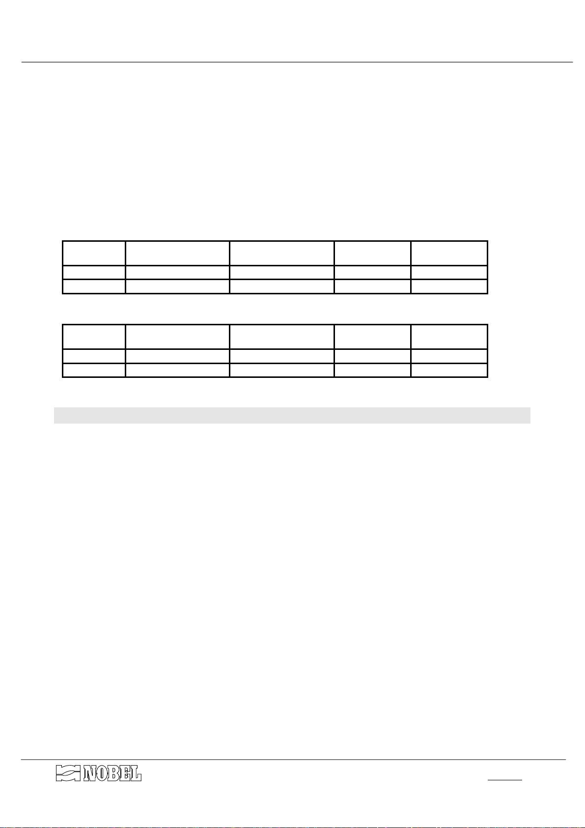
PHASE SOLENOYD VALVES
OPEN VALVES
EXCITED (=OPEN)
SERVICE // V2 - V4
BACKWASHING E2 - E3 V3 - V5
RINSE E1 - E2 V1 - V4
The regeneration phases run one after another, as follows :
1.
Backwash :
during this phase, the water flushes from the bottom to the top of the column,
lifting the filtering media and releasing the solids trapped on its surface during the service.
The backwashing water flows to drain from the top of the column. This is the only phase,
during which the water crosses through the column from the bottom to the top.
2.
Rinse :
it is the phase during which the filtering media are rinsed; at the end of this phase
the column is ready to start again a new service cycle.
NOTE: During regeneration the water supplying is completely inhibited by means of a
membrane valve mounted on the outlet line.
s.r.l.Milano - ITALY
Page 10 of 14
p11.02-v34.f fcd_mi-r1.doc
Page 11
AUTOMATIC FILTERS INSTRUCTIONS MANUAL
FC/D - FAC/D
5.3. How to set the time of regeneration
The electronic programmer keep in memory the program by mean of an EEPROM; the time
of the day is memorized even in case of power failure (internal not-rechargeable buffer battery,
charge life max 5 years without power).
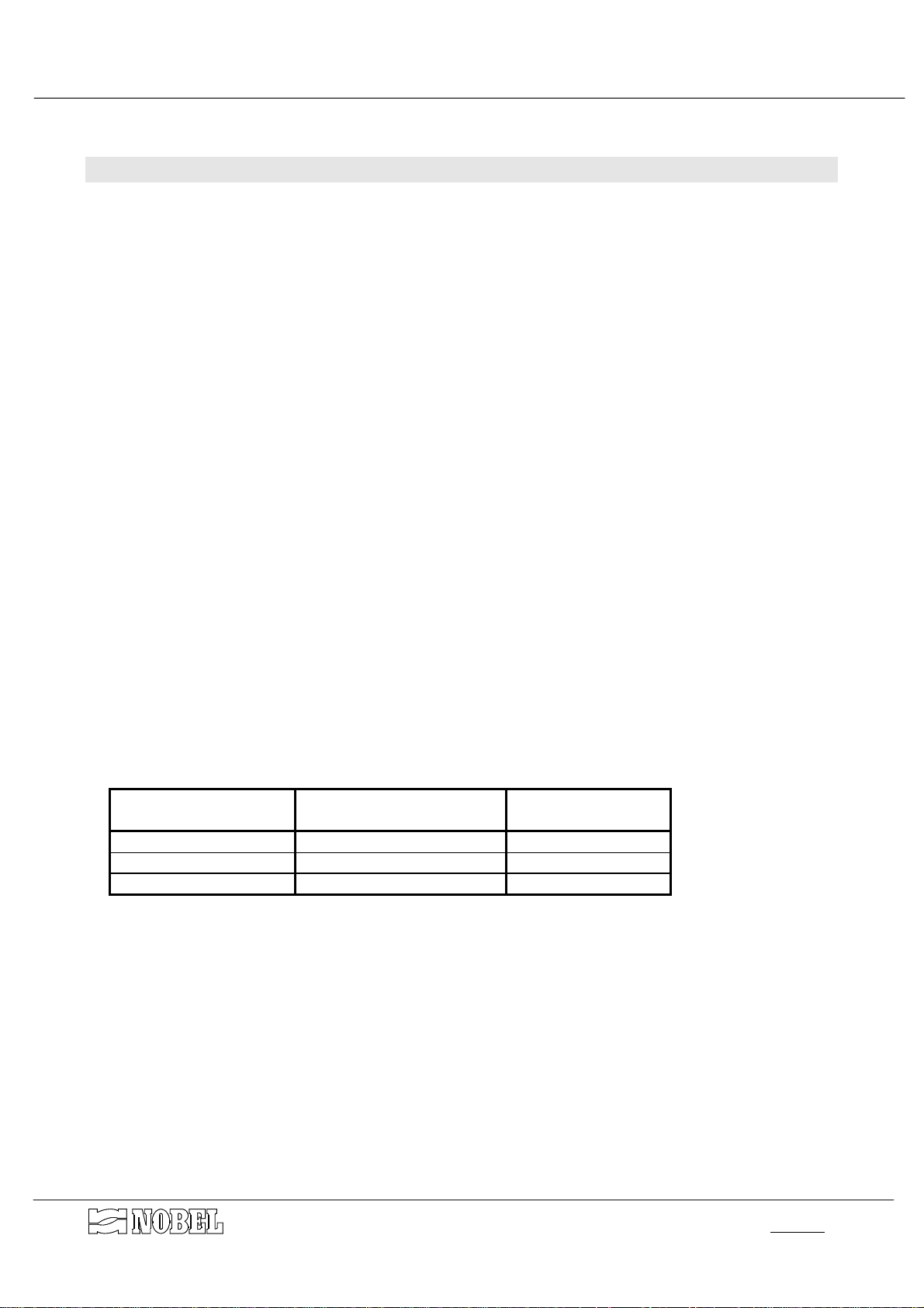
The setting or modification of the factory set values, shown on table below, is very easy. Just
take note that the start of backwashing phase is controlled by the exciting of channel 1, the
starting of the rinse phase by the exciting of channel 2, the end of rinse phase (therefore the
end of regeneration) by the elapsed time pre-set for channel 1.
For any informations concerning how to operate and modify, see attached special
instructions of the programmer.
FACTORY SET FOR FC FILTERS
start of backwash end of backwash
channel 1 ON 23.00
channel 2
FACTORY SET FOR FAC FILTERS
start of backwash end of backwash
channel 1 ON 23.00
channel 2
(regeneration once a day)
end of rinse at rest position
start of rinse
ON 23.20
OFF 23.25
(regeneration once a week)
end of rinse at rest position
start of rinse
ON 23.10
OFF 23.15
of CH2
OFF 23.30
of CH2
OFF 23.30
6. Starting-up
The starting-up of the unit consists of running a first regeneration cycle, during which the
filtering media column will be filled of water, all automatic features will be checked and the unit
will be prepared to start the service.
At the beginning, it is suggested to operate manually, hand-driven the valves, as above
explained at the § "Regeneration". This way will allow to stop, to run for longer time or to repeat
each phase as desired.
To start-up the unit, proceed as follows :
DISCONNECT ELECTRIC POWER
•
Open the by-pass and inlet valves, keeping the outlet one shut.
•
close the gate valve along the backwash drain line
•
hand-drive the solenoyd valves E3 to open the backwashing membrane valves
•
open slowly and gradually the gate valve on backwash drain line. The water will enter inside
•
the vessel from the bottom and, during filling, will expel the air inside it.
when only water will come out from the drain, adjust the drain valve in order that the flow rate
•
will be the highest allowable without any leakage of media filter through the drain line; when
the proper flow rate of backwash has been stated, adjust the gate valve definitely. The
backwashing phase must run until all the water coming out the drain is perfectly clear.
Hand-drive the solenoyd valves E3 to close the backwashing membrane valves.
•
Hand-drive the solenoyd valve E1 to open the membrane valve V1 (RINSE); the rinse phase
•
must run until all the water coming out the drain is perfectly clear.
Hand-drive the solenoyd valves E1 to close the valve V1 and to conclude the regeneration.
•
Switch ON the control panel.
•
Open the outlet valve and close the by-pass valve.
•
Starting now the unit is on service and feeds treated water.
s.r.l.Milano - ITALY
Page 11 of 14
p11.02-v34.f fcd_mi-r1.doc
Page 12

AUTOMATIC FILTERS INSTRUCTIONS MANUAL
7. Service & maintenance
Automatic filters are equipment designed to treat raw water supplied from
municipalities or from well.
ANY OTHER APPLICATIONS OF THE EQUIPMENT DIFFERENT THAN THE MENTIONED
ONES IS MADE UNDER THE ONLY RESPONSIBILITY OF THE USER.
The correct handling of the equipment requires :
check that the air and/or water pressure are within the stated values.
•
Not any further special maintenance operations are required.
There is not any consumption material to be currently replaced.
The average life of the filter-bed is approx. 5÷8 years, according to the quality of raw water
and how often regeneration is featured.
FC/D - FAC/D
7.1. Disposal
In case of disposal of the unit or parts of it, it must be made according to local laws
concerning the waste of the materials.
Concerning media filter, they are natural products that, at origin state, can be disposed of as
natural products. Whether the activated carbon had trapped special and particular substances,
the carbon will be classified as same class of the trapped substances.
To dispose of them it should be required to identify the class of this waste, by a detailed
analysis.
s.r.l.Milano - ITALY
Page 12 of 14
p11.02-v34.f fcd_mi-r1.doc
Page 13
8. Main components
AUTOMATIC FILTERS INSTRUCTIONS MANUAL
FC/D - FAC/D
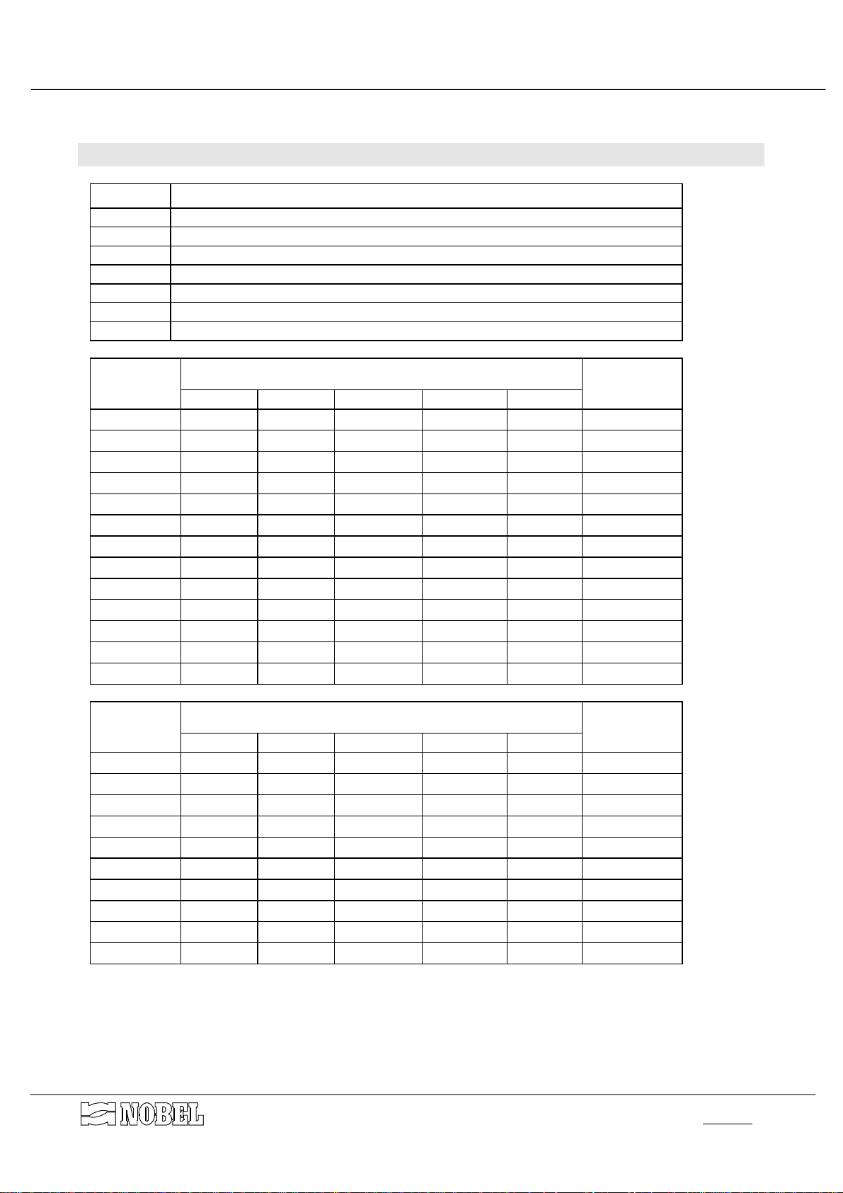
Quantity
1 vessel in coated carbon steel (see table DIMENSIONS)
1 internal water distribution system (see following table)
# filtering media (see table WEIGHT)
5 membrane valves made in cast-iron (see following table)
3 pilot solenoyd valves TYPE_______
1 electronic programmer type VEMER LOGIK DW2
# galvanized steel fittings several size
MODEL
FC05/D
FC08/D
FC11/D
FC15/D
FC20/D
FC25/D
FC30/D
FC40/D
FC45/D
FC50/D
FC60/D
FC70/D
FC80/D
MODEL
FAC05/D
FAC08/D
FAC11/D
FAC15/D
FAC20/D
FAC25/D
FAC30/D
FAC40/D
FAC50/D
FAC60/D
DESCRIPTION
membrane valves
V1 V2 V3 V4 V5 number/type
1"NC 1¼"NA 1"NC 1¼"NA 1"NC 12 short
1"NC 1½"NA 1¼"NC 1½"NA 1¼"NC 12 short
1"NC 1½"NA 1¼"NC 1½"NA 1¼"NC 18 short
1"NC 2"NA 1½"NC 2"NA 1½"NC 30 plate
1"NC 2"NA 1½"NC 2"NA 1½"NC 36 plate
1"NC 2½"NA 2"NC 2½"NA 2"NC 42 plate
1¼"NC DN80NA 2½"NC DN80NA 2½"NC 56 plate
1¼"NC DN80NA 2½"NC DN80NA 2½"NC 68 plate
1¼"NC DN80NA 2½"NC DN80NA 2½"NC 84 plate
1½"NC DN100NA DN80NC DN100NA DN80NC 87 plate
1½"NC DN100NA DN80NC DN100NA DN80NC 104 plate
1½"NC DN100NA DN80NC DN100NA DN80NC 118 plate
1½"NC DN100NA DN80NC DN100NA DN80NC 142 plate
membrane valves
V1 V2 V3 V4 V5 number/type
1"NC 1¼"NA 1"NC 1¼"NA 1"NC 12 short
1"NC 1½"NA 1¼"NC 1½"NA 1¼"NC 18 short
1"NC 1½"NA 1¼"NC 1½"NA 1¼"NC 30 plate
1"NC 2"NA 1½"NC 2"NA 1½"NC 36 plate
1"NC 2½"NA 2"NC 2½"NA 2"NC 42 plate
1"NC 2½"NA 2"NC 2½"NA 2"NC 56 plate
1¼"NC DN80NA 2½"NC DN80NA 2½"NC 68 plate
1¼"NC DN80NA 2½"NC DN80NA 2½"NC 87 plate
1½"NC DN100NA DN80NC DN100NA DN80NC 104 plate
1½"NC DN100NA DN80NC DN100NA DN80NC 142 plate
distribution
system
distribution
system
s.r.l.Milano - ITALY
Page 13 of 14
p11.02-v34.f fcd_mi-r1.doc
Page 14
AUTOMATIC FILTERS INSTRUCTIONS MANUAL
FC/D - FAC/D
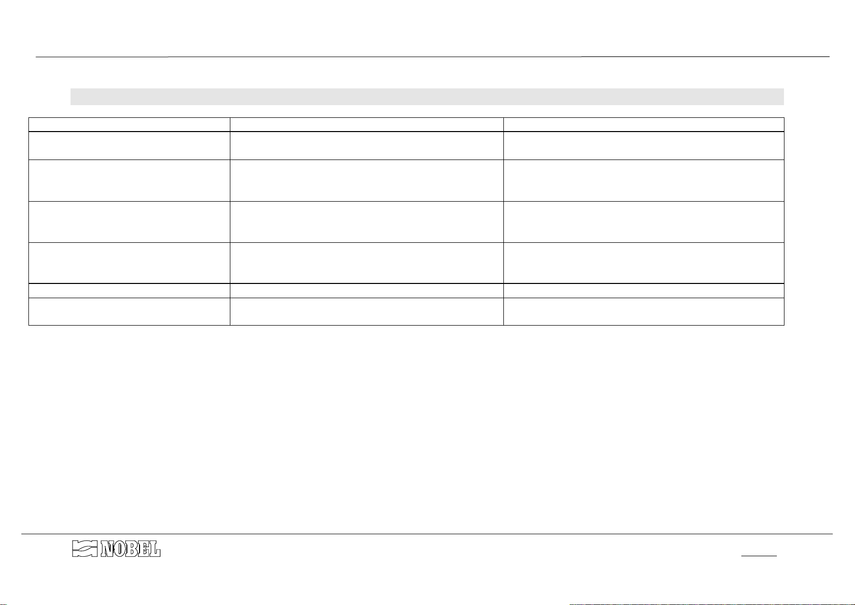
9. Trouble shooting guide
PROBLEM CAUSE HOW TO SOLVE
• The electronic programmer does not
switch ON.
• electrical power is disconnected
• the programmer is defected
• The regeneration does not run • electrical power is disconnected
• the programmer is not correctly adjusted
• the programmer is defected
• Regeneration is electrically started
but it does not run hydraulically
• there is not supplying of pilot fluid (air or water)
• one or more solenoyd valves are defected
• There is a leakage of water to drain
during service
• one or both membrane valves no. 1 and 5 do not
close properly.
• The unit does not feed water • the membrane valve no. 2 does not open • check the proper working of the pilot solenoyd valve
• There is a leakage of filtering media
to the drain or to the outlet line
• one nozzle of distribution system is damaged or
broken
• connect electrical power
• replace the programmer
• connect electrical power
• adjust correctly the programmer
• replace the programmer
• connect properly the supplying of pilot water or
compressed air
• replace the defected solenoyd valves
• check the proper working of the pilot solenoyd valves
• check and clean the seat of the plate of the
membrane valve
• replace the nozzle
s.r.l.Milano - ITALY Page 14 of 14
p11.02-v34.f fcd_mi-r1.doc
Page 15
Page 16
Page 17
Page 18
Page 19
Page 20
Page 21
 Loading...