

Nobel RO 406 /E, RO 409 /E, RO 404 /E, RO 404 /EL, RO 406 /EL Maintenance Manual
...
REVERSE OSMOSIS
RO 404 /E - RO 406 /E - RO 409 /E - RO 412 /E
RO 404 /EL - RO 406 /EL - RO 409 /EL - RO 412 /EL
INSTRUCTIONS MANUAL
INSTRUCTIONS FOR INSTALLATION OPERATION & MAINTENANCE
WARNING!
The equipment must be used only for the utilization for which they have been
designed, as shown in the technical documentation.
Read carefully this leaflet until the end before starting any operation.
Proceed strictly according to all directions included in this manual.
Reverse osmosis systems models RO/E are designed to treat raw water supplied from
municipalities or from well.
ANY OTHER APPLICATIONS OF THE EQUIPMENT DIFFERENT THAN THE MENTIONED
ONES IS MADE UNDER THE ONLY RESPONSIBILITY OF THE USER.
For any assistance concerning the installations, maintenance or utilization of the equipment
apply the NOBEL Service Center closest to you or directly :
NOBEL S.r.l. via Monfalcone 8 - 20132 Milano - Italy
tel. +39 02 2827968 fax +39 02 2610839
ro4e_mi-r10.doc
rev. 10

REVERSE OSMOSIS SYSTEMS RO 4... /E /EL - INSTRUCTIONS MANUAL
INDEX
1. Safety........................................................................................................................................4
1.1. General ...............................................................................................................................4
1.2. How to displace the unit......................................................................................................4
1.3. Hydraulics ...........................................................................................................................4
1.4. Electrical..............................................................................................................................4
1.5. Directions for storage, delivery, installation.........................................................................4
2. Principles of working.................................................................................................................5
3. Technical characteristics ..........................................................................................................5
3.1. Assumed raw water characteristics.....................................................................................5
3.2. Technical characteristics series standard (RO...E) .............................................................6
3.3. Technical characteristics series low energy (RO...EL)........................................................6
4. Installation ................................................................................................................................7
4.1. Room conditions .................................................................................................................7
4.2. How to remove packaging...................................................................................................7
4.3. How to move and lift the unit ...............................................................................................7
4.4. Placing ................................................................................................................................7
4.5. Hydraulics connections .......................................................................................................8
4.6. Electrical wiring connections ...............................................................................................8
5. Control panel ............................................................................................................................9
5.1. Commands and visualizations ............................................................................................9
5.2. Logical programmer ..........................................................................................................11
5.2.1. Reports on the display of the programmer ..............................................................11
5.2.2. How to set current time and day ...............................................................................12
5.2.3. How to set times and delays.....................................................................................12
5.2.4. How to use the function buttons of the programmer.................................................13
5.3. Logic of working ................................................................................................................13
5.3.1. Levels .......................................................................................................................14
5.3.2. External enabling signals..........................................................................................15
5.3.3. Hand-driven working.................................................................................................15
5.3.4. Flushing ....................................................................................................................15
5.3.5. Conductivity ..............................................................................................................16
5.3.6. Minimum pressure ....................................................................................................16
5.3.7. Working of the pump.................................................................................................17
5.3.8. Remote alarm ...........................................................................................................17
5.3.9. Optional features (available upon request)...............................................................17
6. Starting-up and adjustments...................................................................................................18
6.1. Resuming table of the factory settings ..............................................................................19
7. Maintenance ...........................................................................................................................20
7.1. Periodical monitoring.........................................................................................................20
7.2. Non-working period ...........................................................................................................20
7.3. How to insert or replace membranes ................................................................................21
7.4. Cleaning of the membranes ..............................................................................................22
7.5. How to adjust the min pressure switch PC........................................................................23
7.6. Disposal ............................................................................................................................23
7.7. Table of chemicals for membranes cleaning.....................................................................24
8. Trouble shooting guide ...........................................................................................................25
s.r.l.Milano - ITALY Page 2 of 25 ro4e_mi-r10.doc - r. 10

REVERSE OSMOSIS SYSTEMS RO 4... /E /EL - INSTRUCTIONS MANUAL
Annex :
• diagram UNIT DRAWING • fitting-out table
• diagram DIMENSIONAL/WEIGHT • special instructions filters
• diagram PLACING • special instructions inlet solenoid valve
• diagram MEMBRANES WASHING • special instructions flushing solenoid valve
• diagram FRONT OF CONTROL PANEL • special instructions 3-ways valves
• wiring diagrams (4 pages) • special instructions high-pressure pump
• drawing terminal boxes • special instructions conductimeter
• NOBEL running-test certificate • special instruction flow meters
• components list •
s.r.l.Milano - ITALY Page 3 of 25 ro4e_mi-r10.doc - r. 10
REVERSE OSMOSIS SYSTEMS RO 4... /E /EL - INSTRUCTIONS MANUAL
1. Safety
1.1. General
The equipment has been designed and constructed according to D.P.R. n° 459 of 24th July
1996 (regulation for accomplishment of Norms 2006/42/CE, 91/368/CE, 93/44/CE and 93/68/CE
regarding the unification of States members laws in so far as machines are concerned).
It has been designed and constructed according to European Norms UNI EN 292-1, UNI EN
292-2, UNI EN 292-2/A1, UNI EN 418, CEI EN 60439-1,
Only authorized and skilled personnel will be allowed to carry out installation, start up as well
as routine and planned maintenance.
1.2. How to displace the unit
Particular care and attention should be put in during moving and displacing of heavy items, in
order to avoid injuries to persons or damage properties. The heavy components must be lifted
and displaced by lifting or hooking them up only by the points and facilities shown on the
attached drawings. It is strictly recommended to use only proper sized and suitable ropes,
chains or hooks (see DIMENSIONS & WEIGHT).
CEI EN 60 204-1.
1.3. Hydraulics
All operations must be performed by and/or under direct supervision of skilled and
authorized operators, using proper tools and personal protection devices if required
(CE marked), according to safety regulations for working areas. The operators must
be aware of the hazards and danger of the chemicals used in the process.
In case of leakage of chemicals and/or in case of accident (contact with skin, eyes,
etc.) follow strictly the directions mentioned on the safety bulletins of the chemicals
themselves. Before any operation of taking out pipes or part of hydraulic system, it is
required to release the pressure inside and empty the part of the system.
1.4. Electrical
Before starting any operation on electrical devices, be sure that main power supply is
OFF. All operations must be performed by skilled and authorized operators, using
proper tools and personal protection devices if required (CE marked), according to
safety regulations for working areas.
In case of liquid leakage, switch off the main power supply before operation. Before
the switching ON, be sure all the parts of the system are perfectly dry. Check that the
available electrical power is correct, as shown on technical data
Do not make preliminary wiring connections.
1.5. Directions for storage, delivery, installation
• closed rooms
• open space
• transport
• installation
t = ºC t = ºF humidity rel. notes
5÷40 41÷104 5÷95%
5÷40 41÷104 5÷95%
5÷40 41÷104 5÷95%
5÷40 41÷104 5÷95%
s.r.l.Milano - ITALY Page 4 of 25 ro4e_mi-r10.doc - r. 10
without condensate
without condensate
without condensate
without condensate
protect from sun-light and rain.
protect from sun-light and rain.
protect from sun-light and rain.
REVERSE OSMOSIS SYSTEMS RO 4... /E /EL - INSTRUCTIONS MANUAL
2. Principles of working
Osmosis is a natural phenomenon : it is the spontaneous passage of a liquid from a dilute to
a more concentrated solution across a semi-permeable membrane. The driving force of the
solution through the membrane is its osmotic pressure. Osmotic pressure is function of the
concentration of the solution or, in our cases, of the salinity of water.
Reverse Osmosis is the process in which the natural osmotic flow is reversed. Reversal is
effected by the application of pressure, greater than the osmotic pressure, to the concentrated
solution. Fresh water diffuses through the membrane (practically containing only a small
quantities of dissolved salts).
Reverse osmosis process allows the removal of approx. 90÷99 % of dissolved salts and
pollutants, if any. The real % removal depends on the kind of membrane used.
The semi-permeable membrane consists of several layers of special fibers, and can be made
of different type and design (spiral wound, hollow fibber, etc.). The word permeate indicates the
product water, while the word concentrate indicates the flow of water carried to drain, which
contains the dissolved salts removed from the permeate.
3. Technical characteristics
3.1. Assumed raw water characteristics
• silt density index (SDI)
• max TDS of raw water
¾ series standard (RO...M) ppm
¾ series low energy (RO...ML) ppm
• raw water temperature min÷max
• raw water pressure min÷max
• bacteria
• free chlorine
• iron
• silica
• total hardness: according to the pre-treatment
* max. value : according to the construction material used
ºC (°F) 10÷40 (50÷104)
bar (kPa) 2.0÷5.0 (200÷500)
nil
ppm Cl
ppm Fe
ppm SiO
2
≤ 3
≤ 5000 *
≤ 1000 *
≤ 0.1
≤ 0.1
≤ 10.0
s.r.l.Milano - ITALY Page 5 of 25 ro4e_mi-r10.doc - r. 10

REVERSE OSMOSIS SYSTEMS RO 4... /E /EL - INSTRUCTIONS MANUAL
3.2. Technical characteristics series standard (RO...E)
• TDS of treated water *
• power supply
• power
• working pressure
• max. allowable pressure
• permeate t= 15 ºC
• feed water min-max
V/ph/Hz 400/3/50
kW 3.0 4.0 7.5 7.5
bar (kPa) 16 (1600) approx
bar (kPa) 22 (2200)
l/h 1.000 ** 1.500 ** 2.250 ** 3.000 **
l/h 1.600÷3.200 2.000÷4.000 3.600÷7.200 4.800÷9.600
• dimensions
• weight on service
• vessel
kg 220 260 360 400
nº 2 on serial 2 on parallel + 1 on serial 2 on parallel
RO404 /E RO406 /E RO409 /E RO412 /E
≤ 2 % of raw water
See dimensional diagram
+ 2 on serial
• membranes ø 4”
• filtering elements
nº 4 6 9 12
nº 4 x 10" 5 x 10" 8 x 10" 7 x 20"
* the mentioned percentage is referred to TDS of treated water and of the raw one; it depends
on the chemical-physical characteristics of raw water, the recovery rate and the operating
features of the system.
** treated water quantities, (permeate), as shown, depends on the raw water temperature (feed
water) and strictly depends on its chemical-physical characteristics.
3.3. Technical characteristics series low energy (RO...EL)
• TDS of treated water *
• power supply
• power
• working pressure
• max. allowable pressure
• permeate t= 15 ºC
• feed water min-max
V/ph/Hz 400/3/50
kW 2.2 3.0 3.0 4.0
bar (kPa) 10 (1000) approx
bar (kPa) 14 (1400)
l/h 1000 ** 1500 ** 2250 ** 3000 **
l/h 1300÷2000 2000÷3000 3000÷4500 4000÷6000
• dimensions
• weight on service
• vessel
• membranes ø 4”
• filtering elements
kg 220 260 360 400
nº 2 on serial 2 on parallel + 1 on serial 2 on parallel
nº 4 6 9 12
nº 4 x 10" 5 x 10" 8 x 10" 7 x 20"
* the mentioned percentage is referred to TDS of treated water and of the raw one; it depends
on the chemical-physical characteristics of raw water, the recovery rate and the operating
features of the system.
** treated water quantities, (permeate), as shown, depends on the raw water temperature (feed
water) and strictly depends on its chemical-physical characteristics.
RO404 /EL RO406 /EL RO409 /EL RO412 /EL
≤ 5 % ingresso
See dimensional diagram
+ 2 on serial
s.r.l.Milano - ITALY Page 6 of 25 ro4e_mi-r10.doc - r. 10
REVERSE OSMOSIS SYSTEMS RO 4... /E /EL - INSTRUCTIONS MANUAL
4. Installation
4.1. Room conditions
These units do not include visible moving or specially noising parts (see also the "noise
monitor chart" attached to the special instructions of high-pressure pump). There are not any
points which reaches high temperature.
4.2. How to remove packaging
The packaging consist of a wooden crate which contains the reverse osmosis system, skidmounted.
Open the wooden crate removing, first, the cover and, then, the sides. Keep the cards and
everything contained inside the packaging.
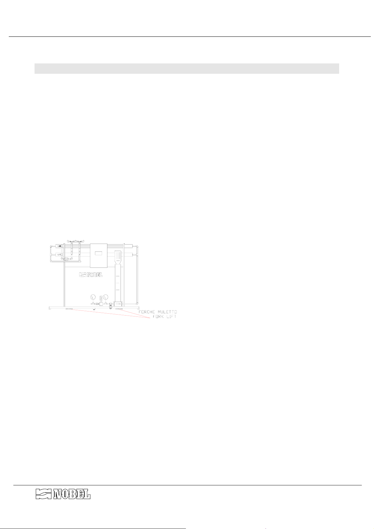
4.3. How to move and lift the unit
Some of the pipes of the plant are made in
plastic material, hence they can be easily
damaged. Do not lift and/or move the unit by
any part of the plant. Use only the hooking
rings, placed on the upper part of the skid to
lift the unit, and ropes or chain of adequate
size and dead-weight capacity. (see
DIMENSIONS/WEIGHT diagram) Fork-lift or
other suitable equipment can be used,
checking to warrant correct balance and
stability during the movement. Insert the forks
on the front of the skid as shown on sketch.
4.4. Placing
Place the unit on a perfectly flat surface.
Follow the directions of the dimensional drawing for the correct placing of the unit, according
to the dimensions of the available room and the required room for service and maintenance.
Not any anti-vibration devices is required, hence the unit can be directly placed on floor.
s.r.l.Milano - ITALY Page 7 of 25 ro4e_mi-r10.doc - r. 10

REVERSE OSMOSIS SYSTEMS RO 4... /E /EL - INSTRUCTIONS MANUAL
4.5. Hydraulics connections
see DIAGRAM OF THE SYSTEM and
DIMENSIONS/WEIGHT DIAGRAM
• Connect the raw water line (I) to the filtration unit (F), using pipes made in PVC or other
suitable materials, with size (Ø) equal or larger than the size of inlet connection (I).
• Whether the raw water contains a large quantity of suspended solids, the filters (filtration 5
µm) could be clogged very quickly; in this case a proper Nobel pre-filter with filtration of 50
µm, should be provided. According to the characteristics of raw water, the pre-treatment
could be required; apply Nobel Technical Dept. for proper suggestion.
• Run the line from the product water outlet fitting (U) to the storage tank, using pipes made
in PVC or other suitable materials, with size (Ø) equal or larger than the size of outlet
connection (U).
• Run the line from the drain fitting (S) to a floor drain of a proper size, using pipes made in
PVC or other suitable materials, with size (Ø) equal or larger than the size of concentrate
connection (S).
• The pre-arranged fittings for cleaning (R and R1) will be connected, only when required, to
the cleaning tank and/or to the drain. Indeed, it allows the recirculation (or the drain) of
permeate and concentrate during these operation.
FOR SYSTEMS ARRANGED FOR FLUSHING WITH RO PROCESSED WATER ONLY :
• Connect the intake of RO processed water for flushing to the inlet fitting (IF) using pipes
made in PVC or other suitable materials, with size (Ø) equal or larger than the size of the
fitting (IF).
THE OUTLET PRODUCT WATER LINE MUST BE COMPLETELY FREE OF
ANY SHRINKAGE - THROTTLING - SHUT OFF VALVE
4.6. Electrical wiring connections
Run the electrical wiring connections to the terminal board of the control panel (QE), as
described in the attached resuming sheets of terminal boards. All the connections between
control panel to the equipments mounted on the skid, have been already made in factory (see
WIRING DIAGRAM).
• The power supply plant must be made according to the value of voltage, frequency and
adsorption, as stated at paragraph “TECHNICAL CHARACTERISTICS”.
• The size of the wires of the electrical power conductors must be selected according to the
max allowable current intensity.
• The power supply line must be protected by an automatic differential circuit breaker, with
adequate power and according to applicable law.
• It is recommended to use suitable fittings, for the wiring connection, in order not to modify
the protection grade of the control board.
s.r.l.Milano - ITALY Page 8 of 25 ro4e_mi-r10.doc - r. 10

REVERSE OSMOSIS SYSTEMS RO 4... /E /EL - INSTRUCTIONS MANUAL
5. Control panel
The control panel QE, handled by a logical programmer, controls the automatic and/or
manual working of the whole system.
For safety sake, when the high pressure pump P is on working, the inlet solenoid valve EI is
open (except during the flushing with RO processed water, during which the solenoid valve EIF
is open), both automatic and manual working as well. Hence, in this manual, any time the
working of the high pressure pump P is mentioned, it is understood that the inlet solenoid valve
EI is open,
The starting of the pump is some seconds delayed than the opening of the solenoid valve EI.
5.1. Commands and visualizations
(see diagram FRONT OF CONTROL PANEL)
The instruments available on the control panel are :
CONDUCTIVITY-METER
the instrument continuously shows the conductivity of the treated
water (permeate).
When the conductivity of treated water overpasses the set-point value
(set-point K1), the high conductivity alarm is switched on.
LOGICAL
PROGRAMMER LOGO
the programmer that handles the logical working of the unit.
Its display shows the status of the inputs and outputs and allows to
modify the pre-set time of the used timers (see special chapter for
details).
The commands available on the front of control panel QE are :
"EMERGENCY STOP "
It is placed on the top side of the control panel; pushing the button
any working of the system is blocked. To re-start the system, turn
counter clock-wise the button, for approx. 30º.
SELECTOR "MODE"
it controls the working of the system
“AUT-RESET-MAN”
on “AUT”
on “MAN”
on “RESET”
BUTTON "FLUSHING"
The synoptical panel shows graphically the installed items; when one of them is activated,
the correspondent led is ON. For the pressure switch, when its led is ON, it means that the
pressure overpasses the adjusted set-point.
For the valve EF, when its led is ON, it is also understood that the valve EIF, if installed, is
open.
the RO system supplies water according to the levels mounted inside
the storage tank of permeate. The correct working requires also the
external enabling signal (on terminals 9 and 10, timer or jumper) and
the one of the minimum pressure switch PC
the pump P works and solenoid valve EI opens, regardless of any
enabling signals
the blocks caused by the alarms are cancelled; the system is not
running.
It is connected to the working of the flushing solenoid valve EF (and
EIF if installed). When the button is pressed, the solenoid valves
open; when the button is released the solenoid valves close.
s.r.l.Milano - ITALY Page 9 of 25 ro4e_mi-r10.doc - r. 10

REVERSE OSMOSIS SYSTEMS RO 4... /E /EL - INSTRUCTIONS MANUAL
The visualizations available on the display of the programmer are :
"SERVICE PUMP"
"NO EXTERNAL
ENABLING"
"NO WATER REQUEST"
"MINIMUM PRESSURE
ALARM"
"PUMP ALARM"
"HIGH CONDUCTIVITY"
The above listed alarm are joined in a free voltage contact for remote report.
This visualization is always available; the total time of working of
the system (hours) is also visualized.
When this visualization appears, it indicates that the external
signal enabling the working of the system is missing (clamps 9-10).
When this visualization appears, it indicates that there is not any
request of water supplying by level switches.
The alarm acts when the inlet water pressure drops below 0.8 bar
(80 kPa), even if the cause of the pressure drop is a defect of the
inlet solenoid valve EI.
The alarm, few seconds delayed, stops the working of the pump P
(if its selector is on "AUT" mode) but does not close the inlet
solenoid valve EI. The alarm and its block can be reset by turning
the pump mode selector on "RESET".
The alarm does not act if the selector mode of pump is on "MAN".
It is ON if the control does not receive the feed-back from pump P
contactor that the pump is ON, when this pump should be ON
(automatic command).
This alarm switches the block of the whole system; the alarm and
its block can be reset by turning the pump mode selector on
"RESET".
the alarm is driven by the conductimeter COND when the
conductivity of treated water overpasses the set-point value. The
factory set is approx. 40 µS/cm. The alarm does not stop the
working of the unit.
s.r.l.Milano - ITALY Page 10 of 25 ro4e_mi-r10.doc - r. 10

REVERSE OSMOSIS SYSTEMS RO 4... /E /EL - INSTRUCTIONS MANUAL
5.2. Logical programmer
The logical programmer Siemens serie LOGO controls the logical working of the whole
system.
The display of the programmer shows the status of the logical input signals (marked as I), the
status of the logical output signals (marked as Q), current time and date, the several messages
enabled by the programme.
It is also possible to modify the setting of the entered numerical parameters (marked as B).
The numbering of the inputs and outputs is written on several lines, each of them is related
to ten (I1÷I9, I10÷I19 etc.)
By pushing the buttons or the display shows, alternatively, the visualizations of the
service : current time and date, inputs, outputs, merker (M, to be ignored), function buttons
(ESC+C..)
By pushing the buttons and , the messages enabled by the programme are visualized.
The used functions are the following :
MARK DESCRIPTION
I1 Input for manual flushing
I2 Input of manual start (activated = start)
I3 input of minimum pressure switch PC (open without pressure)
I4 input of the enabling external signal (activated = start)
I5 input for medium level of water tank (open without water)
I6 input for maximum level of water tank (open without water)
I7 input high conductivity alarm (activated = alarm)
I8 Input of the signal of pump working
Q1 output for the inlet solenoid valve EI
Q2 output for the pump P
Q3 output for the flushing solenoid valve EF
Q4 output for the alarms joined signal (remote alarm)
Factory
settings
B1 time of flushing post-service 15 s (60 s)
B2 delay of pump starting after inlet solenoid valve opening 5 s (5 s)
B3-TH time between two flushings during the service 50 m (50 m)
B3-TL time of flushing during the service 8 s (20 s)
B4 delay for minimum pressure alarm 8 s (8 s)
B100
ON = message in ITALIAN OFF = message in ENGLISH
NOTE : values between brackets are the settings for systems arranged for flushing using RO
processed water.
All adjustment of automatic programmer are factory set, before shipment. See following
chapters to modify them.
OFF (OFF)
5.2.1. Reports on the display of the programmer
The report messages enabled by the programmer are visualized on the display one at a time,
with a determinate priority.
The buttons and are used to scroll the messages.
The button is used to turn back to service visualizations.
s.r.l.Milano - ITALY Page 11 of 25 ro4e_mi-r10.doc - r. 10

REVERSE OSMOSIS SYSTEMS RO 4... /E /EL - INSTRUCTIONS MANUAL
5.2.2. How to set language
The programmer LOGO allows to select the language of menu and of messages :
- To set the language of menu, proceed as follows:
1. push the button ESC
2. push the button until the pointer > indicates "Set …"
3. push the button
OK .
4. push the button or until the pointer > indicates "Menu language"
5. push the button
OK .
6. push the button or until the pointer > indicates the language desired
7. push the button
OK to confirm (save) the modifications
8. push twice the button ESC to go back to the visualization of service
The programmer is already factory set on “english”.
- Set the parameter “B100” on position “ON” to select the italian language of the
messages; set on position “OFF” to select english language of the messages (proceed as
described at chapter 5.2.6).
5.2.3. How to set current time and day
The programmer is equipped with internal clock, keeping exact time for 80 hours in case of
power failure. To set the current time and day, proceed as follows :
1. push the button ESC
2. push the button until the pointer > indicates "Set …"
3. push the button
OK
4. the pointer indicates “Clock..”, push the button OK
5. the pointer indicates “Set Clock..”, push the button OK
6. push the button to point the day or the number to be modified
7. when the pointer blinks on the day or the number to be modified, push the buttonor
until the new desired day or value is shown (symbols related to days of week are
explained at following chapter)
8. repeat the same operation with other values, if required
9. push the button
OK to confirm (save) the modifications
10.push twice the button ESC to go back to the visualization of service.
The programmer is already factory set for automatic updating with european summer time
(S/W Time ON = EU)
5.2.4. How to set times and delays
Proceed as follows, to make any modification :
1. push the button ESC
2. push the button until the pointer > indicates "Set param"
3. push the button
4. push several times the button until the parameter to be modified is visualized (B1 or
other)
5. push the button
6. push the button to point the number to be modified
7. when the pointer blinks on the day or the number to be modified, push the button
until the new value is shown
8. repeat the same operation with other values, if required
OK
OK
s.r.l.Milano - ITALY Page 12 of 25 ro4e_mi-r10.doc - r. 10
 Loading...